Modeling Hydraulic Fluid Lines banner

Modeling Hydraulic Fluid Lines: Techniques and Tips

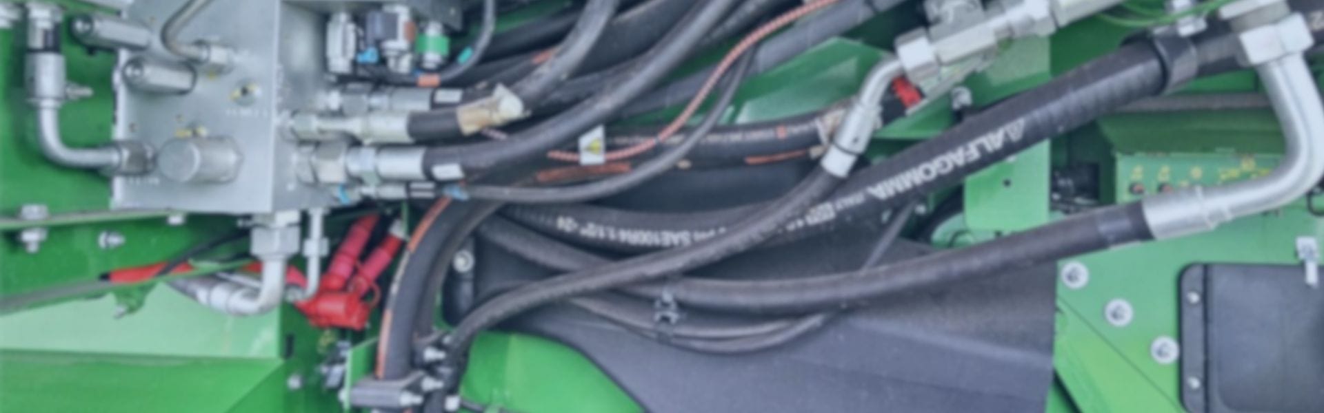
Hydraulic fluid lines serve as the circulatory system of hydraulic machinery, responsible for transmitting hydraulic fluids between components such as pumps, valves, and actuators. These lines, which include hoses, pipes, and tubes, play a crucial role in maintaining system pressure and ensuring the smooth and reliable transfer of energy. A well-designed hydraulic fluid line can optimize the performance and longevity of hydraulic systems, whereas poorly designed lines can lead to inefficiencies, pressure loss, or even system failures.

Understanding Hydraulic Fluid Lines

What Are Hydraulic Fluid Lines?

Hydraulic fluid lines are the pathways through which hydraulic fluid is transmitted within a hydraulic system, acting as the conduits for power transmission. These lines can take the form of hoses, pipes, or tubes and are designed to transport hydraulic fluids between key components such as pumps, actuators, cylinders, and valves. The primary function of hydraulic fluid lines is to ensure the efficient transfer of hydraulic fluid, which in turn generates the force needed to power hydraulic machinery.

Hydraulic fluid lines must withstand various operating conditions such as high pressure, extreme temperatures, and external mechanical stresses, making the proper design and material selection crucial for system integrity. Depending on the application and environment, these lines may be flexible or rigid, and the choice between hoses, pipes, or tubes often depends on factors like pressure rating, flexibility, and the need for easy routing.

Brake Line Union Applications

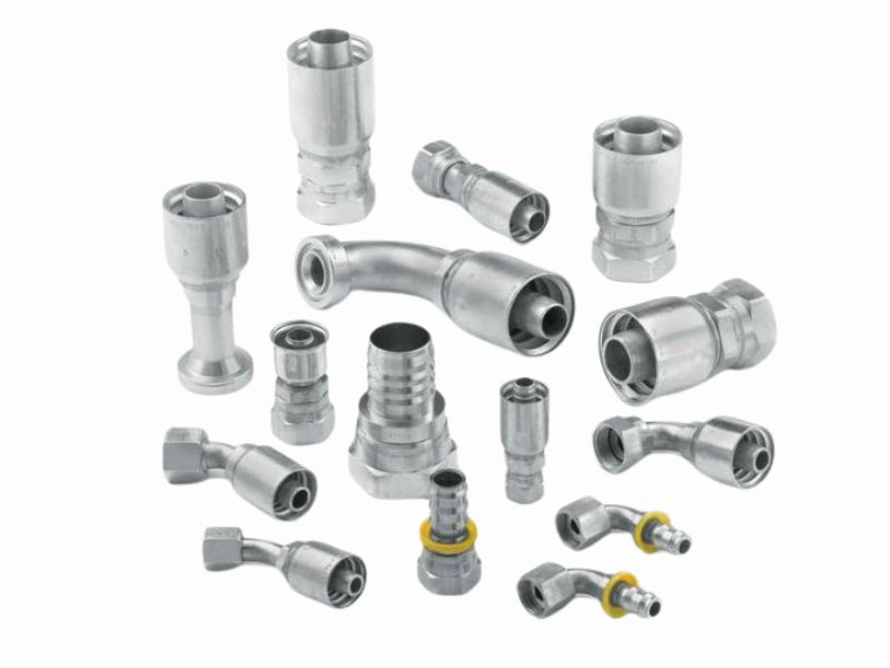
Overview of Types of Hydraulic Fluid Lines

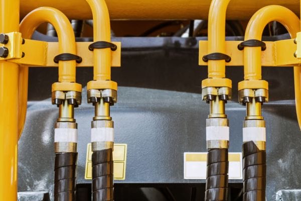
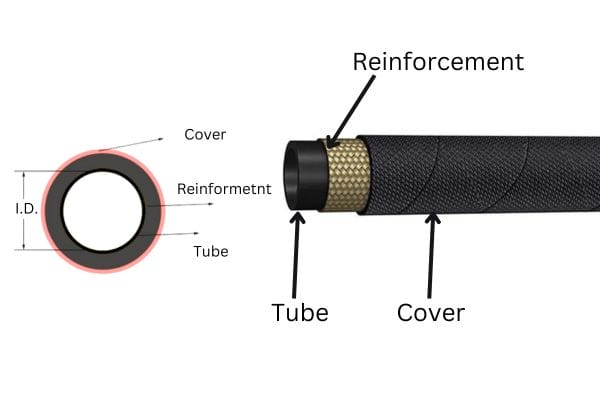
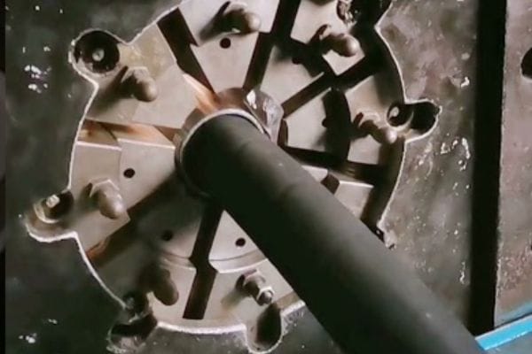
Hoses: Flexible tubes made from synthetic rubber, thermoplastic, or PTFE, reinforced with steel wire or fabric. Hydraulic hoses are ideal for systems requiring flexibility and are commonly used in mobile machinery or applications with moving parts.

Pipes: Rigid, seamless steel or stainless steel pipes that provide durable and high-pressure fluid transmission. Pipes are typically used in stationary applications where flexibility is not needed.

Tubes: Tubing is also rigid but lighter than pipes and is often used in medium- to high-pressure applications. Tubes are often bent or formed to fit specific system designs and are commonly found in industrial equipment.

Importance in Hydraulic Systems

Hydraulic fluid lines are vital to maintaining consistent pressure and fluid flow within a hydraulic system. Properly designed lines ensure that hydraulic fluid moves efficiently, with minimal loss of pressure or energy. This fluid transfer enables the system to deliver the necessary power to actuators and cylinders, allowing hydraulic machinery to perform tasks such as lifting, pressing, or rotating with precision and strength.

Key Principles of Hydraulic Line Modeling

Fluid Dynamics in Hydraulic Lines

Fluid dynamics play a critical role in determining the performance of hydraulic fluid lines. In hydraulic systems, the movement of fluid through pipes, hoses, or tubes generates flow, pressure, and resistance—all of which impact the overall efficiency of the system. Understanding fluid dynamics is essential for accurate hydraulic line modeling because it helps predict how fluids will behave under different operating conditions, such as pressure changes, temperature fluctuations, and varying load requirements.

Key factors that influence hydraulic line performance include:

Pressure: Pressure is the driving force that moves hydraulic fluid through the system. Maintaining consistent pressure is essential for the system to function properly. Fluid line modeling must account for pressure drops that can occur due to friction, improper line sizing, or turbulent flow, all of which can reduce the system’s efficiency.

Flow Rate: Flow rate refers to the volume of hydraulic fluid that moves through the line over a given period of time. Higher flow rates are required for systems with high demands for power or speed. Inaccurate modeling of flow rates can result in either too much or too little fluid reaching key components, which can affect the system’s performance and potentially cause damage.

Fluid Velocity: Fluid velocity is the speed at which the hydraulic fluid moves through the line. Higher velocities can cause increased turbulence, friction, and heat generation, which can degrade system components over time. In modeling, it is crucial to optimize velocity to balance system efficiency and component longevity.

Resistance: Resistance in hydraulic lines is caused by friction between the fluid and the walls of the pipes or hoses. The more resistance present in the lines, the more energy is required to maintain pressure, leading to inefficiencies. Factors such as the roughness of the material’s surface bends, and fittings contribute to resistance, and these need to be carefully modeled to minimize losses.

Material Selection and Its Impact

Choosing the right material for hydraulic fluid lines is another fundamental aspect of modeling. The material selected affects the line’s ability to handle pressure, withstand temperature variations, and resist wear. Different materials offer varying levels of fluid transmission efficiency, and the wrong material can compromise the performance of the entire system.

Steel: Steel pipes and tubes are common in high-pressure applications due to their strength and durability. Steel offers excellent resistance to pressure and thermal expansion, making it ideal for stationary systems. However, steel is rigid, heavy, and not suited for systems that require flexibility or where frequent movement occurs.

Rubber Hoses: Rubber hoses, often reinforced with steel wire or synthetic fibers, are commonly used in hydraulic systems where flexibility is essential. Rubber hoses can handle high pressures but are more susceptible to wear, especially in harsh environments or with exposure to high temperatures.

Thermoplastics: Lightweight and flexible, thermoplastic hoses provide good chemical resistance and are often used in low- to medium-pressure systems. They are suitable for mobile machinery and applications where weight is a concern.

The material chosen must match the system’s requirements, including pressure, temperature, and fluid type, to ensure long-term reliability and performance.

Cleaning Your Hydraulic Hose Assembly

Sizing and Compatibility

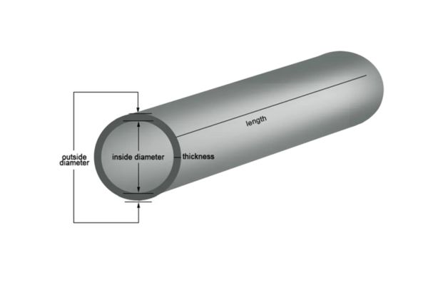
One of the most crucial aspects of hydraulic line modeling is selecting the appropriate size for the fluid lines. The inner diameter (ID) and outer diameter (OD) of the lines directly influence the flow of hydraulic fluid, the system’s ability to maintain pressure, and the overall efficiency of the system.

Inner Diameter (ID): The ID of a hydraulic line determines the amount of fluid that can flow through it. If the ID is too small, it can restrict fluid flow, leading to pressure drops and reduced system efficiency. Conversely, if the ID is too large, the system may experience lower fluid velocity, resulting in sluggish performance and potential heat buildup.

Outer Diameter (OD): The OD affects the structural integrity of the line and its ability to withstand external pressures and mechanical stresses. Proper OD selection ensures that the line is durable enough for the system’s operating environment while maintaining ease of installation.

Incorrect sizing of hydraulic fluid lines can result in issues such as:

Pressure Loss: When the ID is too small for the system’s flow rate, it causes excessive friction and resistance, leading to a significant pressure drop. This reduces the system’s power and efficiency, requiring more energy to maintain performance.

Turbulence: Improperly sized lines can cause turbulence, where the fluid does not flow smoothly through the line. This can lead to increased wear on the system’s components, reduced flow control, and inefficiencies.

Cavitation: Cavitation occurs when the pressure in the hydraulic system drops below the vapor pressure of the fluid, causing vapor bubbles to form. These bubbles can collapse violently, damaging components and reducing the system’s lifespan. Incorrect line sizing, particularly with too-small diameters, can contribute to cavitation.

Techniques for Accurate Hydraulic Line Modeling

1D and 3D Modeling Techniques

Hydraulic line modeling can be approached in both one-dimensional (1D) and three-dimensional (3D) formats, depending on the complexity of the system and the desired outcomes. Each method has its advantages and is suited for different applications.

1D Modeling: One-dimensional modeling simplifies the hydraulic system into a linear framework where parameters such as pressure, flow rate, and velocity are functions of distance along the line. This approach is highly efficient for basic systems where the primary concern is fluid flow rather than complex interactions within the system. In 1D modeling, the system is typically reduced to a series of equations that govern flow dynamics, making it faster and less resource-intensive than 3D modeling. It is useful for applications where rapid evaluations of flow and pressure changes are needed.

Applications: 1D modeling is often used for early-stage design when engineers need to assess general flow characteristics and pressure losses across a hydraulic network. It’s also useful for systems where the geometry is relatively straightforward, such as long pipeline networks, simple hose systems, or when simulating basic fluid transfers.

3D Modeling: In three-dimensional modeling, the fluid and system components are represented in full spatial detail, allowing for more precise simulations of how fluid behaves in complex geometries. 3D modeling accounts for fluid dynamics in all directions and can simulate interactions like turbulence, frictional losses, and the effects of fittings, bends, or other components.

Applications: 3D modeling is used when high accuracy is required, especially in systems with complicated geometries, such as in confined spaces, where pipes and hoses have multiple bends, or in machinery where components interact closely with the fluid lines. It is also applied when studying detailed aspects of system behavior, such as how fittings or valves affect flow, or when evaluating temperature gradients across different parts of the system.

Finite Element Analysis (FEA)

Finite Element Analysis (FEA) is a crucial tool in hydraulic line modeling that helps in understanding how fluid lines behave under stress and pressure. FEA breaks down the hydraulic system into small, finite elements, allowing for the analysis of how pressure, force, and stress are distributed throughout the fluid line.

Weak Points Identification: One of the key advantages of FEA is its ability to pinpoint weak spots in the hydraulic system. By modeling stress and strain at the granular level, FEA helps engineers identify areas where pressure is concentrated, where material failure is likely to occur, or where excessive wear may happen due to repeated stress.

Pressure Distribution: FEA is also used to analyze how pressure is distributed across the system. In hydraulic lines, pressure distribution is critical for ensuring that the system maintains its efficiency. FEA allows engineers to model how fluid pressure changes as it moves through the system and how different components (such as fittings, valves, or bends) affect that pressure.

Structural Integrity: Another essential aspect of FEA is evaluating the structural integrity of the hydraulic lines. Whether made from steel, rubber, or composite materials, hydraulic lines must withstand high pressures without deforming or breaking. FEA simulates these conditions, providing valuable insights into how well the materials will perform under real-world stresses and allowing engineers to optimize material choices and line configurations.

Thermal and Pressure Considerations in Modeling

Hydraulic systems often operate in environments where temperature and pressure vary widely, and accounting for these factors is essential in hydraulic line modeling. The temperature affects both the hydraulic fluid and the materials used in the lines, while pressure determines the efficiency and performance of the system.

Incorporating Temperature Effects: Temperature variations can change the viscosity of hydraulic fluids, which in turn affects flow rates, pressure losses, and overall system performance. Cold temperatures can make fluids more viscous, reducing flow and causing sluggish operation, while high temperatures can lead to thinning of the fluid, decreasing system efficiency. Accurate hydraulic line modeling must account for these temperature-induced changes to ensure the system performs well across different operating environments.

Thermal Expansion and Contraction: The materials used in hydraulic lines (such as steel, rubber, or composites) expand and contract with temperature changes. If these changes are not incorporated into the modeling process, thermal stresses can lead to line fatigue, cracks, or leaks. Incorporating allowances for thermal expansion and contraction ensures that the hydraulic system remains structurally sound, even when temperatures fluctuate.

Pressure Impacts: High-pressure conditions, especially in dynamic applications, can lead to pressure surges that stress hydraulic lines and components. Pressure spikes, also known as “water hammer,” can damage the system if not properly accounted for. Effective modeling techniques include pressure-dampening measures and simulations that mimic real-world operating pressures to prevent failures.

Tips for Effective Hydraulic Line Modeling

Tip 1: Understand the System’s Operating Conditions

One of the most fundamental aspects of hydraulic line modeling is an in-depth understanding of the system’s specific operating conditions.  

Modeling for Temperature and Pressure Variations: Hydraulic systems often operate in environments where temperatures fluctuate dramatically, from sub-zero conditions to extreme heat. Temperature changes directly impact the viscosity of hydraulic fluids and the behavior of materials used in fluid lines. If not accounted for, temperature variations can lead to inefficiencies, excessive wear, or even system failure. For instance, cold conditions may increase fluid viscosity, resulting in slower movement, while high temperatures can cause thinning of the fluid, reducing system efficiency. In hydraulic line modeling, it’s critical to simulate how temperature impacts fluid flow and pressure over the full range of anticipated operating conditions.

Environmental Factors: External environmental conditions—such as exposure to chemicals, UV light, moisture, or dust—also affect how hydraulic lines perform. For example, hoses and pipes exposed to outdoor environments might face accelerated wear and degradation from UV light or chemical exposure. Incorporating these environmental factors into the modeling process ensures the right materials and designs are chosen to withstand these challenges over time.

Understanding these factors early in the modeling process allows for more precise simulations and ensures the hydraulic lines meet the requirements of the operating environment.

Tip 2: Factor in Line Flexibility and Movement

Hydraulic systems often require both rigid and flexible fluid lines, depending on the application. Flexibility plays a significant role in how hydraulic lines behave under stress, movement, and vibration, and this must be accurately reflected in the model.

Flexible vs. Rigid Lines: Flexible hoses are commonly used in systems that require movement or where space constraints make rigid lines impractical. However, flexible lines can experience wear and tear from repeated bending, vibration, or high pressures. These lines need to be reinforced and placed in areas where movement will not cause excessive strain. On the other hand, rigid pipes or tubes are better suited for stationary applications and can handle higher pressures without deformation. However, they require precise routing to avoid stress points that can lead to cracks or fractures.

Design Considerations: When designing hydraulic lines, it is essential to account for potential movement and vibration within the system. Flexible hoses should be modeled with enough slack to allow for movement without being overstretched. Vibration dampeners or brackets can also be included to reduce wear. Additionally, the use of swivel joints or live swivels at connection points can help reduce stress on the lines by allowing them to move freely without twisting or bending, which is crucial in mobile or high-vibration environments.

By modeling both flexible and rigid lines appropriately, engineers can reduce wear, prevent premature failures, and ensure system longevity.

Modeling Hydraulic Fluid Lines

Tip 3: Minimize Pressure Drops

Pressure drop is a common issue in hydraulic systems, and it can severely affect system performance. Reducing pressure loss across hydraulic lines is critical to ensuring the system operates efficiently and reliably.

Reducing Friction: One of the primary causes of pressure loss in hydraulic lines is friction between the fluid and the inner surface of the line. Minimizing this friction is crucial for maintaining pressure and flow rates. Using smooth-bore hoses or tubes with low-friction materials can reduce the amount of resistance the fluid encounters, thus reducing pressure loss.

Correct Line Sizing: Line sizing plays a significant role in minimizing pressure drops. Hydraulic lines with a smaller inner diameter (ID) can restrict flow, leading to increased friction and pressure loss. Conversely, lines that are too large may reduce fluid velocity, causing inefficient system operation. The key is to model and select lines that are appropriately sized for the system’s flow rate and pressure requirements.

Smooth Bends and Routing: Hydraulic systems often require lines to be routed through tight spaces, which can lead to sharp bends. These bends cause turbulence and increase pressure drop. By using smooth, gradual bends instead of sharp angles, engineers can maintain a more consistent flow. Routing lines in a way that minimizes bends, loops, and intersections is essential for reducing resistance and ensuring smooth fluid movement.

Tip 4: Account for Fluid Properties

Fluid properties—such as viscosity and density—are integral to hydraulic line modeling. These characteristics influence how fluids move through lines, how pressure is maintained, and how the system performs under different operating conditions.

Viscosity: Fluid viscosity is a measure of its resistance to flow. Higher viscosity fluids (thicker fluids) will flow more slowly and encounter more resistance as they move through the system, which can lead to pressure loss and reduced efficiency. Conversely, low-viscosity fluids may flow too quickly, creating turbulence or cavitation issues. When modeling hydraulic lines, it’s important to consider how fluid viscosity changes with temperature. Cold environments increase viscosity, while hot environments decrease it. The model should account for these variations to maintain optimal system performance across different temperatures.

Density: Fluid density impacts the amount of force required to move the fluid through the system. Denser fluids require more energy to move, which can increase system pressure and stress on components. When modeling hydraulic lines, engineers should adjust line sizing and pressure settings based on the specific fluid’s density to ensure smooth operation.

By considering the properties of the hydraulic fluid, engineers can optimize line design, avoid common flow issues, and ensure the system operates efficiently across various conditions.

Common Challenges in Hydraulic Line Modeling and How to Overcome Them

Handling Complex Geometries

One of the biggest challenges in hydraulic line modeling is dealing with complex geometries, especially in systems with confined spaces, multiple bends, or irregular layouts. These complex configurations can significantly affect fluid flow, pressure distribution, and overall system efficiency.

Challenges in Complex Spaces: In confined or irregular spaces, hydraulic lines often need to navigate sharp corners, bends, and tight clearances, which can introduce issues like turbulence, pressure drops, and stress on the lines. Fittings, joints, and connections in these areas can further complicate the flow, as they create resistance and potential leak points.

Simplifying Geometry Without Compromising Accuracy: To overcome these challenges, hydraulic line modeling requires a balance between simplicity and accuracy. One approach is to use smooth, gradual bends rather than sharp angles, which helps maintain fluid flow and reduces turbulence. Additionally, designers can create simplified models that focus on key flow areas, such as bends and critical fittings, while minimizing the complexity of less crucial sections. Advanced software tools also allow for detailed 3D models that simulate fluid flow around bends and through tight spaces, providing insights into potential problem areas.

Routing Considerations: Careful routing of hydraulic lines can alleviate many geometric challenges. Routing lines in parallel, reducing the number of fittings and sharp angles, and ensuring sufficient spacing between components all contribute to smoother fluid flow and reduced pressure losses.

Pressure Transients and Water Hammer

Pressure transients, also known as water hammers, occur when there is a sudden change in fluid velocity, causing shockwaves to propagate through the hydraulic system. These surges can cause significant damage to hydraulic lines, fittings, and system components, making it a crucial factor to consider in hydraulic line modeling.

Overview of Water Hammer Effects: Water hammer occurs when there is a rapid change in flow, such as when valves open or close suddenly, causing a pressure spike. This spike can travel through the hydraulic lines, leading to stresses on the system that can result in bursts, leaks, or component failure. In hydraulic systems, water hammer can also lead to cavitation, where vapor bubbles form and collapse, damaging the inner surfaces of the lines.

Mitigating Pressure Transients: Several techniques can be employed to mitigate the impact of water hammer in hydraulic line models:

Gradual Valve Operation: By designing models that account for gradual valve opening and closing times, fluid flow changes can be more controlled, reducing pressure spikes.

Using Surge Tanks or Accumulators: These devices can absorb pressure surges, reducing the impact of the water hammer on the system. Including them in hydraulic line models helps smooth out pressure transients.

Pressure Relief Valves: Placing pressure relief valves in the system can allow for controlled release of excess pressure, preventing damage from sudden surges.

Fluid Dampening: Modeling fluid dampeners can help absorb energy from pressure spikes, reducing the chance of water hammer effects.

By incorporating these techniques, models can better simulate real-world hydraulic systems and ensure that pressure transients are effectively mitigated.

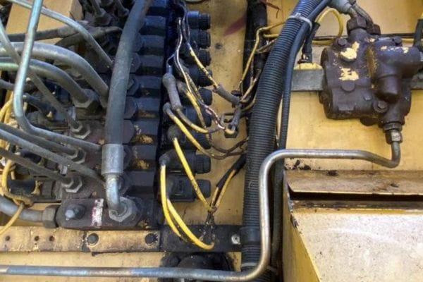
Wear and Aging of Materials

Hydraulic lines and components are subject to wear and aging over time, which can impact system performance and lead to potential failures. Modeling the effects of wear and material degradation is crucial to predicting the lifespan of a hydraulic system and planning maintenance strategies.

Modeling Material Wear and Degradation: Over time, hydraulic lines experience wear due to friction, pressure cycling, temperature fluctuations, and environmental factors such as exposure to chemicals or UV radiation. This wear can cause thinning of the walls of hoses, pipes, or tubes, leading to leaks, bursts, or failure of fittings. In high-pressure systems, repeated stress can also cause micro-cracks to form, gradually weakening the material.

Incorporating Life Cycles into Modeling: To effectively account for wear and aging in hydraulic line modeling, engineers must consider the expected lifespan of materials under different operating conditions. This includes:

Pressure Cycling: Modeling how repeated pressure cycles cause material fatigue over time.

Temperature Stress: Understanding how temperature fluctuations contribute to material degradation, such as cracking in colder environments or softening in extreme heat.

Corrosion and Abrasion: In environments where hydraulic lines are exposed to harsh chemicals or abrasive particles, corrosion or abrasion can shorten the lifespan of the lines. Modeling should account for material degradation rates in these conditions.

Predictive Maintenance: By incorporating wear and aging data into hydraulic line models, engineers can predict when maintenance or replacement of components will be required. This proactive approach helps prevent unexpected failures and extends the lifespan of the system.

Conclusion

Accurate hydraulic line modeling plays a vital role in enhancing system performance, reliability, and safety. By predicting how fluid lines will behave under real-world conditions, engineers can prevent costly issues like pressure loss, water hammer, or premature material failure. With proper planning and modeling, hydraulic systems can operate more efficiently, reduce downtime, and extend the life of their components.


FAQ

What is hydraulic fluid line modeling?

Hydraulic fluid line modeling is the process of simulating the behavior of hydraulic fluid within hoses, pipes, and tubes to predict system performance and optimize design.

Why is accurate modeling important in hydraulic systems?

Accurate modeling helps prevent issues such as pressure loss, cavitation, and material failure, leading to improved efficiency, reliability, and longevity of hydraulic systems.

What are the key factors to consider in hydraulic line modeling?

Important factors include fluid dynamics, pressure, flow rate, material selection, line sizing, and thermal expansion.

What tools are used for hydraulic line modeling?

Common tools include SolidWorks, ANSYS, and MATLAB, which allow for simulations such as Finite Element Analysis (FEA) and Computational Fluid Dynamics (CFD).

How does pressure drop affect hydraulic systems?

Pressure drops can reduce the system’s efficiency, causing components to work harder and leading to overheating or system failure.

What is the role of fluid properties in modeling?

Fluid properties like viscosity and density affect flow behavior, pressure distribution, and system performance, making them crucial to consider in hydraulic line modeling.

Poppet-Type Quick Couplings banner

Poppet-Type Quick Couplings: What You Need to Know

Hydraulic couplings are devices that connect hoses, pipes, or tubes in a hydraulic system, allowing for the seamless transfer of pressurized fluid. Among the various types of couplings available, poppet-type hydraulic couplings stand out due to their unique valve design, which offers superior sealing and high-pressure handling capabilities. These couplings are equipped with a poppet valve that seals automatically when disconnected, preventing fluid loss and contamination, making them an essential choice for high-pressure and rugged applications.

What Are Poppet-Type Hydraulic Couplings?

Basic Definition

Poppet-type hydraulic couplings are a specific class of quick-disconnect couplings used in hydraulic systems to connect or disconnect fluid lines without causing significant fluid loss or introducing contaminants into the system. The distinguishing feature of this coupling is the poppet valve, a spring-loaded valve that ensures fluid control when connecting or disconnecting. Poppet-type couplings are designed to handle high-pressure systems and are often used in demanding applications where performance and safety are critical.

These couplings are built to seal effectively and prevent leakage, even when subjected to high levels of pressure. They are highly favored in industries like construction, agriculture, and defense due to their durability and reliability in harsh environments. The robust design of the poppet valve allows the coupling to endure rigorous conditions while maintaining performance, making it ideal for both mobile and industrial hydraulic systems.

How They Work

The core mechanism behind poppet-type hydraulic couplings lies in the poppet valve, which acts as the sealing element within the coupling. This valve is typically spring-loaded and positioned to remain closed when the coupling is disconnected. Here’s a breakdown of the process:

Connection:

When the male and female halves of the coupling are connected, the poppet valves in both parts are pushed open, allowing fluid to flow through the hydraulic line. The alignment of the internal components ensures that the valves open only when a secure connection is made, preventing accidental spills or pressure loss.

Disconnection:

When the coupling is disconnected, the poppet valve in each half immediately closes, stopping the flow of fluid. This automatic sealing action prevents hydraulic fluid from leaking out and keeps contaminants from entering the system.

Sealing Mechanism:

The valve’s spring ensures that it returns to the closed position as soon as the connection is broken, maintaining the integrity of the hydraulic line. The poppet valve’s precision design ensures a tight seal, even under high-pressure conditions.

This self-sealing design makes poppet-type couplings particularly useful in systems where the fluid is under high pressure or where the cleanliness of the fluid is critical to the system’s operation. The prevention of fluid loss not only conserves the hydraulic fluid but also minimizes the environmental impact, which is a significant concern in many industries.

brass ISO 7241 1 Series B Hydraulic Couplings

Comparison to Other Coupling Types

Poppet-type hydraulic couplings differ from other common hydraulic couplings in several key ways. One notable comparison is with ball-type couplings, another popular type of quick-disconnect hydraulic coupling.

Poppet-Type vs. Ball-Type Couplings:

Sealing Mechanism:

Poppet-type couplings use a spring-loaded valve that closes automatically upon disconnection, ensuring a tight seal. Ball-type couplings, on the other hand, use a series of small balls to hold the two coupling halves together. When disconnected, ball-type couplings often allow more fluid leakage compared to poppet-type couplings, which have superior sealing.

Pressure Rating:

Poppet-type couplings are generally better suited for high-pressure systems because their valve design can withstand greater forces. In contrast, ball-type couplings are more commonly used in lower to moderate pressure applications.

Fluid Flow:

Poppet-type couplings can restrict fluid flow more than ball-type couplings due to the internal poppet valve, which slightly reduces the diameter of the flow path. Ball-type couplings, by comparison, offer a more open flow, which can be advantageous in systems where maximum flow is required.

Poppet-Type vs. Flat-Face Couplings:

Flat-face couplings are known for their zero-leak design, making them ideal for applications where fluid cleanliness and preventing spillage are the top priorities. While poppet-type couplings offer excellent sealing, they may not achieve the same zero-leak performance as flat-face couplings. However, poppet-type couplings excel in higher-pressure environments compared to flat-face designs.

Flat-face couplings tend to have a simpler design, which makes them easier to clean and maintain in environments where dirt and debris are concerns, while poppet-type couplings’ more intricate valve design offers better control over fluid disconnection and reconnection.

Key Features of Poppet-Type Hydraulic Couplings  

Design and Structure

Poppet-type hydraulic couplings are engineered with a unique internal structure that contributes significantly to their performance, especially in high-pressure systems. The core element of these couplings is the poppet valve, a spring-loaded mechanism that plays a crucial role in sealing and fluid control. The poppet valve opens only when the male and female halves of the coupling are fully engaged, ensuring that fluid transfer occurs without any leaks. When disconnected, the valve instantly closes, preventing fluid loss and contamination.

The coupling typically consists of two main components: the male (plug) and the female (socket) halves. Each half contains a poppet valve, and upon connection, the valves depress and open to allow hydraulic fluid to flow. The valves are spring-loaded, meaning that when the coupling is disconnected, the poppet automatically returns to a closed position, effectively sealing both ends.

This design not only ensures excellent sealing but also provides protection against accidental disconnections, which could otherwise result in dangerous fluid leaks. The structure also includes robust seals, such as O-rings, which help maintain pressure and prevent leaks at the points where the coupling connects.

Pressure Handling

One of the standout features of poppet-type hydraulic couplings is their ability to handle high-pressure environments. These couplings are designed to perform in systems where pressures can exceed 5000 psi (pounds per square inch) or more, making them ideal for industrial, mobile, and other heavy-duty applications.

In high-pressure systems, the integrity of the connection between hydraulic lines is critical, and poppet valves ensure that the hydraulic fluid remains contained and under control. Their ability to manage such pressure without compromising on safety or performance is one of the main reasons they are favored in industries where reliability is paramount.

Durability and Resistance

Poppet-type hydraulic couplings are built with durability in mind. The materials used in their construction often include hardened steel, brass, stainless steel, or chrome plating, which gives them excellent resistance to wear, corrosion, and extreme temperatures. These materials ensure that the coupling can endure the harsh conditions often encountered in industries like construction, oil & gas, and agriculture.

Additionally, the poppet valve design contributes to reduced wear on the coupling, as the valve opens only when connected, minimizing exposure to external elements like dirt, moisture, or chemicals. This enhances the longevity of the coupling, reducing the need for frequent replacements or maintenance.

Sealing Efficiency

The sealing efficiency of poppet-type hydraulic couplings is one of their most significant advantages. When the coupling is disconnected, the poppet valve immediately seals off the fluid flow, preventing leaks. This sealing efficiency is particularly important in systems that require leak-tight performance to maintain pressure and protect sensitive components.

The sealing is also crucial in applications where environmental cleanliness is a priority, such as in the aerospace or food processing industries, where fluid contamination can have severe consequences.

Benefits of Using Poppet-Type Hydraulic Couplings

Improved Safety:

Poppet-type couplings are designed to prevent fluid leakage during disconnection, significantly enhancing system safety. In hydraulic systems, leaks can lead to hazardous working conditions, environmental damage, and even system failure. The automatic sealing of the poppet valve ensures that no fluid escapes during disconnection, which is particularly critical in high-pressure systems.

Ease of Use:

These couplings are designed to allow for quick and easy connections and disconnections without the need for excessive force. This ease of use improves operational efficiency, especially in applications where couplings need to be frequently connected or disconnected, such as in mobile hydraulics.

Longer Lifespan:

Thanks to their robust construction and effective sealing mechanisms, poppet-type couplings tend to have a longer lifespan than other coupling types. The durability of the materials used, combined with the poppet valve’s protective design, reduces wear and tear, extending the service life of the coupling and minimizing maintenance needs.

Leak Prevention:

Poppet-type couplings excel in leak prevention. The poppet valve, combined with high-quality O-rings and seals, ensures a leak-tight connection even under high pressure. This minimizes fluid loss, which can help improve system efficiency and reduce operational costs.

Performance in Harsh Environments:

These couplings are built to withstand rugged environments. Whether it’s extreme temperatures, corrosive fluids, or heavy mechanical stresses, poppet-type couplings are up to the task. This makes them ideal for industries such as marine, oil & gas, construction, and agriculture, where equipment is often exposed to challenging conditions.

Applications of Poppet-Type Hydraulic Couplings

Industrial Machinery:

Poppet-type couplings are widely used in industrial machinery, particularly in systems that require frequent connection and disconnection of hydraulic lines. Their high-pressure capability and leak-proof performance make them ideal for manufacturing equipment and machinery.

Agriculture:

In agricultural applications, such as tractors and harvesters, poppet-type couplings provide a reliable connection for hydraulic systems that operate in dusty, dirty, and abrasive environments. Their durability and leak prevention are essential for maintaining efficient operation in tough field conditions.

Aerospace and Defense:

High-performance aircraft and military vehicles rely on hydraulic systems for critical functions, and poppet-type couplings are often chosen for their ability to handle extreme pressure and ensure a secure, leak-free connection. These systems need couplings that can perform reliably in high-pressure, high-stakes environments.

Marine and Oil & Gas:

In the marine and oil & gas sectors, poppet-type couplings are used in hydraulic systems where high pressure, corrosive environments, and extreme temperatures are the norm. Their corrosion-resistant materials and robust sealing make them an excellent choice for offshore platforms and subsea equipment.

Installation and Maintenance Best Practices  

Proper Installation

Ensuring the proper installation of poppet-type hydraulic couplings is essential to prevent damage and ensure optimal performance. Here are the key steps for installing these couplings:

Inspect the Coupling Components:

Before installation, inspect both the male and female halves of the coupling for any signs of damage, dirt, or debris. Any contaminants or physical damage could impair the coupling’s sealing ability or lead to improper connections.

Clean the Connection Points:

Make sure the connection points (both male and female) are clean and free from any particles or residues that could affect the sealing performance. Dirt and debris can cause premature wear and tear and compromise the coupling’s ability to handle pressure.

Align the Coupling Properly:

Proper alignment is crucial to ensure a tight, leak-free connection. Misalignment can cause damage to the poppet valve, O-rings, or other internal components, leading to leaks or inefficient fluid flow.

Engage Fully:

When connecting the two halves, ensure that they are fully engaged and locked. Most poppet-type couplings have a locking mechanism or audible click to confirm that the connection is secure.

Avoid Over-Tightening:

Over-tightening the couplings can cause unnecessary stress on the threads and internal components, leading to damage. Use the appropriate amount of torque recommended by the manufacturer to ensure a secure but non-damaging connection.

Pressure Testing:

After installation, it is advisable to perform a pressure test to ensure that the coupling is securely in place and able to handle the system’s operating pressure without leaking.

Maintenance Tips

Regular maintenance of poppet-type hydraulic couplings is essential to prolong their lifespan and prevent costly downtime. Here are some important maintenance practices to follow:

Routine Inspection:

Regularly inspect the couplings for signs of wear, corrosion, or physical damage. Pay close attention to the sealing areas, including the O-rings and the poppet valve. Even minor damage to these parts can lead to leaks or system inefficiencies.

Cleaning:

Clean the coupling regularly, especially in dirty or abrasive environments. Use a clean, lint-free cloth to wipe down the coupling surfaces and remove any dust, dirt, or grime. Avoid using aggressive chemicals that may degrade the seals or metal components.

Lubrication:

Apply manufacturer-recommended lubrication to the threads and seals periodically to reduce friction during connection and disconnection. This will help maintain the integrity of the seals and prevent premature wear.

Part Replacement:

Over time, components such as O-rings and seals may wear out and need replacement. Regularly check these parts and replace them as needed to maintain sealing efficiency and pressure integrity.

Poppet-Type Quick Couplings

Common Issues and Troubleshooting

Even with proper installation and maintenance, poppet-type hydraulic couplings can experience issues over time. Here are some common problems and how to troubleshoot them:

Leaks:

Cause: Leaks often occur due to worn-out or damaged seals, misalignment, or contaminants preventing the proper closure of the poppet valve.

Solution: Inspect the seals and O-rings for wear or damage and replace them if necessary. Ensure that the coupling halves are properly aligned and securely engaged. Clean the connection points to remove any dirt or debris that may interfere with the seal.

Difficulty Connecting or Disconnecting:

Cause: If you are having trouble connecting or disconnecting the coupling, it could be due to pressure build-up in the system, misalignment, or worn components.

Solution: Relieve any built-up pressure in the hydraulic line before attempting to disconnect the coupling. Check for proper alignment and ensure that the coupling halves are not worn or damaged. Lubricating the coupling may also ease the connection process.

Reduced Performance:

Cause: Reduced system performance can be a sign of restricted fluid flow caused by blockages or damage to the internal components of the coupling.

Solution: Disassemble the coupling and inspect the poppet valve and other internal parts for any obstructions, dirt, or damage. Clean or replace any damaged components to restore full fluid flow.

Corrosion or Rust:

Cause: Exposure to moisture or corrosive environments can cause the metal components of the coupling to rust or corrode, leading to weakened performance.

Solution: Clean the coupling thoroughly and apply anti-corrosion lubricants. If the corrosion is severe, consider replacing the coupling with one made from corrosion-resistant materials such as stainless steel.

Premature Wear:

Cause: Premature wear is often caused by contaminants, over-tightening, or improper maintenance.

Solution: Follow a regular maintenance schedule, clean the couplings frequently, and ensure proper torque during installation. Replace any worn parts as needed.

Poppet-Type vs Other Coupling Types  

Ball-Type Couplings

Ball-type hydraulic couplings, also known as ball-lock couplings, differ from poppet-type couplings in both design and operation. Instead of the spring-loaded poppet valve used in poppet-type couplings, ball-type couplings rely on a series of small steel balls that lock the two halves of the coupling together when connected. When disconnected, a valve closes the fluid path to prevent leakage, though not always as efficiently as a poppet valve.

Design and Operation:

Ball-type couplings have a relatively simple design, making them easier to manufacture and maintain.

They are typically used in lower to moderate-pressure systems where the quick connection and disconnection of hydraulic lines are essential.

Fluid leakage is more common compared to poppet-type couplings, especially under high pressure, due to the less efficient sealing mechanism.

Applications:

Ball-type couplings are often found in low to medium-pressure applications, such as light-duty industrial machinery, automotive systems, and mobile hydraulics.

They are well-suited for systems where quick disconnection is required without the need for extremely tight sealing, as seen in some agricultural equipment or light construction tools.

ISO16028 Flat Face Hydraulic Coupler

Flat-Face Couplings

Flat-face couplings, as the name suggests, feature flat mating surfaces that form a seal when connected. This design minimizes fluid loss during disconnection, making them ideal for environments where cleanliness and the prevention of contamination are paramount.

Design and Operation:

Unlike poppet and ball-type couplings, flat-face couplings have no protruding valve elements, resulting in a completely flat surface when disconnected. This design prevents fluid from collecting on the face, which can reduce leakage and contamination.

They are known for their zero-leak performance during both connection and disconnection, making them the preferred choice in industries where fluid loss must be minimized.

Applications:

Flat-face couplings are commonly used in industries such as construction, agriculture, and material handling, where cleanliness is crucial, and the prevention of contamination is a priority.

These couplings are often used in hydraulic systems handling environmentally sensitive fluids or where dirt, dust, and other contaminants must be kept out of the system.

Which Is Best for Your Needs?

The choice between poppet-type, ball-type, and flat-face couplings depends largely on your system’s operating pressure, the type of hydraulic fluid used, and the working environment. Here’s a brief decision-making guide:

Poppet-type couplings are best suited for high-pressure systems that require a tight, reliable seal to prevent leaks. They are ideal for rugged applications, such as industrial machinery, aerospace, and defense systems, where leakage prevention and durability are key.

Ball-type couplings are appropriate for low to medium-pressure systems where quick connections are required, and small fluid losses are acceptable. They are most useful in mobile applications or light-duty industrial settings, such as agriculture or automotive.

Flat-Face Couplings excel in applications where cleanliness is crucial, and zero-leak performance is necessary. These are typically used in environments like construction or material handling, where preventing contamination of the fluid is a priority.

Conclusion

If you’re considering poppet-type hydraulic couplings for your system, it’s essential to consult with experts to ensure you’re choosing the right type based on your specific pressure requirements, fluid type, and operating environment. Don’t compromise on the safety and efficiency of your hydraulic system—make informed decisions and opt for reliable, high-performance couplings that meet your needs.


FAQ

What is a poppet-type hydraulic coupling?

A poppet-type hydraulic coupling is a quick-connect coupling designed to prevent fluid loss and contamination using a spring-loaded poppet valve that seals automatically when disconnected.

What are the benefits of poppet-type hydraulic couplings?

Poppet-type couplings provide excellent sealing, handle high pressure, prevent leaks, and are durable in rugged environments.

Where are poppet-type hydraulic couplings typically used?

These couplings are commonly used in industries like construction, agriculture, aerospace, and marine applications where high-pressure performance is required.

How do poppet-type hydraulic couplings prevent leaks?

The poppet valve automatically closes when the coupling is disconnected, ensuring minimal fluid loss and preventing contamination.

How often should poppet-type hydraulic couplings be maintained?

Regular inspections, cleaning, and seal replacement should be performed, especially in harsh working conditions, to maintain optimal performance.

Can poppet-type hydraulic couplings handle extreme temperatures?

Yes, they are made from materials like stainless steel and brass, which are resistant to extreme temperatures, wear, and corrosion.

Poppet vs Ball-Type Couplings banner Topa

Poppet vs Ball-Type Couplings: Key Differences

Hydraulic couplings are connectors that allow fluid to flow between hoses or pipes while preventing leaks and maintaining system pressure. The right coupling ensures seamless operation, safety, and longevity of the system. There are several types of hydraulic couplings available, but two of the most commonly used are poppet-type and ball-type couplings. Each of these coupling types has its own unique design, operation mechanism, and advantages, which make them suitable for different applications.

What Are Poppet-Type Hydraulic Couplings?

Basic Definition

Poppet-type hydraulic couplings are a class of quick-connect couplings designed to facilitate the easy connection and disconnection of hydraulic fluid lines without significant fluid loss. These couplings feature a poppet valve that automatically seals the coupling when it is disconnected, preventing fluid leakage and contamination. The unique design of the poppet valve allows for precise control of fluid flow, making these couplings suitable for high-pressure applications where maintaining system integrity is critical.

How They Work

Poppet-type couplings operate through a spring-loaded poppet valve that opens or closes depending on the coupling’s connection status. When the male and female halves of the coupling are joined, the poppet valves in both halves are pushed open, allowing hydraulic fluid to flow freely between the lines. Upon disconnection, the valves snap shut, creating a seal that stops fluid from escaping.

The spring-loaded mechanism ensures that the valve closes as soon as the coupling is disengaged, thus preventing spills and ensuring that contaminants, such as dirt or moisture, do not enter the system. This self-sealing function is particularly valuable in maintaining the cleanliness and efficiency of hydraulic systems.

ISO 7241 B Series quick coupling supplier

Design and Structure

The internal structure of a poppet-type coupling is designed to ensure efficient sealing and durability. It consists of two main components:

Male Half (Plug): This part typically houses the spring-loaded poppet valve.

Female Half (Socket): This contains a matching poppet valve and a sealing mechanism.

When connected, both poppet valves are depressed, creating a pathway for fluid to flow. When disconnected, the valves snap back into place, sealing off both the male and female halves. The poppet valve is the key component here—it consists of a small valve body that seals against a seat, held in place by a spring. This simple yet effective design ensures that no hydraulic fluid escapes when the coupling is disconnected.

In addition to the valve, O-rings and seals are often used to provide extra protection against leakage. The materials used for these components—such as hardened steel, stainless steel, or brass—are chosen for their resistance to wear, corrosion, and high pressure.

Applications

Poppet-type hydraulic couplings are used across a variety of industries, particularly in applications that demand high-pressure performance and leak prevention. Some common applications include:

Agriculture: Poppet-type couplings are commonly used in tractors, harvesters, and other hydraulic farming equipment where dirt, debris, and harsh environmental conditions are prevalent.

Construction: In heavy machinery like excavators, loaders, and cranes, poppet couplings handle the high pressures required to move hydraulic fluid effectively without leaking.

Defense and Aerospace: Military vehicles and aircraft rely on hydraulic systems for critical operations. Poppet-type couplings provide the reliability and robustness needed in high-stakes environments.

Additionally, poppet-type couplings are frequently found in industrial machinery, marine systems, and oil & gas applications, where they withstand extreme pressures and harsh working conditions.

Benefits

Poppet-type hydraulic couplings offer several key advantages that make them an ideal choice for high-pressure systems:

High-Pressure Handling: These couplings are built to withstand pressures over 5000 psi or more, making them suitable for use in industries where fluid systems operate under extreme conditions. Their robust design ensures that they maintain their integrity even in the most demanding environments.

Leak Prevention: The poppet valve design ensures that fluid loss is minimized, even during disconnection. This feature is particularly important in hydraulic systems where maintaining fluid integrity is critical for performance and safety. The self-sealing action of the valve prevents leaks, reducing the risk of system failure or environmental hazards.

Durability: Poppet-type couplings are designed for longevity. The materials used, such as stainless steel or brass, provide excellent resistance to corrosion and wear, ensuring that the coupling remains effective even in harsh environments. This makes them well-suited for outdoor or rugged applications like farming and construction.

Contamination Protection: The sealing mechanism of poppet-type couplings helps to prevent the ingress of contaminants such as dust, dirt, or moisture. This is especially beneficial in industries like agriculture, where exposure to debris is common. By keeping contaminants out, these couplings help maintain system efficiency and reduce the need for frequent maintenance.

Ease of Use: Poppet-type couplings allow for quick and easy connection and disconnection, which is essential in applications that require frequent switching of hydraulic lines. The spring-loaded mechanism ensures that users can connect and disconnect the couplings without needing excessive force, improving operational efficiency.

What Are Ball-Type Hydraulic Couplings?

Basic Definition

Ball-type hydraulic couplings, also known as ball-lock couplings, are a type of quick-connect coupling used to join or disconnect hydraulic lines quickly and efficiently. These couplings utilize a series of spring-loaded metal balls to create a secure connection between the male and female halves. The ball-type mechanism ensures a tight fit while still allowing for relatively easy connection and disconnection. Unlike poppet-type couplings, which rely on a poppet valve for sealing, ball-type couplings use the ball-locking system to hold the connection in place, making them particularly useful in moderate-pressure hydraulic systems where frequent connection changes are required.

How They Operate

The operation of ball-type hydraulic couplings is simple yet effective. The male and female halves of the coupling come together and are locked in place by metal balls housed within the coupling body. These balls are pushed into grooves on the male half of the coupling by a spring mechanism, ensuring that the connection stays secure under pressure. When the coupling needs to be disconnected, sliding back a sleeve on the female half of the coupling releases the balls, allowing the male half to disengage.

The system is designed to allow for quick, one-handed connection and disconnection, making ball-type couplings highly efficient in applications where ease of use is essential. Unlike poppet-type couplings, ball-type couplings may not always provide the same level of leak prevention, especially under high-pressure conditions. However, they are well-suited for systems where low to moderate pressures are the norm.

Design and Structure

Ball-type hydraulic couplings consist of two main parts:

Male Half (Plug): The male part of the coupling features a series of grooves or indents where the balls from the female half lock into place.

Female Half (Socket): The female half contains the ball-lock mechanism and a spring-loaded sleeve that controls the movement of the balls into and out of the locking position.

When the two halves are pushed together, the balls in the female half retract, allowing the male plug to enter. Once fully engaged, the spring forces the balls into the grooves of the male half, securing the connection. To disconnect, the operator pulls back the sleeve on the female side, which releases the balls and allows the male half to be withdrawn.

The use of metal balls for locking creates a simple yet effective mechanism for keeping the coupling secure under pressure. The design is compact, making ball-type couplings lightweight and easy to handle.

ISO 5675 Agricultural Couplings Ball Type

Applications

Ball-type hydraulic couplings are typically found in low to moderate-pressure systems where frequent connections and disconnections are necessary. Their ease of use and efficient operation make them ideal for a variety of applications:

Automotive Systems: Ball-type couplings are widely used in automotive hydraulic systems, such as brake lines, transmission systems, and fluid transfer systems. Their quick-connect design allows for easy maintenance and repairs.

Light Industrial Use: In light industrial applications, such as hydraulic tools or machinery that don’t require extremely high-pressure performance, ball-type couplings provide a reliable and efficient way to connect hydraulic lines.

Agriculture: Farming equipment, such as hydraulic sprayers and tractors, often utilize ball-type couplings because they allow for easy and quick attachment or detachment of different tools and implements, improving overall operational efficiency.

Mobile Equipment: Ball-type couplings are commonly used in mobile hydraulic systems, where ease of connection and moderate pressure handling are important factors. This includes applications like hydraulic lifts, forklifts, and smaller construction machinery.

Benefits

Ball-type couplings provide several key advantages, particularly in applications where ease of use and moderate-pressure handling are priorities:

Ease of Connection: One of the most notable benefits of ball-type couplings is their quick-connect and disconnect design. The spring-loaded sleeve mechanism allows for fast, one-handed operation, which is especially useful in applications where the operator may need to make frequent changes to hydraulic lines. This reduces downtime and increases efficiency in tasks that require multiple connections and disconnections.

Moderate-Pressure Handling: While ball-type couplings may not perform as well as poppet-type couplings in extremely high-pressure environments, they are well-suited for moderate-pressure systems. Their simple design allows them to handle everyday hydraulic tasks without the need for more complex sealing mechanisms.

Key Differences Between Poppet and Ball-Type Couplings  

When selecting hydraulic couplings for your system, understanding the differences between poppet-type and ball-type couplings is essential. Both serve similar functions in allowing fluid transfer, but their design, performance, and application suitability vary significantly.

Sealing Mechanism

The primary distinction between poppet and ball-type hydraulic couplings lies in their sealing mechanisms.

Poppet-Type Couplings: Poppet-type couplings use a spring-loaded poppet valve that seals automatically when disconnected. The poppet valve design is specifically aimed at minimizing fluid leakage when the coupling is disengaged. This feature makes poppet-type couplings highly effective in preventing fluid loss and contamination, making them ideal for systems where fluid cleanliness and leak prevention are critical. Additionally, the poppet valve provides a more robust seal, which is especially important in high-pressure systems.

Ball-Type Couplings: In contrast, ball-type couplings rely on a ball-lock mechanism to secure the connection. While this design is effective for maintaining the connection under moderate pressure, the sealing capabilities are not as strong as those of poppet-type couplings. Ball-type couplings tend to allow more fluid leakage during disconnection, which can be acceptable in lower-pressure applications but may pose problems in systems requiring tight sealing. The ball-type design focuses more on fast and easy connection rather than maximizing sealing efficiency.

Key Takeaway: If preventing fluid loss and maintaining a tight seal is a priority, poppet-type couplings are the superior choice, particularly in high-pressure environments. Ball-type couplings, while easier to use, do not offer the same level of sealing performance.

Pressure Rating

Pressure-handling capacity is another significant difference between poppet and ball-type couplings.

Poppet-Type Couplings: Poppet couplings are designed to handle high-pressure systems. Their robust construction and effective sealing make them capable of withstanding pressures that can exceed 5000 psi (pounds per square inch). This makes them ideal for heavy-duty applications in industries like construction, aerospace, and defense, where hydraulic systems often operate under extreme conditions.

Ball-Type Couplings: Ball-type couplings, on the other hand, are typically used in low to moderate-pressure systems, with pressure ratings ranging from 1000 to 3000 psi. While they are capable of handling everyday hydraulic applications, they are less suited for the extreme pressures that poppet-type couplings can endure. For applications that don’t involve high-pressure fluid flow, ball-type couplings are generally sufficient, especially where frequent disconnection is required.

Key Takeaway: For high-pressure systems, poppet-type couplings are the best choice, offering superior performance under pressure. Ball-type couplings are more appropriate for moderate-pressure systems, where pressure is less of a concern.

quick Coupling machine drawing

Durability and Wear

The durability of hydraulic couplings depends largely on the materials used and the design’s ability to resist wear and corrosion over time.

Poppet-Type Couplings: Poppet-type couplings are often constructed using high-strength materials like hardened steel, stainless steel, or brass. These materials are selected for their ability to withstand harsh environmental conditions and resist corrosion, making poppet couplings particularly suitable for rugged, outdoor environments such as construction sites or agricultural fields. The robust internal design, with well-protected poppet valves, also minimizes wear on moving parts.

Ball-Type Couplings: Ball-type couplings are typically made from similar materials, but their simpler design may result in slightly faster wear compared to poppet-type couplings in high-stress environments. The metal balls and locking grooves can wear out over time, especially in systems with frequent connections and disconnections. While ball-type couplings are still highly durable, they may not offer the same long-term performance in extreme conditions as poppet couplings.

Key Takeaway: Poppet-type couplings generally offer better durability and are more resistant to wear, making them ideal for long-term use in demanding environments. Ball-type couplings are durable but may require more frequent maintenance or replacement in high-wear situations.

Ease of Connection and Disconnection

One area where ball-type couplings often outperform poppet-type couplings is in their ease of use, especially in terms of connecting and disconnecting.

Poppet-Type Couplings: While poppet-type couplings are highly effective in sealing and handling high pressure, they require a greater amount of force to connect and disconnect due to their internal valve design. This can make them somewhat more challenging to use, especially in situations where frequent changes are needed.

Ball-Type Couplings: Ball-type couplings are designed for quick and easy connection and disconnection. The ball-lock mechanism allows operators to engage and disengage the coupling with minimal force, often with just one hand. This ease of use makes them highly favored in applications where frequent connection changes are required, such as in mobile equipment or automotive systems.

Which Coupling Is Best for Your System?

Choosing between poppet-type and ball-type hydraulic couplings depends on the specific requirements of your hydraulic system. Each coupling type offers unique advantages that make it suitable for different environments, pressure levels, and operational needs.  

When to Choose Poppet-Type Couplings

Poppet-type couplings are the go-to solution for hydraulic systems that demand high performance under challenging conditions. Here are the main factors to consider when opting for poppet-type couplings:

High-Pressure Systems: If your hydraulic system operates at high pressures, often exceeding 5000 psi, poppet-type couplings are the ideal choice. Their robust design and effective sealing mechanism ensure that the couplings can handle intense pressure without failure. This makes them perfect for industries such as construction, aerospace, defense, and oil & gas, where maintaining system pressure is critical for both performance and safety.

Rugged Environments: Poppet-type couplings are highly durable and built to withstand harsh operating conditions. In environments where your system is exposed to abrasive materials, temperature extremes, or corrosive substances, these couplings excel due to their construction from hardened steel or stainless steel. If your equipment frequently operates outdoors or in rugged, high-impact environments (e.g., mining, agriculture, heavy machinery), poppet couplings provide the durability you need.

Leak Prevention: Another significant advantage of poppet-type couplings is their superior leak prevention. The spring-loaded poppet valve closes immediately upon disconnection, minimizing fluid loss. This feature is essential in applications where hydraulic fluid leaks could lead to safety hazards, environmental contamination, or system inefficiencies. If your hydraulic system handles sensitive fluids or requires a leak-free connection, poppet-type couplings are a reliable choice.

When to Choose Ball-Type Couplings

Ball-type couplings are best suited for applications where ease of use and moderate pressure handling are priorities. Consider the following when choosing ball-type couplings:

Ease of Use: One of the most notable benefits of ball-type couplings is their quick-connect and disconnect feature. The ball-lock mechanism requires less force to operate, making it ideal for systems that require frequent connection and disconnection. For mobile hydraulic applications or systems that rely on quick and repeated connections (such as in mobile equipment, light construction machinery, or automotive systems), ball-type couplings offer enhanced operational efficiency.

Moderate-Pressure Systems: Ball-type couplings perform well in moderate-pressure environments, typically handling systems with pressures up to 3000 psi. If your hydraulic system doesn’t require the high-pressure handling capabilities of poppet-type couplings, ball-type couplings provide a cost-effective and user-friendly alternative for lower-pressure applications.

Fluid Compatibility: Ball-type couplings can handle a wide range of hydraulic fluids but may not provide the same level of contamination protection as poppet-type couplings. However, for general hydraulic systems where cleanliness and leak prevention are less of a concern, ball-type couplings are perfectly adequate. Applications in automotive systems, light industrial equipment, and agriculture are typical examples where ball-type couplings are often used.

Decision-Making Guide

To help you choose the right coupling type for your system, here’s a quick guide based on the key factors:

Conclusion

Choosing the right coupling type is crucial for ensuring the efficiency, performance, and longevity of your hydraulic system. A coupling that’s mismatched to the system’s pressure requirements or environmental conditions could lead to system inefficiencies, increased maintenance, or even failure. Therefore, it’s important to assess your system’s pressure rating, operating environment, and connection needs when selecting a coupling. For optimal results, consult with hydraulic experts to ensure you select the most appropriate coupling for your application.  


FAQ

What is the main difference between poppet-type and ball-type hydraulic couplings?

Poppet-type couplings offer superior sealing and are ideal for high-pressure systems, while ball-type couplings are easier to connect and are better suited for moderate-pressure systems.

Which coupling is better for high-pressure applications?

Poppet-type couplings are best for high-pressure applications due to their robust sealing mechanism and durability.

Can ball-type couplings handle high pressures?

Ball-type couplings are generally suited for moderate-pressure systems (up to 3000 psi) and may not perform as well in high-pressure environments.

Which type of coupling is easier to connect and disconnect?

Ball-type couplings are easier to connect and disconnect, making them ideal for applications that require frequent changes.

Which coupling is best for preventing leaks?

Poppet-type couplings provide better leak prevention, thanks to their self-sealing poppet valve.

How do I choose the right hydraulic coupling for my system?

Consider factors like system pressure, operating environment, ease of use, and fluid compatibility. For high pressure and leak prevention, choose poppet-type couplings; for moderate pressure and ease of use, choose ball-type couplings.

Overcoming Hydraulic Hose Maintenance banner

Overcoming Hydraulic Hose Maintenance: Key Strategies 

Maintaining hydraulic hoses comes with several challenges. Some of the most common issues include hose wear due to abrasion, improper installation, incorrect hose routing, and contamination from foreign particles. These challenges, if not addressed in a timely manner, can lead to hose failure, system downtime, and even safety hazards. Inconsistent or neglected maintenance practices often exacerbate these problems, resulting in costly repairs and operational inefficiencies.

Understanding Hydraulic Hose Maintenance Challenges  

Hydraulic hoses are essential components in fluid power systems, but they often face several challenges that can lead to reduced efficiency, system failure, and increased maintenance costs. Understanding these issues is the first step toward effective hydraulic hose maintenance.

Frequent Maintenance Issues

Hose Wear and Tear Due to Usage and External Factors

Hydraulic hoses are subjected to a variety of conditions that can cause deterioration over time. Abrasion, exposure to harsh chemicals, high pressure, extreme temperatures, and UV light are all external factors that contribute to hose wear and tear. Constant bending and flexing during operation also create stress points, which can weaken the hose structure. Over time, this results in cracks, splits, or even hose ruptures, ultimately leading to system failure if not addressed through regular maintenance.

Fluid Contamination Leads to Damage and Reduced Efficiency

Fluid contamination is a major issue that compromises hydraulic hose performance. Dirt, debris, metal particles, and moisture can enter the hydraulic system and cause internal damage to hoses. Contaminated hydraulic fluid leads to abrasive wear inside the hose, clogging the system, reducing efficiency, and degrading hose materials. Over time, this can result in costly breakdowns and repairs, as the system struggles to maintain the necessary pressure and flow.

Improper Installation or Hose Routing

Incorrect hose installation or poor routing is another frequent issue in hydraulic hose maintenance. If hoses are installed with improper bends or are too tightly coiled, they can experience excessive stress and premature failure. Misalignment between hoses and fittings or incorrect hose length can create unnecessary tension, leading to leaks, reduced system efficiency, and ultimately, hose failure. Additionally, hoses installed in areas with sharp edges or subjected to excessive vibration are more likely to suffer damage.

wear Hydraulic Hose Failure

Consequences of Poor Maintenance

Increased Downtime and Repair Costs

When hydraulic hoses are not properly maintained, they are more likely to fail unexpectedly. Unplanned downtime due to hose failure can significantly disrupt operations, delaying production and increasing operational costs. Emergency repairs are not only time-consuming but often more expensive than preventive maintenance. Moreover, frequent breakdowns may require the replacement of other parts within the system, further driving up costs.

Safety Hazards and Potential Environmental Damage Due to Leaks

Hydraulic hose failures can pose serious safety risks. A hose rupture can release high-pressure fluid, which can cause severe injuries to nearby workers. Additionally, leaks from damaged hoses can lead to environmental contamination, especially if the hydraulic fluid spills into water sources or sensitive ecosystems. The financial penalties for environmental cleanup and regulatory violations can be substantial, not to mention the potential damage to a company’s reputation.

Premature Hose Failure Affecting Overall System Performance

Hose failure doesn’t just affect the hose itself—it impacts the overall hydraulic system. Leaks or loss of pressure can reduce the efficiency of machinery, leading to poor performance and reduced productivity. In some cases, a single hose failure can cause other system components to overcompensate, increasing wear and tear on the entire system. As a result, the overall lifespan of the hydraulic equipment may be shortened.

Why Regular Maintenance is Often Neglected

Lack of Awareness or Trained Staff

One of the key reasons regular hydraulic hose maintenance is often neglected is a lack of awareness or training. Many operators and maintenance personnel may not fully understand the importance of inspecting hoses regularly or might not know the signs of impending hose failure. Additionally, some businesses may not have personnel specifically trained in hydraulic system maintenance, leading to oversight or improper maintenance practices.

Over-Reliance on Reactive Maintenance Instead of Preventive Measures

Many companies adopt a reactive approach to maintenance, only addressing hydraulic hose issues after a failure occurs. This reactive mindset often stems from a desire to reduce upfront costs. However, waiting until a hose fails to take action is short-sighted, as it often results in more expensive emergency repairs, unplanned downtime, and the need for replacement components. Preventive maintenance, although requiring an initial investment of time and resources, is far more cost-effective in the long run.

Key Strategies for Effective Hydraulic Hose Maintenance  

Implementing key strategies for hydraulic hose maintenance is essential to reduce downtime, extend hose lifespan, and avoid costly repairs. The following strategies focus on preventive maintenance, proper hose selection, correct installation techniques, regular inspections, and proper storage to ensure the long-term efficiency of hydraulic systems.

Preventive Maintenance Programs

Importance of Setting Up a Preventive Maintenance Schedule

Preventive maintenance is the cornerstone of an effective hydraulic system management plan. Regular maintenance not only extends the lifespan of hoses but also reduces the likelihood of unexpected failures, which can lead to costly downtime. A well-designed preventive maintenance schedule allows businesses to detect potential issues early, preventing minor problems from escalating into major failures. By establishing routine checks, hoses can be replaced before they reach a critical wear stage, ensuring continued system performance.

Steps to Establish a Routine Maintenance Plan

To establish an effective routine maintenance plan, businesses need to:

Inventory and Track Hose Lifespan: Maintain records of all hoses, including their installation date, usage conditions, and expected lifespan. This allows for the timely replacement of aging hoses.

Set Inspection Intervals: Regularly inspect hoses based on their usage intensity, typically ranging from every few months to annually.

Assign Trained Personnel: Ensure that only trained staff are responsible for carrying out hose inspections and maintenance to detect early signs of failure.

Develop a Checklist: Create a standardized checklist for maintenance tasks, including inspecting for leaks, checking for wear, and monitoring pressure ratings.

Using Technology Such as IoT Sensors for Predictive Maintenance

Advances in technology now enable the use of IoT sensors for predictive maintenance. These sensors can monitor hose pressure, temperature, and overall performance in real time, providing early warnings when parameters deviate from safe limits. Predictive maintenance, as opposed to traditional time-based approaches, allows businesses to address maintenance needs before a failure occurs, maximizing equipment uptime and reducing unexpected breakdowns.

Proper Hose Selection

How Selecting the Right Hose Type for the Application Can Prevent Maintenance Issues

Choosing the right hydraulic hose for a specific application is critical for avoiding maintenance issues. Selecting an inadequate hose can lead to early wear, overheating, or even catastrophic failure. When selecting a hose, factors such as pressure rating, temperature, compatibility with hydraulic fluids, and environmental exposure need to be carefully considered.

Overview of Industry Standards (SAE, ISO) and How to Choose the Correct Hose

Hydraulic hoses are manufactured according to various industry standards, including SAE (Society of Automotive Engineers) and ISO (International Organization for Standardization). These standards help ensure consistency in hose performance and safety. For example:

SAE 100R standards define different types of hoses based on pressure and material.

ISO 18752 classifies hoses based on their pressure rating, from low to high-pressure hoses. Understanding these standards helps businesses select hoses that meet the specific requirements of their hydraulic system, ensuring long-term reliability.

Importance of Understanding Hose Pressure Ratings, Temperature Limits, and Fluid Compatibility

When selecting a hydraulic hose, it’s essential to consider three key factors:

Pressure Ratings: Ensure that the hose can handle the system’s operating pressure with a suitable safety margin. Operating a hose beyond its pressure rating can lead to sudden failure.

Temperature Limits: Hoses have temperature limits, both for the fluid they carry and their external environment. Exceeding these limits can degrade the hose material, leading to cracks or blistering.

Fluid Compatibility: The hydraulic fluid used in the system must be compatible with the hose material. Using incompatible fluids can lead to internal corrosion, swelling, or degradation of the hose lining.

Ensuring Correct Hose Installation

Proper Techniques for Hydraulic Hose Installation

Correct installation is crucial for hydraulic hose longevity. Improper installation can cause undue stress on the hose, leading to premature failure. Proper installation involves using the correct length of the hose, ensuring proper alignment between the hose and fittings, and allowing for adequate hose movement during operation to avoid over-stressing the hose.

Avoiding Common Mistakes Like Twisting or Over-Tightening Fittings

Two common mistakes in hose installation are twisting the hose and over-tightening fittings. Twisting can cause internal strain, reducing the hose’s capacity to handle pressure and increasing wear. Over-tightening fittings, on the other hand, can damage the hose end, causing leaks and reducing the overall effectiveness of the hose. Proper training and adherence to manufacturer guidelines are necessary to avoid these pitfalls.

Importance of Correct Hose Routing and Bend Radius

Hose routing is an essential aspect of installation. Improper routing can lead to abrasion, excessive bending, or kinking, which can significantly reduce the hose’s service life. When routing hoses, always follow the manufacturer’s recommended bend radius, ensuring the hose isn’t bent too tightly. A tighter bend than specified can weaken the hose’s structure, leading to cracks or rupture under pressure.

Install Hydraulic Flange Hose Fittings

Regular Hose Inspections

How to Conduct Visual and Physical Inspections

Regular inspections are the backbone of preventive maintenance. Visual and physical inspections should be conducted to check for signs of wear, damage, or leaks. Key inspection points include:

Surface Condition: Check for abrasions, cuts, or cracking on the hose exterior.

Fittings: Ensure that fittings are securely attached and free from leaks.

Hose Flexibility: Assess the flexibility of the hose—any stiffness or hardening can be a sign of wear.

Signs of Wear and Damage to Watch For (Abrasions, Leaks, Blisters, etc.)

Certain signs are early indicators of hydraulic hose failure, including:

Abrasions: Worn areas on the hose surface, especially if they penetrate the reinforcement layer.

Leaks: Even small leaks can indicate a significant issue with the hose or its fittings.

Blisters or Bulges: These are signs that the internal hose layers may be failing, typically due to pressure or chemical exposure.

Cracking: Surface cracks are an indicator that the hose material has deteriorated, usually due to heat, UV exposure, or over-flexing.

Tools and Technologies for Efficient Hose Diagnostics

Using advanced diagnostic tools such as pressure gauges, ultrasonic leak detectors, and thermography cameras can enhance the accuracy and effectiveness of hose inspections. These tools allow maintenance teams to identify hidden weaknesses, monitor temperature changes, and detect internal issues that may not be visible during a standard inspection.

Proper Hose Storage Practices

Best Practices for Storing Hoses to Prevent Damage

Improper storage can significantly affect the performance and lifespan of hydraulic hoses. When storing hoses, they should be kept away from direct sunlight, sources of heat, and chemicals. It is also important to avoid stacking hoses too tightly, as this can cause flattening or deformation of the hose structure.

How Improper Storage Can Affect the Hose’s Lifespan and Performance

If hydraulic hoses are stored in conditions that expose them to moisture, UV rays, or excessive heat, their material may degrade over time, even before they are put into service. Improper storage can also lead to kinks, crushing, or internal wear, making the hose less reliable when it is eventually installed.

Recommended Conditions for Storing Hydraulic Hoses

For optimal storage, hoses should be kept in a cool, dry environment with consistent temperatures. Avoid exposure to:

UV Light: Store hoses in opaque containers or areas that block sunlight to prevent material degradation.

Moisture: Excess humidity can lead to internal corrosion or contamination in the hose.

Extreme Temperatures: Both high and low temperatures can cause hoses to harden or crack over time. Aim to store hoses within the manufacturer’s recommended temperature range.

Best Practices to Extend Hydraulic Hose Lifespan

Hydraulic hoses are a vital component of many industrial systems, and extending their lifespan is essential to reducing downtime, avoiding costly repairs, and maintaining system efficiency. Implementing best practices such as protecting hoses from external damage, reducing stress on hoses, using high-quality fittings, and ensuring that personnel are properly trained can significantly increase the longevity of hydraulic hoses.

Protecting Hoses from External Damage

Using Protective Sleeves or Covers to Reduce Abrasions

Abrasions are one of the most common causes of hydraulic hose failure, especially in environments where hoses are exposed to rough surfaces or constant friction. Using protective sleeves or spiral wraps around hoses can help shield them from external damage. These sleeves are made from durable materials designed to resist abrasion, thereby protecting the outer layers of the hose. By adding this extra layer of protection, the hose is less likely to experience wear and tear that can lead to leaks or rupture over time.

Shielding Hoses from Heat and Corrosive Chemicals

Heat and exposure to corrosive chemicals can cause significant damage to hydraulic hoses, leading to material degradation, cracks, or blistering. In environments where hoses are exposed to high temperatures, it is important to use heat-resistant hoses or add heat shields to protect them. Similarly, in chemical processing plants, hoses should be shielded from corrosive chemicals by using hoses made from compatible materials and adding barriers between the hose and chemical sources. Proper protection from external environmental factors is critical to preserving the integrity of hydraulic hoses.

Topa Hydraulic Hose Protective Wrapping

Reducing Hose Stress

Avoiding Tight Bends or Over-Extension of Hoses During Use

One of the most effective ways to extend the life of hydraulic hoses is to avoid placing unnecessary stress on them. Tight bends or sharp turns can cause kinks or restrict the flow of hydraulic fluid, leading to pressure buildup and eventual hose failure. Ensuring that hoses are installed with the proper bend radius, as recommended by the manufacturer, is crucial. Hoses should never be bent more tightly than specified, as this places excessive stress on the hose structure.

Importance of Selecting the Right Hose Length and Fitting Configurations

Using hoses that are too short or too long can also lead to issues. Hoses that are too short may become over-extended during operation, leading to strain at the connection points, while excessively long hoses may become entangled or more prone to kinks. Selecting the correct hose length ensures that hoses can flex and move within their intended range without experiencing stress. Additionally, choosing the appropriate fitting configurations reduces strain on the hose, allowing for smoother operation and reducing the risk of leaks or failures.

Using Quality Fittings and Adapters

The Role of Fittings in Hydraulic Hose Maintenance

Fittings play a crucial role in hydraulic hose performance and longevity. Poor-quality or incompatible fittings can lead to leaks, pressure drops, or even catastrophic hose failure. Using high-quality, certified fittings ensures that the hose connections remain secure, reducing the risk of leaks and extending the lifespan of the hose assembly. Moreover, proper fitting selection reduces the chance of issues such as cross-threading, which can damage both the hose and the fitting.

Ensuring Compatibility Between Hoses and Fittings to Avoid Leaks

One of the most important considerations in hydraulic hose maintenance is ensuring that hoses and fittings are compatible. Different types of hoses and fittings are designed for specific pressure ratings, fluid types, and temperature ranges. Using incompatible components can lead to improper sealing, resulting in leaks, pressure loss, and damage to the hose system. Always ensure that the fittings and adapters used are designed to work with the specific hose type and application to prevent maintenance issues down the line.

Conclusion

Proactive maintenance is critical for achieving long-term system efficiency and reliability. By addressing issues before they escalate, businesses can reduce downtime, minimize repair costs, and extend the life of their hydraulic systems. A commitment to regular inspections, proper installation, and the use of high-quality components will not only improve system performance but also contribute to overall safety and environmental responsibility.


FAQ

How often should I inspect my hydraulic hoses?

It’s recommended to inspect hydraulic hoses every few months, depending on usage intensity, or as part of a regular preventive maintenance schedule.

What are the common signs of hydraulic hose wear?

Common signs include abrasions, cracks, leaks, blisters, bulges, and reduced flexibility.

How can I prevent hydraulic hose leaks?

Ensure proper installation, use high-quality fittings, and regularly inspect hoses for wear and damage to prevent leaks.

What should I do if my hydraulic hose shows signs of damage?

If a hose shows signs of damage, replace it immediately to prevent failure and ensure system safety.

How do I choose the right hydraulic hose for my application?

Consider factors such as pressure rating, temperature limits, fluid compatibility, and the specific requirements of your system.

Why is proper hose storage important?

Proper storage prevents damage from environmental factors such as UV exposure, moisture, and temperature fluctuations, extending hose lifespan.

Hose Assembly Sizing banner

Hose Assembly Sizing: ID, OD, and More You Need to Know

Understanding the fundamentals of hose sizing is more than just technical knowledge; it’s a critical skill for protecting equipment, increasing productivity and ensuring the longevity of your hydraulic system. Whether you’re managing industrial machinery, aerospace applications or mobile equipment, choosing the right hose assembly size is key to maintaining optimal flow, pressure and operational integrity. In this guide, we’ll explore hose assembly sizing details to help you make an informed decision.

Why Hose Assembly Sizing Matters

In hydraulic systems, functionality, efficiency, and safety are critically dependent on selecting the correct hose size. Proper sizing is not just a recommendation—it is essential to ensure that systems operate reliably under various operating conditions.

The Importance of Inner Diameter (ID)

The Inner Diameter (ID) of a hose plays a crucial role in controlling fluid flow throughout the hydraulic system.

Maintaining an optimal ID ensures a balance between fluid velocity and pressure, minimizing the chances of premature wear or catastrophic system failure.

Hydraulic Hose Diameter Selection

The Role of Outer Diameter (OD)

The Outer Diameter (OD) is equally critical because it directly impacts:

An incorrectly sized OD can lead to installation difficulties, improper sealing, or even mechanical interference with adjacent components, which could compromise the system’s integrity.

Risks of Incorrect Hose Sizing

Selecting the wrong hose size can trigger a chain of negative effects:

Each of these issues not only reduces efficiency but also raises operational costs and poses risks to personnel and equipment.

Importance of Following Industry Standards

To avoid these problems, adherence to industry standards is crucial. Organizations such as:

These bodies provide comprehensive guidelines that cover:

By following these standards, engineers and technicians can select hoses that meet minimum performance and safety requirements, significantly reducing the probability of failures due to incorrect sizing.

Tools and Techniques for Accurate Measurement

Accurate measurement is the foundation of a reliable and efficient hydraulic system. Using the proper tools and following best practices ensures that hose assemblies are correctly sized, installed, and maintained, preventing future failures and unnecessary downtime.

Calipers and Micrometers

Calipers and micrometers are precision instruments essential for measuring:

Using Calipers:

Using Micrometers:

Bend Radius Gauges

Bend radius gauges are specialized tools used to verify that hoses are installed without exceeding their minimum bend radius.

Why It Matters:

How to Use:

Measuring Tape and Rulers

Measuring tapes and rulers are commonly used for:

Tips for Effective Use:

Common Measurement Mistakes and How to Avoid Them

Key Measurements for Hose Assembly

Correct measurement of hose components is essential to ensure hydraulic systems operate safely and efficiently. Each dimension—Inner Diameter (ID), Outer Diameter (OD), hose length, bend radius, and overall assembly size—plays a vital role in system performance.

Inner Diameter (ID)

Definition: The inner diameter (ID) is the measurement of the internal width of the hose. It determines the amount of fluid that can pass through the hose at any given time.

Impact:

Measurement Method:

Hydraulic hose components design Topa

Outer Diameter (OD)

Typical Application Scenarios:

Measurement Tool:

Hose Length

Importance of Accuracy:

Considerations:

Measurement Method:

Bend Radius

Definition: The bend radius is the minimum radius a hose can be bent without kinking, collapsing, or damaging its internal structure.

Measurement Method:

Why It Matters:

Overall Hose Assembly Size

Definition: The overall hose assembly size combines:

These dimensions together determine if the hose fits properly within the system design constraints and performs reliably.

Importance:

The Seven-Step Hose Selection Process (STAMPED Model)

Choosing the correct hose for your application requires a systematic and comprehensive approach. The STAMPED model offers a structured method to ensure all critical factors are considered during hose selection. Here’s what each letter stands for:

S – Size

T – Temperature

A – Application

M – Material

P – Pressure

E – End Fittings

D – Delivery

Conclusion

Remember, hydraulic systems operate under demanding conditions where precision matters. A properly sized and specified hose assembly not only ensures smooth operation but also protects your equipment investment and the safety of your team.

Take the time to measure carefully, consult industry standards, and choose the right hose for your specific application. If you need expert advice or customized hose assembly solutions, contact our team today—we’re here to help you build safer, more efficient systems from the inside out!


FAQ

What is the Inner Diameter (ID) of a hose, and why is it important?

The Inner Diameter (ID) is the measurement of the inside width of the hose. It’s important because it determines the flow rate and pressure of the fluid moving through the hose.

What role does the Outer Diameter (OD) play in hose assembly?

The Outer Diameter (OD) affects fitting compatibility and installation. It helps ensure that the hose fits securely with fittings and prevents leaks.

How do I measure the length of a hydraulic hose accurately?

To measure the hose length, stretch the hose along its path, including any bends, and use a measuring tape to get the exact length required for your system.

Why is bend radius important in hose sizing?

Bend radius refers to how tightly a hose can be bent without kinking. Following the correct bend radius prevents hose damage and prolongs its life.

What are the most common thread types used in hydraulic systems?

Common thread types include NPT, BSP, JIC, and ORFS. Each type has specific characteristics, and selecting the right one ensures compatibility and a leak-free connection.

How do I ensure compatibility between my hose and fittings?

Use precise measurements for ID, OD, and thread size, and follow the manufacturer’s guidelines to select fittings that match the hose dimensions and pressure requirements.

Crimping vs Swaging banner

Crimping vs Swaging: Method for Hydraulic Fittings

Two key methods used to connect hydraulic fittings to hoses are crimping and swaging. Both methods serve the same purpose—securely attaching fittings to hoses—but they differ significantly in their approach and application. Crimping involves compressing a metal sleeve around the hose and fitting, creating a strong, consistent bond. Swaging, on the other hand, uses a compressive force to shape the fitting itself onto the hose, providing a secure connection. The quality of these connections is crucial, as poorly secured hoses can lead to leaks, pressure loss, or even catastrophic system failure, resulting in downtime and costly repairs.

Understanding Hydraulic Fittings

A. What are Hydraulic Fittings?

Hydraulic fittings are essential components in hydraulic systems, connecting hoses, pipes, and tubes to various parts of machinery and equipment. These fittings serve as the junction points that allow hydraulic fluid to flow between components, facilitating the transfer of power through pressurized fluids. Without hydraulic fittings, the system would be unable to function as intended, as the fluid wouldn’t flow efficiently between pumps, cylinders, valves, and motors. Hydraulic fittings come in various types, sizes, and materials to accommodate different system pressures, temperatures, and fluid types, ensuring compatibility and safety in a wide range of applications.

B. Common Challenges in Hydraulic Connections

Hydraulic connections, when improperly installed or maintained, are prone to several issues that can negatively affect system performance. Common challenges include leaks, which occur due to loose or damaged fittings, worn-out seals, or improper assembly. These leaks can lead to contamination, loss of pressure, and reduced system efficiency. Another issue is pressure drops, which occur when fittings are incorrectly sized or assembled, reducing fluid flow and system power. In severe cases, complete connection failure can occur, potentially causing dangerous fluid sprays, system malfunctions, and equipment damage. Such failures can result in costly downtime and repairs.

C. Importance of Choosing the Right Connection Method

Choosing the appropriate connection method, whether crimping or swaging, has a significant impact on the overall performance, safety, and efficiency of hydraulic systems. Crimping provides a reliable and consistent seal, making it ideal for high-pressure environments, while swaging offers flexibility for specialized fittings and applications. Selecting the right method ensures that hydraulic connections remain secure under operating conditions, reducing the risk of leaks, improving system durability, and enhancing operational efficiency.

What is Crimping?

A. Definition and Process of Crimping

Crimping is a widely used technique in hydraulic hose assembly, where a metal sleeve, also known as a ferrule, is compressed or deformed around the hose and fitting to create a secure, leak-proof connection. During the crimping process, a hydraulic crimping machine applies immense pressure to the ferrule, causing it to compress and tightly bond the hose to the fitting. The process ensures that the fitting remains securely in place even under high-pressure conditions. Crimping creates a consistent, uniform seal that prevents fluid leakage, contamination, and potential hose detachment during operation. This method is favored for its reliability and ability to form strong, durable connections.

B. Advantages of Crimping

Crimping offers several advantages that make it a preferred method for hydraulic hose connections:

Speed: Crimping is a fast and efficient method, allowing technicians to secure fittings in just a few seconds. This speed is especially valuable in high-volume production environments where time is critical.

Consistency: The crimping process delivers consistent results with each connection. This consistency is important for ensuring uniformity across multiple assemblies, which enhances the overall reliability of the hydraulic system.

Ease of Automation: Crimping can be automated, making it an ideal solution for large-scale manufacturing operations. Automated crimping machines reduce human error and streamline the assembly process, leading to faster production times and higher output.

Widely Accepted: Crimping is a standard method used across various industries, including construction, agriculture, automotive, and manufacturing. It is widely accepted due to its proven effectiveness, reliability, and ease of use.

Crimping Mistakes

C. Applications of Crimping

Crimping is commonly used in industries where hydraulic hoses must withstand high pressures, extreme temperatures, and challenging environments. Some key applications of crimping include:

Construction Equipment: Heavy machinery such as excavators, loaders, and cranes rely on hydraulic systems to operate, making crimping essential for securing hoses and preventing leaks.

Agriculture: Tractors, harvesters, and other agricultural machinery use hydraulic systems for various functions. Crimping ensures the integrity of hydraulic connections, allowing equipment to perform reliably in the field.

Automotive Industry: Crimping is frequently used in the automotive sector for manufacturing brake lines, power steering systems, and fuel hoses, where precise, high-pressure connections are critical.

Manufacturing and Industrial Equipment: Crimping is a preferred method in manufacturing processes that involve hydraulic presses, lifts, and conveyor systems, ensuring strong connections for long-lasting performance.

D. Types of Crimping Machines

There are different types of crimping machines available to suit varying production needs and scales:

Manual Crimping Machines: These machines are operated by hand and are typically used for low-volume production or fieldwork. Manual crimping is suitable for small-scale operations where speed is less critical but reliability is still important.

Semi-Automatic Crimping Machines: Semi-automatic machines offer a balance between manual and automatic operation. They require some human intervention but automate part of the process, allowing for quicker and more consistent crimping compared to fully manual systems.

Fully Automatic Crimping Machines: These machines are ideal for high-volume production environments. Fully automatic crimping machines complete the entire process without human intervention, ensuring fast, accurate, and consistent results. These machines are commonly used in large manufacturing facilities where efficiency and speed are top priorities.

What is Swaging?  

A. Definition and Process of Swaging

Swaging is a mechanical process used to secure hydraulic hose fittings by applying a compressive force to reshape or form the fitting around the hose. Unlike crimping, which compresses a ferrule or sleeves around the fitting, swaging involves deforming the fitting itself to grip and hold the hose securely. The process begins with placing the hose and fitting it into a swaging machine, where a set of dies compresses the fitting inward. This deformation ensures a tight, reliable seal between the hose and the fitting, making the connection resistant to leaks and capable of withstanding high pressures. Swaging is commonly used when deeper penetration of the fitting into the hose is required, which helps create a more robust and secure bond, particularly in specific applications and industries.

B. Advantages of Swaging

Swaging offers several benefits, particularly for applications where crimping may not be the optimal method:

Material Compatibility: Swaging is especially useful for connecting hoses made of certain materials, such as thick-walled hoses or those with unusual textures, where crimping may not achieve the necessary level of penetration or security.

Deeper Penetration: One of the key advantages of swaging is its ability to create a deeper and more integrated connection between the fitting and the hose. This results in a stronger bond, which is essential in high-stress environments where the hose and fitting may experience considerable movement or pressure variations.

Flexibility in Fitting Shapes: Swaging allows for more flexibility in the types of fittings that can be used. It’s especially useful when specialized or custom fittings are required, as swaging can adapt to a wider range of shapes and sizes compared to crimping.

Strength in Extreme Conditions: In industries where hoses are exposed to extreme temperature variations, chemicals, or intense physical wear, swaging can offer greater durability and longer-lasting connections compared to crimping.

C. Applications of Swaging

Swaging is typically chosen for industries and applications where specific material requirements or extreme conditions make it a more suitable option than crimping:

Aerospace: In the aerospace industry, where hydraulic systems must endure extreme pressures and temperature fluctuations, swaging is often used for hose fittings to ensure long-lasting and highly secure connections.

Oil and Gas: The oil and gas industry frequently uses swaged fittings in drilling equipment and hydraulic systems that operate in high-pressure, corrosive environments. Swaging’s deeper penetration and strong connection help prevent hose failure in such demanding conditions.

Marine Industry: Hydraulic systems on ships and other marine vessels often use swaged fittings, as these connections can better withstand exposure to seawater, temperature changes, and high-pressure requirements.

Heavy Machinery and Mining: Equipment used in mining and heavy-duty industrial applications often benefits from swaged fittings, as they provide increased durability in harsh, abrasive environments.

industry interlock fittings Topa

D. Types of Swaging Equipment

Swaging equipment varies based on the scale of operation and specific application needs. There are several types of swaging tools and machines available:

Handheld Swaging Tools: Handheld swagers are typically used for small-scale or on-site jobs where portability is essential. These tools are manually operated and are often used in repair situations or when the application doesn’t require high-volume production.

Hydraulic Swaging Machines: Hydraulic-powered swaging machines use hydraulic pressure to apply the compressive force needed to shape the fitting. These machines are highly efficient and capable of swaging large numbers of fittings, making them suitable for higher-volume operations in industries like oil and gas or aerospace.

Rotary Swaging Machines: Rotary swagers use a hammering action to progressively shape the fitting around the hose. This type of machine is highly effective for applications requiring a precise and gradual deformation of the fitting. Rotary swaging is commonly used in precision industries, such as aerospace, where the quality of the connection is critical.

Crimping vs Swaging: A Direct Comparison

A. Speed of Operation

When it comes to the speed of operation, crimping generally outperforms swaging, making it the more efficient option in most hydraulic fitting applications. Crimping is a quick process that involves placing the hose and fitting into a crimping machine, pressing a button, and allowing the machine to deform the metal sleeve around the fitting in just a few seconds. The process is highly automated and requires minimal manual effort, which is a significant advantage in high-volume production environments where speed is critical.

Swaging, on the other hand, is a slower process that often requires more setup time. Swaging involves reshaping the fitting itself by compressing it around the hose, which can take longer due to the complexity of the deformation process. Additionally, swaging is less automated compared to crimping, meaning that more manual intervention is typically required, especially when custom or non-standard fittings are involved.

B. Consistency and Reliability

Crimping is widely recognized for its ability to deliver consistent and reliable results across large volumes of fittings. Since the process is highly automated and controlled by machines, the same level of pressure and deformation is applied to every fitting, ensuring uniformity in the final product. This consistency is particularly important in industries like construction, automotive, and manufacturing, where a large number of hoses need to be assembled quickly and with minimal variation in quality.

Swaging, while still reliable, can be more complex and less consistent than crimping. The process of reshaping the fitting around the hose involves more variables, including the material of the fitting, the exact pressure applied, and the skill of the operator. Swaging is often used in specialized applications, and its reliability is highly dependent on the expertise of the technician operating. Small errors in the swaging process can lead to leaks or weaker connections.

C. Equipment Costs and Maintenance

When considering the costs of equipment and maintenance, crimping generally has higher upfront costs compared to swaging. Fully automatic crimping machines are often more expensive because of their advanced features, automation capabilities, and high throughput. However, once the initial investment is made, crimping machines require relatively low maintenance. They are designed for durability and can handle large volumes of work with minimal upkeep, making them cost-effective in the long run for businesses with high production demands.

Swaging machines, while generally less expensive upfront, can incur higher long-term operational costs, especially in specialized applications. Since swaging involves more manual work and often requires customized fittings, the machines may need more frequent adjustments or part replacements. Additionally, swaging tools may wear out faster, particularly when dealing with heavy-duty materials like steel or thick hoses.

D. Fitting Strength and Durability

One of the most critical factors in choosing between crimping and swaging is the strength and durability of the connection. Both methods are designed to create strong, leak-proof bonds, but the specific demands of the application can influence which method is better.

Crimping provides a secure and durable connection that is highly resistant to pressure, making it ideal for most industrial and hydraulic applications. The crimped sleeve evenly distributes force around the fitting, resulting in a reliable seal. Crimped fittings are also less prone to wear and tear over time, as the uniform deformation minimizes stress concentrations that can weaken the connection.

Swaging, however, can offer an even deeper penetration of the fitting into the hose, creating an exceptionally strong bond. This is especially advantageous in high-stress environments, such as aerospace or marine applications, where hoses may experience extreme pressures, vibrations, or exposure to harsh elements. The swaged fitting can withstand more stress, making it the better choice in situations where additional strength and durability are required.

Factors to Consider When Choosing Between Crimping and Swaging  

When deciding between crimping and swaging for hydraulic fittings, several important factors must be considered to ensure optimal system performance and safety. Each method has its advantages, and the right choice depends on the specific requirements of the hydraulic system, the materials involved, and the operating environment.  

A. Hose and Fitting Compatibility

Material and Size Influence

One of the most important considerations when selecting crimping or swaging is the compatibility between the hose and fitting materials. Different materials behave differently under pressure, and the connection method must account for this to ensure a secure bond.

Crimping: Crimping is well-suited for a wide range of materials, including rubber, thermoplastics, and metal-reinforced hoses. It works effectively with both flexible and rigid hoses, providing a strong, consistent bond. The size of the hose and fitting is also a key factor; crimping machines can accommodate various diameters and sizes, allowing for more versatility in standard applications.

Swaging: Swaging is more appropriate for rigid materials, such as thick-walled hoses and heavy-duty metal fittings. It is especially useful for applications that require deeper fitting penetration into the hose, as swaging can deform the fitting into the hose for a stronger bond. Swaging tends to be the better choice when working with specialized hoses or materials that require more force to secure the fitting.

B. System Pressure Requirements

Impact of Pressure Ratings on Connection Method

The pressure rating of the hydraulic system plays a crucial role in determining the most appropriate connection method. The strength and durability of the fitting must match the pressure demands to prevent leaks, ruptures, or system failures.

Crimping: Crimping creates a reliable, pressure-resistant seal, making it ideal for systems with high operating pressures. The even distribution of force around the fitting ensures that crimped connections can withstand significant pressure without compromising the integrity of the hose. Crimped fittings are often used in high-pressure hydraulic systems, such as construction equipment and industrial machinery.

Swaging: Swaging can also create a pressure-resistant connection, particularly when working with systems that require deeper fitting penetration. Swaged fittings may be better suited for extremely high-pressure systems where additional strength is necessary to handle fluctuating or extreme pressure loads. The swaging process forms a tighter grip between the hose and fitting, which can prevent slippage or leaks under intense pressure.

C. Environmental Conditions

Impact of Temperature, Humidity, and Chemical Exposure

The environmental conditions in which the hydraulic system operates are another key factor when deciding between crimping and swaging. Different environments can affect the longevity and performance of the hose fittings, so it’s important to choose a method that can withstand these conditions.

Crimping: Crimped fittings are versatile and can perform well in various environments, including those with fluctuating temperatures, humidity, and moderate exposure to chemicals. However, in environments where extreme conditions are present—such as continuous exposure to harsh chemicals or extremely high temperatures—crimped fittings may wear down over time, leading to potential leaks or failure.

Swaging: Swaging tends to offer greater durability in extreme environments. The deeper penetration of swaged fittings creates a stronger bond that is more resistant to environmental stresses like extreme heat, cold, and exposure to abrasive chemicals. This makes swaging an ideal choice for industries such as oil and gas, marine, and aerospace, where hydraulic systems are subjected to harsh conditions.

D. Customization Needs

Customization and Rapid Fitting Changes

Another consideration when choosing between crimping and swaging is the need for customization and the frequency of fitting changes. Some industries require highly specialized fittings or frequent modifications, which can influence the choice of connection method.

Crimping: Crimping is a standardized process that is highly repeatable, making it suitable for large-scale production with minimal customization needs. However, while crimping machines can handle a wide range of hose and fitting sizes, they are less flexible when it comes to custom or irregular fitting shapes. If your application requires frequent fitting changes or customized fittings, crimping may be less convenient.

Swaging: Swaging offers more flexibility in terms of customization. Since the swaging process involves reshaping the fitting, it can be adapted to suit non-standard hose sizes or specialized fittings. This makes swaging a better option for applications where rapid fitting changes or customized designs are required. Swaging is also ideal for low-volume production where unique or specialized fittings are needed for specific projects.

Conclusion

To make the best decision, evaluate your specific hydraulic system’s requirements, including the materials, pressure demands, and environmental factors. If you’re still unsure which method is right for your application, consulting a hydraulic expert can provide further guidance to ensure you choose the optimal solution for long-term performance and safety.


FAQ

What is crimping in hydraulic fittings?

Crimping is a process where a metal sleeve is compressed around a hose and fitting to create a secure, leak-proof connection.

What is swaging in hydraulic fittings?

Swaging involves reshaping the fitting itself by applying compressive force to secure it to the hose, forming a strong bond.

Which is faster: crimping or swaging?

Crimping is generally faster and more efficient, especially for high-volume applications, while swaging takes more time.

Which method is better for high-pressure systems?

Both crimping and swaging can handle high-pressure systems, but swaging may provide added strength in ultra-high-pressure environments.

Can crimping and swaging be used with all materials?

Crimping works with a wide range of materials, while swaging is more suited for thick, rigid materials or specialized fittings.

When should I choose to swage over crimping?

Swaging is ideal for custom fittings, thick hoses, or when a stronger, deeper connection is needed in extreme conditions.

Top 7 Hydraulic Hose Design Tips for Better Performance banner

Top 7 Hydraulic Hose Design Tips for Better Performance

Hydraulic hose design plays a critical role in ensuring that your system operates at peak efficiency. A system with well-designed hoses reduces wear and tear, extends the lifespan of components, and improves overall performance. Proper design also minimizes fluid loss, prevents leaks, and ensures that the system can handle the necessary pressure and temperature ranges without failure.

Choose the Right Hose Material for the Application

One of the most critical factors in hydraulic hose design is selecting the right material for the hose. The material impacts everything from the hose’s flexibility to its durability under pressure and exposure to environmental factors. Understanding the characteristics of the most common hydraulic hose materials—rubber, thermoplastic, and PTFE (polytetrafluoroethylene)—is essential in making the right selection for your system’s specific needs.

Overview of Common Hydraulic Hose Materials

Rubber Hoses: Rubber is one of the most widely used materials in hydraulic hoses due to its flexibility, durability, and cost-effectiveness. Rubber hoses are generally reinforced with textile or steel braiding, giving them added strength and pressure resistance. These hoses are excellent for standard hydraulic applications and can withstand moderate temperature and pressure variations.

Thermoplastic Hoses: Thermoplastic hoses are lightweight and offer excellent flexibility, making them ideal for applications that require movement or when weight is a concern. They are also resistant to many chemicals and UV exposure, making them a good choice for outdoor environments. Thermoplastic hoses tend to have better abrasion resistance than rubber and can perform well in cold environments.

PTFE Hoses: PTFE hoses, made from a type of Teflon, are known for their superior chemical resistance and ability to handle extreme temperatures. These hoses are often used in environments with high chemical exposure or where heat resistance is critical, such as in chemical processing plants or high-temperature hydraulic applications. PTFE hoses are more expensive than rubber or thermoplastic hoses, but they offer excellent durability and performance in harsh environments.

Material Considerations for Different Environments

Each hydraulic application has its unique set of demands, and selecting the right hose material is key to ensuring long-term performance and reliability. Here are the primary factors to consider based on the operating environment:

Temperature: The operating temperature range is a major factor in material selection. Rubber hoses can generally handle temperatures between -40°C and 100°C, whereas thermoplastic hoses can operate at even lower temperatures, down to -54°C, and are suitable for high-temperature applications as well. PTFE hoses are the best choice for extreme heat, withstanding temperatures up to 260°C, making them ideal for high-temperature applications.

Chemical Resistance: If the hydraulic system is exposed to chemicals, oils, or solvents, it is crucial to choose a material that will not degrade when in contact with these substances. PTFE offers the best chemical resistance, followed by thermoplastic hoses, which can also handle exposure to a variety of chemicals. Rubber hoses are less resistant and may degrade over time when exposed to certain fluids, requiring more frequent replacement.

Abrasion and Wear Resistance: For applications where hoses are exposed to rough surfaces, frequent movement, or harsh external conditions, abrasion resistance is vital. Thermoplastic hoses are generally more abrasion-resistant than rubber hoses, but some rubber hoses come with protective coatings or external sleeves to enhance their durability. PTFE hoses, although resistant to chemicals and heat, may need additional protection in environments with high wear and tear.

Tips on Selecting Materials Based on the Operating Environment

For High-Temperature Applications: Opt for PTFE hoses if your system operates in extreme heat. Their high heat tolerance ensures reliable performance without the risk of material breakdown.

For Outdoor or Mobile Applications: Thermoplastic hoses are a great choice due to their UV resistance and flexibility, making them ideal for outdoor machinery or applications with frequent movement.

For Standard Hydraulic Systems: Rubber hoses remain the most economical option for standard applications with moderate pressure and temperature ranges. However, ensure that the rubber hose is adequately rated for your operating pressure and temperature.

For Chemical Exposure: Always select PTFE or specially formulated thermoplastic hoses that can resist the specific chemicals present in your system.

Performance Impact: Matching Material Properties with Operating Conditions

Selecting the right material based on your specific operating environment ensures that your hydraulic hoses will perform reliably over the long term. Using materials suited to temperature extremes, chemical exposure, or high abrasion not only extends hose life but also reduces the risk of system failure, downtime, and costly repairs. By matching the hose material properties with the conditions in which the system operates, you can significantly enhance the overall durability and efficiency of your hydraulic system.

Correct Hose Size Selection: Diameter Matters

Choosing the correct hydraulic hose size is crucial for maintaining system efficiency and preventing operational issues. Selecting the wrong hose size can lead to problems such as pressure drops, inadequate flow rates, and even system failure. Proper sizing ensures that the hydraulic system operates at optimal capacity, with adequate fluid flow and minimal pressure losses.

How to Measure the Size of Hydraulic Hoses

To ensure you’re selecting the right size hose, it’s important to accurately measure three key dimensions: internal diameter (ID), outer diameter (OD), and length.

Internal Diameter (ID): The internal diameter of a hose determines how much fluid can pass through it at a given time. Measuring the ID is critical because an undersized hose can restrict flow, leading to pressure drops, while an oversized hose can cause issues such as excessive fluid turbulence. The ID is typically measured in inches or millimeters and is the most important dimension for hydraulic hose selection.

Outer Diameter (OD): The outer diameter is important for fitting compatibility and installation in confined spaces. While the OD doesn’t affect fluid flow, it determines whether the hose can fit in areas with limited clearance. It’s also essential for selecting appropriate fittings and clamps.

Length: The length of the hose is another crucial measurement. It should allow for some flexibility in installation while avoiding sharp bends or kinks. Hoses that are too short may become overstressed and lead to failures, while hoses that are too long can cause sagging and additional wear.

hose size Topa

Impact of Incorrect Sizing on Flow Rate, Pressure Drop, and Overall System Performance

Incorrectly sizing a hydraulic hose can have significant negative consequences on system performance:

Flow Rate: The flow rate of hydraulic fluid is directly related to the internal diameter of the hose. If the hose ID is too small, it can restrict fluid flow, causing the system to work harder to push fluid through. This leads to inefficiencies, slower system responses, and higher energy consumption.

Pressure Drop: An undersized hose increases fluid velocity, which in turn raises friction within the hose, leading to a pressure drop. Even a slight pressure drop can affect the performance of actuators, motors, and other hydraulic components, potentially causing them to underperform or fail prematurely.

Heat Generation: When the hose is undersized, fluid velocity increases, leading to higher friction and heat generation. Excessive heat can degrade hydraulic fluid and hose materials, ultimately shortening the life of the hose and causing premature wear on other system components.

System Strain: Incorrect hose sizing can put unnecessary strain on the pump and other system components as they work harder to maintain pressure and flow. This can lead to equipment failure, increased maintenance costs, and reduced overall system efficiency.

Tools and Guidelines for Calculating the Correct Hose Size

To properly size hydraulic hoses, several tools and guidelines can help:

Flow Rate and Velocity Charts: Use hydraulic hose flow rate charts that correlate hose size with desired flow rates and pressure. These charts will guide you in choosing the correct ID based on the system’s required flow.

Hose Sizing Calculators: Many manufacturers provide online hose sizing calculators where you input operating conditions (such as flow rate, pressure, and fluid type) to receive recommendations for the correct hose diameter.

The “Dash Size” System: Hydraulic hoses are often referred to by their “dash size,” which corresponds to their ID in sixteenths of an inch. For example, a -04 hose has an ID of 1/4 inch. Understanding this system can help ensure that you select the correct hose for your application.

Use of Calipers: A vernier caliper can be used to precisely measure the ID and OD of an existing hose to ensure that replacements are of the same size.

Performance Impact: Ensuring Optimal Flow and Pressure Retention

By selecting the correct hose size, you ensure that the hydraulic system operates at its optimal flow and pressure levels. Properly sized hoses minimize pressure drops, maintain adequate flow rates, and prevent system strain. This leads to improved efficiency, reduced energy consumption, and a longer lifespan for both the hose and the system components. Accurate sizing ultimately enhances the overall performance and reliability of the hydraulic system, preventing costly downtimes and repairs.

Consider Hose Bend Radius and Flexibility

In hydraulic hose design, adhering to the recommended bend radius is crucial for maintaining hose performance and longevity. The bend radius refers to the minimum radius a hose can be bent without causing damage, and each hose type comes with specific recommendations based on its material and construction.  

The Importance of Adhering to Minimum Bend Radius Recommendations

Each hydraulic hose is engineered to handle a certain degree of flexibility without compromising its integrity. The minimum bend radius is the smallest curve the hose can be bent around without causing structural damage. Bending the hose beyond this point creates undue stress on the inner layers of the hose, potentially causing cracks, leaks, or even bursts. Following manufacturer guidelines ensures that hoses remain functional under pressure and prevent avoidable breakdowns.

How Improper Bending Leads to Hose Wear, Failure, or Kinking

When a hose is bent tighter than its minimum bend radius, several issues can arise:

Kinking: When the hose is bent too sharply, it can kink, restricting fluid flow and reducing system efficiency. Over time, kinking can permanently damage the hose structure.

Internal Wear: Excessive bending stresses the inner tube and can lead to micro-cracks, which compromise the hose’s ability to contain hydraulic fluid under pressure.

External Abrasion: Bending a hose improperly can cause it to rub against equipment or other hoses, leading to external wear and damage over time.

Premature Failure: Hoses that are regularly bent beyond their limits will deteriorate quickly, leading to more frequent replacements and unexpected failures.

Best Practices for Routing Hoses to Avoid Stress Points and Optimize Space

Proper hose routing is essential to prevent over-bending and extend hose life:

Plan for Natural Hose Movement: When routing hoses, ensure that they follow natural curves rather than forcing tight bends. Use fittings to redirect hoses when necessary, rather than trying to bend the hose itself.

Avoid Stress Points: Keep hoses away from areas where they may be pinched, twisted, or exposed to mechanical stress. Use hose clamps and supports to secure hoses and prevent excessive movement.

Optimize Space: Make sure hoses are routed in a way that maximizes available space while avoiding interference with other components. Avoid sharp angles and route hoses in wide, smooth curves.

Select the Right Hose End Fittings

Choosing the correct hose end fittings is critical to ensuring a reliable hydraulic system. Fittings form the connection points between hoses and various components, such as valves, pumps, and cylinders.  

Overview of Common Fittings: JIC, ORB, BSP, NPT, and Metric

JIC (Joint Industry Council): JIC fittings have a 37-degree flare seating surface and are commonly used in high-pressure hydraulic systems. They are valued for their leak-resistant connections, even in demanding environments.

ORB (O-Ring Boss): ORB fittings use an O-ring seal, which provides a reliable and leak-proof connection. They are ideal for applications where maintaining a secure, leak-free connection is essential.

BSP (British Standard Pipe): BSP fittings are commonly used in Europe and Australia. They come in two types: BSPP (parallel thread) and BSPT (tapered thread). These fittings rely on a threaded connection and may require sealing components like O-rings or washers for leak prevention.

NPT (National Pipe Thread): NPT fittings are widely used in North America and are distinguished by their tapered threads. The tapered design provides a tight seal, but thread sealants like PTFE tape are often required to prevent leaks.

Metric Fittings: These fittings are common in systems designed according to European standards. They typically have parallel threads and rely on an O-ring or a sealing washer to ensure a leak-proof connection.

All types of fittings Topa

Ensuring Compatibility Between Hose and Fitting Types

For a secure, leak-proof connection, it is essential to match the fitting type with the hose type and the system’s specifications. Misaligned fittings or mixing different thread standards can result in poor sealing and system inefficiency. Always verify that the fitting and hose are compatible in terms of thread type, sealing mechanism, and pressure rating. Using adapters to connect mismatched fittings can introduce weak points in the system, increasing the likelihood of leaks.

The Impact of Using Improper Fittings on Leak Prevention

Using improper or incompatible fittings can have a significant impact on the performance of a hydraulic system:

Leaks: Mismatched or poorly sealed fittings can cause leaks, leading to loss of hydraulic fluid, pressure drops, and inefficiency.

System Downtime: Leaks require system shutdowns for repairs, which leads to downtime and increased maintenance costs.

Pressure Loss: Incorrect fittings can introduce restrictions in the system, causing pressure drops and reducing the effectiveness of the system’s components.

Safety Risks: Hydraulic fluid leaks pose a safety hazard, as high-pressure fluid can cause equipment malfunctions or injuries.

Understand Operating Pressure and Temperature Ratings

Hydraulic hoses operate under high pressure and temperature conditions, making it essential to select hoses with ratings that match the system’s requirements. Ensuring the hose can handle both the maximum pressure and temperature of the system is key to maintaining the safety, efficiency, and longevity of the hose.

Importance of Matching Hose Pressure Rating to System Pressure

Each hydraulic hose is designed with a specific pressure rating, indicating the maximum pressure it can safely withstand. It is crucial to match the hose’s pressure rating with the operating pressure of the system to avoid failure. Operating a hose beyond its pressure capacity can cause leaks, bursts, or hose deformation, resulting in equipment damage and downtime.

Working Pressure: This is the maximum continuous pressure the hose can handle without failure. Always ensure the hose’s working pressure exceeds or matches the system’s highest operating pressure.

Burst Pressure: This represents the pressure at which the hose will burst. While it’s important to know, your system should never approach this pressure level, and the working pressure is the critical figure to follow.

Operating with undersized pressure-rated hoses increases the risk of catastrophic failure, leading to system shutdowns and safety hazards.

How Operating Temperature Affects Hose Life and Performance

Temperature plays a significant role in hydraulic hose performance and durability. Operating a hose outside of its recommended temperature range can result in early degradation and failure. Both high and low temperatures impact the hose in different ways:

High Temperatures: Elevated temperatures cause hoses to soften and lose their structural integrity. Over time, the material weakens, leading to cracks, leaks, and eventual failure. Excess heat also accelerates the breakdown of hydraulic fluids, which can damage the hose from within.

Low Temperatures: In cold environments, hoses can become brittle and lose flexibility, increasing the risk of cracking, especially during movement. Special hoses rated for extreme cold conditions are necessary for these applications.

Tips for Selecting Hoses that Can Handle Extreme Pressures and Temperatures

To ensure your hoses can withstand the extreme pressures and temperatures in your hydraulic system, consider the following tips:

Use Manufacturer Guidelines: Always select hoses based on the manufacturer’s recommended pressure and temperature ratings for your specific application.

Factor in Safety Margins: Choose a hose with a pressure rating that exceeds your system’s operating pressure by at least 25%. This safety margin accounts for pressure spikes or surges that occur during operation.

Consider Temperature Range: Select hoses with a temperature rating that matches or exceeds the highest and lowest temperatures your system may encounter. If the system operates at extreme temperatures, such as in industrial or outdoor environments, opt for hoses designed to handle those specific conditions, like PTFE or thermoplastic hoses for high-heat or cold environments.

Incorporate Hose Protection Solutions

Hydraulic hoses are exposed to harsh environments, including high abrasion, extreme temperatures, and physical stress. Incorporating hose protection solutions can significantly extend the lifespan of your hoses, reduce downtime, and prevent costly damage.  

Types of Hose Protection: Sleeves, Guards, Clamps, and Wraps

There are several effective hose protection solutions available, each designed to protect against specific hazards:

Hose Sleeves: Sleeves are typically made of nylon, fabric, or rubber materials. They protect against abrasion, heat, and UV exposure. Sleeves are flexible and wrap around the hose, providing a barrier between the hose and external elements that could cause wear or damage.

Hose Guards: Spiral hose guards are made from durable plastic or metal and are used to prevent abrasion and impact damage. They wrap around the hose and offer protection against rough surfaces or contact with sharp edges. Guards are ideal for protecting hoses in environments where they may rub against machinery or other surfaces.

Hose Clamps: Clamps are used to secure hoses in place and prevent excessive movement, which can cause stress or wear at connection points. They keep hoses from sagging or bending at sharp angles, thus reducing the risk of kinking and failure.

Hose Wraps: These protective wraps are made from spiral-wound plastic or fabric and are designed to wrap around hoses for extra abrasion resistance. Wraps are often used in mobile equipment where hoses are frequently exposed to movement and external wear.

Hydraulic Hose Design Tips

When and Where to Use Hose Protection

Certain environments require additional protection to ensure the longevity of your hoses:

High-Abrasion Areas: Hoses that come into contact with other machinery, or rough surfaces, or are dragged across the ground are susceptible to abrasion. In these situations, using sleeves or guards is essential to prevent wear and tear that could lead to leaks or hose failure.

Extreme Heat Zones: In applications where hoses are exposed to high temperatures, such as near engines or industrial furnaces, heat-resistant sleeves or insulation wraps are recommended. These protection solutions help prevent the hose material from degrading due to prolonged heat exposure.

Vibrations and Movements: Hoses that are subject to constant movement or vibration, such as in mobile equipment or industrial machinery, benefit from clamps and wraps to secure them in place and reduce strain.

Benefits of Protecting Hoses from External Wear and Environmental Damage

Protecting hydraulic hoses from external factors not only extends their life but also improves overall system reliability. Some key benefits of incorporating hose protection solutions include:

Reduced Maintenance Costs: By preventing abrasion, heat damage, and wear, hose protection solutions minimize the need for frequent replacements and repairs, resulting in cost savings.

Increased Hose Lifespan: Protective measures shield hoses from environmental damage, such as UV exposure, chemicals, and debris, which would otherwise cause premature wear and failure.

Improved Safety: Protected hoses are less likely to rupture or leak, reducing the risk of hazardous fluid spills and enhancing the safety of the system.

Consider Fluid Compatibility

Fluid compatibility is a crucial factor in hydraulic hose design, as different fluids interact with hose materials in various ways. Using the wrong hose material for the type of hydraulic fluid in your system can lead to chemical degradation, leaks, or hose failure. By selecting hoses specifically designed to handle the type of fluid in your system, you can ensure safe and efficient operation.

How Different Hydraulic Fluids Interact with Hose Materials

Hydraulic fluids come in several forms, including mineral oils, synthetic fluids, and bio-oil. Each of these fluids has different chemical properties that can affect the hose material:

Mineral Oils: Mineral-based hydraulic fluids are commonly used in many industrial applications. Rubber hoses, such as those made from nitrile (NBR), are generally compatible with mineral oils. However, over time, exposure to high temperatures or contaminants can degrade rubber hoses if they are not properly rated for the application.

Synthetic Fluids: Synthetic fluids often contain additives designed to improve performance, such as fire resistance or wear protection. These fluids can be more chemically aggressive than mineral oils, making it essential to use hoses made from materials that are specifically resistant to synthetic fluids, such as EPDM or fluoropolymer (PTFE).

Bio-Oils: Environmentally-friendly hydraulic fluids, such as bio-oils, are growing in popularity due to their biodegradable properties. While bio-oils offer an eco-friendly solution, they can be more aggressive on traditional rubber hose materials. Hoses made from bio-compatible materials, such as thermoplastic or certain types of PTFE, should be used to avoid degradation.

Tips for Selecting Hoses Based on Fluid Type

To ensure optimal performance and avoid chemical degradation, follow these tips when selecting hoses based on fluid type:

Consult Fluid Compatibility Charts: Most manufacturers provide fluid compatibility charts that outline which hose materials work best with specific hydraulic fluids. Use these charts as a guide when choosing hoses for your system.

Consider Hose Material’s Resistance: Select hose materials that are resistant to the chemical properties of your hydraulic fluid. For example, if using fire-resistant fluids, opt for hoses rated for high-temperature and flame resistance.

Account for Fluid Additives: Many hydraulic fluids contain additives that enhance their performance, such as anti-wear agents or fire retardants. Ensure the hose material can withstand these additives without compromising its integrity.

Avoiding Chemical Degradation Through Proper Hose Material Selection

Choosing the wrong hose material for your hydraulic fluid can lead to chemical degradation. Over time, incompatible hoses can crack, swell, or deteriorate, which not only reduces hose life but also increases the risk of leaks and system failure. Proper material selection helps avoid this issue:

Check for Swelling or Softening: Incompatible fluids can cause hoses to soften or swell, making them more susceptible to leaks and pressure failure.

Use Hoses with Enhanced Chemical Resistance: For aggressive fluids, such as synthetic or bio-oils, select hoses made from materials like PTFE, which provide superior chemical resistance.

Conclusion

Now is the time to evaluate your hydraulic hose designs and consider implementing these tips to enhance system reliability and performance. Whether you’re designing a new hydraulic system or improving an existing one, these best practices can help ensure that your hoses are well-suited for the task at hand. By investing in better hose design today, you’ll save on future costs and ensure that your hydraulic system operates smoothly and efficiently for years to come.


FAQ

What is the minimum bend radius for hydraulic hoses?

The minimum bend radius is the smallest curve a hose can be bent without causing damage. This varies by hose type and must be adhered to prevent kinking or premature wear.

How do I choose the right hydraulic hose material?

The choice of material depends on the operating environment. Rubber, thermoplastic, and PTFE are common materials, each suited for different temperature, chemical, and abrasion conditions.

What happens if I use a hose with the wrong pressure rating?

Using a hose with a lower pressure rating than the system requires can lead to leaks, bursts, or hose failure due to the system’s inability to handle pressure properly.

Why is fluid compatibility important for hydraulic hoses?

Different fluids interact with hose materials differently. Using incompatible materials can cause degradation, swelling, or leaks, reducing hose life and system performance.

What are hose protection solutions?

Hose protection solutions like sleeves, guards, clamps, and wraps protect hoses from external damage, such as abrasion, extreme heat, and environmental wear.

How can I prevent hydraulic hose leaks?

To prevent leaks, ensure that the correct hose end fittings are used, follow proper installation techniques, and regularly inspect the hoses for wear and damage.

How Flat Face Couplings Prevent Hydraulic Leaks banner

How Flat Face Couplings Prevent Hydraulic Leaks

Flat face quick couplings are hydraulic connectors with a unique, flat-faced design that reduces the exposure to hydraulic fluid during connection and disconnection. Unlike traditional couplings, they feature minimal spillage, which helps prevent fluid loss and contamination. This design makes flat face couplings particularly effective in preventing leaks in high-pressure hydraulic systems.

What Are Flat Face Quick Couplings?

Design and Construction

Flat face quick couplings are specialized hydraulic connectors designed to minimize fluid leakage and contamination during the connection and disconnection of hydraulic lines. Their unique flat face design is the key feature that sets them apart from other coupling types. The flat face structure ensures that when the coupling is disconnected, the fluid remains sealed within the system, significantly reducing the risk of leaks.

Construction Materials:

Flat face couplings are typically constructed using high-strength materials such as stainless steel, brass, or carbon steel, which offer durability and resistance to wear and corrosion in harsh operating environments. These materials are often chosen based on the industry and application needs, such as high-pressure resistance or exposure to corrosive substances. In addition to the metal housing, the couplings feature seals made from specialized rubber compounds like nitrile or Viton. These seals play a crucial role in preventing fluid leakage and ensuring a tight connection when the coupling is engaged.

Key Components:

The main components of flat face quick couplings include the male and female connectors, each with a smooth, flat surface that mates securely to form a tight, leak-proof seal. The connectors have internal valves that open only when the coupling is fully engaged, which further prevents fluid spillage during connection and disconnection. The push-to-connect mechanism enables easy handling and ensures a secure connection without the need for additional tools.

Flat quick release hydraulic fitting

Key Features

The flat face design is the defining feature of these couplings and offers several advantages over traditional coupling designs. Unlike threaded or ball valve couplings, which have uneven surfaces or internal cavities that can trap fluid and air, the flat face hydraulic couplings are designed to remain smooth and flush when connected. This ensures that no excess hydraulic fluid is exposed to the environment when disconnecting, reducing the chances of fluid leaks and contamination.

Minimal Spillage:

One of the most significant benefits of flat face hydraulic couplings is the minimal spillage that occurs during disconnection. Traditional couplings often release fluid when disconnected, which can lead to leaks, environmental hazards, and wasted hydraulic fluid. Flat face hydraulic couplings, on the other hand, drastically reduce spillage, helping to maintain a cleaner, safer working environment.

Ease of Connection:

Another key feature of flat face quick couplings is their ease of connection and disconnection. The flat face design makes it easier to clean the coupling surfaces, ensuring that dirt and debris do not enter the hydraulic system during reconnection. The simple push-to-connect mechanism also eliminates the need for manual tightening, reducing the time and effort required for system maintenance.

Common Causes of Hydraulic Leaks

Hydraulic leaks are a frequent issue in many industries that rely on hydraulic systems, and understanding the common causes is crucial for effective leak prevention. Several factors contribute to hydraulic leaks, with connection failures, seal degradation, and environmental influences being among the most significant.

Connection Failures

One of the primary causes of hydraulic leaks is poor connection quality between hydraulic components. When connections are not properly aligned or secured, even minor gaps can allow hydraulic fluid to escape. This problem often arises from worn-out or damaged coupling components, such as threads or valves, that no longer form a tight seal. Over time, repeated use can weaken the integrity of couplings, leading to increased vulnerability to leaks.

Additionally, incorrect installation or improper engagement of quick couplings can result in misaligned connections, exacerbating the risk of leaks. In hydraulic systems where components are frequently disconnected and reconnected, ensuring proper engagement is vital to maintaining a leak-proof system.

Seal Degradation

Seals play a critical role in preventing hydraulic fluid from leaking at connection points. These seals are usually made of rubber or similar materials that create a tight barrier when the coupling is engaged. However, seals are subject to wear and tear over time, especially in high-pressure environments. Seal degradation can occur due to several factors:

Aging: Over time, seals can become brittle and lose their elasticity, compromising their ability to form a tight seal.

Chemical exposure: Hydraulic fluid can react with seal materials, causing them to swell, shrink, or degrade, which reduces their effectiveness.

Friction and abrasion: Frequent connection and disconnection can cause physical wear on seals, leading to small tears or cracks.

When seals fail, even minor cracks or deformities can result in significant hydraulic fluid leakage, underscoring the importance of routine seal inspection and replacement.

Environmental Factors

Environmental conditions, such as temperature fluctuations, pressure variations, and contamination, can also contribute to hydraulic leaks. Hydraulic systems often operate under extreme conditions, and couplings need to withstand these stresses to maintain leak-free performance.

Temperature changes can cause expansion and contraction of materials, leading to loose connections or damaged seals. Extremely high temperatures can accelerate seal degradation, while cold temperatures can cause materials to contract, creating gaps that allow fluid to leak.

Pressure spikes in hydraulic systems can overwhelm couplings and seals, causing them to fail under stress.

Contaminants such as dirt or debris can enter the system through poorly sealed connections, damaging seals and causing leaks over time.

How Flat Face Quick Couplings Prevent Leaks

Flat face quick couplings are engineered with a variety of features that make them highly effective at preventing hydraulic leaks. Their design and advanced sealing technologies work together to ensure that hydraulic systems remain leak-free, even under demanding conditions.

Leak Prevention Mechanisms

One of the key features of flat face quick couplings is their flat face design, which significantly reduces the exposure of hydraulic fluid to the environment during disconnection. Traditional couplings often have uneven surfaces or recessed areas where fluid can accumulate and leak during disconnection. In contrast, flat face hydraulic couplings have smooth, flush surfaces that mate closely together, creating a near-perfect seal.

When these couplings are disconnected, the flat surfaces remain almost entirely free of fluid, preventing leaks. This elimination of exposed fluid is crucial in applications where maintaining cleanliness is important, such as in agriculture, construction, and environmental services.

Additionally, flat face hydraulic couplings minimize air intrusion during connection and disconnection. In hydraulic systems, air can be detrimental, causing performance inefficiencies and potentially leading to cavitation (the formation of air bubbles in the fluid). Cavitation can damage hydraulic pumps and reduce system efficiency. Flat face quick couplings prevent this by ensuring a tight seal and eliminating gaps where air could enter the system during reconnection.

Moreover, contamination of hydraulic fluid is another significant issue that flat face hydraulic couplings address. Hydraulic systems often operate in environments where dirt, dust, and debris can easily enter exposed fluid lines. Traditional couplings may allow these contaminants to enter the system during connection or disconnection, leading to system damage or blockages. However, flat hydraulic couplings keep the internal components clean by sealing the connection surface, thus reducing the risk of contamination.

Flat Face Hydraulic Coupler install

Role of Advanced Sealing Technology

A key component of flat face quick couplings’ leak-prevention ability is their use of advanced sealing technology. The seals in these couplings are typically made from high-grade materials such as nitrile, Viton, or fluorocarbon rubber, which are highly resistant to hydraulic fluids, extreme temperatures, and pressure variations. These materials provide exceptional durability and resilience, ensuring a long-lasting, tight seal even under harsh conditions.

Flat face hydraulic couplings employ seals that are specifically designed to withstand repeated connection and disconnection cycles without degrading. This is critical in applications where hydraulic systems are frequently engaged and disengaged, as wear on seals can lead to leaks. By using high-quality materials and advanced designs, flat face quick couplings maintain their sealing integrity for longer periods, reducing the need for frequent maintenance and seal replacements.

Additionally, the flat surface of the coupling provides an ideal platform for the seals to function effectively. Unlike traditional couplings, where seals may not always engage properly due to uneven surfaces or gaps, flat hydraulic couplings ensure that seals are consistently engaged with a smooth surface. This maximizes their ability to prevent fluid leaks by ensuring that the seal remains tight and effective, even after numerous connections.

Reduced Fluid Loss During Disconnection

One of the standout features of flat face quick couplings is their ability to minimize fluid loss during disconnection. In traditional hydraulic systems, disconnecting a coupling often results in a small amount of hydraulic fluid spilling out. This is not only wasteful but can also lead to environmental contamination and safety hazards, such as slippery surfaces in the workplace.

Flat-face couplings address this problem by ensuring that very little or no fluid escapes when the coupling is disconnected. The flat design eliminates gaps and recessed areas where fluid can remain, so when the couplings are disconnected, fluid stays within the system. This is particularly important in environmentally sensitive applications, where even small amounts of fluid loss can have negative consequences.

Furthermore, reducing fluid loss during disconnection also prevents contamination of the hydraulic system. Any spillage can attract dust, dirt, and other contaminants, which may enter the system upon reconnection. With flat-face couplings, this risk is significantly reduced, as there is no fluid left on the connection surfaces to collect contaminants. This helps to keep hydraulic systems cleaner and more reliable, reducing the likelihood of equipment damage or performance issues.

Environmental and Safety Benefits of Flat Face Quick Couplings

Environmental Protection

One of the most critical benefits of flat face quick couplings is their ability to significantly reduce hydraulic fluid spillage. Hydraulic fluids, often made from petroleum-based oils, can be harmful to the environment if they leak into soil, water, or air. Even small leaks, when accumulated over time, can lead to severe environmental damage, contaminating ecosystems and potentially poisoning wildlife and plant life. In industries like construction, agriculture, and manufacturing, where hydraulic systems are heavily used, preventing fluid leaks is a key responsibility.

Flat face hydraulic couplings are designed to be leak-free, meaning they prevent both small, frequent leaks and large accidental spills. The flat-face design ensures that there is minimal fluid exposure when connecting or disconnecting hydraulic lines, drastically reducing the amount of hydraulic fluid that escapes into the environment. In addition, the precision seals used in flat-face couplings maintain a tight connection, ensuring that fluid remains contained within the system at all times.

By preventing leaks, flat-face couplings also reduce the need for frequent fluid top-ups, minimizing the consumption of hydraulic fluids. This not only saves operational costs but also reduces the environmental impact associated with producing, transporting, and disposing of hydraulic fluids. Overall, by minimizing fluid loss, flat face quick couplings contribute to environmental sustainability and help industries lower their ecological footprint.

Workplace Safety

Preventing hydraulic fluid leaks does more than protect the environment—it also creates a safer workplace. Hydraulic fluids can be hazardous if they come into contact with workers or the surrounding environment. One of the most common dangers associated with fluid leaks is the risk of slips and falls. Hydraulic fluids are slippery, and if they leak onto the floor or machinery, they create hazardous conditions for workers, increasing the risk of accidents and injuries. This is particularly concerning in industries like construction or manufacturing, where workers are often near heavy machinery and moving parts.

Flat face quick couplings play a crucial role in preventing these risks by ensuring that fluid remains contained within the system. The leak-free design of these couplings means that workers are less likely to encounter fluid spills on the floor or equipment, thereby reducing the risk of accidents. Additionally, by preventing exposure to hazardous fluids, flat-face couplings contribute to better worker health. Hydraulic fluids can be toxic or harmful when they come into contact with skin or if inhaled, leading to potential health risks such as skin irritation, respiratory issues, or chemical burns.

In addition to protecting workers from slips and chemical exposure, flat-face couplings also contribute to overall equipment safety. Leaks in hydraulic systems can cause equipment malfunction or damage, leading to unsafe working conditions. By ensuring reliable and leak-free connections, flat-face couplings help maintain the safety and performance of machinery, reducing the likelihood of breakdowns or failures that could put workers at risk.

Compliance with Environmental Regulations

As environmental concerns continue to grow, industries around the world are facing stricter environmental regulations that govern the handling and disposal of hazardous substances like hydraulic fluids. Compliance with these regulations is critical not only for avoiding fines and legal consequences but also for maintaining a positive public image and meeting sustainability goals.

Flat face quick couplings help industries achieve regulatory compliance by preventing the release of harmful hydraulic fluids into the environment. Many countries have introduced stringent regulations to limit industrial pollution, including rules that specifically address hydraulic systems and the prevention of fluid leaks. Industries that use flat-face couplings are better equipped to meet these requirements, as the leak-free design of these couplings reduces the risk of environmental contamination.

In addition to preventing leaks, flat-face couplings also help companies comply with waste management regulations. Hydraulic fluids that escape from traditional couplings often mix with water, soil, or other materials, making it difficult and expensive to clean up and dispose of them safely. Flat-face couplings prevent this by ensuring that fluids remain contained, thereby reducing the amount of waste that needs to be managed and lowering disposal costs.

Comparing Flat Face Quick Couplings to Traditional Couplings  

Flat face quick couplings offer several advantages over traditional coupling designs, particularly in preventing leaks, improving ease of use, and enhancing overall system reliability.  

Flat Face vs. Threaded Couplings

Leak Prevention and Spillage:

Threaded couplings rely on a screw-on mechanism to create a connection, which can be prone to leaks if the threads are not aligned properly or if they become worn over time. The nature of threaded couplings means that some fluid often escapes during disconnection, leading to spillage and fluid loss. Furthermore, the threads are vulnerable to contamination from dirt and debris, which can prevent a secure seal and result in small leaks that worsen over time.

In contrast, flat face quick couplings are specifically designed to prevent leaks and minimize spillage. Their flat face design ensures a clean, flush connection with no recessed areas for fluid to accumulate. This eliminates the risk of leaks during disconnection, as the coupling surfaces remain virtually fluid-free. The push-to-connect mechanism of flat-face couplings also reduces the chance of human error, as there are no threads to align or tighten. This makes the connection process simpler and more reliable, especially in high-pressure hydraulic systems.

Additionally, flat face hydraulic couplings are less prone to wear and tear than threaded couplings, which means they provide a longer-lasting, leak-free solution. While threaded couplings may loosen over time and require regular maintenance, flat face hydraulic couplings maintain a tight, secure connection, minimizing the need for frequent adjustments or repairs.

Thread Connected Series quick coupling manufacturer

Flat Face vs. Ball Valve Couplings

Ease of Use:

Ball valve couplings are commonly used in hydraulic systems due to their ability to quickly stop fluid flow when disconnected. However, these couplings often have complex internal mechanisms that can make them more challenging to operate compared to flat face hydraulic couplings. Ball valves typically require manual operation, and the user must ensure that the valve is properly aligned before engaging or disengaging the coupling. This can be cumbersome, especially in systems where frequent connections and disconnections are required.

Flat face quick couplings, on the other hand, are known for their ease of use. Their simple push-to-connect design allows for fast and effortless connections and disconnections. There is no need to manually open or close a valve, and the flat face design ensures that the connection is secure without the risk of fluid exposure. This makes flat-face couplings ideal for applications where quick and frequent connections are needed, improving operational efficiency.

Sealing and Leak Prevention:

Ball valve couplings rely on internal seals to prevent fluid leakage, but the design of these seals can sometimes allow small amounts of fluid to escape during disconnection. The ball valve mechanism can also be prone to wear, especially in systems with high-pressure fluctuations, leading to leaks over time. Furthermore, because ball valve couplings have internal cavities, there is always a risk of fluid being trapped and released when the coupling is disengaged.

Flat-face couplings provide a superior sealing mechanism due to their flush mating surfaces and high-quality seals. The flat face design eliminates any internal cavities or recesses where fluid can accumulate, ensuring that no fluid is released during disconnection. This not only prevents leaks but also reduces the risk of contamination in hydraulic systems. The durability of the seals in flat-face couplings means they can withstand higher pressure environments and more frequent usage without compromising their leak-prevention capabilities.

Conclusion

For businesses seeking to enhance the efficiency and reliability of their hydraulic systems while promoting sustainability and safety, upgrading to flat face quick couplings is a smart choice. We encourage you to explore how these couplings can improve your hydraulic systems, reduce maintenance costs, and support your environmental goals.


FAQ

What are flat face quick couplings?

Flat face quick couplings are hydraulic connectors designed to prevent fluid leaks during connection and disconnection, offering a flush, flat surface that minimizes fluid spillage.

How do flat face hydraulic couplings prevent leaks?

The flat face design ensures that no fluid is exposed when disconnecting, and high-quality seals provide a tight, leak-proof connection.

What industries benefit from using flat face quick couplings?

Industries such as construction, agriculture, manufacturing, and environmental services benefit from flat face couplings due to their leak prevention, ease of use, and durability.

Are flat face hydraulic couplings easy to install?

Yes, flat face quick hydraulic couplings are designed with a simple push-to-connect mechanism, making them easy to install and operate without requiring special tools.

How do flat face hydraulic couplings improve workplace safety?

By preventing hydraulic fluid leaks, flat face hydraulic couplings reduce the risk of slips, falls, and exposure to hazardous fluids, contributing to a safer work environment.

Can flat face hydraulic couplings help with environmental regulations?

Yes, flat face quick couplings minimize fluid spillage, helping companies comply with environmental regulations by reducing hydraulic fluid leaks and contamination.

Contact Topa

Save 30% on maintenance costs with our easy-install hydraulic fittings. Contact Now!