The Causes of Longitudinal Tube Cracks banner

The Causes of Longitudinal Tube Cracks: A Detail Guide

Longitudinal tube cracks are fissures that run parallel to the length of a tube, often resulting from stress, fatigue, or manufacturing defects. These cracks can lead to catastrophic failures if not identified and addressed promptly. The implications of tube cracks extend beyond immediate fluid leaks; they can cause system malfunctions, increase maintenance costs, and pose serious safety risks to operators and equipment.

Understanding Longitudinal Tube Cracks

A. Definition of Longitudinal Tube Crack

Tube cracks are defined as linear fissures that occur along the length of a tube, typically parallel to its axis. These cracks can vary in size and depth, often appearing as narrow lines on the surface of the tube. Their formation is primarily linked to mechanical stresses, fatigue, and material defects. Unlike transverse cracks, which cross the diameter of the tube, longitudinal cracks extend the entire length, posing unique challenges for detection and repair.

B. Visual Representation and Common Locations of These Cracks

Visual representation of tube cracks is crucial for understanding their formation and potential impact. These cracks often manifest as fine lines or fractures on the tube surface and may not always be immediately visible to the naked eye. Common locations for longitudinal cracks include:

Welded Seams: Areas where tubes are joined together, particularly if low-quality welding techniques were employed.

Bend Points: Sections of the tube that experience high levels of stress during bending operations.

High-Pressure Zones: Areas subjected to elevated pressure fluctuations, where the material may exceed its fatigue limit.

Longitudinal Tube Cracks leak

C. The Role of Hydraulic Tubes in Fluid Systems

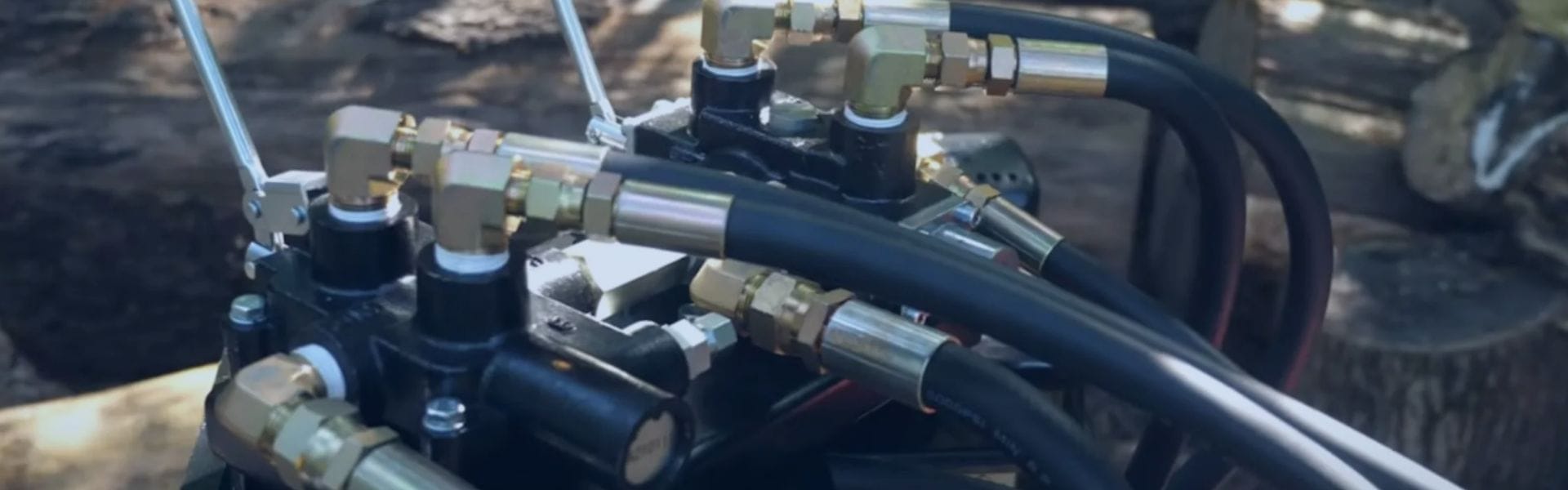
Hydraulic tubes play a critical role in fluid systems by facilitating the movement of hydraulic fluids under pressure. They serve as the primary pathway for transmitting energy, ensuring that hydraulic machinery operates smoothly and efficiently. Key functions of hydraulic tubes include:

Pressure Resistance: Tubes must withstand high pressures without failure, making material selection and design crucial.

Fluid Transport: Ensuring a continuous flow of hydraulic fluid is essential for system functionality and performance.

Safety Considerations: Properly maintained tubes prevent leaks and system failures, safeguarding both equipment and personnel.

Common Causes of Tube Cracks  

A. Poor Quality Welded Tubes

Explanation of Welding Processes

Welding is a critical process in the manufacturing of hydraulic tubes, especially in the production of welded tubes. Various welding techniques are employed, including Metal Inert Gas (MIG), Tungsten Inert Gas (TIG), and submerged arc welding. Each of these methods has specific advantages, influencing the overall quality of the weld. For instance, MIG welding is often faster and more versatile, making it suitable for various materials. In contrast, TIG welding provides greater control over the heat input, which is beneficial for thinner materials or those requiring precise welding.

The quality of the weld plays a crucial role in the structural integrity of hydraulic tubes. Poor welding practices can result in weak joints that are prone to cracking, particularly under the stress of hydraulic pressures. Factors such as welding speed, heat settings, and filler material can all impact the quality of the weld, making it imperative to adhere to established welding standards and practices.

Identification of Poor Weld Quality Indicators

Poor-quality welds can be a significant source of tube cracks. Several indicators can help identify these issues:

Visible Weld Seams: A pronounced or uneven weld seam may indicate poor fusion between the base metal and the filler material, increasing the likelihood of structural failure over time.

Inconsistent Weld Penetration: Uneven penetration can lead to weak spots in the weld that are more susceptible to stress concentrations, which may ultimately result in cracks.

Surface Imperfections: Issues such as craters, porosity, and slag inclusions can compromise the weld’s structural integrity. These imperfections create stress risers where cracks are more likely to initiate.

Regular inspection and adherence to quality standards, such as SAE J525, can help mitigate these issues. Employing advanced inspection techniques can further enhance the detection of poor weld quality before the tubes are put into service.

B. Excessive Cyclic Pressure

Definition of Cyclic Pressure and Its Effects

Cyclic pressure refers to the fluctuations in pressure that hydraulic systems experience during operation. These variations may arise from changes in load, fluid dynamics, or other operational conditions. Over time, these repeated pressure cycles can cause fatigue in the material, leading to cracks.

The phenomenon of cyclic fatigue is a crucial consideration in hydraulic system design. When materials are subjected to repeated loading and unloading cycles, they can develop microscopic cracks that grow progressively until they reach a critical size, resulting in catastrophic failure.

Factors Contributing to Cyclic Pressure in Hydraulic Systems

Several factors can contribute to excessive cyclic pressure:

System Design: Poorly designed hydraulic systems may expose tubes to unnecessary pressure variations, making them more vulnerable to fatigue. Engineers need to consider all potential pressure fluctuations during the design phase to minimize these risks.

Load Changes: Rapid changes in load can cause abrupt pressure spikes, placing additional stress on the tubes. This situation is especially common in dynamic systems where loads fluctuate frequently, such as in construction equipment or automotive applications.

Pump Performance: Inefficient or malfunctioning pumps can lead to irregular pressure outputs, exacerbating the effects of cyclic pressure. If pumps do not maintain consistent flow rates, they can create pressure surges that put extra stress on the tubing.

Addressing these factors through careful design, regular maintenance, and performance monitoring is vital to mitigating the risks associated with excessive cyclic pressure.

Longitudinal Tube Cracks

C. Incorrect Tube Wall Selection

Importance of Selecting Appropriate Wall Thickness

The wall thickness of hydraulic tubes is crucial for their performance and longevity. Thicker walls provide better resistance to internal pressures and external forces, thereby enhancing the tube’s ability to withstand operational stresses. It is essential to consider both the maximum working pressure and any potential pressure spikes when selecting wall thickness.

Material selection is equally important; different materials can withstand varying pressures and temperatures. Engineers must evaluate the specific requirements of their application to ensure that the chosen material and wall thickness will provide adequate support.

Consequences of Using Tubes with Insufficient Thickness

Using tubes with inadequate wall thickness can lead to several issues:

Increased Risk of Failure: Thinner walls are less capable of withstanding operational pressures, leading to premature cracks that can jeopardize the entire hydraulic system.

Deformation: Under high pressure, thin-walled tubes are more susceptible to deformation. This distortion can create stress concentrations that initiate cracks, particularly in high-load areas.

Reduced Safety Margin: A lack of appropriate wall thickness reduces the safety factors inherent in hydraulic system design. This decrease in margin increases the likelihood of catastrophic failure, which can result in costly repairs and downtime.

To avoid these pitfalls, engineers should rigorously evaluate their material choices and ensure that they are selecting tubes with appropriate wall thicknesses for their specific applications.

D. Environmental Factors

Impact of Temperature Fluctuations

Temperature variations can significantly affect the integrity of hydraulic tubes. High temperatures can lead to thermal expansion, causing materials to expand and potentially lose their shape. Conversely, low temperatures may lead to contraction, creating stress concentrations that can initiate cracks. Materials can also become more brittle at lower temperatures, further increasing their susceptibility to cracking.

In extreme environments, such as those involving significant temperature variations, selecting materials that can withstand these changes is critical. Manufacturers should consider thermal expansion coefficients when designing hydraulic systems to minimize the risk of cracks related to temperature fluctuations.

Influence of Pressure Spikes on Tube Integrity

Sudden pressure spikes can occur due to various reasons, such as valve closures, pump malfunctions, or flaws in system design. These spikes exert extreme forces on the tube walls, which can exceed the material’s fatigue limit. Consistent monitoring of pressure levels, along with the implementation of pressure relief systems, can help mitigate these risks.

To prevent damage from pressure spikes, hydraulic systems should be equipped with appropriate safety features, such as pressure relief valves and surge suppressors. Regular maintenance and performance assessments can also help identify potential vulnerabilities that may arise from environmental factors.

Symptoms and Detection of Tube Cracks  

A. Visual Signs of Longitudinal Cracks

Surface Cracking

Longitudinal cracks may manifest as visible lines or fissures along the length of the tube. These cracks often appear on the exterior surface and can vary in size from small hairline fractures to more pronounced openings. Operators should be vigilant for any signs of discoloration or surface irregularities that could indicate underlying issues.

Deformation of the Tube

Tubes exhibiting longitudinal cracks may also show signs of deformation, such as bulging or changes in diameter. This physical alteration can be indicative of internal stresses that compromise the tube’s integrity.
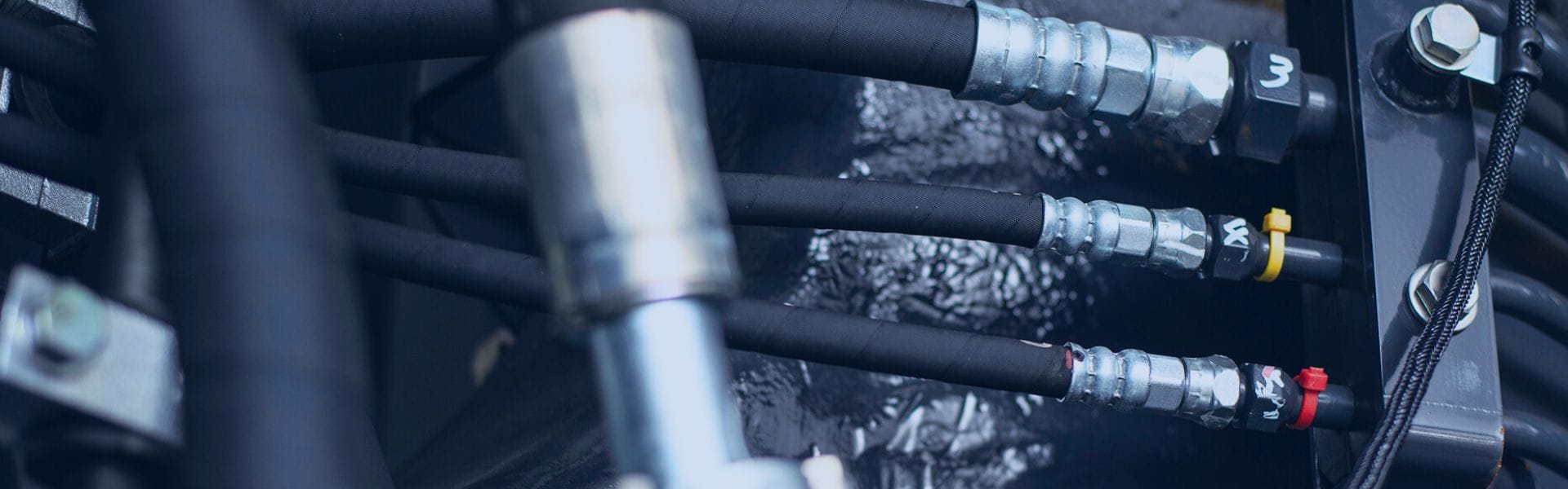
Fluid Leaks

The presence of fluid leaks near joints or connections can signal longitudinal cracks. Even minor leaks should be thoroughly investigated, as they may point to larger issues within the hydraulic system.

B. Methods for Detecting Cracks

Visual Inspection

Regular visual inspections are essential for the early detection of longitudinal cracks. Technicians should examine the entire length of the tube, paying close attention to weld seams and areas subject to stress.

Non-Destructive Testing (NDT)

Various NDT methods can be employed to detect cracks without damaging the tube. Common techniques include:

Ultrasonic Testing (UT): This method uses high-frequency sound waves to identify imperfections within the material. It is effective for detecting subsurface cracks.

Magnetic Particle Inspection (MPI): Suitable for ferromagnetic materials, MPI reveals surface and near-surface cracks by applying magnetic fields and observing particle accumulation.

Dye Penetrant Testing (DPT): A dye is applied to the surface of the tube, and after a set period, the excess dye is removed. Cracks will retain the dye, allowing for easy identification.

Pressure Testing

Conducting pressure tests can help identify weak points in the system. By gradually increasing the pressure and monitoring for leaks or abnormal readings, operators can pinpoint areas at risk of failure.

C. Importance of Regular Inspection and Maintenance

Preventive Maintenance

Regular inspections and maintenance are vital for the longevity of hydraulic systems. By proactively identifying and addressing potential issues, operators can prevent costly repairs and ensure system reliability.

Safety Assurance

Ensuring the integrity of hydraulic tubes is critical for the safety of operators and equipment. Longitudinal cracks can lead to catastrophic failures, posing risks of injury or damage. Regular monitoring helps mitigate these hazards.

Cost-Effectiveness

Investing in routine inspections can save money in the long run. Early detection of longitudinal cracks allows for timely repairs, reducing the risk of extensive damage that would require more significant resources and downtime.

Preventive Measures

A. Selecting High-Quality Tubes

Recommendations for Material Standards

Choosing high-quality tubes is paramount for ensuring the longevity and reliability of hydraulic systems. Material standards such as SAE J525 and SAE J524 provide guidelines for the manufacturing and testing of hydraulic tubing, ensuring they meet specific performance criteria. These standards cover aspects such as material composition, mechanical properties, and allowable tolerances.

Material Composition: It is essential to select tubes made from materials that can withstand the operational conditions of the hydraulic system. For instance, carbon steel or stainless steel are often preferred due to their strength and resistance to corrosion.

Mechanical Properties: Ensuring that the tube materials have adequate tensile strength, yield strength, and fatigue resistance is crucial. Compliance with industry standards ensures that tubes can handle the stresses associated with hydraulic applications.

Allowable Tolerances: Adhering to specified tolerances for dimensions and wall thickness is vital. Tubes that deviate from these tolerances may not perform as expected under pressure, leading to potential failures.

Benefits of Seamless Tubes versus Welded Tubes

The choice between seamless and welded tubes can significantly impact the performance of hydraulic systems:

Structural Integrity: Seamless tubes, which are produced without welds, offer superior structural integrity and are less prone to failure due to their uniform wall thickness. The absence of a weld seam minimizes stress concentration points, which are common sources of failure in welded tubes.

Pressure Rating: Seamless tubes generally have higher pressure ratings compared to welded tubes. This makes them more suitable for high-pressure applications, providing a safer option in demanding environments.

Manufacturing Variability: Welded tubes can exhibit variability in quality depending on the welding process and technique used. Seamless tubes, on the other hand, are manufactured in a continuous process that reduces the potential for defects.

Applications: In high-stress applications such as aerospace and heavy machinery, seamless tubes are often recommended to ensure reliability and safety.

By investing in high-quality tubes that meet established standards, operators can mitigate the risks of longitudinal cracks and extend the lifespan of their hydraulic systems.

Cutting sleeve hydraulic tube assembly Topa supplier

B. Managing Cyclic Pressure

Strategies for Monitoring and Controlling Pressure Fluctuations

Effectively managing cyclic pressure is crucial for preventing fatigue-related failures in hydraulic systems. Implementing robust monitoring and control strategies can help maintain pressure within safe limits.

Pressure Sensors: Installing pressure sensors throughout the hydraulic system allows for real-time monitoring of pressure levels. These sensors can trigger alarms or automatic shutdowns when pressure exceeds predetermined thresholds, preventing potential damage.

Data Logging: Utilizing data logging systems to record pressure fluctuations over time enables operators to analyze trends and identify patterns that may indicate potential issues. This information is invaluable for preventive maintenance and system optimization.

Regular Maintenance: Routine inspection and maintenance of hydraulic components can help identify wear and tear that may lead to pressure fluctuations. Regular checks of pumps, valves, and fittings ensure that they are functioning optimally and can handle the system’s demands.

Pressure Regulation: Implementing pressure regulation devices, such as relief valves and accumulators, helps manage sudden pressure spikes. Relief valves can divert excess fluid back to the reservoir when pressure exceeds safe levels, while accumulators can store energy during pressure surges.

Importance of System Design in Preventing Pressure Spikes

The design of hydraulic systems plays a critical role in preventing pressure spikes and ensuring consistent performance. A well-thought-out system design can reduce the likelihood of excessive cyclic pressure, ultimately safeguarding tube integrity.

Design Considerations: Engineers should consider factors such as fluid dynamics, load requirements, and potential pressure variations during the design phase. Incorporating features such as pressure relief systems, variable displacement pumps, and properly sized pipes can help manage pressures effectively.

Minimizing Restrictive Components: Ensuring that the hydraulic system has minimal restrictions, such as sharp bends or small-diameter pipes, can reduce turbulence and pressure drops. Smooth transitions and appropriately sized components contribute to better flow dynamics.

Component Selection: Choosing high-quality components that can withstand the operational pressures and environmental conditions is essential. This includes selecting robust pumps, valves, and fittings that align with the system’s pressure requirements.

Simulation and Testing: Utilizing computer simulations during the design phase allows engineers to predict how the system will behave under various conditions. Testing prototypes can provide valuable insights into potential pressure issues, enabling adjustments before full-scale production.

Repairing Longitudinal Tube Crack

A. Assessing the Extent of Damage

Before initiating any repair work, it is essential to thoroughly assess the extent of damage to the hydraulic tube. This step ensures that the appropriate repair method is chosen and helps prevent further issues down the line.

Visual Inspection: Start with a comprehensive visual inspection of the tube. Look for signs of cracking, deformation, or discoloration. Pay close attention to the weld seams and areas where cracks are most likely to occur.

Measuring Cracks: Use precise measuring tools, such as calipers or micrometers, to measure the length and width of the cracks. This quantification helps determine the severity of the damage and whether a repair is feasible or if replacement is necessary.

Wall Thickness Check: Conduct a wall thickness measurement at various points along the tube using ultrasonic thickness gauges. A significant reduction in wall thickness indicates that the structural integrity is compromised, necessitating replacement rather than repair.

Non-Destructive Testing (NDT): If possible, employ non-destructive testing methods such as dye penetrant testing or magnetic particle testing to identify internal cracks or defects that may not be visible externally. These methods provide a more comprehensive understanding of the tube’s condition.

B. Options for Repair vs. Replacement

Once the assessment is complete, consider the following options regarding repair or replacement:

Repair Options:

Welding: If the crack is minor and the wall thickness is still adequate, welding may be a viable option. However, this should only be performed by skilled welders familiar with hydraulic applications to ensure a proper seal and maintain tube integrity.

Patch Repair: In cases where welding is not feasible, patching the cracked area with a suitable material can provide a temporary fix. This method may involve using epoxy or other adhesives designed for high-pressure applications. However, patches should be considered a short-term solution.

Replacement:

If the crack is extensive or if the tube has significant wall thinning, replacement is often the best course of action. Replacing the entire tube not only ensures reliability but also mitigates the risk of recurring failures due to previously undetected damage.

Cost-Benefit Analysis: Weigh the costs of repair against the potential risks and long-term savings associated with replacing the tube. In many cases, opting for a replacement may be more cost-effective in the long run, especially if the system is critical and downtime needs to be minimized.

Conclusion

In summary, understanding the complexities of tube cracks is crucial for anyone involved in hydraulic systems. By being informed and proactive, we can maintain the integrity of our systems, safeguard our operations, and ultimately, achieve greater efficiency and safety in our hydraulic applications.


FAQ

What are longitudinal tube cracks?

Tube cracks are cracks that run lengthwise along the tube, typically caused by factors such as poor quality welding, excessive cyclic pressure, or incorrect tube wall thickness.

What causes tube cracks?

Common causes include poor-quality welded tubes, excessive cyclic pressure from load changes, incorrect tube wall selection, and environmental factors like temperature fluctuations and pressure spikes.

How can I detect tube cracks?

Detection methods include visual inspections for visible signs of cracking and using non-destructive testing techniques to identify cracks without damaging the tube.

What are the consequences of ignoring tube cracks?

Ignoring tube cracks can lead to leaks, system failures, safety hazards, and increased maintenance costs, potentially resulting in catastrophic incidents.

How can I prevent tube cracks?

Preventive measures include selecting high-quality tubes, monitoring and controlling cyclic pressure, conducting regular inspections, and ensuring proper system design to mitigate stress on the tubes.

What should I do if I find a longitudinal tube crack?

Assess the extent of the damage to determine if repair or replacement is needed. If repair is chosen, follow best practices to ensure proper sealing and structural integrity of the tube.

O-ring Failures Preventing Leaks in Hydraulic Systems banner

O-ring Failures: Preventing Leaks in Hydraulic Systems

When O-rings fail, the implications can be severe. Leaks resulting from O-ring failures can lead to operational inefficiencies, where hydraulic systems may not function at optimal performance levels, causing delays and increased energy consumption. Furthermore, the safety hazards associated with hydraulic fluid leaks can be significant; pressurized fluid can create dangerous working conditions, risking injury to personnel.

Understanding O-rings

A. Definition and Functionality

O-rings are circular sealing devices made from flexible materials, designed to fit into grooves and create a seal between two or more parts in a hydraulic system. When compressed, O-rings deform to fill the gap between mating surfaces, preventing fluid leakage and maintaining pressure. Their effectiveness relies on several factors, including material properties, groove design, and the specific application environment. O-rings can operate in a variety of conditions, effectively sealing both static and dynamic joints, making them essential for maintaining the integrity of hydraulic systems.

B. Types of O-rings

O-rings come in various materials and designs, each suited for specific applications and environmental conditions.

Nitrile (Buna-N): Known for its excellent resistance to petroleum-based fluids, nitrile is the most commonly used O-ring material in hydraulic applications. It offers good flexibility and is suitable for moderate temperatures.

Fluorocarbon (Viton): This material is highly resistant to chemicals and high temperatures, making it ideal for aggressive hydraulic fluids and environments. Fluorocarbon O-rings maintain their elasticity and sealing capabilities even under extreme conditions.

Polyurethane: Offering superior abrasion resistance, polyurethane O-rings are used in applications where wear and tear are significant concerns. They are also suitable for low-temperature applications.

Silicone: While not typically used for dynamic sealing due to lower tensile strength, silicone O-rings excel in high-temperature environments and are often found in applications where flexibility and thermal stability are crucial.

EPDM: Ethylene Propylene Diene Monomer O-rings are excellent for water and steam applications due to their exceptional weather resistance and ability to withstand heat.

Understanding these materials helps in selecting the right O-ring for specific hydraulic system needs.

FKM FFKM o ring factory

C. Common Applications in Hydraulic Systems

O-rings are utilized across a wide range of industries, reflecting their versatility and critical role in hydraulic systems. Some common applications include:

Automotive: O-rings are used in various automotive hydraulic systems, such as brakes and power steering, to ensure fluid containment and system reliability.

Manufacturing: Hydraulic presses and machinery rely on O-rings to prevent fluid leaks, which can disrupt operations and lead to costly downtime.

Construction: Equipment like excavators and backhoes utilize O-rings in hydraulic cylinders to maintain sealing integrity under high pressure.

Oil and Gas: O-rings play a vital role in subsea equipment, pipelines, and hydraulic fracturing applications, where they must withstand harsh environmental conditions and aggressive chemicals.

Identifying O-ring Failures

A. Common Signs of O-ring Failure

Identifying O-ring fails early is crucial to preventing significant system issues. Common visual indicators include:

Wear: Over time, O-rings can show signs of wear such as thinning or flat spots, indicating they are no longer providing an effective seal. This is often a result of excessive friction or improper installation.

Cracking: O-rings may develop cracks or splits due to exposure to harsh chemicals, extreme temperatures, or aging. Cracks can compromise the integrity of the seal, leading to leaks.

Deformation: If an O-ring appears squished, flattened, or misshapen, it may have been subjected to excessive compression or improper groove design. Deformed O-rings can lose their ability to seal effectively, causing fluid leakage.

Discoloration: Color changes can signal chemical degradation. For instance, O-rings made from nitrile may turn brown or harden when exposed to oil or heat, indicating potential failure.

Fluid Leakage: Visible fluid leaking from the connection points is one of the most obvious signs of O-ring failure. This indicates that the O-ring has lost its sealing capability.

O-Ring Failure Topa

B. Performance Issues Linked to O-ring Fail

O-ring fails can lead to various performance issues in hydraulic systems, including:

Reduced Efficiency: Leaks resulting from O-ring fails to cause a loss of hydraulic fluid, leading to decreased system pressure and efficiency. This can slow down machinery and reduce overall productivity.

Increased Maintenance Costs: Frequent O-ring fails necessitate regular inspections and replacements, increasing operational costs and downtime. This not only affects budgets but also impacts project timelines.

Safety Hazards: Leaking hydraulic fluid poses safety risks, especially in environments where flammable materials are present. Moreover, reduced hydraulic pressure can lead to equipment malfunctions, endangering personnel.

System Contamination: Leaks can introduce contaminants into the hydraulic system, leading to premature wear of components and system failure. Contaminated fluid can affect the performance of pumps, valves, and actuators.

Temperature Fluctuations: Inadequate sealing can lead to changes in system temperature, which can further exacerbate the degradation of O-rings and other components.

Causes of O-ring Failure

A. Improper Installation Techniques

The installation of O-rings is critical to their performance and longevity. Common mistakes during installation that can lead to failures include:

Incorrect Sizing: Using an O-ring that is too large or too small for the groove can prevent a proper seal. An oversized O-ring may not fit snugly, while an undersized O-ring may stretch excessively, leading to leaks.

Lack of Lubrication: Failing to lubricate the O-ring before installation can cause it to twist or pinch during assembly. Lubrication helps reduce friction and makes it easier to slide the O-ring into place without damaging it.

Misalignment: If the O-ring is not aligned properly within its groove, it may become pinched or compressed unevenly. Misalignment can lead to localized stress points, increasing the likelihood of cracks or deformations.

Over-tightening: Applying excessive torque during assembly can compress the O-ring beyond its elastic limits, leading to deformation and eventual failure. It’s essential to follow manufacturer specifications for torque settings.

Using Improper Tools: Using sharp or abrasive tools during installation can nick or damage the O-ring, compromising its sealing ability. Specialized tools should be used to handle O-rings safely.

Ignoring Groove Design: Each O-ring groove is designed with specific dimensions and shapes to accommodate the O-ring. Ignoring these specifications can lead to ineffective sealing and premature failure.

B. Environmental Factors

Environmental conditions play a significant role in O-ring performance and longevity. Key factors include:

Temperature Extremes: O-rings are sensitive to temperature fluctuations. High temperatures can cause elastomers to harden, while low temperatures can make them brittle. Operating outside the recommended temperature range can lead to loss of elasticity and increased wear.

Pressure Variations: Hydraulic systems often operate under high pressure. If the pressure exceeds the O-ring’s specifications, it can lead to extrusions or blowouts, compromising the seal.

Chemical Exposure: Certain chemicals can degrade O-ring materials. For example, exposure to hydrocarbons can cause nitrile O-rings to swell, while aggressive solvents can lead to cracking or dissolution. It’s crucial to select O-ring materials that are compatible with the operating environment.

Moisture and Humidity: High humidity can contribute to the degradation of certain O-ring materials, especially if they are not designed to handle moisture. Additionally, moisture can facilitate corrosion in metal components, affecting overall system integrity.

Ozone Exposure: Ozone can cause oxidation and degradation of rubber materials, leading to cracks and failures. O-ring materials should be chosen to resist ozone effects, particularly in outdoor applications.

C. Material Compatibility Issues

Material selection is critical in preventing O-ring fails. Issues can arise from:

Incorrect Material Choice: Selecting an O-ring material that does not match the application requirements can lead to rapid degradation. For instance, using a standard rubber O-ring in an application with high temperatures or chemical exposure will likely fail.

Incompatibility with Fluids: Different fluids have varying impacts on O-ring materials. Nitrile O-rings, for example, are excellent for petroleum-based fluids but may degrade in the presence of water or certain acids.

Inclusion Content: The presence of foreign materials or impurities in the O-ring can weaken its structure. For example, inclusions in the rubber can create stress points that lead to cracking or failure.

Processing Variability: The manufacturing process of O-rings can affect their performance. Variations in curing times, temperatures, and material blends can lead to inconsistencies in hardness and resilience.

Aging: Over time, all materials undergo aging, which can affect performance. For instance, prolonged exposure to oxygen and heat can result in hardening and loss of elasticity, leading to seal failure.

Sealing methods

D. Aging and Wear Over Time

O-rings experience natural wear and aging, which can compromise their sealing capabilities. Key points to consider include:

Cyclic Fatigue: O-rings in dynamic applications are subject to cyclic stresses that can lead to fatigue over time. Repeated compression and decompression can cause cracks and wear.

Environmental Aging: Exposure to UV light, oxygen, and other environmental factors accelerates the aging process. O-rings can harden, crack, or become discolored, indicating that they are reaching the end of their useful life.

Wear from Movement: In dynamic seals, movement against a surface can wear down the O-ring material. This wear can create gaps in the seal, leading to leaks.

Maintenance Neglect: Regular inspections and timely replacements are crucial. Neglecting maintenance can lead to unnoticed wear and eventual failure, resulting in costly downtimes.

Storage Conditions: Improper storage of O-rings can lead to premature aging. Exposure to heat, light, and moisture during storage can compromise their integrity before they are even installed.

Troubleshooting O-ring Issues

A. Systematic Approach to Diagnosing O-ring Problems

A structured approach to diagnosing O-ring problems can help identify the root causes effectively. Here’s a step-by-step guide:

Visual Inspection: Begin with a thorough visual examination of the O-ring and surrounding components. Look for obvious signs of wear, damage, or contamination. Check for cracks, deformation, or discoloration.

Check Installation: Confirm that the O-ring was installed correctly. Ensure it is seated properly in its groove without any twists or pinches. Verify that the correct size and material were used for the application.

Evaluate Operating Conditions: Review the operating conditions, including temperature, pressure, and fluid compatibility. Compare these conditions against the O-ring specifications to identify any discrepancies that could lead to failure.

Identify Performance Issues: Look for symptoms of O-ring failure, such as leaks or performance drops in the hydraulic system. Document any changes in pressure, fluid levels, or operational efficiency that may indicate a problem.

Conduct Pressure Testing: If leaks are suspected, perform pressure testing to confirm the presence of leaks. Use a pressure gauge to monitor changes in system pressure, which can indicate where a failure may be occurring.

Consult Historical Data: Review any maintenance records or historical data on the specific hydraulic system. Previous failures or replacements can provide insights into recurring issues or patterns that may help diagnose the current problem.

Engage with Manufacturers or Experts: If the issue remains unresolved, consult with the O-ring manufacturer or hydraulic system experts. They can provide specialized knowledge and insights based on similar cases.

B. Tools and Techniques for Detection

Utilizing the right tools and techniques can streamline the leak detection process and assess O-ring conditions effectively:

Leak Detection Fluids: These specialized fluids can be applied to suspected leak areas. Bubbles will form at the site of a leak, allowing for easy identification of O-ring failure points.

Ultrasonic Detectors: These devices can detect the high-frequency sound waves produced by escaping fluids. Ultrasonic detectors are especially useful in noisy environments where traditional detection methods may be hindered.

Pressure Gauges: Monitoring system pressure with gauges helps identify inconsistencies that may indicate O-ring issues. Sudden pressure drops can signal a leak or failure in the sealing system.

Borescopes and Endoscopes: These inspection tools allow for visual examination of hard-to-reach areas within the hydraulic system. They can help identify O-ring conditions in tight spaces without disassembly.

Thermal Imaging Cameras: These cameras can detect temperature variations caused by fluid leaks, as escaping fluids often exhibit different thermal profiles compared to the surrounding components.

Torque Wrenches: Using a torque wrench ensures that the O-ring connections are tightened to the specified levels. Over or under-torquing can compromise the seal, so proper tool usage is essential.

Micrometers and Calipers: Measuring tools can verify O-ring dimensions, ensuring they meet specifications and are not experiencing undue wear.

C. When to Replace O-rings

Determining when to replace O-rings rather than attempt repairs is crucial for maintaining system integrity. Consider the following guidelines:

Visible Damage: If the O-ring exhibits cracks, severe deformation, or significant wear, replacement is necessary. Damaged O-rings cannot provide an effective seal and pose a risk of leaks.

Signs of Aging: O-rings that have become hard, brittle, or discolored due to aging should be replaced. These changes indicate that the material properties have deteriorated, compromising the seal.

Repeated Failures: If an O-ring fails multiple times in a short period, it may be indicative of an underlying issue rather than a simple fault. In such cases, replacing the O-ring with a new one and addressing the root cause is essential.

Unacceptable Leak Rates: If the O-ring is leaking at a rate that exceeds acceptable levels, it is time for replacement. Conduct leak tests to quantify leakage and determine if the O-ring can be salvaged.

Environmental Changes: If the application environment has changed (e.g., higher temperatures or exposure to new chemicals), it may be necessary to replace O-rings with materials better suited for the new conditions.

Installation Mistakes: If improper installation has occurred, such as pinching or misalignment, the O-ring should be replaced. Attempting to reuse an improperly installed O-ring can lead to repeated failures.

Conclusion

Proactive measures, such as regular inspections, adherence to installation guidelines, and environmental considerations, can significantly mitigate the risk of leaks. Understanding the conditions that lead to O-ring degradation allows for informed decisions regarding material selection and operational practices. By prioritizing O-ring maintenance, operators can enhance safety, reduce downtime, and minimize operational costs associated with leaks.


FAQ

What is an O-ring, and what role does it play in hydraulic systems?

An O-ring is a circular sealing element made from elastomeric materials. It is used to create a seal between two parts, preventing leaks and maintaining system pressure in hydraulic applications.

What are common signs of O-ring failure?

Common signs include visible wear, cracking, deformation, and leaks around the sealing area. Reduced system performance and increased noise may also indicate O-ring issues.

What causes O-ring failures?

O-ring fails can result from improper installation, environmental factors (such as temperature and pressure), material compatibility issues, and natural aging or wear over time.

How can I troubleshoot O-ring problems in my hydraulic system?

Start with a systematic approach: inspect the O-ring visually for damage, check for proper installation, assess environmental conditions, and use tools like leak detection fluids or pressure gauges to identify issues.

When should I replace an O-ring instead of repairing it?

Replace an O-ring if it shows significant wear, cracking, or deformation that compromises the seal. If the O-ring has failed multiple times or is incompatible with the fluid, replacement is advisable.

What best practices can help prevent O-ring fails?

To prevent failures, ensure proper installation techniques, select compatible materials, conduct regular inspections, and maintain appropriate environmental conditions around the O-rings.

Metal vs Soft Seals banner

Metal vs Soft Seals: Choosing the Right Hydraulic Fitting

The two primary categories of seals used in hydraulic fittings are metal seals and soft seals. Metal seals, typically made from materials like stainless steel, are renowned for their durability and ability to endure extreme temperatures and pressures. In contrast, soft seals are crafted from elastomeric materials. These hydraulic fittings are designed to create a leak-tight seal with less torque, reducing the risk of damage during assembly.

Understanding Hydraulic Seals

A. Definition and Function of Hydraulic Seals

Hydraulic seals are critical components in hydraulic systems, designed to prevent fluid leakage and maintain system pressure. They act as barriers between different components, such as cylinders, pistons, and fittings, ensuring that hydraulic fluids remain contained within the system. The primary function of these seals is to create a tight, leak-proof connection that withstands the pressure and dynamics of the hydraulic system. Proper sealing is essential not only for the efficient operation of the system but also for safety, as leaks can lead to fluid loss, environmental hazards, and potential system failures.

Hydraulic seals must accommodate various factors, including temperature fluctuations, pressure changes, and chemical compatibility with the hydraulic fluid. They are designed to provide reliable performance under these conditions, preventing wear and prolonging the life of the hydraulic components they protect.

B. Importance of Sealing in Hydraulic Systems

The importance of sealing in hydraulic systems cannot be overstated. A well-sealed system ensures optimal performance and efficiency, as leaks can significantly impair hydraulic pressure and flow. This can lead to inadequate power transmission, slower response times, and increased wear on system components, ultimately affecting the reliability and longevity of the entire hydraulic system.

Moreover, effective sealing plays a crucial role in maintaining safety standards. Leaking fluids can create hazardous conditions, particularly in industrial settings where hydraulic systems are extensively used. Ensuring that seals are functioning correctly helps prevent accidents, spills, and contamination, thereby safeguarding both personnel and the environment.

In addition, the cost implications of leaks can be substantial. Fluid losses translate to increased operational costs, as the hydraulic system may require more frequent refills and maintenance. By investing in quality hydraulic seals, businesses can enhance their operational efficiency, reduce downtime, and lower maintenance expenses.

metal to metal seal Topa

C. Types of Hydraulic Seals

Hydraulic seals can be broadly classified into two main types: metal seals and soft seals. Each type has unique characteristics, advantages, and applications, making it essential for users to understand their options.

Metal Seals:

Metal seals are typically made from durable materials such as stainless steel or other alloys. They are engineered to withstand extreme temperatures, high pressures, and a wide range of chemicals, making them ideal for demanding environments. The primary advantage of metal seals is their longevity and reliability under severe conditions. They do not deform easily, maintaining their integrity over time, which makes them suitable for critical applications.

However, metal seals can also present some challenges. Their installation often requires precise torque settings to ensure an effective seal, which can complicate assembly and increase the risk of damage if overtightened. Additionally, while they perform well in static applications, metal seals can struggle in dynamic scenarios where movement and vibration are prevalent, potentially leading to leaks.

Soft Seals:

Soft seals, on the other hand, are constructed from elastomeric materials such as rubber or polymer blends. These seals provide excellent sealing performance due to their ability to compress and conform to the mating surfaces, creating a tight seal that is less prone to leakage. Soft seals excel in applications with moderate temperature ranges and less aggressive chemicals, making them versatile for many hydraulic systems.

One of the key benefits of soft seals is their ease of installation. They typically require less torque to achieve a proper seal, which simplifies assembly and reduces the risk of damaging the fittings. Additionally, their flexible nature allows them to absorb vibrations and slight movements, enhancing the reliability of the connection.

However, soft seals may have limitations regarding temperature and chemical resistance compared to metal seals. Over time, exposure to harsh conditions can lead to wear and potential failure, making them less suitable for certain high-demand applications.

Metal Seals: Features and Benefits

A. Composition and Construction

Metal seals are engineered from a variety of robust materials, primarily stainless steel, and other high-performance alloys. The choice of material is crucial, as it determines the seal’s ability to withstand extreme environmental conditions. The construction of metal seals often involves precision machining to create a precise fit between the sealing surfaces. This machining process ensures that the seals can maintain tight tolerances, which is essential for preventing leaks in high-pressure applications.

Metal seals can come in several designs, including flat rings, O-rings, and C-rings, each tailored for specific applications. The design of a metal seal often includes features that enhance its sealing performance, such as grooves or ridges that facilitate better contact with the mating surfaces. Some metal seals also incorporate specialized coatings or surface treatments to improve their resistance to wear and corrosion, further enhancing their longevity.

B. Advantages of Metal Seals

Extreme Temperature Resistance

One of the most significant advantages of metal seals is their ability to withstand extreme temperatures. Unlike soft seals, which may degrade or lose elasticity at high temperatures, metal seals retain their integrity even in severe thermal environments. This makes them ideal for applications in industries such as aerospace, oil and gas, and heavy machinery, where equipment can be exposed to high temperatures during operation. Metal seals can typically operate in temperature ranges from cryogenic levels up to several hundred degrees Celsius, depending on the material used.

Compatibility with Various Chemicals

Metal seals are inherently resistant to many chemicals, making them suitable for use in environments where aggressive fluids are present. They do not swell, degrade, or react chemically as some elastomers might. This chemical compatibility is crucial in industries like pharmaceuticals, chemicals, and food processing, where maintaining the purity of the fluid and ensuring safety is paramount. The versatility of metal seals allows them to be used in a wide range of applications, from hydraulic systems to chemical processing equipment.

Longevity and Durability

The durability of metal seals is another significant advantage. They are designed to withstand repeated cycles of pressure and temperature without significant wear or failure. Unlike soft seals, which may wear out and require replacement over time, metal seals can offer a longer service life, reducing the frequency of maintenance and replacement. This longevity is particularly beneficial in applications where access to components is limited or where downtime for maintenance can be costly.

C. Limitations of Metal Seals

Risk of Deformation

Despite their durability, metal seals are not immune to risks. One of the primary concerns is deformation, especially in high-pressure applications. Over time, or with improper installation, metal seals can deform, leading to compromised sealing performance. This risk is particularly pronounced in applications involving thermal cycling, where expansion and contraction can affect the integrity of the seal. Deformation can result in leaks, which not only impact system performance but also pose safety hazards.

Installation Challenges

Installing metal seals can be more complex than their soft seal counterparts. Achieving the proper torque is critical for ensuring a leak-proof connection; however, this requires precise calibration and experience. Excessive torque can lead to deformation, while insufficient torque may fail to create an adequate seal. This installation challenge can result in increased labor costs and the need for specialized tools or techniques, particularly in environments where space is limited.

Maintenance Considerations

While metal seals are durable, they do require periodic inspections to ensure their integrity. Over time, even the best-engineered seals can show signs of wear, particularly in dynamic applications where movement is prevalent. Maintenance of metal seals often involves checking for signs of deformation, wear, or corrosion, which can add to operational costs. Moreover, when maintenance is required, the process may involve significant disassembly of surrounding components, leading to longer downtime.

Soft Seals: Features and Benefits

A. Composition and Construction

Soft seals are primarily constructed from elastomeric materials, which are polymers that exhibit both elasticity and flexibility. Common materials used for soft seals include nitrile rubber (NBR), fluorocarbon (FKM), ethylene propylene diene monomer (EPDM), and silicone. Each of these materials has unique properties that make them suitable for specific applications, particularly in hydraulic systems.

The construction of soft seals typically involves forming the elastomeric material into various shapes, such as O-rings, gaskets, and custom molded seals. This versatility allows soft seals to be adapted for a wide range of fitting configurations and applications. The manufacturing process may include techniques such as compression molding or injection molding to achieve precise dimensions and tolerances, ensuring a reliable fit within hydraulic assemblies.

Soft seals are designed to create a tight seal through compression. When a fitting is assembled, the elastomeric material is compressed between the surfaces of the components, filling any microscopic gaps and creating a barrier against fluid leakage. This compression-based sealing mechanism is what allows soft seals to provide effective leak prevention while accommodating slight movements or misalignments in the hydraulic system.

O-ring face seal ISO 8434-3 Threads

B. Advantages of Soft Seals

Soft seals offer several distinct advantages over traditional metal seals, making them an increasingly popular choice for a variety of hydraulic applications.

Improved Sealing Performance:

One of the most significant benefits of soft seals is their superior sealing performance. The elastomeric materials used in soft seals can deform slightly under pressure, ensuring that they fill any voids between mating surfaces. This characteristic allows them to create a leak-tight seal even in less-than-perfect conditions. Over time, soft seals maintain their effectiveness, reducing the likelihood of leaks due to material fatigue or deformation, which can occur with metal seals.

Easier Installation:

Soft seals are typically easier to install than their metal counterparts. The design of soft seals allows for lower installation torque, meaning that less force is required to achieve a secure seal. This not only speeds up the assembly process but also minimizes the risk of over-tightening, which can lead to damage of the fitting or the seal itself. As a result, technicians can install soft seal fittings quickly and confidently, reducing downtime in hydraulic system setups.

Greater Flexibility and Resilience:

The inherent elasticity of soft seals provides them with a degree of flexibility that is particularly advantageous in dynamic applications. Soft seals can absorb vibrations and minor misalignments between components, making them less prone to leaks caused by movement or thermal expansion. This resilience allows soft seals to maintain effective sealing performance even in environments where the hydraulic components may experience significant movement or stress.

C. Limitations of Soft Seals

Despite their numerous advantages, soft seals do have certain limitations that users should consider when selecting sealing solutions for their hydraulic systems.

Temperature and Chemical Limitations:

While soft seals can handle a wide range of temperatures, they are generally more limited in extreme environments compared to metal seals. Each elastomeric material has specific temperature thresholds; for instance, NBR typically operates well in temperatures ranging from -40°C to +100°C, while FKM can handle higher temperatures but may be less effective in certain chemical environments. Users must carefully evaluate the temperature and chemical compatibility of soft seals based on the fluids used in their systems to prevent degradation or failure.

Potential for Wear Over Time:

Although soft seals offer excellent sealing performance initially, they can be more susceptible to wear and degradation over time compared to metal seals. Exposure to aggressive chemicals, high temperatures, and constant movement can lead to material breakdown, resulting in reduced sealing effectiveness. Regular inspection and maintenance are essential to identify any signs of wear and to replace seals as needed to maintain system integrity.

Transitioning from Metal to Soft Seals  

A. Steps for Transitioning

Transitioning from metal seals to soft seals in hydraulic systems involves a systematic approach to ensure compatibility and performance. The following steps can guide this process:

Assessment of Current Systems: Begin by evaluating the existing hydraulic system and identifying all components where metal seals are currently in use. This assessment should include a review of operating conditions, such as pressure, temperature, and the types of fluids handled.

Selecting Appropriate Soft Seals: Based on the assessment, select soft seals that are compatible with the existing fittings and suitable for the operational conditions. Consider factors such as material properties (e.g., NBR, FKM) and sealing configurations (e.g., O-rings, gaskets) to ensure optimal performance.

Testing and Validation: Before a full-scale implementation, conduct tests to validate the performance of soft seals in the existing system. This may involve installing a few soft seals in critical areas and monitoring their performance under actual operating conditions.

Full Implementation: Once testing is successful, proceed with the full implementation of soft seals across the hydraulic system, replacing metal seals with soft seals in all relevant applications.

B. Considerations and Best Practices During the Switch

When transitioning to soft seals, several considerations and best practices can help ensure a smooth process:

Compatibility Checks: Ensure that the selected soft seals are compatible with the existing hydraulic fittings and that they can withstand the chemical and temperature conditions of the application.

Installation Training: Provide training for technicians on the proper installation techniques for soft seals, emphasizing the importance of avoiding over-tightening and ensuring proper alignment during assembly.

Regular Monitoring: Implement a monitoring system to regularly check the performance of soft seals after installation. This can help identify any potential issues early and allow for timely maintenance or replacement.

Documentation: Maintain thorough documentation of the transition process, including specifications of the new seals, installation procedures, and performance monitoring results. This information can be invaluable for future maintenance and troubleshooting.

C. Potential Challenges and Solutions

Transitioning from metal to soft seals may present several challenges:

Performance Variability: Users may initially be concerned about the long-term performance of soft seals compared to metal seals. To mitigate this, conduct extensive testing and provide data on the reliability and lifespan of the selected soft seal materials.

Installation Errors: Improper installation can lead to leaks or seal failure. To address this, emphasize training and create clear guidelines for installation procedures. Consider utilizing visual aids or step-by-step manuals to assist technicians.

Material Degradation: Users may worry about the susceptibility of soft seals to wear and degradation. Choose high-quality materials that are well-suited for the specific application and emphasize the importance of regular maintenance checks to identify wear before it affects system performance.

Conclusion

Each application may necessitate a different approach, and the choice between metal and soft seals should be based on a thorough evaluation of the pros and cons of each option. By prioritizing reliable sealing performance, ease of installation, and long-term maintenance needs, engineers and technicians can optimize their hydraulic systems for enhanced efficiency and safety.


FAQ

What are hydraulic seals?

Hydraulic seals are components that prevent fluid leakage in hydraulic systems, ensuring efficient operation and protecting against contaminants.

What is the difference between metal seals and soft seals?

Metal seals are durable and suited for extreme conditions, while soft seals, made from elastomeric materials, offer better sealing performance and ease of installation.

What are the advantages of using soft seals?

Soft seals provide improved sealing capabilities, are easier to install, and offer greater flexibility and resilience under dynamic conditions.

Are there any limitations to soft seals?

Yes, soft seals can have temperature and chemical limitations and may wear over time, especially in harsh environments.

How can I transition from metal to soft seals?

Assess your current system, select compatible soft seals, conduct tests, and train technicians on proper installation techniques for a smooth transition.

When should I consider using soft seals in my hydraulic applications?

Consider soft seals for applications requiring reliable sealing performance, ease of installation, and flexibility, particularly in environments with vibrations or movements.

Leaking SAE J1926 and ISO 6149 Ports banner

Leaking SAE J1926 and ISO 6149 Ports: Troubleshooting Tips

SAE J1926 and ISO 6149 are standardized specifications for hydraulic ports that define the dimensions and characteristics necessary for reliable connections. SAE J1926 ports utilize O-ring seals to prevent leaks, while ISO 6149 ports focus on parallel and tapered threads for secure fittings.

Understanding SAE J1926 and ISO 6149 Ports

A. Definitions and Applications

SAE J1926 and ISO 6149 ports are standardized specifications used for hydraulic connections, ensuring compatibility and reliability across various applications. SAE J1926 pertains to O-ring boss fittings, which utilize O-rings to create a leak-tight seal. This design is essential for high-pressure applications, where even a small leak can lead to significant fluid loss and operational inefficiencies. The specification defines parameters such as thread dimensions, sealing surfaces, and torque requirements, enabling manufacturers to produce compatible components.

ISO 6149, on the other hand, includes specifications for both parallel and tapered threaded fittings. This standard emphasizes the use of precise thread dimensions to facilitate secure connections without relying solely on O-rings. The versatility of ISO 6149 fittings allows for a wide range of applications, from general hydraulic systems to specialized industrial equipment.

Both standards are essential for ensuring that hydraulic systems can be assembled with reliable connections that withstand varying pressures and environmental conditions.

SAE J1926-1

B. Importance of Proper Sealing in Hydraulic Systems

Proper sealing is critical in hydraulic systems for several reasons. First and foremost, effective seals prevent fluid leaks, which can compromise system efficiency and lead to operational failures. Leaks not only waste hydraulic fluid, resulting in increased costs but can also create hazardous conditions, such as slipping hazards in industrial settings or fire risks in systems using flammable fluids.

Moreover, maintaining proper sealing helps to ensure the longevity of hydraulic components. When seals fail, it can lead to increased wear on the fittings and connected components, resulting in more frequent replacements and higher maintenance costs. A well-sealed hydraulic system operates more efficiently, reducing the energy required to maintain pressure and flow, ultimately contributing to improved overall system performance.

C. Common Uses in Various Industries

The applications ISO 6149 and SAE J1926 ports span numerous industries, reflecting the versatility and importance of these hydraulic standards.

Automotive Industry: In automotive applications, these ports are frequently used in hydraulic systems for power steering, brake systems, and transmissions. The reliable sealing provided by ISO 6149 and SAE J1926 fittings is crucial for ensuring safety and performance in vehicles.

Aerospace Industry: Hydraulic systems in aerospace applications require high reliability and precision. ISO 6149 and SAE J1926 ports are used in various components, including landing gear systems, flight control systems, and hydraulic actuation systems, where performance and safety are paramount.

Manufacturing: In manufacturing settings, hydraulic systems power machinery such as presses, injection molding machines, and conveyor systems. The ability to maintain efficient and leak-free connections using standardized ports is essential for productivity and safety in these environments.

Construction: Heavy machinery used in construction, such as excavators and bulldozers, relies on hydraulic systems for operation. ISO 6149 and SAE J1926 ports facilitate reliable connections in these high-pressure systems, ensuring that equipment operates effectively in demanding conditions.

Agriculture: Hydraulic systems in agricultural equipment, like tractors and harvesters, utilize these ports to manage fluid dynamics for various functions, including steering and implement control. The robustness of these fittings contributes to the reliability required in agricultural applications.

Common Causes of Leaks in Hydraulic Ports

A. Overview of Typical Leak Sources

Leaks in hydraulic ports can arise from a variety of sources, and understanding these causes is critical for effective troubleshooting. Identifying the source of a leak not only aids in immediate repairs but also helps prevent future occurrences. Typical leak sources can generally be categorized into component wear, installation errors, manufacturing defects, and environmental influences. Each of these factors can compromise the integrity of hydraulic connections, leading to fluid loss and decreased system efficiency.

Preventing Leaks in Hydraulic Port

B. Detailed Examination of Common Causes

Damaged O-Rings

O-rings are essential components in hydraulic fittings that provide the seal between the fitting and the port. Damage to O-rings is a common cause of leaks and can occur due to several factors:

Wear and Tear: Over time, O-rings can degrade due to repeated exposure to high pressures, temperatures, and fluid chemicals. Cracks, deformation, or complete failure of the O-ring can create a leak path.

Installation Damage: Improper installation techniques, such as pinching or cutting the O-ring during assembly, can also lead to damage, resulting in leaks.

Chemical Compatibility: Using O-rings made from materials that are not compatible with the hydraulic fluid can cause them to swell, harden, or break down, compromising their sealing ability.

Improper Assembly and Torque Issues

Proper assembly is vital for ensuring a leak-free connection. Issues during the assembly process can lead to leaks, including:

Insufficient Torque: If fittings are not tightened to the specified torque levels, they may not seat properly against the sealing surfaces, leading to gaps that allow fluid to escape.

Over-Torquing: Conversely, excessive torque can deform fittings and damage O-rings, resulting in ineffective seals. Both insufficient and excessive torque can create leak paths that undermine system performance.

Incorrect Assembly Sequence: Not following the recommended assembly procedures can result in misalignment of components, further contributing to sealing failures.

Thread Manufacturing Defects

The quality of the threaded connections is critical for maintaining a secure seal. Manufacturing defects can contribute to leaks in the following ways:

Incorrect Thread Depth: If threads are not cut to the appropriate depth, fittings may not fully engage, preventing proper seating and leading to leaks.

Misalignment: Poorly manufactured threads can cause misalignment between the fitting and the port, compromising the seal and allowing fluid to escape.

Surface Irregularities: Any roughness or inconsistency on the thread surfaces can impede proper seating, further increasing the risk of leaks.

Foreign Contaminants and Debris

The presence of contaminants in the hydraulic system can significantly impact sealing performance. Common issues include:

Debris in Ports: Particles such as dirt, metal shavings, or old seal material can become lodged in the sealing surfaces, preventing effective contact between the O-ring and the port.

Fluid Contamination: Contaminants in hydraulic fluids can degrade seals and lead to premature wear, resulting in leaks.

Installation Contaminants: Failing to clean the fitting and port before assembly can introduce foreign materials that compromise the seal.

Environmental Factors (Temperature, Pressure Fluctuations)

External environmental conditions can affect the performance of hydraulic seals. Key factors include:

Temperature Extremes: Hydraulic systems often operate under a wide range of temperatures. Extreme heat can cause O-rings to harden and lose elasticity, while extreme cold can lead to brittleness, increasing the likelihood of leaks.

Pressure Fluctuations: Variations in pressure during operation can stress fittings and seals, potentially leading to deformation or failure over time. Systems that experience frequent pressure spikes are particularly vulnerable to leaks.

Vibration and Movement: Continuous vibration from machinery can cause fittings to loosen or O-rings to wear unevenly, leading to seal failures.

Inspection Techniques

A. Step-by-Step Guide to Inspecting Leaking Ports

Inspecting leaking hydraulic ports is essential for diagnosing issues and ensuring reliable performance. A systematic approach can help identify the source of leaks and prevent future problems. Here’s a step-by-step guide:

Depressurizing and Locking Out the System

Safety First: Before starting any inspection, ensure that the hydraulic system is completely depressurized. This can be done by shutting off the hydraulic pump and allowing the system to bleed off pressure naturally. Alternatively, a bleed valve can be used to safely release pressure.

Lockout Tagout (LOTO): Implement LOTO procedures to prevent accidental reactivation of the system during inspection. Place tags on control panels and locks on switches to ensure that the system remains inoperative while you work.

Visual Inspections for Damage and Wear

External Examination: Begin with a thorough visual inspection of the hydraulic port and surrounding components. Look for signs of fluid leaks, corrosion, or physical damage to the fitting and port.

Surface Conditions: Check for scratches, dents, or other irregularities on the port surface that could hinder sealing. Pay particular attention to the O-ring groove and sealing areas, as imperfections here can lead to leaks.

Checking O-Ring Surfaces for Scratches and Deformities

O-Ring Inspection: Remove the fitting to access the O-ring. Examine the O-ring for any signs of wear, such as cracks, cuts, or deformation. Even minor damage can compromise its sealing ability.

Surface Contact: Assess the O-ring’s contact surface on both the fitting and port. Ensure no contaminants or debris could affect the seal. If the O-ring shows signs of wear, replace it with a new one that is compatible with the hydraulic fluid.

Hydraulic Hose leak Testing

B. Importance of Checking the Leading Edge and Sealing Surfaces

The leading edge and sealing surfaces play a crucial role in the effectiveness of hydraulic fittings. Here’s why checking these areas is vital:

Leading Edge Examination: Inspect the edge of the fitting that enters the port. A sharp or poorly finished leading edge can cut or pinch the O-ring during installation, leading to leaks. If the edge is too sharp, consider smoothing it or using a lubricant during assembly to reduce the risk of O-ring damage.

Sealing Surface Condition: The sealing surface, where the O-ring makes contact, must be smooth and free of scratches. Any damage in this area can create a gap that allows fluid to escape. For effective sealing, both surfaces should be in complete contact, with no gaps or irregularities.

Visual Indicators: Look for concentric or circular scratches that might indicate previous leaks. While minor scratches may not be problematic, deeper or oblong scratches can compromise sealing effectiveness. If damage is significant, replacing the port or fitting may be necessary.

C. Using Lubricants During Installation to Prevent Damage

Using lubricants during the installation of hydraulic fittings can significantly reduce the risk of O-ring damage and improve sealing performance. Here are some key points regarding the use of lubricants:

Choosing the Right Lubricant: Select a lubricant that is compatible with both the hydraulic fluid and the materials used in the O-ring. Common options include silicone-based lubricants or specialized hydraulic assembly greases. Avoid petroleum-based lubricants, as they can degrade certain types of O-ring materials.

Application Technique: Apply a thin layer of lubricant to the O-ring before installation. This helps the O-ring slide into place more easily, reducing the chance of pinching or cutting during assembly. Ensure that the lubricant is evenly distributed and does not create a thick coating, which could impede sealing.

Benefits of Lubrication: Lubricants can help the O-ring maintain its elasticity and prevent it from sticking to the fitting or port surfaces during assembly. Additionally, lubricating the threads of the fitting can facilitate smoother installation and help achieve proper torque without excessive force.

Post-Installation Checks: After installation, verify that the fitting is correctly seated and that the O-ring is properly positioned. Perform a visual inspection to ensure that no lubricant has extruded from the seal area, indicating that the fitting is secure.

Proper Assembly Practices

A. Importance of Proper Fitting Assembly

Proper assembly of hydraulic fittings is critical for ensuring the integrity and performance of hydraulic systems. Inadequate assembly can lead to leaks, system failures, and increased maintenance costs. Here are several reasons why proper assembly is essential:

Leak Prevention: Properly assembled fittings create a secure seal that minimizes the risk of leaks. Leaks can lead to fluid loss, which not only affects system performance but also poses safety risks.

System Efficiency: Well-assembled fittings ensure optimal fluid flow and pressure management within the system. Any leaks or improper connections can reduce system efficiency and increase wear on components.

Component Longevity: Correct assembly practices help maintain the integrity of both the fitting and the port, reducing the likelihood of wear and damage over time. This leads to longer service life for both the hydraulic components and the overall system.

Safety Assurance: Hydraulic systems often operate under high pressure. Proper assembly is crucial for safety, preventing catastrophic failures that could result in injury or damage.

B. Detailed Assembly Instructions

Assembly of ISO 6149 and SAE J1926 fittings requires careful attention to detail. Here’s a step-by-step guide to ensure proper assembly:

Prepare the Components:

Inspect all components (fittings, ports, O-rings) for damage or wear before assembly.

Clean all sealing surfaces to remove dirt, debris, and old sealant materials.

Lubricate O-Rings:

Apply a compatible lubricant to the O-ring to facilitate installation and prevent damage during assembly.

Align Fitting with Port:

Position the fitting so that the O-ring is aligned with the sealing surface of the port. Avoid cross-threading by ensuring that the threads are aligned before engaging them.

Hand Tighten the Fitting:

Begin tightening the fitting by hand to ensure it is properly seated against the port. This initial step helps to avoid cross-threading and ensures that the O-ring is in the correct position.

Torque Application:

Use a torque wrench to tighten the fitting to the specified torque values (see the Torque Specifications section below). This ensures that the fitting is secure without over-tightening, which can damage the O-ring or the fitting.

Final Inspection:

After tightening, inspect the assembly for proper seating and alignment. Ensure that there are no gaps between the fitting and the port, and check that the O-ring is not pinched or damaged.

C. Common Mistakes to Avoid During Assembly

Several common mistakes can compromise the integrity of hydraulic fittings. Being aware of these pitfalls can help ensure a successful assembly:

Neglecting Component Inspection:

Failing to inspect fittings, ports, and O-rings for wear or damage can lead to leaks and failures. Always check components before assembly.

Improper Thread Engagement:

Cross-threading can occur if the fitting is not aligned correctly with the port. Ensure that threads are properly aligned before engaging.

Excessive Force:

Over-tightening fittings can damage the O-ring and fittings. Always adhere to specified torque values to avoid this issue.

Forgetting Lubrication:

Skipping the lubrication of O-rings can result in pinching or cutting during installation. Always use the appropriate lubricant to facilitate smooth assembly.

Ignoring Sealing Surface Condition:

Failing to clean and inspect sealing surfaces can result in inadequate sealing and leaks. Ensure all surfaces are clean and in good condition before assembly.

Rushing the Assembly Process:

Taking shortcuts or rushing through assembly can lead to mistakes. Allow adequate time to perform each step carefully.

D. Torque Specifications and Methods

Correct torque application is crucial for achieving a proper seal in hydraulic fittings. Here’s how to ensure that torque specifications are met during assembly:

Understanding Torque Specifications:

Torque specifications for ISO 6149 and SAE J1926 fittings can vary based on the size and material of the fitting. Always refer to manufacturer guidelines for specific torque values.

Using a Torque Wrench:

Employ a calibrated torque wrench to apply the specified torque. This tool ensures accuracy and consistency, which are vital for proper fitting assembly.

Incremental Tightening:

For larger fittings, consider using an incremental tightening approach. Tighten the fitting gradually in stages, allowing for an even distribution of force and reducing the risk of over-tightening.

Checking Final Torque:

After the initial tightening, it’s essential to check the final torque value. This ensures that the fitting is adequately secured without exceeding the recommended specifications.

Re-torquing:

In some cases, it may be necessary to re-torque fittings after the system has been pressurized and run for a period. This allows for the settling of the components and ensures that the seal remains intact.

Troubleshooting Steps  

A. Initial Troubleshooting Checklist for Leaking Ports

When dealing with leaking ISO 6149 and SAE J1926 ports, it’s essential to follow a systematic approach to identify and resolve the issue. Here’s a comprehensive initial troubleshooting checklist:

Depressurize the System:

Before performing any inspections, ensure the hydraulic system is completely depressurized and locked out to prevent accidents.

Visual Inspection:

Check for visible signs of leaks around the port and fitting area. Look for fluid accumulation, which can indicate the source of the leak.

Examine Sealing Surfaces:

Inspect the O-ring sealing surface for scratches, nicks, or other damage. Look for concentric scratches that may affect sealing integrity.

Inspect O-Rings:

Remove the fitting and examine the O-ring for deformation, cuts, or wear. A compromised O-ring is often the source of leaks.

Check Assembly Tightness:

Verify that the fitting is adequately tightened. Use a torque wrench to ensure it meets the manufacturer’s specifications.

Evaluate Component Alignment:

Ensure that the fitting is correctly seated against the port. Misalignment can lead to inadequate sealing and leaks.

Inspect Thread Quality:

Examine both the internal threads of the port and the external threads of the fitting for damage or manufacturing defects.

Review System Conditions:

Take note of the system’s operating temperature and pressure. Fluctuations outside recommended limits can contribute to leak issues.

B. How to Address Specific Issues Identified During Inspection

After completing the initial checklist, you may identify specific issues that require targeted solutions:

Damaged O-Rings:

If the O-ring is found to be damaged, replace it with a new one. Ensure proper lubrication during installation to prevent future damage.

Scratched Sealing Surfaces:

For scratches on the sealing surface, consider using fine-grit sandpaper to smooth out minor imperfections. However, if scratches are deep or extensive, replacing the port may be necessary.

Improper Tightening:

If the fitting is not properly tightened, reapply the correct torque using a torque wrench. Ensure that you do not exceed the specified torque to avoid damage.

Misalignment:

If misalignment is detected, check for obstructions that may prevent proper seating. Ensure that no components are interfering with the fitting’s insertion.

Thread Defects:

If threads are damaged, you may need to re-tap the port or fitting. If the damage is severe, replacing the component may be required.

Excessive System Pressure:

If the operating pressure is too high, consider adjusting the system pressure settings or evaluating the need for pressure relief valves to manage fluctuations.

C. When to Replace Components Versus Repairing Them

Determining whether to replace or repair components is crucial for maintaining hydraulic system integrity. Here are guidelines to help you make that decision:

Extent of Damage:

If the damage to an O-ring or sealing surface is minor, repair (e.g., replacing the O-ring or smoothing scratches) may be sufficient. For severe damage, such as deep scratches or cracks in the port, replacement is usually necessary.

Cost Considerations:

Evaluate the cost of replacement parts versus the potential costs of ongoing repairs. If a component frequently requires repair, it may be more economical to replace it.

Reliability Requirements:

In critical applications where reliability is paramount, opting for new components instead of repairs can provide peace of mind and reduce the risk of future failures.

Component Age:

Consider the age of the components. Older components may have reduced reliability, and investing in new parts can enhance system performance and longevity.

Manufacturer Recommendations:

Follow manufacturer guidelines regarding repairs and replacements. Some manufacturers may provide specific recommendations for components that should be replaced rather than repaired.

Inspection Frequency:

If you find yourself frequently inspecting and repairing a specific fitting or port, it might be a sign that replacement is warranted to ensure system integrity and reduce downtime.

Conclusion

Ultimately, maintaining hydraulic system integrity is an ongoing commitment that requires diligence, knowledge, and the right practices. By applying the insights and tips shared in this post, you can enhance the reliability and efficiency of your hydraulic systems, ensuring they operate smoothly and effectively in their respective applications.


FAQ

What are SAE J1926 and ISO 6149 ports?

SAE J1926 and ISO 6149 are standards for hydraulic ports that specify dimensions and sealing requirements for hydraulic fittings, ensuring compatibility and reliability in hydraulic systems.

What are common causes of leaks in hydraulic ports?

Common causes include damaged O-rings, improper assembly, thread defects, foreign contaminants, and environmental factors like temperature and pressure fluctuations.

How can I inspect for leaks in hydraulic ports?

Inspect by depressurizing the system, visually examining for damage, checking O-ring surfaces for scratches, and ensuring proper alignment and torque of the fitting.

What should I do if I find a damaged O-ring?

If the O-ring is damaged, replace it with a new one, ensuring proper lubrication during installation to avoid further damage.

How do I ensure proper assembly of hydraulic fittings?

Follow detailed assembly instructions, use the correct torque specifications, and ensure that the fitting is properly seated against the port to prevent leaks.

When should I replace a component instead of repairing it?

Replace components if the damage is severe, if ongoing repairs are cost-prohibitive, or if the component is old and likely to fail, compromising system integrity.

Importance of Correct Torque banner

Importance of Correct Torque: Ensuring Leak-Free Connections

Torque refers to the rotational force applied to fasteners, such as bolts and nuts, to achieve a specific level of tightness. In hydraulic systems, maintaining proper torque on tube connections is crucial for creating secure seals that prevent fluid leaks.

Understanding Torque and Its Role 

A. Definition of Torque

Torque is defined as the measure of rotational force applied to an object, typically described in units of Newton meters (Nm) or foot-pounds (ft-lbs). In mechanical engineering, it represents the effectiveness of a force to produce rotation around an axis. Mathematically, torque (τ) can be expressed as the product of force (F) and the distance (r) from the axis of rotation to the point where the force is applied: τ=F×r. This fundamental concept is crucial in applications involving fasteners and fittings, where the correct application of torque ensures that components are held securely together without compromising their integrity.

B. How Torque Affects Sealing

In hydraulic tube connections, the application of torque compresses the fitting and tubing materials, creating a tight seal. When a hydraulic fitting is torqued to the manufacturer’s specifications, it generates sufficient clamping force to deform the surfaces slightly, filling any microscopic gaps and imperfections. This deformation is key to achieving a leak-free connection. The appropriate amount of torque ensures that the seal is strong enough to withstand internal pressure without failing, while also preventing over-compression, which can lead to material fatigue or failure. The mechanics behind this sealing process emphasize the delicate balance between too little and too much torque, underscoring the importance of precise torque application in maintaining hydraulic integrity.

C. Common Misconceptions About Torque

There are several misconceptions surrounding torque that can lead to improper application and potential failures in hydraulic systems. One common myth is that “more torque is always better,” leading to over-tightening of fittings. In reality, excessive torque can deform fittings, leading to cracks and leaks. Another misconception is the belief that torque values are interchangeable across different materials and sizes. Each fitting type has specific torque requirements that depend on factors such as material properties, thread size, and intended application. Finally, some may assume that using lubricants can be disregarded when applying torque. However, lubricants can significantly affect torque values and must be considered to ensure accurate and effective fastening. By addressing these misconceptions, technicians can better understand the critical role of torque in maintaining leak-free hydraulic connections.

Identifying Proper Torque Specifications

A. Manufacturer Specifications

Adhering to manufacturer torque specifications is essential for ensuring the integrity and performance of hydraulic tube connections. Each fitting and component is designed with specific torque values that account for the materials used, the size of the threads, and the intended operating conditions. These specifications are determined through rigorous testing and engineering analysis to optimize sealing and performance while minimizing the risk of failure. Deviating from these guidelines can result in either under-torquing, which may lead to leaks, or over-torquing, which can cause deformation, material fatigue, or even catastrophic failure. Thus, referencing and strictly following the manufacturer’s torque settings is critical in maintaining the safety and efficiency of hydraulic systems.

Hydraulic Hose Assembly Torque size

B. Tools for Measuring Torque

To achieve the proper torque specifications, various tools are available, with torque wrenches being the most commonly used. There are several types of torque wrenches:

Click Torque Wrenches: These emit a clicking sound when the preset torque level is reached, providing audible feedback to the user. They are widely used for their simplicity and effectiveness.

Beam Torque Wrenches: These utilize a beam that bends when torque is applied, with a scale indicating the applied torque. They require careful reading and are less common in professional settings.

Digital Torque Wrenches: These provide precise torque measurements on a digital display and often feature programmable settings. They are ideal for applications requiring high accuracy.

Torque Angle Gauges: These are used in conjunction with a standard torque wrench to apply a specific angle of rotation after an initial torque value is set, providing additional precision.

Using the appropriate tool is vital to ensure that the correct torque is applied. Additionally, other tools such as torque multipliers can be beneficial for high-torque applications, allowing for easier and safer torque application without excessive force.

C. Importance of Calibration

Regular calibration of torque measurement tools is crucial for ensuring accurate and reliable torque application. Over time, tools can become worn or damaged, leading to inaccurate measurements that can jeopardize the integrity of connections. Calibration involves comparing the tool’s measurements against a known standard and making necessary adjustments to ensure precision.

Calibration should be performed at regular intervals, based on the tool’s usage frequency and manufacturer recommendations. This practice not only helps maintain accuracy but also extends the lifespan of the tools by identifying wear or damage early. Furthermore, ensuring that torque wrenches are calibrated before significant projects can prevent costly errors and enhance safety in hydraulic systems. By prioritizing calibration, technicians can trust that their torque applications meet the necessary specifications, ultimately leading to leak-free and efficient hydraulic connections.

Consequences of Improper Torque

A. Common Signs of Over-Torquing

Over-torquing occurs when excessive force is applied during the tightening of hydraulic fittings, leading to various detrimental effects. Recognizing the signs of over-torquing is essential for maintaining system integrity and preventing failures. Common indicators include:

Deformation of Fittings: One of the most immediate signs of over-torquing is visible deformation of the fitting or connecting components. This can manifest as flattened or bent sections where the fitting has been tightened. Such changes compromise the fitting’s ability to seal properly, increasing the risk of leaks.

Cracking: Over-torqued fittings may develop cracks, particularly in materials that are more brittle, such as certain metals or plastics. These cracks can start small and propagate rapidly under pressure, leading to sudden failure. Even minor hairline fractures can severely weaken the structural integrity of a fitting.

Material Fatigue: Continuous exposure to excessive torque can lead to material fatigue, a process where the material undergoes cyclic loading and unloading that ultimately leads to failure. Symptoms of fatigue may include discoloration or visible wear patterns on the fitting surface.

Thread Damage: Over-torquing can strip threads on both the fitting and the receiving end, making it difficult or impossible to create a reliable connection. Stripped threads not only compromise the integrity of the connection but may also require costly replacements or repairs.

Failure of Sealing Surfaces: In many hydraulic systems, fittings rely on specific sealing surfaces to maintain pressure. Over-torquing can deform these surfaces, leading to improper sealing. As a result, fluid may leak past the joint, causing operational inefficiencies and potential system damage.

Recognizing these signs is crucial for maintenance personnel to take corrective actions before a catastrophic failure occurs. Regular inspections and monitoring can help identify over-torqued connections early.

Hydraulic Hose Assembly Torque

B. Signs of Under-Torquing

Under-torquing refers to insufficient tightening of hydraulic fittings, which can lead to significant operational issues. The consequences of under-torquing can often be just as severe as those caused by over-torquing. Common signs include:

Fluid Leaks: The most apparent sign of under-torquing is the presence of fluid leaks at connection points. Insufficient torque may fail to compress the O-rings or sealing surfaces adequately, allowing hydraulic fluid to escape. This not only leads to fluid loss but can also create hazardous conditions in the working environment.

Pressure Fluctuations: In hydraulic systems, maintaining consistent pressure is crucial for efficient operation. Under-torqued fittings can cause pressure drops, leading to inconsistent performance. Operators may notice fluctuations in system pressure readings, indicating that the connection is not secure.

Operational Inefficiencies: When leaks occur due to under-torquing, the hydraulic system may have to work harder to maintain desired pressure levels. This can lead to increased wear and tear on components, decreased efficiency, and higher energy consumption. Over time, these inefficiencies can result in costly downtime and maintenance.

Increased Noise Levels: Leaks can also create unusual sounds in hydraulic systems. Under-torqued fittings may produce hissing or bubbling sounds as fluid escapes. This noise is often a clear indicator that further investigation is necessary.

Potential for Catastrophic Failure: In extreme cases, under-torqued fittings can lead to catastrophic failure, especially in high-pressure applications. If a fitting fails suddenly, it can result in the loss of control of hydraulic machinery, posing a severe safety risk to operators and nearby personnel.

Best Practices for Applying Proper Torque

A. Step-by-Step Torque Application Guide

Applying the correct torque to hydraulic fittings is critical for ensuring leak-free connections. Follow these steps for a reliable torque application process:

Gather Necessary Tools: Ensure you have the right tools on hand, including a calibrated torque wrench, a suitable socket or attachment for the fitting, and any required protective equipment (e.g., gloves, and safety goggles).

Inspect Fitting and Connection Surfaces: Thoroughly inspect both the hydraulic fitting and the surface it connects to for any signs of damage, debris, or corrosion. Clean surfaces as necessary to ensure a proper seal.

Initial Hand Tightening: Start by hand-tightening the fitting to ensure that it is seated correctly. This step helps align the threads and eliminates any cross-threading issues that could lead to improper torque application.

Apply Torque in a Controlled Manner: Using the torque wrench, apply torque gradually. Start by setting the wrench to a lower torque value (usually about 30-50% of the final specification) to establish a baseline seal.

Increase Torque Gradually: After achieving the initial torque, increase the setting to the manufacturer-recommended value. Turn the wrench slowly and smoothly, avoiding sudden movements that could cause over-torquing.

Use a Torque Pattern: For applications with multiple fittings, employ a specific torque pattern (discussed in section B) to ensure an even distribution of pressure and avoid misalignment.

Double-Check Torque: Once the final torque is reached, re-check the torque using the wrench to confirm that the setting is maintained. If adjustments are necessary, always loosen the fitting slightly before re-tightening to the correct specification.

Document the Process: Keep records of the torque values used for each fitting. Documentation can help with future maintenance and inspections.

By following these steps meticulously, technicians can ensure that torque is applied correctly, thus preventing leaks and failures in hydraulic systems.

B. Recommended Torque Patterns

In multi-bolt applications, the sequence in which torque is applied plays a significant role in achieving a secure seal. Here are key points regarding torque patterns:

Importance of Torque Sequence: Applying torque in a specific sequence helps distribute stress evenly across all fittings. This is particularly crucial for large assemblies where uneven pressure can lead to warping or leaks.

Common Torque Patterns:

Criss-Cross Pattern: For circular or rectangular bolt arrangements, start from the center and work outward in a criss-cross fashion. This approach minimizes stress concentration and ensures uniformity.

Star Pattern: Similar to the criss-cross method, the star pattern is effective for flanged connections. Start with one bolt, then move to the opposite bolt, followed by adjacent ones. This sequence helps maintain an even seal.

Incremental Steps: Apply torque in increments, gradually increasing to the final specification. This method allows for adjustments if any misalignment occurs during the tightening process.

Visual Aids: Utilize diagrams or charts to illustrate recommended torque sequences. Having a visual reference can help technicians remember the correct order, especially in complex installations.

By adhering to these torque patterns, technicians can enhance the reliability of tube connections, reducing the risk of leaks and system failures.

C. Regular Maintenance and Inspections

To maintain the integrity of torque settings and ensure leak-free operations, regular maintenance and inspections are essential. Here are the best practices for ongoing checks:

Routine Inspections: Schedule regular inspections of hydraulic fittings and connections, particularly in high-pressure systems. This helps identify any signs of wear, damage, or loosening before they lead to failures.

Re-torquing: Periodically re-check torque values, especially after initial installation or following significant operational changes (e.g., pressure adjustments, temperature fluctuations). Re-torquing helps ensure that connections remain secure over time.

Visual Checks for Signs of Wear: During inspections, look for visual indicators such as fluid leaks, corrosion, or signs of fatigue. Early detection can prevent more significant issues from developing.

Record-Keeping: Maintain a detailed log of inspections, including torque values, observed conditions, and any corrective actions taken. This documentation serves as a valuable reference for future maintenance activities.

Tool Calibration: Regularly calibrate torque wrenches and other measuring tools to ensure accuracy. Using improperly calibrated tools can lead to incorrect torque application, increasing the risk of leaks.

Troubleshooting Torque-Related Issues  

A. Diagnosing Torque Problems

Identifying torque-related failures in hydraulic systems requires a systematic approach to accurately diagnose the issue. Follow these steps:

Initial Observation: Begin by visually inspecting the hydraulic fittings for any obvious signs of leaks or damage. Look for fluid pooling, discoloration, or corrosion around the fittings, which may indicate a problem.

Pressure Testing: Conduct a pressure test to check for leaks. By applying pressure to the system and monitoring for pressure drops, you can determine if a fitting is leaking. This test can help isolate the problem areas.

Torque Verification: Use a calibrated torque wrench to verify that the fittings are tightened to the manufacturer’s specifications. If the torque is below the recommended levels, this may be a direct cause of leaks.

Sequential Tightening Check: If multiple fittings are involved, verify that they were tightened in the proper sequence. Any irregularities in the tightening order may contribute to misalignment or leaks.

Review Historical Data: Check maintenance logs for past torque values and any previous issues with the fittings. Patterns may emerge that can help identify if torque-related problems are recurring.

Environmental Assessment: Consider the operating environment. Factors such as temperature fluctuations, vibrations, or exposure to corrosive substances can exacerbate torque issues and contribute to fitting failures.

Functional Testing: Finally, conduct functional tests on the hydraulic system to observe how it performs under load. Sudden pressure drops or fluctuations may indicate torque-related problems.

By systematically following these steps, technicians can effectively diagnose torque-related issues and implement appropriate corrective measures.

B. Tools and Techniques for Diagnosis

Several tools and techniques can assist in diagnosing torque-related issues in existing connections:

Torque Wrench: A calibrated torque wrench is essential for measuring the tightness of fittings accurately. This tool ensures that fittings are torqued to the correct specifications, reducing the risk of leaks.

Pressure Gauges: These devices measure the pressure within the hydraulic system. A sudden pressure drop can signal a leak or failure in the fittings, warranting further investigation.

Leak Detection Fluids: These special fluids change color or create bubbles when they come into contact with escaping fluids. Applying leak detection fluid around fittings can help pinpoint the source of a leak.

Ultrasonic Leak Detectors: These advanced devices can detect high-frequency sounds produced by gas or fluid leaks. They are especially useful in noisy environments where traditional methods may fail.

Visual Inspection Tools: Use magnifying glasses or borescopes to closely inspect hydraulic fittings for cracks, wear, or corrosion that may not be visible to the naked eye.

Vibration Analysis Tools: Monitoring vibrations in hydraulic systems can help identify misalignments or issues related to torque. Changes in vibration patterns can indicate a developing problem.

Conclusion

By committing to these practices, you can enhance the reliability and safety of your hydraulic systems, ultimately contributing to smoother operations and reduced operational costs. Let’s work together to ensure our systems remain leak-free and perform at their best.


FAQ

What is torque, and why is it important in hydraulic systems?

Torque is a measure of rotational force applied to fasteners. In hydraulic systems, proper torque ensures tight and secure connections, preventing leaks and maintaining system efficiency.

What are the consequences of improper torque?

Improper torque can lead to leaks, system failures, material fatigue, and safety hazards, potentially resulting in costly downtime and maintenance.

How can I determine the correct torque specifications for my system?

Always refer to the manufacturer’s specifications for torque settings. These guidelines are based on the specific materials and design of the fittings.

What tools can I use to measure torque accurately?

Torque wrenches are the primary tools for measuring and applying the correct torque. Digital torque wrenches can provide more precise readings.

What signs indicate that torque may be improperly applied?

Common signs of over-torquing include deformation or cracking of fittings, while under-torquing may result in visible leaks or unstable pressure readings.

How often should I check and calibrate my torque tools?

It’s recommended to calibrate torque tools regularly, typically at least once a year, or more frequently if used extensively in critical applications.

Causes of Hydraulic Fitting Leaks banner

Causes of Hydraulic Fitting Leaks: Misalignment and Misfit

Misalignment and misfits in hydraulic fittings are among the leading causes of leaks. Misalignment occurs when fittings are not properly aligned, which can lead to uneven stress distribution and compromise seal integrity. Misfit refers to the improper fitting of components due to size discrepancies or compatibility issues, which can prevent effective sealing.

Identifying Misalignment and Misfit Issues

A. Visual Indicators of Misalignment

Identifying visual signs of misalignment in hydraulic fittings is crucial for early intervention. Key indicators include:

Uneven Gaps: Check for irregular spacing between the fitting and connecting components. A proper fit should exhibit consistent gaps; uneven spaces often indicate misalignment.

Wear Patterns: Inspect the surfaces of fittings for unusual wear. Misaligned connections can lead to concentrated wear on one side, suggesting improper contact and sealing.

Deformation: Look for signs of deformation in the fitting itself, such as bending or twisting, which can be caused by improper alignment during installation or operation.

Leaks in Hydraulic Ports

B. Performance Indicators

Performance issues can serve as critical indicators of misalignment and misfits in hydraulic systems. Key performance indicators include:

Pressure Fluctuations: Monitor for inconsistent hydraulic pressure readings. Misalignment often leads to fluctuations that can compromise system performance and lead to inefficient operation.

Fluid Leakage: A visible leak at the fitting connection is a direct sign of misalignment or misfit. Continuous leaks can result in significant fluid loss and decreased operational efficiency.

Increased Operating Temperature: Misaligned fittings can cause excessive friction, leading to higher temperatures in the system. Monitoring temperature changes can help detect underlying misalignment issues.

Identifying Misalignment and Misfit Issues

A. Visual Indicators of Misalignment

Recognizing visual signs of misalignment in hydraulic fittings is essential for effective maintenance and prevention of leaks. Key indicators to observe include:

Uneven Gaps: Inspect the fitting connections for irregular spacing. Properly aligned fittings should exhibit uniform gaps. Uneven gaps can signal misalignment, leading to inadequate sealing and potential leaks.

Wear Patterns: Examine the surfaces of fittings and hoses for unusual wear. Misalignment often results in concentrated wear on one side of the fitting, indicating that it is not seated correctly. Look for shiny spots or grooves that suggest excessive friction.

Deformation: Identify any physical deformation of the fittings themselves. This can include bending, twisting, or flattening the connection points. Such changes often arise from improper alignment during installation or operation and can compromise the integrity of the fitting.

B. Performance Indicators

In addition to visual cues, monitoring performance indicators is crucial for detecting misalignment and misfits in hydraulic systems. Significant performance issues include:

Pressure Fluctuations: Regularly check hydraulic pressure readings. Misalignment can lead to erratic pressure levels, which may affect the overall system efficiency. Consistent pressure drops or spikes often indicate that fittings are not properly aligned.

Fluid Leakage: The most direct sign of misalignment is visible fluid leakage at the fitting connection. A leak can be a result of inadequate sealing caused by misalignment or misfit. Continuous leaks not only waste hydraulic fluid but also increase operational costs and environmental concerns.

Increased Operating Temperature: Monitor the temperature of the hydraulic system. Misaligned fittings can create excessive friction, leading to higher operating temperatures. Elevated temperatures can degrade system components and result in premature failure.

Causes of Misalignment in Hydraulic Fittings  

A. Installation Errors

Improper installation is one of the leading causes of misalignment in hydraulic fittings. Common mistakes during the fitting installation process include:

Incorrect Torque Application: Applying inadequate or excessive torque when tightening fittings can lead to misalignment. Insufficient torque may not secure the fitting properly while over-torquing can distort the fitting or the components it connects to, creating uneven surfaces and gaps.

Failure to Follow Manufacturer Guidelines: Each hydraulic fitting comes with specific installation guidelines, including recommended torque settings and alignment procedures. Ignoring these guidelines can result in misaligned fittings and increased wear over time.

Inadequate Preparation of Surfaces: The surfaces where fittings connect must be clean and free of debris, corrosion, or damage. Failure to prepare these surfaces properly can lead to improper seating of the fittings, causing leaks and misalignment.

Neglecting Alignment Tools: Using alignment tools or jigs during installation is crucial. Skipping this step can result in fittings that appear connected but are not properly aligned, leading to future operational problems.

B. Vibration and Movement

Hydraulic systems are often subject to dynamic conditions that can affect the alignment of fittings. Key factors include:

Operational Vibration: Continuous operation of hydraulic systems can generate significant vibrations. These vibrations can cause fittings to loosen over time, especially if they are not installed securely. Loose fittings are more susceptible to misalignment and subsequent leaks.

Mechanical Movement: Equipment that undergoes regular movement, such as mobile machinery or vehicles, can shift hydraulic lines and fittings. This movement can alter the positioning of the fittings, leading to misalignment.

Dynamic Loading: Fluctuations in pressure and load can induce stresses on hydraulic fittings. Sudden changes in system dynamics can shift the alignment of fittings, especially if they are not adequately supported.

C. Thermal Expansion

Temperature variations in hydraulic systems can have a profound impact on fitting alignment. Important aspects to consider include:

Differential Expansion: Different materials expand at varying rates when exposed to heat. If hydraulic fittings are made from materials with significantly different coefficients of thermal expansion, temperature changes can cause one fitting to expand more than the other, leading to misalignment.

Heat Generation from Operation: Hydraulic systems generate heat during operation, which can exacerbate thermal expansion issues. When fittings are subjected to elevated temperatures, the likelihood of misalignment increases, particularly in systems that cycle between heating and cooling.

Impact on Seals: Thermal expansion can also affect the seals used in conjunction with hydraulic fittings. Misalignment due to thermal effects can compromise seal integrity, leading to leaks and performance issues.

Hydraulic Fitting Fluid Leaks

D. Structural Issues

The integrity of the structural components where hydraulic fittings are mounted plays a critical role in maintaining alignment. Factors include:

Mounting Surface Integrity: Fittings must be mounted on stable and level surfaces. If the mounting surface is warped, uneven, or damaged, it can lead to misalignment during installation and operation. Regular inspection of mounting surfaces is essential to ensure proper fitting alignment.

Frame Integrity: The overall integrity of the machinery or structure housing the hydraulic system can also affect fitting alignment. Structural issues such as bending, cracking, or other forms of degradation can cause fittings to become misaligned over time.

Support and Bracing: Proper support and bracing of hydraulic lines and fittings are necessary to prevent movement that could lead to misalignment. Inadequate support can allow fittings to shift, particularly in mobile or vibrating equipment.

Causes of Misfit in Hydraulic Fittings  

A. Incompatible Fitting Types

Matching fittings is crucial for ensuring leak-free and efficient hydraulic connections. Key points to consider include:

Types of Fittings: Hydraulic systems use various types of fittings (e.g., compression, flare, push-to-connect) designed for specific applications. Using an incompatible fitting type can lead to misalignment and improper sealing, increasing the risk of leaks.

Thread Standards: Different standards exist for threaded fittings (e.g., NPT, BSP, JIC). Mixing these thread types can result in poor engagement and sealing failure, leading to hydraulic fluid leaks. Ensuring compatibility between thread standards is vital for system integrity.

Size Compatibility: Fittings must match the diameter and size of the connected components. Using fittings that are too small or too large can cause misfits, leading to weak connections and leaks. Regular checks on fitting sizes can prevent these issues.

Connection Method: Each fitting type has a specific connection method (e.g., welding, crimping, screwing). Failing to use the correct connection method can lead to improper fits, potentially resulting in catastrophic failures under pressure.

B. Material Degradation

Material properties play a significant role in the fit of hydraulic fittings. Important aspects include:

Corrosion: Exposure to corrosive environments can degrade fitting materials, altering their dimensions and leading to misfit issues. For instance, stainless steel fittings may corrode in the presence of chloride ions, resulting in compromised sealing surfaces.

Wear: Over time, fittings experience wear due to friction, pressure cycling, and environmental factors. This wear can change the dimensions of the fittings, making them incompatible with their connected components. Regular inspections for signs of wear can help identify potential problems early.

Surface Damage: Scratches, dents, or other forms of surface damage can affect the integrity of the fit. Even minor imperfections can lead to gaps that cause leaks. Proper handling and storage of fittings are essential to prevent surface damage.

Temperature Effects: Extreme temperatures can lead to material degradation over time. High temperatures may soften materials, while low temperatures can make them brittle. Understanding the thermal limits of materials used in hydraulic fittings is crucial for maintaining proper fits.

C. Manufacturing Tolerances

Variations in manufacturing processes can significantly impact the fit of hydraulic fittings. Consider the following points:

Tolerance Levels: Each fitting is manufactured with specific tolerance levels that define how closely the actual dimensions align with the intended design. Tight tolerances are necessary for ensuring a secure fit, while loose tolerances can lead to misfits.

Quality Control: Inconsistent quality control during the manufacturing process can result in fittings that do not meet specified tolerances. Regular audits of manufacturing processes and suppliers can help ensure the reliability of components used in hydraulic systems.

Batch Variability: Fittings produced in different batches may exhibit variations in dimensions due to changes in raw materials or manufacturing processes. It is important to source fittings from the same batch or supplier to minimize discrepancies.

Impact of Machining Processes: Processes such as machining, forging, or molding can introduce variations in dimensions. Understanding these processes and their potential effects on fitting tolerances is crucial for selecting the right components.

hose Ferrule fail

D. Aging Components

The aging of hydraulic fittings and associated components can lead to misfits over time. Important factors include:

Fatigue: Repeated cycling of hydraulic pressure can lead to fatigue in fittings. This fatigue can manifest as micro-cracking or dimensional changes, ultimately resulting in misfits and compromised sealing capabilities.

Environmental Exposure: Long-term exposure to environmental factors, such as UV light, moisture, and temperature fluctuations, can degrade the properties of fittings. This degradation can alter their dimensions and lead to poor fits.

Seal Degradation: O-rings and other sealing components that age or wear out can contribute to fitting misalignment. Ensuring that all sealing elements are replaced according to the manufacturer’s recommendations is vital for maintaining proper fits.

Consequences of Misalignment and Misfit

A. Leak Development

Misalignment and misfit in hydraulic fittings can lead to leak development through several mechanisms:

Inadequate Sealing: When fittings are misaligned or do not fit correctly, the sealing surfaces may not make proper contact. This can create gaps that allow hydraulic fluid to escape under pressure. Even minor misalignments can significantly impact sealing effectiveness, leading to gradual fluid loss over time.

Increased Pressure on Seals: Misalignment can subject seals to uneven pressure distributions. As hydraulic pressure fluctuates, these uneven forces can exacerbate wear on seals, leading to premature failure and increased susceptibility to leaks.

Dynamic Movement: In hydraulic systems, components often experience vibrations and movement during operation. Misalignment can amplify these effects, causing fittings to shift and leading to further deterioration of the seal integrity. Continuous movement can eventually result in catastrophic leaks.

Stress Concentration: Misfits create localized stress concentrations in fittings and connected components. These stresses can lead to cracking or deformation, particularly in high-pressure environments. Once a crack forms, leaks can develop rapidly, sometimes without warning.

B. Operational Inefficiencies

The operational inefficiencies resulting from misalignment and misfit can have far-reaching consequences:

Reduced Hydraulic Efficiency: Leaks caused by misalignment or misfit reduce the overall efficiency of hydraulic systems. Fluid loss directly translates to a decrease in the system’s ability to perform its intended function, which can compromise productivity.

Increased Energy Consumption: As hydraulic systems work harder to compensate for fluid loss, energy consumption rises. This results in higher operating costs and can lead to increased wear on system components, further exacerbating efficiency losses.

Flow Disruptions: Misaligned fittings can disrupt fluid flow, leading to turbulence and increased pressure drops. These disruptions can cause erratic system behavior, making it difficult to maintain stable operations.

Need for Frequent Maintenance: Systems experiencing leaks or inefficiencies often require more frequent maintenance checks and repairs. This not only adds to operational costs but also increases downtime, further impacting productivity.

C. Safety Hazards

Leaks in hydraulic systems present significant safety hazards that must be addressed:

Fluid Hazards: Hydraulic fluids can be toxic, flammable, or environmentally harmful. Leaks pose risks to personnel working near the system, as exposure to these fluids can lead to health issues or hazardous situations, particularly in confined spaces.

Pressure-Related Risks: High-pressure hydraulic systems are inherently dangerous. Leaks can result in sudden pressure drops or failures that may lead to catastrophic events, including equipment damage or even injuries to personnel.

Environmental Concerns: Hydraulic fluid leaks can contaminate the surrounding environment, posing risks to local ecosystems and water supplies. This can lead to regulatory fines and necessitate costly cleanup efforts.

Operational Disruptions: Safety incidents resulting from leaks can lead to operational shutdowns, investigations, and loss of productivity. Addressing safety concerns is paramount to maintaining not only operational integrity but also compliance with safety regulations.

Conclusion

Proactive management of hydraulic fittings is vital for maintaining system integrity and preventing leaks. Regular inspections and maintenance can help identify early signs of misalignment or misfit, allowing for timely corrections before they escalate into more serious issues. Implementing rigorous installation protocols and utilizing compatible components can greatly reduce the risk of misalignment and misfit, thereby enhancing overall system performance.


FAQ

What are the main causes of hydraulic fitting leaks?

The primary causes of hydraulic fitting leaks include misalignment, misfit, improper installation, material degradation, and environmental factors such as temperature and vibration.

How can I identify misalignment in hydraulic fittings?

Signs of misalignment include uneven gaps between fittings, unusual wear patterns, and inconsistent performance in hydraulic pressure and efficiency.

What is the difference between misalignment and misfit?

Misalignment refers to fittings not being properly aligned during installation, while misfit occurs when incompatible fitting types are used or when components degrade over time, affecting their fit.

How can I prevent leaks caused by misalignment and misfit?

To prevent leaks, ensure proper installation techniques, use compatible fittings, conduct regular inspections, and address any structural issues in the mounting surfaces.

What are the safety hazards associated with hydraulic fitting leaking?

Hydraulic fitting leaking can lead to fluid spills, increased pressure loss, and system failures, posing risks to personnel and equipment, especially in high-pressure environments.

When should I replace the hydraulic fittings?

Fittings should be replaced if there are visible signs of wear, corrosion, or damage if they are not properly sealed, or if they have been involved in any incident that could compromise their integrity.

Tubing and Swivel Nut Leak Diagnosis banner

Tubing and Swivel Nut Leak Diagnosis: A Comprehensive Guide

Leaks in hydraulic systems can lead to significant operational inefficiencies and safety hazards. When fluid escapes from a system, it not only reduces the overall pressure and performance but can also cause system components to work harder to compensate for the lost fluid, leading to increased wear and tear.

Understanding Tubing and Swivel Nut Fittings  

A. Types of Tubing and Fittings

Hydraulic systems utilize various types of tubing and fittings, each designed for specific applications and pressure requirements. Common types of tubing include:

Seamless Tubing: Manufactured from solid round billets, seamless tubing is strong and resistant to high pressures. It’s often used in high-stress applications where integrity is crucial.

Welded Tubing: This type involves joining metal pieces together using welding techniques. While generally more cost-effective than seamless tubing, welded tubing may have lower pressure ratings due to potential weak spots at the welds.

Flexible Hoses: These are often used in applications requiring movement or vibration. Made from rubber or synthetic materials, flexible hoses can accommodate bends without compromising the flow of hydraulic fluid.

Swivel nuts come in various designs, such as an o-ring face seal (ORFS) and 37-degree flare fittings. ORFS fittings create a reliable seal using an o-ring and are less prone to leakage compared to traditional flared fittings. Flare fittings provide a metal-to-metal seal and are commonly used in high-pressure applications.

Mastering Metric Tube Fittings

B. How Connections Work

Swivel nuts and tubing fittings function by creating a secure and leak-proof connection. The mechanics of these connections can be broken down as follows:

Alignment: Proper alignment of the tubing with the fitting is crucial. The tubing must fit snugly against the sealing surface of the fitting to avoid creating a gap where leaks can occur.

Compression: When the swivel nut is tightened, it compresses the tubing against the fitting, forcing the sealing surfaces together. This compression generates the necessary clamping force to maintain a tight seal.

Sealing Mechanism: In ORFS fittings, the o-ring is held in place by the fitting’s design, allowing for metal-to-metal contact outside the o-ring groove. This design helps maintain the o-ring’s integrity, reducing the risk of extrusion or damage during operation.

Understanding these mechanics is essential for ensuring that connections are assembled correctly, which directly impacts the reliability of the hydraulic system.

C. Common Applications

Tubing and swivel nut fittings are prevalent in numerous industries and applications, including:

Manufacturing: Hydraulic systems are integral to machinery such as presses, injection molding machines, and conveyors. Reliable tubing and fittings are crucial for maintaining consistent operation.

Construction: Hydraulic equipment like excavators, bulldozers, and cranes rely on these connections to ensure fluid transfer and functionality under demanding conditions.

Automotive: In automotive applications, hydraulic systems are used for power steering, brake systems, and lift mechanisms, all of which depend on high-quality tubing and fittings for performance and safety.

Oil and Gas: Hydraulic systems used in drilling, extraction, and processing rely on secure connections to prevent leaks in critical operations.

Identifying Leak Symptoms

A. Visual Indicators of Leaks

Identifying leaks in hydraulic systems often begins with observing visual indicators. Here are some common signs to look for:

Fluid Pooling: The accumulation of hydraulic fluid beneath connections or hoses is one of the most straightforward signs of a leak. The presence of fluid can indicate a slow but persistent leak that may worsen over time.

Discoloration: Fluid leaks can lead to discoloration on surfaces surrounding the tubing or fittings. This may manifest as dark spots or streaks on the tubing, fittings, or the surface beneath. Discoloration can also occur due to the degradation of materials, indicating potential leaks or failures.

Corrosion: Prolonged exposure to hydraulic fluids can cause corrosion on metal fittings and tubing. Signs of corrosion, such as rust or flaking, not only suggest a leak but can also indicate the need for immediate replacement to prevent further damage.

Staining on Surrounding Surfaces: Leaked fluids may stain surrounding materials, such as hoses, mounting brackets, or the ground. These stains can serve as visual cues for leak detection and may vary in color depending on the type of hydraulic fluid used.

Tubing and Swivel Nut Leak Diagnosis

B. Auditory Signs

In addition to visual cues, auditory signs can help diagnose leaks in hydraulic systems. Some common sounds to listen for include:

Hissing: A hissing sound often indicates pressurized fluid escaping from a small opening. This sound can be more pronounced during system operation and may help pinpoint the leak’s location.

Bubbling: If air is being drawn into the hydraulic system due to a leak, it may create a bubbling sound as the fluid circulates. This can signal that the integrity of the seal is compromised, leading to potential air contamination in the system.

Whistling or Squealing: These sounds can occur if hydraulic fluid is forced through a restricted area due to a leak. The turbulence created by the leak can lead to unusual noises, signaling that the system may be under stress.

Change in Normal Operational Sounds: Any deviation from the typical operational sounds of the hydraulic system can indicate a problem. If the system is noisier than usual or sounds erratic, it could be a symptom of a leak affecting performance.

C. Performance Issues

Leaks can significantly impact the performance of hydraulic systems, leading to various operational challenges:

Pressure Instability: Leaks can cause fluctuations in hydraulic pressure, resulting in inconsistent performance. Pressure drops can affect the system’s ability to maintain adequate force or speed, which may compromise the efficiency of hydraulic machinery.

Decreased Efficiency: When leaks occur, the hydraulic system may need to work harder to maintain performance levels. This can lead to increased energy consumption and wear on system components, ultimately shortening their lifespan.

Increased Maintenance Needs: Leaks often lead to more frequent maintenance and inspections, which can be costly and time-consuming. If left unaddressed, they can escalate into more severe issues that require extensive repairs.

Potential for Catastrophic Failure: In severe cases, leaks can lead to complete system failure, resulting in costly downtime and potential safety hazards. This emphasizes the importance of early detection and prompt repairs to prevent minor leaks from escalating into major issues.

Tubing and Swivel Nut Leak Reasons

A. Inadequate Torque and Improper Assembly

One of the primary causes of leaks in tubing and swivel nut connections is inadequate torque during assembly. Torque is the measure of rotational force applied to a fastener, and it plays a critical role in achieving a secure connection that can withstand internal pressure and vibrations.

Understanding Torque Requirements: Each type of fitting and tube requires a specific amount of torque to ensure that the joint is properly sealed. Insufficient torque can lead to gaps between the sealing surfaces, allowing hydraulic fluid to escape. Over time, even slight pressure fluctuations can exacerbate this issue, resulting in leaks.

Effects of Improper Assembly: Improper assembly practices, such as failing to follow manufacturer guidelines or using incorrect tools, can also contribute to inadequate torque. If the assembly process is rushed or lacks attention to detail, it can result in loose fittings that fail under pressure.

Monitoring and Maintenance: Regular inspection and monitoring of torque levels can help prevent leaks. Utilizing torque wrenches and adhering to the recommended torque specifications during installation can significantly reduce the risk of inadequate sealing.

B. Misalignment or Improper Fit

Alignment plays a crucial role in the integrity of tubing and swivel nut connections. Misalignment or improper fit can create leak paths, leading to significant performance issues.

Importance of Proper Alignment: For a seal to function correctly, the tube must be aligned with the fitting’s sealing surface before tightening the nut. If the tube is misaligned, it can create stress points that compromise the seal. This misalignment can be due to improper bending of the tube or incorrect assembly practices.

Consequences of Improper Fit: An improper fit can occur if the tube is cut incorrectly, resulting in gaps that the fitting nut cannot close adequately. When these gaps exist, they form weak points where hydraulic fluid can escape, leading to leaks.

Preventive Measures: To ensure proper alignment, technicians should visually inspect the connections before tightening. Making necessary adjustments to the tube’s position can prevent future leaks and maintain the integrity of the system.

C. O-ring Damage

O-rings are essential components in tubing and swivel nut connections, acting as seals that prevent fluid leakage. Damage to O-rings can significantly impact system performance.

Types of O-ring Damage:

Extrusion: Occurs when internal pressure forces the O-ring out of its groove, often due to improper assembly or excessive pressure.

Pinching or Deformation: Can happen during installation if the O-ring is not properly seated, leading to visible deformations that compromise sealing ability.

Wear and Tear: Over time, O-rings can wear out due to exposure to hydraulic fluids, temperature fluctuations, and environmental factors, resulting in cracks or brittleness.

Implications of O-ring Damage: A damaged O-ring can create a leak path, allowing fluid to escape and potentially leading to system inefficiencies. Regular inspection and replacement of O-rings can help maintain system integrity.

Best Practices for O-ring Management: To minimize the risk of O-ring damage, operators should ensure proper material selection, adhere to correct installation procedures, and regularly inspect O-rings for signs of wear.

O-Ring Failure Topa

D. Braze Overflow and Fitting Damage

Issues related to brazing and damaged fittings can also lead to leaks in hydraulic systems.

Braising Issues: Brazing is a process used to join metal components through the use of a filler metal. However, improper brazing techniques can result in braze overflow, where excess filler material obstructs the sealing surfaces. This overflow can prevent proper sealing and lead to leaks.

Identifying Fitting Damage: Damage to fittings can range from minor scratches to significant cracks. Even small imperfections on sealing surfaces can prevent a proper seal, allowing hydraulic fluid to escape. Regular inspection of fittings for damage during installation and maintenance can help identify potential issues before they lead to leaks.

Repair and Replacement Considerations: If braze overflow or fitting damage is identified, it may be necessary to re-braze or replace the affected components. Using high-quality fittings and adhering to recommended brazing practices can help minimize these issues.

Troubleshooting Leak Sources

A. Systematic Diagnosis Steps

Diagnosing leaks in tubing and swivel nut connections requires a structured approach to ensure all potential issues are identified and resolved effectively.

Initial Inspection: Start with a visual inspection of the tubing and fittings. Look for obvious signs of leakage, such as fluid pooling around connections, discoloration, or corrosion. Take note of any unusual sounds that may indicate a leak.

Isolate the System: Shut down the hydraulic system and relieve any pressure to ensure safety during the diagnosis process. Lockout/tagout procedures should be followed to prevent accidental activation.

Check Connections: Inspect all connections, focusing on the swivel nuts and tubing joints. Verify that the fittings are properly tightened and that there are no signs of misalignment or improper fit.

Evaluate Torque Settings: Use a torque wrench to confirm that all fittings are tightened to the manufacturer’s specified torque. If the torque is inadequate, retighten as necessary.

Inspect O-rings: Remove the fittings and examine the O-rings for signs of damage, wear, or improper seating. Replace any O-rings that appear compromised.

Test for Leaks: Reassemble the connections and conduct a leak test. This can be done by re-pressurizing the system and observing the connections for leaks.

Identify the Root Cause: If a leak is detected, use the information gathered during the inspection to identify the root cause. Consider factors such as assembly practices, alignment, and potential fitting damage.

Document Findings: Keep a detailed record of the diagnosis process, including any observations and actions taken. This documentation can help in future troubleshooting efforts.

B. Tools and Techniques for Leak Detection

Utilizing the right tools and techniques is essential for effective leak detection. Here are some commonly used methods:

Pressure Gauges: These instruments measure the pressure in the hydraulic system. A sudden pressure drop can indicate a leak. Installing pressure gauges at strategic points can help pinpoint areas where leaks are occurring.

Leak Detection Fluids: These fluids are applied to suspected leak areas. They create bubbles when in contact with escaping fluid, providing a clear visual indication of a leak. This method is simple and effective for small leaks.

Ultrasonic Detectors: These devices detect high-frequency sounds generated by leaks. They are especially useful for identifying leaks that are not visible to the naked eye. Ultrasonic detectors can pinpoint the exact location of a leak, even in noisy environments.

Thermal Imaging Cameras: These cameras can identify temperature differences in components, which may indicate fluid leakage. They are particularly useful for larger systems where traditional methods may be less effective.

Smoke Testers: In some cases, introducing smoke into the system can help visualize leak paths. The smoke will escape from any leaks, providing a clear indication of where attention is needed.

Fluorescent Dye Testing: Adding fluorescent dye to the hydraulic fluid can make leaks more visible. When exposed to UV light, the dye will glow, highlighting the source of the leak.

C. Importance of Safety Measures

Safety should always be a priority when diagnosing leaks in hydraulic systems. Here are key precautions to consider:

Lockout/Tagout Procedures: Before starting any diagnosis, ensure the system is properly shut down and locked out to prevent accidental operation. Tagging the equipment helps communicate that maintenance is in progress.

Personal Protective Equipment (PPE): Technicians should wear appropriate PPE, including gloves, safety glasses, and protective clothing. This helps protect against exposure to hydraulic fluids, which can be hazardous.

Pressure Relief: Always relieve pressure from the hydraulic system before beginning any inspection or repair work. This minimizes the risk of fluid spray, which can cause injury.

Proper Ventilation: Ensure that the work area is well-ventilated, especially when using leak detection fluids or performing tasks that may release fumes.

Tool Safety: Use tools correctly and ensure they are in good working condition. Improper use of tools can lead to accidents and injuries.

Emergency Preparedness: Have a plan in place for responding to leaks or accidents. This includes having spill kits and first aid supplies readily accessible.

Repairing Leaks: Options and Best Practices

A. Repair vs Replacement Decisions

When addressing leaks in tubing and swivel nut connections, a critical decision must be made: whether to repair or replace the affected components. Here are key considerations for making this choice:

Extent of Damage: Evaluate the severity of the damage. Minor leaks, such as those caused by improper torque or misalignment, may be effectively repaired. However, if fittings or tubing exhibit significant damage, such as cracks, severe corrosion, or extensive wear, replacement is often the safer and more reliable option.

Cost Analysis: Consider the cost implications of repair versus replacement. Repairs might initially seem more economical, but if they require frequent attention or result in ongoing leaks, the cumulative costs may exceed those of replacing the component outright.

Downtime Considerations: Assess the impact of repair versus replacement on system downtime. Repairs can often be completed more quickly, reducing operational interruptions. However, if a component’s reliability is in question, a replacement might provide long-term peace of mind and avoid future downtime.

B. Best Practices for Making Repairs

If a decision to repair is made, following best practices will help ensure the repair is effective and long-lasting. Here are key techniques for repairing leaks in tubing and swivel nut connections:

Proper Cleaning: Before making any repairs, clean the affected area thoroughly. Remove any debris, oil, or residue that may interfere with the repair process. This will ensure that any sealing materials adhere properly.

Re-Torqueing Connections: If the leak is suspected to be due to inadequate torque, re-torque the connections according to the manufacturer’s specifications. Use a calibrated torque wrench to ensure that the correct pressure is applied without overtightening.

Replacing O-rings: If O-ring damage is identified, replace the O-rings with ones that meet the correct specifications (size, material, and durometer). Ensure that the new O-rings are seated correctly in their grooves before reassembling the fittings.

Sealing Compounds: For certain applications, using a thread sealing compound may help improve the seal between threaded fittings. However, it’s essential to use the appropriate type of sealant, as some compounds may not be compatible with hydraulic fluids.

Braze or Weld Repair: In some cases, braze or weld repairs may be viable for damaged tubing or fittings. This requires specialized skills and equipment, so it’s advisable to engage a qualified technician for this type of repair.

Conducting Pressure Tests: After making repairs, perform pressure tests to verify that the leak has been successfully resolved. This will help ensure that the system is safe for operation before returning it to service.

C. Importance of Following Manufacturer Guidelines

Adhering to manufacturer guidelines is crucial when repairing leaks in hydraulic systems. Here’s why:

Safety Assurance: Manufacturers design their components based on rigorous testing and safety standards. Following their guidelines ensures that repairs are performed in a manner that maintains the integrity and safety of the system.

Warranty Considerations: Many manufacturers have specific stipulations regarding warranty coverage. Not following their guidelines during repairs could void warranties, leaving you responsible for future failures.

Performance Reliability: Manufacturer guidelines provide insights into the best practices for installation, repair, and maintenance. Following these recommendations helps ensure that the system operates reliably and efficiently over time.

Compatibility and Materials: Manufacturers specify materials and components that are compatible with their systems. Using non-approved replacements can lead to incompatibility issues, resulting in further leaks or damage.

Conclusion

Leak diagnosis is not merely a reactive measure; it is a proactive strategy that is essential for the longevity and efficiency of hydraulic systems. Identifying and addressing leaks promptly can prevent costly downtime and safety hazards, protecting both the equipment and personnel involved. By prioritizing leak management, organizations can significantly enhance their operational reliability, ensuring that hydraulic systems function at optimal levels.


FAQ

What are common signs of a leak in tubing and swivel nut connections?

Common signs include visible fluid pooling, discoloration, corrosion on fittings, and unusual sounds like hissing or bubbling. Performance issues, such as fluctuating pressure, may also indicate a leak.

What causes leaks in hydraulic systems?

Leaks can be caused by inadequate torque, misalignment of fittings, damaged O-rings, braze overflow, and physical damage to the fittings themselves.

How can I diagnose a leak in my hydraulic system?

Start by visually inspecting for signs of leaks, listening for unusual sounds, and checking system performance. Use tools like pressure gauges and leak detection fluid for a thorough diagnosis.

Should I repair or replace a leaking fitting?

The decision depends on the extent of the damage. If the fitting or tubing can be repaired effectively and safely, it may be a suitable option. However, if damage is extensive, replacement is often more reliable.

What safety precautions should I take when diagnosing leaks?

Always power down the equipment, wear appropriate personal protective equipment (PPE), and ensure the area is secure. Be aware of potential hazards, such as pressurized fluids.

How can I prevent leaks in my hydraulic system?

Implement best practices like regular maintenance, proper assembly techniques, using high-quality components, and following manufacturer guidelines to ensure the integrity of your connections.

DIN 3852 vs ISO 1179 Threads banne

DIN 3852 vs ISO 1179 Threads: A Comprehensive Guide

DIN 3852 and ISO 1179 are two standards that govern the design and implementation of threaded ports and stud ends in hydraulic systems, specifically focusing on BSPP (British Standard Pipe Parallel) threads. Both standards outline detailed specifications for various sealing methods, including elastomeric seals and metal-to-metal connections, thereby enabling manufacturers and engineers to select the appropriate fittings for their applications.

Understanding DIN 3852  

A. Definition and Scope

DIN 3852 is a standard established by the Deutsches Institut für Normung (DIN) that outlines specifications for threaded ports and sealing methods used in hydraulic systems. This standard is crucial for ensuring compatibility and reliability in hydraulic connections, which are essential for maintaining the integrity and efficiency of hydraulic circuits. DIN 3852 encompasses various types of threaded connections and sealing techniques, providing guidelines that help manufacturers and engineers design systems that meet specific performance criteria.

B. Historical Background

The development of DIN 3852 can be traced back to the growing need for standardized components in hydraulic technology during the late 20th century. As hydraulic systems became increasingly complex and widespread across various industries, it became evident that inconsistencies in fitting designs could lead to performance issues, leaks, and system failures. In response, the DIN committee worked to create a comprehensive set of standards, culminating in the establishment of DIN 3852. This standard has since evolved to incorporate advancements in technology and materials, ensuring it remains relevant in contemporary hydraulic applications.

DIN 3852 Threads

C. Parts of DIN 3852

DIN 3852 is divided into several parts, each addressing different aspects of hydraulic connections:

DIN 3852-1: Threaded Ports

This part specifies the dimensions, tolerances, and performance requirements for threaded ports in hydraulic systems. It primarily focuses on the compatibility of different thread types, ensuring that components can be easily assembled without the risk of leaks or mechanical failure. DIN 3852-1 promotes uniformity in design, which is essential for manufacturers and users alike.

DIN 3852-2: Captive Seal Stud Ends

DIN 3852-2 outlines the specifications for captive seal stud ends. These connections utilize a seal that is held in place to prevent movement during assembly. This design enhances reliability by minimizing the chances of misalignment or leakage. The standard provides detailed guidelines on dimensions and materials, ensuring that captive seal stud ends can withstand the pressures and conditions typical of hydraulic systems.

DIN 3852-3: O-ring Seal Stud Ends

This part addresses the design and performance requirements for O-ring seal stud ends, which are commonly used in hydraulic applications. O-ring seals provide an effective means of preventing fluid leakage by compressing against the mating surface. DIN 3852-3 specifies the dimensions, tolerances, and materials suitable for O-ring seals, emphasizing their role in enhancing the reliability and longevity of hydraulic systems.

DIN 3852-4: Metal-to-Metal Sealing

DIN 3852-4 focuses on metal-to-metal sealing techniques, which are critical in high-pressure applications where conventional sealing methods may not suffice. This part outlines the requirements for the design and construction of metal-to-metal seals, ensuring they can provide a reliable barrier against fluid leakage even under extreme conditions. By defining these standards, DIN 3852-4 helps manufacturers create components that are robust and capable of maintaining performance in demanding environments.

Understanding ISO 1179  

A. Definition and Scope

ISO 1179 is an international standard developed by the International Organization for Standardization (ISO) that specifies requirements for threaded ports and sealing methods used in hydraulic systems. This standard aims to ensure compatibility and interoperability between components manufactured by different companies, facilitating the assembly and maintenance of hydraulic circuits. ISO 1179 encompasses various connection types, emphasizing the importance of reliable sealing solutions to prevent leaks and maintain system integrity.

B. Historical Background

The creation of ISO 1179 arose from the need for a unified standard in the hydraulic industry as global trade expanded. As hydraulic technologies advanced and systems became more complex, discrepancies between component designs posed significant risks, including potential failures and inefficiencies. Recognizing this challenge, ISO initiated the development of ISO 1179 to establish a common framework for manufacturers and users. The standard has undergone revisions over the years to reflect technological advancements, improving its relevance and applicability across diverse hydraulic applications.

ISO 1179

C. Parts of ISO 1179

ISO 1179 is divided into four main parts, each addressing specific aspects of hydraulic connections:

ISO 1179-1: Threaded Ports

ISO 1179-1 specifies the dimensions, tolerances, and performance requirements for threaded ports in hydraulic systems. This section is critical for ensuring that various components, such as hoses, pipes, and fittings, can connect seamlessly. The standard provides guidelines on thread types, including those that promote maximum sealing effectiveness, ensuring that hydraulic systems can operate under high pressure without risk of leakage.

ISO 1179-2: Captive Seal Stud Ends

ISO 1179-2 focuses on captive seal stud ends, which feature seals designed to remain in place during assembly. This design minimizes the potential for misalignment, which can lead to leaks. The standard outlines the necessary dimensions and sealing requirements, promoting uniformity across different manufacturers. Captive seals are especially beneficial in high-vibration environments, where traditional seals may fail due to movement.

ISO 1179-3: O-ring Seal Stud Ends

ISO 1179-3 specifies the requirements for O-ring seal stud ends, which utilize O-rings to create a reliable seal between components. This part of the standard details the dimensions and materials suitable for O-rings, ensuring that they can withstand the pressures and temperatures typical in hydraulic applications. O-ring seals are favored for their flexibility and ability to maintain a tight seal even when subjected to thermal expansion or contraction.

ISO 1179-4: Metal-to-Metal Sealing

ISO 1179-4 addresses metal-to-metal sealing methods, which are often employed in high-pressure applications where traditional sealing methods may not suffice. This part of the standard specifies the design and testing requirements for metal-to-metal seals, emphasizing their ability to create a leak-proof connection under extreme conditions. By providing guidelines for this robust sealing method, ISO 1179-4 enhances the reliability of hydraulic systems in demanding environments.

Key Differences Between DIN 3852 vs ISO 1179

A. Compatibility and Interchangeability

One of the primary differences between DIN 3852 and ISO 1179 is their approach to compatibility and interchangeability. DIN 3852 emphasizes strict adherence to specified dimensions and tolerances, ensuring that components designed under this standard work seamlessly together. This focus helps maintain consistent performance within hydraulic systems, minimizing the risk of leaks and failures.

In contrast, ISO 1179 promotes a broader compatibility framework among international manufacturers. This standard is designed to facilitate the integration of components from different regions, allowing for greater flexibility in sourcing parts. While both standards aim to improve system performance and reduce leakage, ISO 1179’s flexible approach can be particularly beneficial in global supply chains, where components may come from various manufacturers with differing specifications. This interchangeability allows for easier maintenance and repair, making it a preferred choice in many international applications.

B. Thread Standards (BSPP Focus)

Both DIN 3852 and ISO 1179 employ different thread standards that can significantly affect the compatibility of fittings. DIN 3852 primarily utilizes the British Standard Parallel Pipe (BSPP) thread, known for its specific characteristics in terms of pitch and diameter. This standardization ensures that connections are reliable and leak-free in high-pressure applications.

ISO 1179 also supports BSPP but provides additional options to accommodate various thread types, enhancing design flexibility. This distinction is particularly important in applications where specific thread compatibility is crucial for optimal sealing and performance. For example, ISO 1179 may include threads that are more commonly used in certain regions or industries, making it easier for manufacturers to select components that meet regional standards. Consequently, the choice of thread standard can influence the overall efficiency and reliability of hydraulic systems.

C. Sealing Methods Comparison

When comparing sealing methods, both DIN 3852 and ISO 1179 offer various options, but they differ in applications and effectiveness. DIN 3852 includes several robust sealing solutions: metal-to-metal sealing, O-ring seal stud ends, and captive seal stud ends. These options are designed to provide effective sealing in high-pressure environments, ensuring that hydraulic systems operate without leaks.

ISO 1179 also features these sealing methods but introduces variations that enhance compatibility with different fluid types and temperatures. For instance, ISO 1179’s designs may incorporate materials or geometries that allow them to withstand a wider range of fluids, making them more versatile in diverse applications. This adaptability can be crucial for industries with specific sealing requirements, such as those dealing with hydraulic fluids that are corrosive or require high thermal resistance. As a result, the choice of sealing method can greatly impact the overall performance and longevity of hydraulic systems.

DIN 3852 vs ISO 1179 Threads

D. Applications in Hydraulic Systems

The applications of DIN 3852 and ISO 1179 standards in hydraulic systems are influenced by their design philosophies and specifications. DIN 3852 is often favored in industries where strict adherence to dimensional tolerances is critical, such as in automotive and industrial machinery. The focus on high-pressure capabilities makes it suitable for applications where safety and reliability are paramount.

ISO 1179, on the other hand, finds extensive use in global markets, particularly in situations where flexibility and interchangeability are essential. Industries such as agriculture, construction, and manufacturing frequently adopt ISO 1179 due to its ability to integrate components from various manufacturers seamlessly. This flexibility allows for easier maintenance and repair, as operators can source compatible parts without being tied to a single manufacturer.

Dimensions and Specifications

A. Detailed Dimensions for Each Standard

Understanding the precise dimensions specified by DIN 3852 and ISO 1179 is crucial for ensuring compatibility in hydraulic systems. DIN 3852 outlines detailed specifications for various components:

DIN 3852-1: Threaded Ports

Thread diameters: Typically range from M10 to M42.

Pitch variations: Fine and coarse threads are specified based on application requirements.

DIN 3852-2: Captive Seal Stud Ends

Dimensions include the diameter and length of the stud, which must adhere to the standard’s tolerance ranges for optimal performance.

DIN 3852-3: O-ring Seal Stud Ends

O-ring groove dimensions are specified, ensuring compatibility with standard O-ring sizes to prevent leaks.

DIN 3852-4: Metal-to-Metal Sealing

Specifies the contact surface finish and geometry to achieve effective sealing.

ISO 1179 also provides comprehensive dimensional specifications:

ISO 1179-1: Threaded Ports

Similar thread diameters are noted, but the standard also accommodates variations in pitch that may be more common in international applications.

ISO 1179-2: Captive Seal Stud Ends

Detailed specifications for stud dimensions and tolerances are provided to ensure sealing reliability.

ISO 1179-3: O-ring Seal Stud Ends

This part emphasizes groove dimensions to ensure O-rings fit securely without deformation.

ISO 1179-4: Metal-to-Metal Sealing

Similar to DIN, it outlines the critical surface finishes and sealing geometries necessary for effective sealing.

B. Impact of Dimensions on Performance

The precise dimensions defined by DIN 3852 and ISO 1179 play a pivotal role in the performance of hydraulic systems.

Sealing Effectiveness: Accurate dimensions ensure that seals fit correctly, minimizing the risk of leaks under pressure. Variations in thread size or O-ring groove dimensions can lead to improper seating, resulting in compromised sealing.

Pressure Ratings: Both standards specify dimensions that correlate with pressure ratings. Components designed according to these standards are capable of handling specified pressures without failure, directly impacting system reliability.

Interchangeability: Adherence to dimensional specifications allows for the interchangeability of components across different manufacturers. This flexibility is crucial in maintenance and repairs, as it enables the use of various brands without compatibility issues.

Installation Ease: Consistent dimensions simplify installation processes, reducing the time and labor required for assembly. This efficiency is particularly important in complex hydraulic systems, where installation precision is vital for performance.

Conclusion

Understanding and complying with these standards is critical to maintaining the integrity and performance of hydraulic systems. We encourage you to delve into DIN 3852 and ISO 1179 compliance. Familiarity with these standards not only improves the performance of hydraulic components but also contributes to the safety and operational efficiency of your application. If you have any hydraulic needs, feel free to contact Topa and we will do our best to help you!


FAQ

What is DIN 3852?

DIN 3852 is a standard that specifies requirements for threaded ports and sealing methods in hydraulic systems, ensuring compatibility and reliability.

What is ISO 1179?

ISO 1179 is an international standard that outlines specifications for threaded connections and sealing techniques in hydraulic applications, promoting global compatibility.

What are the main differences between DIN 3852 and ISO 1179?

The main differences lie in their compatibility frameworks, thread standards, and sealing methods. DIN 3852 emphasizes strict dimensions, while ISO 1179 offers broader compatibility.

Which thread standard does DIN 3852 use?

DIN 3852 primarily uses the British Standard Parallel Pipe (BSPP) thread for its specifications.

Can components from DIN 3852 and ISO 1179 be used interchangeably?

While some components may be compatible, it’s essential to verify specific dimensions and tolerances, as they may not always fit perfectly.

Why is it important to follow these standards?

Adhering to these standards ensures reliable, leak-free performance in hydraulic systems, reducing the risk of failures and improving overall efficiency.

Contact Topa

Save 30% on maintenance costs with our easy-install hydraulic fittings. Contact Now!