Hydraulic Fitting System Noise banner

Hydraulic Fitting System Noise: Causes and Implications

Hydraulic fitting system noise refers to the undesirable sounds produced during the operation of hydraulic systems, primarily generated by the movement of fluids through various components. This noise can manifest as both audible and inaudible waves, originating from mechanical sources such as pumps, valves, and fittings.

Understanding Hydraulic Systems

A. Basic Components of Hydraulic Systems

Hydraulic systems are essential in various applications, from industrial machinery to automotive systems, utilizing pressurized fluid to transmit power. The primary components of hydraulic systems include:

Pumps: These are the heart of hydraulic systems, responsible for converting mechanical energy into hydraulic energy by moving fluid from the reservoir into the system. Common types include gear pumps, piston pumps, and vane pumps, each designed for specific flow and pressure requirements.

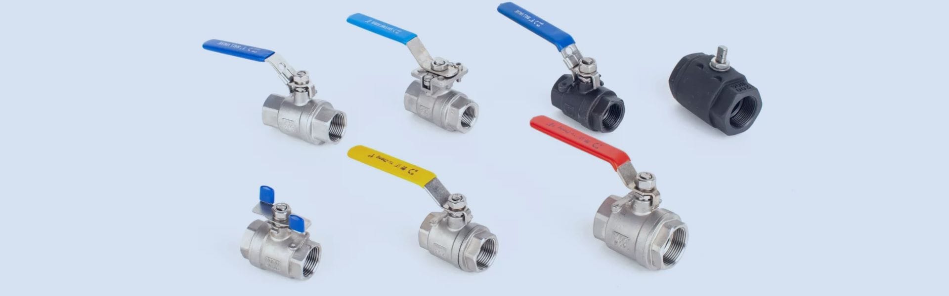
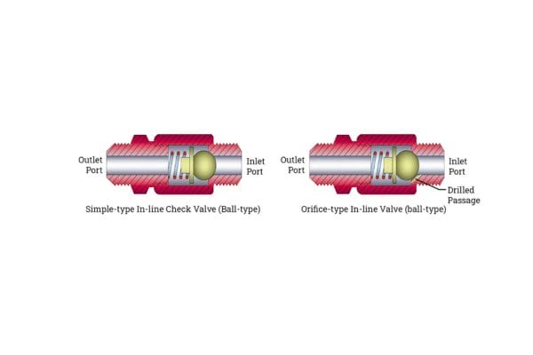
Valves: Valves control the flow and direction of hydraulic fluid within the system. They can regulate pressure, manage flow rates, and direct fluid to different components. Types of valves include check valves, relief valves, and directional control valves.

Hoses: Flexible hoses transport hydraulic fluid between components. They must withstand high pressures and varying temperatures, and their design can significantly affect the system’s performance and noise levels.

Cylinders: Hydraulic cylinders convert hydraulic energy into linear mechanical energy. They consist of a cylinder barrel, piston, and rod, and they facilitate the movement of loads through the controlled application of hydraulic pressure.

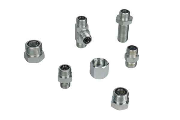
Fittings: These small but critical components connect hoses, tubes, and other elements of the hydraulic system. They ensure leak-free connections and play a significant role in maintaining system integrity and performance.

Together, these components work synergistically to create a functioning hydraulic system capable of performing a wide range of tasks efficiently.

Hydraulic Fluid System

B. Functionality of Hydraulic Fittings

Hydraulic fittings serve as the connectors that link various components within the hydraulic system, ensuring the efficient flow of hydraulic fluid. Their functionality includes:

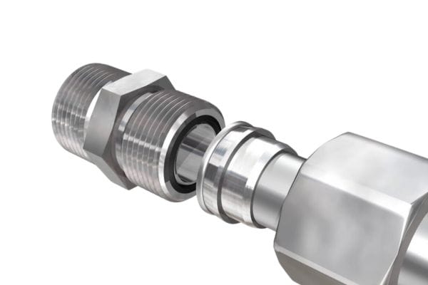
Sealing Connections: Fittings must provide a secure and leak-proof seal to prevent fluid loss and maintain system pressure. This is crucial for both performance and safety, as leaks can lead to system failures and environmental hazards.

Adapting Different Sizes: Fittings often adapt hoses and pipes of different diameters, allowing for flexibility in system design and maintenance. This adaptability is essential in retrofitting existing systems or integrating new components.

Supporting Fluid Dynamics: The design and orientation of fittings can influence fluid flow patterns. Sharp bends or poorly designed fittings can create turbulence, leading to increased noise and energy loss within the system. Therefore, selecting the right fittings is vital for optimizing performance and reducing noise.

Hydraulic fittings not only facilitate connections but also play a significant role in ensuring the overall efficiency and reliability of hydraulic systems.

C. Overview of Noise Generation in Hydraulics

Noise generation in hydraulic systems is a multifaceted issue that can arise from various sources. Understanding these sources is essential for effectively managing and mitigating noise. Key factors contributing to noise generation include:

Fluid Dynamics: As fluid flows through pumps, valves, and fittings, changes in velocity and direction can create turbulence. This turbulence leads to pressure fluctuations, which manifest as audible noise.

Mechanical Operations: The operation of pumps and other components generates mechanical noise. For instance, cavitation—occurring when vapor bubbles form and collapse within a pump—can produce loud, damaging sounds that affect system performance.

Resonance and Vibration: Each component of a hydraulic system has a natural frequency. When operational frequencies approach these natural frequencies, resonance can occur, amplifying vibrations and resulting in increased noise levels. Components such as steel tubes and hoses are particularly susceptible to vibration transmission.

External Influences: Environmental factors, such as nearby machinery or background noise, can exacerbate the perception of hydraulic noise. Additionally, poor installation or maintenance practices can increase noise levels due to misalignment or wear.

Causes of Noise in Hydraulic Fitting Systems

A. Mechanical Sources of Noise

Pump Operations

Pumps are integral to hydraulic systems, and their operations can be significant sources of noise. Several phenomena contribute to this:

Cavitation: This occurs when the pressure in the pump drops below the vapor pressure of the fluid, leading to the formation of vapor bubbles. When these bubbles collapse, they create shock waves that produce loud, damaging noises. Cavitation not only generates noise but also causes severe wear on pump components, reducing their lifespan and efficiency.

Turbulence: As hydraulic fluid is forced through the pump, changes in flow velocity can create turbulence. This chaotic fluid motion generates sound waves, contributing to the overall noise in the system. Turbulent flow can also increase energy losses, making the system less efficient.

Vibration: Pumps inherently generate vibrations during operation due to moving parts. If not properly mounted or isolated, these vibrations can transmit through the system, amplifying noise levels. Additionally, mechanical imbalances or misalignments can exacerbate this issue, leading to higher levels of vibration and associated noise.

Fluid Pulsations

Fluid pulsations are another critical contributor to noise in hydraulic systems. These pulsations can arise from various sources, including:

Pressure Variations: When fluid is pumped, pressure changes can create fluctuations in flow rates. These variations lead to pulsating flow, which generates sound waves as the fluid moves through the system. The frequency and intensity of these pulsations can vary based on the pump type and operating conditions.

Impact on Components: Pulsating fluid can cause vibrations in hoses, fittings, and valves, leading to additional noise. This impact can create a feedback loop, where increased noise results in greater component wear, further enhancing noise production.

Understanding the dynamics of fluid pulsations is essential for noise management, as they can significantly influence the overall acoustic environment of hydraulic systems.

B. Turbulence and Flow Changes

Hydraulic fittings play a crucial role in managing fluid flow within the system. Their design and placement can significantly affect noise generation through turbulence and flow changes:

Flow Velocity Changes: As fluid passes through fittings, any abrupt changes in diameter or direction can cause increased turbulence. This turbulence not only generates noise but can also lead to pressure drops and energy losses, negatively impacting system efficiency.

Types of Fittings: Different types of fittings, such as elbows, tees, and adapters, have varying impacts on flow dynamics. Sharp bends or poorly designed fittings can create areas of low pressure, further exacerbating turbulence and noise levels. Optimizing fitting design and placement is critical for minimizing noise.

Effect of Hose Length and Routing: The length and routing of hoses connecting fittings can also influence noise. Longer hoses may lead to increased fluid friction, while improper routing can cause bends and kinks that disrupt smooth fluid flow, generating noise.

By addressing turbulence and optimizing flow changes, hydraulic system designers can significantly reduce noise levels, leading to improved overall performance.

Hydraulic Fitting System Noise

C. External Factors

Several external factors can exacerbate noise levels in hydraulic systems, impacting both performance and operator comfort:

Environmental Noise: Hydraulic systems are often installed in noisy environments, where external sounds can compound the noise generated internally. This background noise can make it challenging to identify and address specific issues within the hydraulic system, leading to a more significant overall noise burden.

Operator-Induced Factors: The actions of operators can influence noise levels as well. For instance, improper operation, such as rapidly changing flow rates or aggressive control of valves, can lead to increased turbulence and noise. Training operators on best practices can help mitigate these issues.

System Layout: The physical layout of the hydraulic system can also impact noise transmission. Systems with inadequate support or those poorly mounted can vibrate excessively, leading to increased noise levels. Moreover, proximity to other machinery can result in noise amplification and transmission, further complicating noise management.

Implications of Hydraulic System Noise

A. Impact on System Efficiency

Noise in hydraulic systems often correlates with energy losses. When pumps, fittings, or hoses produce excessive noise, it usually indicates inefficiencies such as turbulence, fluid resistance, or pressure drops, which consume additional energy. For instance, turbulence and fluid pulsations caused by improperly chosen fittings can result in pressure loss, requiring more power to achieve the desired output. This increased energy demand not only raises operational costs but also reduces the overall efficiency of the system, leading to a higher total cost of ownership over time. Recognizing and addressing these sources of noise can improve system performance and energy efficiency.

B. Effects on Component Longevity

Noise is often a sign of mechanical stress within the hydraulic system. Persistent vibrations and pressure fluctuations place additional strain on components like pumps, valves, and fittings, accelerating wear and leading to premature failure. For example, cavitation within pumps—a common noise source—can severely damage internal components, reducing their lifespan and requiring frequent replacements. Similarly, fittings subjected to high vibrations and fluid pulsations may experience fatigue, leading to cracks or leaks. Over time, addressing noise issues can enhance the durability of components, thereby extending the system’s operational lifespan and reducing maintenance costs.

C. Operator Health and Safety

High noise levels pose significant health risks to operators, including noise-induced hearing loss (NIHL) and fatigue. Prolonged exposure to noise above 85 decibels can result in permanent hearing damage, with hydraulic systems often reaching or exceeding this threshold. Noise can also contribute to physical and mental fatigue, reducing operators’ ability to concentrate, which may lead to errors or accidents. By managing noise levels, companies can create a safer, more comfortable work environment, ultimately promoting worker health and reducing the likelihood of occupational hazards associated with prolonged exposure to loud hydraulic systems.

Strategies for Noise Reduction

A. Design Considerations

Effective noise reduction in hydraulic systems begins with thoughtful design. Incorporating noise mitigation strategies from the outset can lead to significant long-term benefits. Key design considerations include:

Component Placement: Positioning pumps, valves, and other components strategically can minimize the transmission of noise throughout the system. For example, isolating pumps from the main structure using vibration-dampening mounts can help reduce noise levels significantly.

Fluid Path Design: A well-planned fluid path with smooth transitions and minimal bends can reduce turbulence and pressure drops. Designing fluid circuits with gradual changes in diameter or using sweeping bends instead of sharp elbows can help maintain laminar flow, thereby reducing noise generation.

Material Selection: Using materials that absorb sound rather than transmit it can effectively mitigate noise. For instance, composite materials or rubber can dampen vibrations compared to traditional metal components.

By prioritizing noise reduction in the design phase, engineers can create hydraulic systems that operate quietly and efficiently, reducing the need for retroactive modifications.

B. Use of Attenuators and Dampers

Attenuators and dampers are specialized devices designed to minimize noise in hydraulic systems. Their effective implementation can lead to substantial noise reduction:

Attenuators: These devices are specifically designed to reduce the amplitude of sound waves. They work by absorbing and dissipating sound energy, making them particularly useful in areas with high noise generation, such as near pumps and valves. Attenuators can be tuned to specific frequencies, effectively canceling out unwanted noise while allowing desired sounds to pass through.

Dampers: Dampers are installed to absorb vibrations and prevent them from propagating through the hydraulic system. They can be applied to hoses, fittings, and even mounting points of pumps and motors. By using dampers, the energy from vibrations can be absorbed before it leads to increased noise levels, enhancing overall system performance and operator comfort.

Both attenuators and dampers require careful selection based on the specific noise characteristics of the hydraulic system. Properly integrating these devices can lead to a quieter working environment and improved operational efficiency.

C. Selecting the Right Fittings and Hoses

The choice of hydraulic fittings and hoses plays a critical role in managing noise in hydraulic systems. Specific recommendations include:

Smooth Bore Hoses: Selecting hoses with a smooth interior surface can significantly reduce turbulence and fluid pulsations. Hoses designed for high flow rates can help minimize pressure drops and associated noise generation.

Fiber-Reinforced Hoses: These hoses offer flexibility while maintaining high strength, which helps reduce noise generated from vibration. Their design allows for a degree of volumetric expansion, acting similarly to an accumulator, which can dampen pressure fluctuations.

Proper Fitting Design: Choosing fittings that provide gradual transitions and minimize sharp angles can reduce turbulence and subsequent noise. Look for fittings designed specifically for low-noise applications, as these often incorporate features that promote smooth fluid flow.

Regular Maintenance: Regularly inspecting and maintaining fittings and hoses ensures they remain in optimal condition, preventing wear that can lead to increased noise levels. Tightening connections and replacing worn components can help maintain system integrity and reduce noise.

Conclusion

We encourage you to take a proactive approach in evaluating their hydraulic systems for noise issues. Assess the current noise levels and identify potential sources, implementing effective strategies for reduction. Consider investing in the right fittings, hoses, and vibration-dampening technologies, and emphasize design practices that prioritize noise mitigation.


FAQ

What causes noise in hydraulic systems?

Noise in hydraulic systems is primarily caused by mechanical operations of pumps, fluid pulsations, turbulence from fittings, and external factors like environmental noise.

Why is it important to reduce noise in hydraulic systems?

Reducing noise is crucial for improving system efficiency, extending component lifespan, ensuring operator safety, and complying with regulatory standards.

What are some common strategies for noise reduction?

Strategies include optimizing system design, using attenuators and dampers, selecting smooth bore and fiber-reinforced hoses, and choosing fittings that minimize turbulence.

How can high noise levels affect operators?

Prolonged exposure to high noise levels can lead to noise-induced hearing loss, fatigue, reduced concentration, and increased risk of accidents.

What are the regulatory noise limits for workplaces?

OSHA guidelines state that noise exposure should not exceed 85 dB(A) over an eight-hour workday to prevent hearing damage.

How can I evaluate my hydraulic system for noise issues?

Conduct regular inspections to measure noise levels, identify sources of noise, and assess the condition of components like pumps, hoses, and fittings.

Hard Seat and Soft Seat Check Valves banner

Hard Seat and Soft Seat Check Valves: How to Make a Choice

Check valves are essential components in fluid systems, designed to allow fluid flow in one direction while preventing backflow. This crucial function helps maintain system pressure, protect equipment from damage, and ensure the efficient operation of hydraulic and pneumatic systems.

Understanding Check Valves

A. Function of Check Valves in Hydraulic Systems

Check valves play a critical role in hydraulic systems by ensuring fluid flows in a single direction, thereby preventing backflow. This function is essential for maintaining system pressure and protecting components from damage that could result from reverse flow. By allowing fluids to move only in the intended direction, check valves help to optimize system efficiency and reliability. They are significant in applications where fluid backflow can lead to contamination, equipment failure, or operational hazards.

B. Key Components of Check Valves

Check valves consist of several key components that work together to perform their function:

Body: The main structure of the valve, houses the internal components and provides the pathways for fluid flow.

Poppet: A movable element that opens and closes in response to fluid pressure. It allows flow through the valve when pressure is applied in the forward direction and closes to prevent backflow.

Spring: In spring-loaded check valves, the spring assists in closing the poppet when there is no flow or when back pressure occurs. The tension of the spring can affect the crack pressure, which is the minimum pressure required to open the valve.

Seals: Depending on the valve type, seals may be hard (metal) or soft (elastomeric), providing a tight closure to prevent leakage when the valve is closed.

These components work together to ensure the check valve operates effectively, balancing the need for flow with the need to prevent backflow.

C. Applications of Check Valves Across Various Industries

Check valves are utilized in a wide range of applications across multiple industries, including:

Oil and Gas: Used in pipelines and processing facilities to prevent backflow and protect equipment from high-pressure surges.

Water Treatment: Essential in water distribution systems to maintain pressure and prevent contamination from backflow.

Manufacturing: Employed in hydraulic systems for machinery, ensuring smooth operation and protecting sensitive components.

Food and Beverage: Used to maintain hygiene standards by preventing backflow in processing lines and ensuring safe fluid movement.

HVAC Systems: Check valves help manage fluid flow in heating and cooling systems, contributing to energy efficiency and system reliability.

Hard Seat Check Valves  

A. Definition and Design

Hard seat check valves are engineered with a metal-to-metal sealing surface, typically made from materials such as stainless steel, brass, or other durable metals. This design ensures a robust connection that can withstand harsh conditions, making them ideal for a variety of industrial applications. The sealing mechanism relies on the contact between the valve’s poppet and the valve seat, which is often machined to precise tolerances to minimize leakage when the valve is closed.

In a hard seat check valve, the poppet is spring-loaded, allowing it to remain closed when no forward flow is present. When fluid flows in the intended direction and reaches a specified pressure, the poppet opens, permitting fluid to pass through. Upon cessation of flow or when back pressure is detected, the spring force closes the poppet tightly against the seat, effectively blocking any reverse flow.

Hard Seat Check Valves

B. Advantages of Hard Seat Check Valves

Durability and Wear Resistance:

Hard seat check valves are renowned for their durability. The metal-to-metal seal can withstand abrasive and corrosive environments, making these valves suitable for applications involving harsh fluids or extreme conditions. Their resilience against wear and tear translates to a longer operational lifespan, reducing the frequency of replacements.

Suitable for High-Pressure Applications:

These valves excel in high-pressure scenarios, where maintaining structural integrity is paramount. Hard seat check valves can handle significant pressure differentials without compromising performance. This capability makes them ideal for industries such as oil and gas, where pressures can exceed standard operating limits. Their robust design allows for reliable operation in demanding environments.

C. Disadvantages of Hard Seat Check Valves

Potential for Leakage in Low-Pressure Scenarios:

One of the main drawbacks of hard seat check valves is their potential for leakage at low pressures. The metal seal may not create an adequate barrier when fluid pressures are insufficient to keep the poppet firmly seated against the valve body. This characteristic can lead to fluid bypassing the valve, especially in systems that experience varying pressure conditions.

Higher Maintenance Needs:

While hard seat check valves are durable, they can require more maintenance compared to soft seat valves. Over time, wear on the metal seat can lead to decreased sealing effectiveness, necessitating regular inspections and potential refurbishments. Additionally, in applications where fluid contamination is a risk, the valve’s internal components may need frequent cleaning or replacement to maintain optimal performance.

D. Common Applications and Industry Usage

Hard seat check valves are widely utilized in various industries due to their unique advantages:

Oil and Gas: In exploration and production, hard seat check valves are critical for preventing backflow in pipelines and processing facilities. They are often found in high-pressure environments, ensuring safe fluid transport and operational efficiency.

Chemical Processing: These valves are commonly used in chemical plants where corrosive fluids are handled. Their ability to resist wear and contamination makes them suitable for maintaining the integrity of chemical processes.

Water and Wastewater Treatment: Hard seat check valves are employed in municipal water systems to prevent backflow and protect treatment equipment. Their durability ensures reliable operation in environments subject to variable flow and pressure conditions.

Power Generation: In power plants, hard seat check valves are essential for controlling fluid flow in cooling and hydraulic systems. They help maintain system stability and prevent unwanted backflow that could disrupt operations.

Mining and Mineral Processing: These valves are used to manage the flow of slurries and other abrasive materials. Their robust design allows them to handle the challenges presented by such environments effectively.

Soft Seat Check Valves

A. Definition and Design

Soft seat check valves are designed with a sealing mechanism that utilizes elastomeric or polymeric materials for the seat. Unlike hard seat check valves, which rely on metal-to-metal contact, soft seat valves feature seals made from materials such as rubber, nitrile, or other soft compounds. This design allows for a flexible and compressible interface between the valve’s poppet and seat, which enhances the sealing effectiveness.

The operation of a soft seat check valve is similar to that of a hard seat valve. The poppet opens under forward flow conditions, allowing fluid to pass through, and closes when back pressure is detected. The elastomeric seal compresses against the seat, creating a tight barrier that effectively prevents backflow. This design is particularly beneficial in applications where leakage prevention is critical.

Soft Seat Check Valves

B. Advantages of Soft Seat Check Valves

Enhanced Sealing Capabilities:

One of the primary advantages of soft seat check valves is their superior sealing performance. The elastomeric material conforms to the mating surfaces, creating a tighter seal than metal surfaces can achieve. This characteristic minimizes leakage, even under varying pressure conditions, making soft seat valves ideal for applications where backflow must be strictly prevented.

Better Performance in Cleanliness-Sensitive Applications:

Soft seat check valves are particularly well-suited for industries that require high levels of cleanliness, such as food and beverage processing, pharmaceuticals, and semiconductor manufacturing. The smooth surfaces of the elastomeric seals reduce the risk of fluid contamination, ensuring that the integrity of the fluid remains intact. Additionally, soft seat valves can be designed for easy cleaning and sanitization, further enhancing their suitability for hygienic applications.

C. Disadvantages of Soft Seat Check Valves

Limited Temperature and Pressure Ranges:

Soft seat check valves typically have more stringent operational limits regarding temperature and pressure compared to hard seat valves. The elastomeric materials used in their construction may degrade or lose their sealing properties when exposed to high temperatures or extreme pressures. Users must carefully evaluate the operational parameters of their applications to ensure that the selected soft seat valve is capable of performing reliably within those limits.

Vulnerability to Fluid Contamination:

While soft seat valves excel in cleanliness-sensitive environments, they are also susceptible to damage from certain fluids. For instance, aggressive chemicals or abrasive materials can degrade the elastomeric seals over time. This vulnerability necessitates a thorough assessment of the fluids being handled to prevent premature valve failure and ensure long-term operational reliability.

D. Common Applications and Industry Usage

Soft seat check valves find extensive use across various industries due to their unique advantages:

Food and Beverage: In processing and bottling applications, soft seat check valves are essential for maintaining hygiene and preventing contamination. Their enhanced sealing capabilities ensure that the quality of the product remains uncompromised.

Pharmaceuticals: Soft seat valves are commonly used in pharmaceutical manufacturing, where sterile conditions are paramount. They help maintain the integrity of sensitive compounds while preventing backflow that could introduce contaminants.

Water Treatment: In municipal water systems, soft seat check valves are employed to prevent backflow in systems handling treated water. Their effective sealing characteristics help maintain the quality of potable water.

HVAC Systems: Soft seat check valves are used in heating, ventilation, and air conditioning systems to manage fluid flow and maintain system efficiency. Their ability to prevent backflow contributes to improved energy efficiency.

Key Factors for Selection

A. Assessing Operational Requirements

Pressure and Temperature Conditions:

When selecting check valves, it’s crucial to assess the specific pressure and temperature conditions of the application. Each type of check valve, whether hard seat or soft seat, has defined operational limits that must be adhered to for optimal performance. Hard seat check valves are generally suitable for high-pressure environments, while soft seat valves are better for moderate-pressure applications. Understanding the maximum and minimum pressures and temperatures the valve will encounter ensures that the chosen valve can maintain its integrity and functionality under operational stress.

Fluid Characteristics (Viscosity, Corrosiveness):

The characteristics of the fluid being handled significantly influence valve selection. Viscosity impacts flow rates and the pressure drops across the valve, which can affect performance and sealing capabilities. For instance, highly viscous fluids may require valves with larger openings or specific design features to facilitate adequate flow. Additionally, the corrosiveness of the fluid should be evaluated, as it affects material compatibility. Soft seat valves may not withstand aggressive chemicals, whereas hard seat valves might be more appropriate in such environments. Consulting fluid compatibility charts and considering the specific properties of the fluids involved is essential in making informed selections.

Applications Ball Valve

B. Evaluating Application Needs

Importance of Leakage Prevention:

In many applications, preventing leakage is a critical factor. Soft seat check valves excel in this regard due to their enhanced sealing capabilities, making them suitable for applications where even minimal leakage could lead to significant issues, such as contamination or loss of product quality. Conversely, if the application involves high pressures and the risk of leakage is less critical, hard seat valves may be the preferred option. Understanding the consequences of potential leakage in the specific application helps guide the selection process.

Frequency of Operation and Maintenance Considerations:

The operational frequency of the valve also plays a role in the selection process. For systems that require frequent cycling, the chosen valve should be capable of withstanding the wear associated with high cycle rates. Soft seat check valves may be preferable in applications that demand cleanliness and minimal leakage, but they may require more frequent inspections and replacements due to wear. In contrast, hard seat valves might be more durable but may necessitate more maintenance if they become worn over time. Evaluating the maintenance requirements alongside the operational demands ensures that the selected valve aligns with the overall system needs.

C. Comparing Lifecycle Costs and Maintenance Requirements

When selecting check valves, it’s vital to consider not just the initial purchase cost but the total lifecycle costs associated with each valve type.

Lifecycle Costs:

Lifecycle costs encompass the initial purchase price, installation expenses, operational costs, and maintenance or replacement costs over time. While hard seat check valves may have a higher upfront cost, their durability can result in lower maintenance expenses and a longer lifespan, making them cost-effective in the long run. Conversely, while soft seat check valves might be less expensive initially, their potential need for more frequent replacements and repairs could lead to higher overall costs.

Maintenance Requirements:

Different valve types come with varying maintenance needs. Hard seat valves might require regular inspections to ensure the integrity of the metal seat, while soft seat valves might need more frequent checks due to wear on the elastomeric seals. Understanding the maintenance protocols, potential downtimes for repairs, and the costs associated with maintaining each valve type is essential for making a financially sound decision.

Practical Considerations  

A. Installation Guidelines for Both Valve Types

Proper installation is crucial for ensuring the effective operation of both hard seat and soft seat check valves. Here are key guidelines for each type:

Hard Seat Check Valves:

Orientation: Ensure that the valve is installed in the correct orientation, as indicated by flow direction arrows on the valve body. This ensures that the valve opens and closes appropriately with the intended flow.

Alignment: Maintain proper alignment with piping to prevent undue stress on the valve body, which can lead to leaks or failure.

Support: Provide adequate support for the valve and piping to reduce vibrations and mechanical stress.

Soft Seat Check Valves:

Avoid over-tightening: When installing soft seat valves, avoid over-tightening the connections, as excessive pressure can damage the elastomeric seal.

Debris Inspection: Before installation, inspect the valve and the connecting pipes for any debris or contaminants that could compromise sealing.

Temperature Considerations: Ensure that the installation environment does not exceed the temperature limits of the elastomeric material.

B. Maintenance Practices for Longevity

Routine maintenance is essential for both types of check valves to ensure longevity and reliable performance:

Hard Seat Check Valves:

Regular Inspections: Conduct regular visual inspections to identify any signs of leakage or corrosion around the valve body and connections.

Cleaning: Keep the valve clean and free from debris that could interfere with operation. Periodic cleaning may be necessary, especially in harsh environments.

Soft Seat Check Valves:

Seal Inspection: Regularly inspect the elastomeric seals for signs of wear, cracking, or degradation, as these can lead to leakage.

System Checks: Monitor the fluid flow and pressure to identify any changes that could indicate valve performance issues. Address any abnormalities promptly.

C. Signs of Wear or Failure to Watch For in Each Valve Type

Identifying signs of wear or failure early can prevent larger issues in the system:

Hard Seat Check Valves:

Leakage: Noticeable leakage around the valve body is a primary indicator of wear or failure. If leakage occurs even under normal operational pressures, the valve may need replacement.

Difficulty in Operation: If the valve becomes increasingly difficult to open or close, it may indicate internal wear or misalignment.

Soft Seat Check Valves:

Fluid Contamination: Any signs of contamination in the fluid could suggest that the elastomeric seal is compromised and fails to provide an adequate seal.

Inconsistent Performance: Fluctuations in flow rates or pressure drops may indicate seal degradation, leading to backflow issues.

Conclusion

As you consider your options for check valves, we encourage further research into the nuances of both hard seat and soft seat designs. Professional consultation can provide invaluable guidance, helping you navigate the complexities of valve selection and ensuring that your choices align with best practices in fluid management.


FAQ

What is the main difference between hard seat and soft seat check valves?

Hard seat check valves use metal-to-metal sealing, making them durable and suitable for high-pressure applications. Soft seat check valves feature elastomeric seals that provide better sealing performance and are ideal for cleanliness-sensitive environments.

When should I choose a hard seat check valve?

Opt for a hard seat check valve when your application requires high pressure, durability, and resistance to wear. They are also preferred in environments where fluid contamination is a concern.

What are the advantages of soft seat check valves?

Soft seat check valves offer enhanced sealing capabilities, minimizing leakage and providing better performance in systems requiring high cleanliness levels. They are often used in applications involving sensitive fluids.

How do I know which type of check valve to select for my application?

Assess factors such as pressure and temperature conditions, fluid characteristics, and the importance of leakage prevention. Evaluating these criteria will guide you in choosing the most suitable valve type.

What maintenance practices should I follow for check valves?

Regular inspections for leaks, cleaning to remove debris, and monitoring for signs of wear are essential maintenance practices. For soft seat valves, check seals frequently for degradation.

Are there any signs that indicate a check valve needs replacement?

Yes, signs include noticeable leakage around the valve, difficulty in operation, fluid contamination, and inconsistent flow rates. Addressing these issues promptly can prevent further complications in your system.

Common Mistakes to Avoid in O-Ring Face Seal Assembly banner

Common Mistakes to Avoid in O-Ring Face Seal Assembly

O-ring face seal fittings play a crucial role in hydraulic systems by providing leak-free connections essential for efficient operation. These fittings utilize a captive O-ring situated in a specially designed groove, known as the Captive O-ring groove (CORG). When properly assembled, the O-ring is compressed against a flat face, creating a tight seal that withstands high pressures and prevents fluid leakage.

Understanding O-Ring Face Seal Fittings

A. Definition and Function

O-ring face seal fittings are specialized connectors used in hydraulic systems to create leak-free joints. They consist of a flat face that interfaces with a matching flat surface, with a captive O-ring situated in a precision-machined groove known as the Captive O-ring groove (CORG). When the fitting is assembled, the O-ring is compressed between the two surfaces, forming a tight seal that prevents fluid leakage. This design allows for high-pressure operation, making these fittings suitable for demanding hydraulic applications where reliability and safety are paramount.

B. Components of O-Ring Face Seal Assemblies

Understanding the key components of O-ring face seal assemblies is essential for effective assembly and maintenance.

O-Ring

The O-ring is a circular elastomeric sealing component that provides the primary sealing function in the assembly. Made from various materials—such as rubber, neoprene, or fluorocarbon—the choice of O-ring material depends on factors like temperature, pressure, and the type of fluid being sealed. Proper selection and installation of the O-ring are critical, as they directly influence the sealing performance and longevity of the connection.

Captive O-Ring Groove (CORG)

The CORG is a specially designed groove within the fitting body that holds the O-ring in place during assembly. Its design ensures that the O-ring remains correctly positioned and protected from damage during handling and installation. The CORG’s geometry is crucial for achieving uniform compression of the O-ring, facilitating a reliable seal when the fitting is tightened. Understanding the CORG’s design helps ensure that the O-ring is installed correctly and functions as intended.

Fitting Body and Connection Surfaces

The fitting body is the main component that houses the O-ring and connects to other system components. The flat faces of the fitting body and the corresponding connection surface must be clean and free of defects to ensure a proper seal. Any burrs, scratches, or contaminants can compromise the seal, leading to leaks. Regular inspection and maintenance of these surfaces are necessary to sustain optimal performance in hydraulic applications.

ORFS Fitting Types

C. Applications and Benefits of O-Ring Face Seal Fittings

O-ring face seal fittings are widely used across various industries, including aerospace, automotive, manufacturing, and construction. Their applications include hydraulic lines, pneumatic systems, and fluid transfer systems. The benefits of using O-ring face seal fittings include:

Leak Prevention: The design allows for a robust seal that effectively prevents fluid leaks, enhancing system reliability.

High-Pressure Capability: These fittings can withstand high-pressure conditions, making them suitable for demanding environments.

Ease of Assembly: The straightforward assembly process, when done correctly, simplifies installation and maintenance.

Versatility: O-ring face seal fittings can accommodate a range of fluid types and operational conditions, making them adaptable to various applications.

Common Mistakes in O-Ring Face Seal Assembly  

Proper assembly of O-ring face seal fittings is crucial to ensure leak-free connections in hydraulic systems. However, various common mistakes can compromise the integrity of these assemblies. Understanding these pitfalls and their implications is essential for achieving optimal performance.

A. Ignoring O-Ring Inspection

Importance of Checking for Proper O-Ring Installation

Before assembly, it is vital to inspect the O-ring to ensure it is correctly installed in the captive O-ring groove (CORG). A properly seated O-ring is essential for forming an effective seal. Failing to check for the correct installation can lead to incomplete sealing, causing fluid leaks and system failures. Regular training and awareness about O-ring inspection can significantly reduce this risk.

Consequences of Missing or Damaged O-Rings

If an O-ring is missing or damaged, the assembly will not function as intended. Common consequences include fluid leakage, which can lead to equipment malfunction, increased maintenance costs, and potential safety hazards. In severe cases, leaks can result in environmental contamination or catastrophic system failures, highlighting the importance of thorough inspection.

B. Inadequate Surface Preparation

Cleaning and Inspecting Connection Surfaces

Proper surface preparation is crucial for achieving a reliable seal. Connection surfaces must be free of debris, oil, and contaminants. Failing to clean these surfaces can hinder the O-ring’s ability to form a tight seal, leading to leaks. Technicians should adopt a consistent cleaning protocol, using appropriate cleaning agents to ensure all surfaces are adequately prepared.

Common Contaminants That Can Affect Seals

Contaminants such as dirt, dust, moisture, and oil can significantly affect the sealing performance. Even small particles can prevent the O-ring from making full contact with the fitting surfaces. Regular inspections and cleaning routines should be implemented to minimize the risk of contamination, ensuring that surfaces are pristine before assembly.

C. Improper Mating of Fitting Faces

Importance of Complete Contact with the O-Ring

For an O-ring face seal to function correctly, the flat faces of the fitting must make complete contact with the O-ring. Inadequate mating can create gaps that allow fluid to escape, undermining the integrity of the connection. Technicians should ensure that both the fitting and connection surfaces are aligned correctly to achieve optimal contact with the O-ring.

Risks of Misalignment or Inadequate Mating

Misalignment during assembly can lead to uneven pressure distribution across the O-ring, causing premature wear or failure. If the fitting faces are not mated properly, it can result in leaks and necessitate reassembly, leading to increased downtime and costs. Using visual aids or alignment tools can help technicians ensure proper mating during assembly.

ORFS Hydraulic Fittings Leaking Topa

D. Incorrect Torque Application

Importance of Following Manufacturer Torque Specifications

Each fitting type comes with specific torque specifications provided by the manufacturer. Adhering to these guidelines is crucial to ensure that the O-ring is compressed adequately without being over-tightened. Neglecting these specifications can result in ineffective sealing and increase the risk of leaks.

Risks of Over-Tightening and Under-Tightening

Over-tightening can damage the fitting, crush the O-ring, or lead to cold working of the material, which may compromise future assemblies. Conversely, under-tightening can create gaps, allowing fluid to leak. Both scenarios highlight the need for precise torque application to ensure reliable assembly.

E. Neglecting Post-Assembly Inspection

Signs of Poor Assembly to Look For

After assembly, it is essential to conduct a thorough inspection to identify any signs of poor assembly. Indicators such as visible O-rings, misaligned fittings, or excessive gaps between sealing surfaces should prompt a re-evaluation of the assembly process. Recognizing these signs early can prevent leaks and equipment failures.

Importance of Visual Checks for Leaks

Conducting visual inspections for leaks after assembly is critical. Technicians should look for signs of fluid seeping from the connection points and verify that the assembly is seated correctly. Implementing a standard post-assembly inspection checklist can help ensure that all connections are secure and functioning as intended.

Best Practices for O-Ring Face Seal Assembly

A. Pre-Assembly Preparation

Tools and Materials Needed

Before starting the assembly process, it is crucial to have all the necessary tools and materials on hand. This preparation not only enhances efficiency but also reduces the risk of overlooking critical components that can compromise the assembly. Essential items include:

O-ring face seal fittings: Ensure you have the correct size and type for your application.

Captive O-rings (CORG): These must be compatible with the fittings and suitable for the operating conditions.

Torque wrench: A calibrated tool is vital for applying the correct torque to the fittings.

Cleaning agents and cloths: Use appropriate solvents or cleaners to ensure surfaces are contaminant-free.

Lubricants compatible with O-ring materials: Select lubricants that are safe for the O-ring material to avoid degradation.

Inspection tools (magnifying glass, calipers): These tools help verify the condition and dimensions of O-rings and fittings.

Having these tools ready can streamline the assembly process and ensure that no critical steps are overlooked, ultimately leading to a more reliable assembly.

Steps for Thorough Inspection and Cleaning

Effective pre-assembly preparation involves careful inspection and cleaning of both the O-ring and connection surfaces to ensure a successful assembly:

Inspect O-Rings: Check for any visible damage or wear. Look for cracks, tears, or deformation that could compromise the seal. Ensure that the O-ring is intact and properly seated in the CORG (captured O-ring groove).

Clean Connection Surfaces: Utilize appropriate cleaning agents to remove contaminants such as dirt, oil, or debris from the fitting and connection surfaces. Ensure the surfaces are dry and free from any residues before proceeding to assembly. Cleaning is crucial because contaminants can create gaps in the seal and lead to leaks.

Verify Dimensions: Measure the O-ring and fitting dimensions to confirm they meet the required specifications. This step helps prevent misalignment and ensures proper sealing. Utilize calipers to check the diameter and width of the O-ring, and compare these measurements with the manufacturer’s specifications.

B. Step-by-Step Assembly Instructions

Proper Sequence of Assembly Steps

Following a specific sequence during assembly is crucial for achieving a successful O-ring face seal:

Prepare the O-Ring: Lightly lubricate the O-ring with a compatible lubricant to facilitate smooth installation. Be cautious not to over-lubricate, as excess lubricant can attract contaminants and affect the sealing performance.

Mate the Fitting Faces: Align the flat face of the fitting with the connection surface. Ensure the O-ring makes full contact with both surfaces, maintaining even pressure. This step is critical; any misalignment can lead to leaks.

Thread the Nut: Begin threading the nut onto the fitting body by hand, ensuring it moves freely without cross-threading. Avoid applying excessive force during this step, as cross-threading can damage the threads and lead to improper sealing.

Torque Application: Using a calibrated torque wrench, tighten the nut according to the manufacturer’s specifications. Apply torque gradually, ensuring an even distribution of force. This careful application of torque is essential to prevent both over-tightening and under-tightening, both of which can compromise the seal.

Final Checks: After achieving the recommended torque, conduct a visual inspection of the assembly to confirm that the O-ring is not visible and that the fitting is properly seated. Look for any signs of misalignment or gaps that might indicate an improper fit.

Emphasis on the Importance of Each Step

Each step in the assembly process contributes to the overall integrity of the fitting. Proper lubrication reduces wear on the O-ring, while precise torque application ensures a secure connection without damaging components. Following these steps systematically can prevent leaks and enhance the longevity of the assembly, ensuring optimal performance in hydraulic systems.

ORFS Hydraulic Fitting Installation

C. Post-Assembly Verification

Checklist for Ensuring a Successful Assembly

Conducting a thorough post-assembly verification is critical. Utilize a checklist that includes:

Confirmation that the O-ring is properly installed and not visible.

Assurance that the fitting faces are aligned and fully mated.

Verification that the nut is tightened to the correct torque specification.

Inspection of connection surfaces for any signs of misalignment or damage.

Completing this checklist helps identify any issues that may compromise the assembly’s effectiveness. This proactive approach can save time and resources by catching potential problems before the system goes live.

Techniques for Leak Testing

After assembly, it is essential to perform leak testing to ensure the integrity of the connection. Common techniques include:

Visual Inspection: Look for any signs of fluid leakage at the connection points under normal operating conditions. This quick assessment can help identify obvious leaks.

Pressure Testing: Apply pressure to the system and monitor for any pressure drops, which may indicate a leak. This method is effective for identifying leaks in high-pressure systems.

Dye Testing: Introduce a dye into the system and observe for any signs of leakage. The dye makes it easier to detect small leaks that might otherwise go unnoticed.

Conclusion

To enhance the reliability of O-ring face seal assemblies, it is crucial to adopt best practices consistently. This includes thorough pre-assembly preparations, following a detailed step-by-step assembly process, and conducting comprehensive post-assembly verifications. By ensuring that each step is performed with care and precision, technicians can significantly reduce the risk of leaks and improve the overall performance of hydraulic systems.


FAQ

What is an O-ring face seal fitting?

An O-ring face seal fitting is a type of hydraulic fitting that uses a captive O-ring to create a leak-tight seal at the interface between the fitting and the connected component.

Why is proper assembly important for O-ring face seal fittings?

Proper assembly is crucial to ensure a reliable, leak-free connection. Mistakes during assembly can lead to leaks, system failures, and costly downtime.

What should I inspect before assembling O-ring face seal fittings?

Inspect the O-ring for any damage or wear, clean the connection surfaces to remove contaminants, and verify the dimensions of the O-ring and fittings.

What is the correct torque for tightening O-ring face seal fittings?

The correct torque specifications can vary by manufacturer. Always refer to the manufacturer’s guidelines for the specific fittings being used.

How can I test for leaks after assembly?

Common leak testing methods include visual inspections, pressure testing, and dye testing to identify any fluid leaks at the connection points.

What common mistakes should I avoid during assembly?

Avoid ignoring O-ring inspection, inadequate surface preparation, improper mating of fitting faces, incorrect torque application, and neglecting post-assembly inspections.

Check Valve Selection banner

Check Valve Selection: Understanding Flow Characteristics

Check valves play a crucial role in hydraulic systems, ensuring the smooth and efficient operation of various applications across multiple industries. These devices prevent the backflow of fluids, safeguard equipment, and maintain system pressure. Without check valves, hydraulic systems could suffer from severe operational issues, including fluid contamination, equipment damage, and reduced efficiency.

What is a Check Valve?

A check valve is a mechanical device designed to allow fluid to flow in one direction while preventing reverse flow. Its primary function is to maintain the integrity of hydraulic systems by ensuring that fluids do not flow backward, which can cause damage to equipment, contamination, and loss of system pressure. This one-way flow mechanism is essential in various applications, from simple plumbing systems to complex industrial machinery.

A. Definition and Function

Check valves, also known as non-return valves or one-way valves, operate based on pressure differentials. When the pressure on the inlet side exceeds the pressure on the outlet side, the valve opens, allowing fluid to pass through. Conversely, when the outlet pressure exceeds the inlet pressure, the valve closes, preventing backflow. This functionality is crucial for maintaining the efficiency and safety of hydraulic circuits.

B. Basic Components of a Check Valve

A typical check valve consists of several key components:

Body: The main structure that houses the internal components and connects to the piping system.

Poppet: A movable element that opens and closes the valve based on fluid pressure. It seals the valve when closed, preventing backflow.

Spring: Often used to assist the poppet in closing the valve. It can help maintain the valve in a closed position until the necessary crack pressure is reached.

Retainer: Holds the internal components in place and ensures proper alignment and functioning.

These components work together to create a reliable mechanism that protects hydraulic systems from potential failures.

check valve types

C. Common Applications Across Industries

Check valves are used in a wide range of applications across various industries, including:

Hydraulic Systems: Ensuring one-way flow in hydraulic circuits, protecting pumps and actuators from backflow.

Water and Wastewater Management: Preventing contamination in water supply systems and managing flow in treatment facilities.

Oil and Gas: Protecting pipelines from pressure surges and ensuring safe operation in drilling and extraction processes.

Manufacturing: Used in various machinery to maintain pressure and prevent fluid leaks in production processes.

Understanding Flow Characteristics

Understanding flow characteristics is essential for selecting the appropriate check valve for any hydraulic application. These characteristics influence how fluids behave within a system and directly impact the performance of check valves. A thorough grasp of flow characteristics ensures that the selected valve can operate effectively under specific conditions, enhancing overall system efficiency.

A. Definition of Flow Characteristics

Flow characteristics refer to the various properties and behaviors of fluids as they move through a hydraulic system. This includes how fluid flows through pipes, valves, and other components, as well as the forces acting on them. Key flow characteristics include flow rate, velocity, pressure, and the nature of the fluid itself (such as its viscosity). By analyzing these characteristics, engineers can predict how fluids will interact with system components, including check valves, and make informed decisions during the selection process.

B. Key Factors Affecting Flow Characteristics

Flow Rate:

Flow rate is the volume of fluid that passes through a specific point in the system over a given time period, typically measured in gallons per minute (GPM) or liters per second (L/s). It is a critical factor in determining the size and type of check valve needed. Higher flow rates may require valves with larger openings or specific designs to minimize pressure drops and ensure that the valve opens and closes appropriately. Understanding the expected flow rate helps in selecting a valve that can handle the system’s demands without causing cavitation or excessive turbulence.

Fluid Viscosity:

Viscosity is a measure of a fluid’s resistance to flow. Fluids with high viscosity, such as oils or sludges, flow more slowly than low-viscosity fluids like water. The viscosity of a fluid affects the flow characteristics significantly, as it influences the force required to move the fluid through pipes and valves. When selecting a check valve, it’s essential to consider the viscosity of the fluid to ensure that the valve can operate effectively without excessive pressure loss or risk of clogging. For example, a check valve in a high-viscosity system may require a larger crack pressure to ensure proper function.

Temperature Variations:

Temperature has a dual impact on fluid behavior and valve performance. As temperature increases, many fluids become less viscous, allowing for easier flow. Conversely, low temperatures can increase viscosity, potentially leading to operational challenges. Additionally, temperature variations can affect the materials used in the construction of check valves. It is crucial to select a valve that can withstand the expected temperature range without degrading or losing functionality. This includes considering material compatibility with the fluid at various temperatures, as certain materials may become brittle or lose structural integrity when exposed to extreme heat or cold.

Check Valve Selection

C. Importance of Understanding These Factors in Selection

Understanding the key factors affecting flow characteristics is vital for several reasons:

Optimal Performance: Selecting the right check valve based on flow characteristics ensures optimal performance and reliability within the hydraulic system. Valves that are appropriately sized and designed for specific flow rates, viscosities, and temperatures will operate more efficiently and reduce the risk of malfunctions.

Cost-Effectiveness: Making informed decisions about valve selection can prevent costly mistakes and reduce downtime due to equipment failures. A well-chosen check valve can enhance system efficiency, potentially lowering operational costs and prolonging the life of other components.

System Safety: Proper understanding of flow characteristics contributes to the safety of hydraulic systems. Check valves that do not meet the specific flow requirements can lead to backflow, pressure surges, or system failures, posing risks to equipment and personnel.

Crack Pressure

Crack pressure is a critical concept in the selection and operation of check valves. It plays a significant role in determining how effectively a valve functions within a hydraulic system. Understanding crack pressure can help engineers and technicians make informed decisions to optimize system performance.

A. Definition of Crack Pressure

Crack pressure refers to the minimum pressure required to open a check valve and allow fluid to flow through it. When the pressure on the inlet side of the valve exceeds this threshold, the valve’s poppet lifts, enabling fluid to pass. Conversely, when the pressure on the outlet side is higher than the inlet pressure, the valve closes to prevent backflow. Crack pressure is a vital parameter, as it directly influences the timing and responsiveness of the check valve within a hydraulic system.

B. How Crack Pressure Affects Flow

The crack pressure of a check valve can significantly impact the flow characteristics of a system:

Flow Regulation: A valve with a low crack pressure will open more easily, allowing fluid to flow quickly, which can be beneficial in systems requiring rapid response times. However, if the crack pressure is set too low, it may lead to unwanted backflow during minor fluctuations in pressure.

Pressure Control: Higher crack pressure can help maintain system pressure by preventing backflow effectively. In applications where pressure stability is crucial, such as in hydraulic systems that require constant pressure to function correctly, selecting a valve with an appropriate crack pressure is essential.

Impact on Efficiency: Incorrectly set crack pressure can lead to inefficient operation. For example, if the crack pressure is too high for a particular application, the valve may not open as intended, restricting flow and causing pressure drops that can impact system performance. Conversely, if it’s too low, it can result in premature valve opening and energy losses.

C. Selecting the Appropriate Crack Pressure for Different Applications

Choosing the right crack pressure involves considering several factors related to the specific application:

System Requirements: Assess the operational parameters of the hydraulic system, including expected flow rates, pressure ranges, and fluid types. Understanding the system’s requirements helps in determining the ideal crack pressure for optimal performance.

Application Environment: Evaluate the environment in which the valve will operate. For instance, systems with significant fluctuations in pressure may require a check valve with a higher crack pressure to prevent unintentional opening.

Fluid Characteristics: The nature of the fluid being used is also critical. More viscous fluids may require different crack pressure settings compared to less viscous fluids due to their flow behavior.

Consultation with Manufacturer Specifications: Manufacturers often provide guidelines and specifications regarding appropriate crack pressure settings for their check valves. Utilizing these resources can help ensure the correct selection for specific applications.

D. Case Studies Showcasing Crack Pressure Impacts

Hydraulic Lift System: In a hydraulic lift system used in automotive service, a check valve with a crack pressure of 10 psi was selected to allow for quick engagement. However, due to frequent backflow during minor pressure fluctuations, a replacement valve with a 15 psi crack pressure significantly improved system stability and reduced maintenance needs.

Chemical Processing Plant: In a chemical processing plant, a low crack pressure valve was initially used, resulting in unwanted backflow and contamination of raw materials. After reassessing the system requirements, engineers switched to a check valve with a crack pressure of 20 psi, which effectively prevented backflow, enhancing both safety and product quality.

Pressure Drop Considerations  

A. Definition of Pressure Drop

Pressure drop refers to the reduction in pressure that occurs as fluid flows through a valve or any other restriction in a hydraulic system. It is a critical measurement, as excessive pressure drop can hinder fluid movement, reduce system efficiency, and lead to potential operational issues. The pressure difference is typically measured in pounds per square inch (psi) or pascals (Pa) and is influenced by various factors, including the design of the valve and the characteristics of the fluid.

B. Factors Influencing Pressure Drop in Check Valves

Several factors contribute to the pressure drop across check valves:

Valve Design: The geometry and construction of the check valve significantly affect pressure drop. Valves with sharp corners, abrupt changes in diameter, or complicated internal designs tend to create higher turbulence and resistance to flow, leading to increased pressure drop.

Flow Rate: Higher flow rates can lead to greater pressure drops due to increased friction and turbulence within the valve. Understanding the expected flow rate is essential for selecting a valve that minimizes pressure loss.

Fluid Viscosity: The viscosity of the fluid influences how easily it flows through the valve. Higher viscosity fluids exhibit greater resistance, resulting in increased pressure drop. Engineers must account for fluid viscosity when selecting check valves to ensure optimal performance.

Temperature: Temperature can impact fluid viscosity and, consequently, the pressure drop. As temperature increases, many fluids become less viscous, potentially reducing pressure drop. Conversely, colder temperatures can increase viscosity, leading to higher pressure losses.

Installation Orientation: The orientation of the valve within the piping system can also affect pressure drop. For instance, check valves installed horizontally may experience different flow characteristics than those installed vertically, impacting the overall pressure drop.

C. Implications of Pressure Drop on System Performance

Excessive pressure drop can have several adverse effects on hydraulic systems:

Reduced Efficiency: A high-pressure drop means that more energy is required to maintain the desired flow rate, leading to inefficiencies. This can result in increased operational costs and strain on pumps and other components.

Inadequate Flow: If the pressure drop is too high, it may prevent the valve from opening fully, restricting flow and potentially causing system malfunctions. This is particularly critical in applications requiring precise flow control.

Increased Wear and Tear: The additional stress on components caused by excessive pressure drop can lead to premature wear and failure, increasing maintenance costs and system downtime.

Operational Safety: In certain applications, such as those involving hazardous fluids, a significant pressure drop can lead to unsafe operating conditions, including leaks or ruptures.

D. Strategies for Minimizing Pressure Drop

To mitigate pressure drop across check valves and enhance system performance, consider the following strategies:

Select the Right Valve Design: Choosing check valves with streamlined designs and minimal flow restrictions can help reduce pressure drop. Valves specifically engineered for low-pressure drop applications should be prioritized.

Optimize Valve Size: Ensure the selected check valve is appropriately sized for the system. Valves that are too small can create unnecessary restrictions, leading to increased pressure drop. Conversely, oversizing can lead to other issues, so a balance must be struck.

Maintain Smooth Piping Systems: Minimize bends, turns, and other obstructions in the piping system that can contribute to turbulence and pressure drop. Using smooth and consistent pipe diameters can improve flow efficiency.

Monitor and Control Flow Rates: Regularly assess flow rates and adjust system parameters to maintain optimal performance. Implementing flow control devices may help manage flow rates more effectively, reducing pressure drop.

Consider Fluid Properties: When selecting valves, account for the viscosity and temperature of the fluid. Ensure that the valve can handle variations in fluid properties, which can help maintain consistent pressure drop.

Orifice Fittings and Their Role

A. Explanation of Orifice Fittings

Orifice fittings are components designed to restrict flow in a hydraulic system by creating a precise opening through which fluid can pass. These fittings are often integrated into check valves or other control devices to manage the flow rate and pressure within a system. The orifice itself is typically a small hole or opening that regulates the volume of fluid allowed to flow through, which can be critical for applications requiring precise control.

Orifice fittings can vary in shape, size, and design, depending on the specific application and fluid characteristics. They are commonly used in hydraulic circuits to limit flow rates, reduce pressure surges, and minimize the risk of fluid cavitation.

B. Importance of Orifice Size and Design

The size and design of the orifice are critical factors that influence how effectively it controls flow:

Orifice Size: The diameter of the orifice determines the maximum flow rate that can pass through. A larger orifice allows for higher flow rates but may lead to increased turbulence and pressure drop. Conversely, a smaller orifice can effectively limit flow but may also restrict it excessively, leading to operational inefficiencies. Thus, selecting the right orifice size is essential for balancing flow control and system performance.

Orifice Shape: The design of the orifice, including its shape and smoothness, impacts flow characteristics. For example, a tapered orifice may facilitate a smoother flow transition compared to a straight-edged orifice, thereby reducing turbulence and enhancing efficiency.

Material Considerations: The materials used for orifice fittings must be compatible with the fluids being handled, as this can affect the longevity and reliability of the fitting. Corrosion-resistant materials may be necessary for aggressive fluids, while softer materials may be suitable for less corrosive applications.

C. Impact on Flow Control and System Efficiency

Orifice fittings are crucial for effective flow control and overall system efficiency in several ways:

Flow Rate Regulation: By restricting flow, orifice fittings allow for precise regulation of fluid movement within the system. This is particularly important in applications where maintaining specific flow rates is critical for performance and safety.

Pressure Management: Orifice fittings help manage pressure levels within hydraulic systems by controlling the amount of fluid passing through. This can prevent pressure surges that may lead to equipment damage or system failures.

Cavitation Prevention: By carefully managing flow rates and pressure, orifice fittings can reduce the risk of cavitation—a phenomenon that occurs when vapor bubbles form in a fluid due to low pressure. Cavitation can lead to significant damage in hydraulic systems, making the role of orifice fittings essential in preventing this issue.

Energy Efficiency: Properly sized and designed orifice fittings contribute to energy efficiency by minimizing unnecessary pressure drops and flow restrictions. This can result in lower energy consumption and reduced operational costs.

D. Recommendations for Selecting Orifice Fittings

When selecting orifice fittings for hydraulic applications, consider the following recommendations:

Assess System Requirements: Begin by analyzing the specific needs of the hydraulic system, including flow rates, pressure levels, and fluid properties. Understanding these requirements will guide the selection of the appropriate orifice size and design.

Consult Manufacturer Guidelines: Manufacturers often provide specifications and guidelines for selecting orifice fittings. Utilizing these resources can help ensure that the selected fitting meets the system’s operational needs.

Evaluate Compatibility: Ensure that the materials used for the orifice fittings are compatible with the fluids being handled. This will help maintain the integrity and longevity of the fittings.

Test and Validate: If possible, conduct tests to validate the performance of the orifice fittings within the specific hydraulic system. Monitoring flow rates and pressure changes during operation can provide valuable insights into whether the selected fittings are achieving the desired outcomes.

Consider Installation Location: The placement of orifice fittings within the hydraulic system can influence their performance. Ensure that they are installed in locations that optimize flow and minimize potential issues related to turbulence or pressure drop.

Fluid Compatibility

A. Importance of Fluid Compatibility

The compatibility between the fluid and the materials of the check valve is paramount. Incompatible materials can lead to issues such as:

Corrosion: Fluids that react chemically with valve materials can cause corrosion, leading to structural weaknesses and potential failures.

Leaking: If seals or other components degrade due to fluid incompatibility, it can result in leaks, compromising system integrity and safety.

Contamination: Degradation of valve materials can release particles into the fluid, contaminating the system and affecting downstream components.

Ensuring fluid compatibility helps enhance the reliability and lifespan of check valves, ultimately improving system performance.

B. Common Materials Used in Check Valves

Check valves are typically constructed from a variety of materials, each suitable for different applications:

Metal: Common metals include stainless steel, brass, and carbon steel. Stainless steel is favored for its corrosion resistance and strength, making it ideal for harsh environments.

Plastics: Materials like PVC, CPVC, and PTFE are often used in applications involving corrosive or aggressive fluids. These materials provide excellent chemical resistance.

Elastomers: Seals and gaskets are usually made from elastomeric materials such as nitrile, EPDM, or fluorocarbon, depending on the fluid’s temperature and chemical properties.

Selecting the appropriate material for the valve’s construction and sealing components is vital to ensure long-term compatibility.

Check Valve use

C. Guidelines for Ensuring Fluid Compatibility

To ensure fluid compatibility in hydraulic systems, consider the following guidelines:

Consult Material Compatibility Charts: Use compatibility charts provided by manufacturers to match fluids with suitable materials. These charts typically outline which materials are resistant to specific fluids.

Evaluate Operating Conditions: Consider the temperature and pressure conditions under which the check valve will operate. These factors can significantly affect material performance.

Conduct Compatibility Testing: If uncertain, conduct tests to assess how materials respond to specific fluids over time. This can help identify potential issues before full-scale implementation.

Account for Fluid Properties: Assess the fluid’s chemical composition, including corrosiveness, viscosity, and temperature stability, to select appropriate materials.

Conclusion

As technology and methodologies in fluid dynamics evolve, so too must our knowledge and practices. We encourage readers to seek further education on check valve technologies and their applications. Engaging with industry resources, attending relevant training sessions, and consulting with experts can provide valuable insights that enhance decision-making processes.


FAQ

What is a check valve?

A check valve is a mechanical device that allows fluid to flow in one direction only, preventing backflow in hydraulic systems.

Why is flow characteristic important in check valve selection?

Understanding flow characteristics, such as crack pressure and pressure drop, helps ensure that the valve meets the specific flow requirements of the application, enhancing system efficiency.

What materials are commonly used in check valves?

Common materials include stainless steel, brass, plastic (PVC, CPVC), and elastomers for seals, chosen based on fluid compatibility and operating conditions.

How do I determine if a fluid is compatible with a check valve?

Use manufacturer compatibility charts, material safety data sheets (MSDS), and online resources to assess whether the valve materials can withstand the fluid’s chemical properties.

What factors should I consider when selecting an orifice fitting?

Consider orifice size, shape, fluid viscosity, and flow rate requirements to ensure optimal flow control and system performance.

How can I minimize pressure drop across a check valve?

Select appropriately sized valves, use smooth piping, and avoid sharp bends or restrictions in the system to reduce turbulence and pressure loss.

Avoiding Common Mistakes in Parallel Thread Assembly banner

Avoiding Common Mistakes in Parallel Thread Assembly

Unlike tapered threads that rely on the thread itself for sealing, parallel threads use an elastomeric seal, making their assembly distinct and requiring specific techniques to achieve a leak-free connection.

Understanding Parallel Thread Fittings

A. Definition and Types of Parallel Thread Fittings

Parallel thread fittings are designed to create secure, leak-free connections in hydraulic systems. Unlike tapered threads, which rely on the shape of the thread itself for sealing, parallel threads achieve a seal through the use of elastomeric seals, such as O-rings or flat gaskets. This design allows for easier assembly and disassembly without compromising the integrity of the connection.

Several types of parallel thread fittings are commonly used:

SAE Straight Threads (SAE J1926 / ISO 11926): These fittings feature a straight thread design and are widely used in hydraulic systems. They provide a strong mechanical connection and are compatible with a variety of sealing methods. The SAE J1926 standard is often used in North America.

ISO 6149: ISO 6149 fittings are standardized international parallel threads used in hydraulic applications. They offer a robust sealing solution and are recognized for their reliability and ease of assembly, making them popular in both industrial and mobile equipment.

JIS B2351: This Japanese Industrial Standard specifies parallel threads for hydraulic fittings, ensuring compatibility and reliability in various applications. JIS B2351 fittings are designed to meet specific performance criteria in Japanese hydraulic systems.

BSPP Flat Face (ISO 1179): The British Standard Pipe Parallel (BSPP) fittings feature flat faces that promote even pressure distribution across the sealing surface. This design reduces the likelihood of leaks and is commonly used in hydraulic and pneumatic systems.

DIN Metric Flat Face (ISO 9974): DIN fittings adhere to German standards and are widely utilized in Europe. The metric flat face design ensures a reliable connection while accommodating a variety of hydraulic applications.

parallel thread Fitting Types

B. How Parallel Threads Differ from Tapered Threads

The primary difference between parallel and tapered threads lies in their sealing mechanism. Tapered threads create a seal through the wedging action of the threads as they tighten, which can lead to distortion over time. This distortion may affect the integrity of the connection, making it more susceptible to leaks after repeated assemblies.

In contrast, parallel threads rely on a separate sealing mechanism, such as an O-ring or gasket, which sits against a flat surface. This design allows for a more consistent and reliable seal, as the sealing surface is not affected by the tightening process. Moreover, parallel threads can be reused multiple times without the risk of thread damage, making them advantageous in maintenance and repair applications.

C. Applications and Benefits of Using Parallel Thread Fittings

Parallel thread fittings are widely used across various industries due to their reliability and ease of use. Common applications include:

Hydraulic Systems: Used in machinery, construction equipment, and automotive systems to create robust connections that withstand high pressure.

Pneumatic Systems: Ideal for air and gas applications where reliable sealing is critical.

Fluid Transfer Systems: Employed in industries such as oil and gas, chemical processing, and food and beverage for safe fluid transport.

The benefits of using parallel thread fittings include:

Ease of Assembly and Disassembly: Their design allows for quick and straightforward connections, reducing downtime during maintenance.

Enhanced Leak Prevention: With a proper sealing method, parallel threads minimize the risk of leaks, which is crucial in maintaining system integrity.

Reuse Potential: Unlike tapered fittings, parallel thread fittings can often be reused without compromising performance, leading to cost savings over time.

Standardization: Many parallel thread fittings adhere to international standards, promoting compatibility across different systems and regions.

Common Mistakes in Parallel Thread Assembly

Parallel thread assembly is critical in ensuring reliable, leak-free connections in hydraulic systems. Attention to detail and adherence to best practices can mitigate the risk of assembly failures. Unfortunately, several common mistakes can compromise the integrity of these assemblies.  

A. Ignoring Thread and Surface Inspection

Common Issues (Burrs, Nicks, Scratches): One of the most significant oversights in parallel thread assembly is the failure to thoroughly inspect the threads and sealing surfaces before assembly. Burrs, nicks, and scratches can develop due to wear and tear, or they may occur during handling and transportation. Even minor imperfections on these surfaces can lead to incomplete seals, which ultimately results in leaks.

Technicians must take the time to visually and tactically assess each fitting. If any signs of wear or damage are present, the fitting should be replaced rather than reused. This precaution prevents potential failures that could occur during operation, ensuring the integrity of the hydraulic system.

Importance of Clean Sealing Surfaces: Cleanliness is paramount in achieving successful parallel thread assembly. Contaminants such as dirt, oil, or debris can interfere with the sealing surfaces, preventing a proper fit. A thorough cleaning of the threads and sealing surfaces with a suitable cleaner is essential before assembly. This step not only removes contaminants but also allows for a clearer view of any imperfections that may need attention.

Using a lint-free cloth or specialized cleaning tools can enhance the cleaning process. Ensuring that surfaces are free from contaminants helps create a secure, leak-proof seal that is crucial for the reliable operation of hydraulic systems.

B. Improper O-Ring Handling

Failure to Lubricate O-Rings: Another frequent oversight is the failure to lubricate O-rings before installation. O-rings play a critical role in creating seals between fittings. Proper lubrication is necessary to facilitate a smooth entry into the port, reducing friction and wear during assembly. Without adequate lubrication, O-rings may tear or become deformed, leading to leaks and system failures.

Technicians should always apply a light coat of compatible lubricant to O-rings before installation. This practice not only enhances the sealing capability but also prolongs the life of the O-ring, contributing to the overall durability of the assembly.

Using Incompatible Lubricants: Using lubricants that are not compatible with the O-ring material is another mistake that can lead to significant issues. Certain chemicals can degrade the O-ring material, compromising its sealing ability and potentially causing premature failure.

To avoid this, technicians should always refer to the manufacturer’s recommendations for appropriate lubricants tailored for specific O-ring materials. By using compatible lubricants, the longevity and reliability of the assembly are maintained.

Avoiding Common Mistakes in Parallel Thread Assembly

C. Incorrect Tightening Techniques

Over-Tightening and Its Consequences: Over-tightening fittings is a prevalent mistake that can lead to numerous problems. Excessive torque can damage the threads, distort the O-ring, and create leaks, ultimately compromising the integrity of the connection.

Moreover, over-tightening can lead to a phenomenon known as “cold working,” where the material of the fitting becomes distorted and harder. This distortion can complicate future assembly attempts and result in further issues down the line.

Under-Tightening and Its Risks: On the opposite end of the spectrum, under-tightening fittings can create gaps that lead to leaks. A loose connection may be more susceptible to vibration and movement, increasing the risk of failure over time.

Finding the correct balance is crucial. Following specified torque values is essential for ensuring a secure and reliable connection. Technicians should be trained to recognize the importance of applying the right amount of torque for each fitting type.

D. Neglecting Torque Specifications

Importance of Following Manufacturer Guidelines: Each type of fitting is accompanied by specific torque specifications provided by the manufacturer. Neglecting these guidelines can result in improper assembly and compromised system performance. Understanding and adhering to these specifications is vital for achieving the desired seal and ensuring that the fitting can withstand the operational pressures expected in hydraulic systems.

Technicians should consult the manufacturer’s documentation regularly and ensure that they are well informed about the torque values required for the specific fittings they are working with.

Consequences of Improper Torque: Failure to apply the correct torque can lead to both over-tightening and under-tightening, which may result in leaks or premature fitting failure. Over time, repeated instances of improper torque application can lead to a pattern of assembly failures, resulting in costly downtime and repairs.

Regular training and refreshers on torque specifications can enhance technician competency and ensure that each assembly is completed correctly.

E. Inadequate Assembly Inspection

Signs of Poor Assembly: Many assembly failures stem from inadequate inspections following assembly. Common signs of poor assembly include visible O-rings, misaligned fittings, or excessive gaps between sealing surfaces. If any indication that the assembly is not seated properly is detected, technicians should re-evaluate the assembly process to identify and rectify any errors.

Importance of Visual Checks Post-Assembly: Conducting thorough visual inspections after assembly is vital for confirming the integrity of the connection. Technicians should be vigilant in checking for signs of improper fit, such as gaps or misalignment. Ensuring that O-rings are not visible and that fittings are fully seated on the sealing surfaces can help identify potential leaks before the system goes live.

Best Practices for Parallel Thread Assembly

A. Pre-Assembly Checks

Before beginning the assembly of parallel thread fittings, it’s crucial to perform thorough pre-assembly checks to ensure all components are in optimal condition for a successful installation.

Inspecting Threads and Sealing Surfaces:

Visual Inspection: Examine the threads and sealing surfaces for any signs of damage, such as burrs, nicks, or scratches. Even minor imperfections can compromise the seal and lead to leaks. Ensure that both male and female components are clean and free of debris.

Cleaning: Use a suitable cleaning agent to remove any contaminants from the threads and sealing surfaces. A clean connection is essential for achieving a reliable seal.

Check for Wear: Look for any signs of wear that may indicate the need for replacement. For instance, threads that appear flattened or excessively worn may not provide a secure connection.

Preparing Tools and Materials:

Gather Required Tools: Ensure you have all necessary tools on hand, including torque wrenches, screwdrivers, and cleaning supplies. Using the right tools is critical for achieving the proper torque and ensuring a secure fit.

Verify Component Compatibility: Confirm that the fittings and seals you are using are compatible with each other. Mismatched components can lead to assembly issues and potential system failures.

Lubrication: If applicable, prepare the lubricant for O-rings. A light coat of compatible system fluid or designated lubricant helps the O-ring transition smoothly into the port, facilitating a better seal.

B. Assembly Steps

Following a detailed step-by-step assembly process is essential to achieve a secure and leak-free connection.

Step-by-Step Assembly Process:

Step 1: Thread Engagement: Start by gently screwing the male fitting into the female port until it is finger-tight. Avoid using tools at this stage, as it is crucial to ensure that the threads are engaging properly without cross-threading.

Step 2: Lubricate O-Ring: If your fitting has an O-ring, apply a thin layer of lubricant. This step minimizes friction during assembly and helps ensure a proper seal.

Step 3: Finger Tightening: After engaging the threads, continue to tighten the fitting by hand until it is snug but not overly tight. This initial snugness helps align the fitting properly without applying excessive pressure on the O-ring or sealing surface.

Step 4: Torque Application: Using a calibrated torque wrench, apply the specified torque to the fitting. Refer to the manufacturer’s guidelines for the appropriate torque values to avoid over-tightening, which can damage the fitting or cause seal failure.

Importance of Finger-Tightening Before Full Torque:

Alignment: Finger-tightening helps ensure that the fitting is properly aligned before applying torque, reducing the risk of cross-threading and ensuring a better fit.

Preventing Damage: This initial step minimizes the risk of damaging the O-ring or the sealing surfaces by allowing the fitting to seat properly before applying full torque.

Improved Seal Integrity: Proper alignment and snug fit help achieve a more consistent seal, ultimately enhancing the reliability of the connection.

fix Parallel Thread Assembly

C. Post-Assembly Inspections

After the assembly is complete, conducting thorough post-assembly inspections is crucial for verifying the integrity of the connection.

Checking for O-Ring Visibility:

Visual Inspection: Examine the assembled fitting to ensure that the O-ring is not visible once the fitting is fully seated. A visible O-ring may indicate that the fitting is not properly engaged, which could lead to leaks.

Sealing Surface Check: Ensure that the sealing surface is flush with the fitting, confirming that the O-ring is compressed appropriately to create a secure seal.

Ensuring Complete Seating of Fittings:

Final Tightness Check: Gently attempt to tighten the fitting slightly more to ensure it is fully seated. Be cautious not to exceed the specified torque during this step.

Functional Testing: If possible, conduct a pressure test on the assembly to confirm that there are no leaks under operational conditions. This test helps ensure that the assembly can withstand the pressure of the hydraulic system without failure.

Conclusion

Best practices, including thorough pre-assembly checks, proper O-ring lubrication, adherence to torque values, and diligent post-assembly inspections, help reduce leak risks and improve safety. Continuous education and training are also essential for maintaining assembly quality and equipping technicians with the necessary skills.


FAQ

What are parallel thread fittings?

Parallel thread fittings are connections where the threads are straight and do not taper. They rely on elastomeric seals or O-rings to achieve leak-free connections.

Why is thread inspection important before assembly?

Inspecting threads ensures that there are no burrs, nicks, or scratches that could compromise the seal and lead to leaks during operation.

How should O-rings be prepared before installation?

O-rings should be lubricated with a compatible lubricant to ensure smooth installation and to prevent tearing or deformation.

What are the consequences of over-tightening fittings?

Over-tightening can damage the threads, distort the O-ring, and lead to leaks, as well as make future assemblies more difficult.

Why is it necessary to follow torque specifications?

Following torque specifications helps ensure the fittings are neither too loose nor too tight, which is crucial for maintaining a secure and leak-free connection.

What should I check after assembly to ensure proper installation?

After assembly, inspect for visible O-rings, proper alignment of fittings, and ensure that the fittings are fully seated without excessive gaps.

Hydraulic Metric Port Threads banner

Hydraulic Metric Port Threads: A Comprehensive Overview

Metric port threads are standardized threaded connectors used in hydraulic and pneumatic systems to create reliable and leak-free connections between various components, such as hoses, valves, and pumps. Unlike imperial threads, metric port threads use the metric measurement system for dimensions, where thread diameter and pitch are measured in millimeters.

Basics of Hydraulic Metric Port Threads  

A. Thread Standards and Classifications

Hydraulic Metric threads in hydraulic and pneumatic systems are governed by internationally recognized standards, primarily set by the International Organization for Standardization (ISO) and Deutsches Institut für Normung (DIN). Among these, ISO 6149 and DIN 3852 are two of the most commonly applied standards for hydraulic port threads, ensuring reliable connections and interchangeability between components from various manufacturers.

ISO 6149: This standard specifies metric threads with a sealing function achieved by an O-ring located in a gland area at the port’s top. These threads are primarily used in high-pressure hydraulic applications, where reliability in maintaining a leak-proof connection is critical.

DIN 3852: Also known as ISO 9974, this standard covers metric threads with various sealing methods, including elastomeric seals and metal-to-metal seals. It includes several types (Type E, Type G, and Type H), each designed for specific uses and applications, ranging from industrial to heavy-duty hydraulic systems. DIN threads extend to the surface of the port and are often used in European-designed machinery, allowing for compatibility across multiple platforms.

These standards not only provide consistency across industries but also simplify installation, repair, and replacement, reducing the likelihood of misfitting components and ensuring safe, effective connections.

Metric Thread types

B. Common Thread Types

Metric threads come in various forms, each serving a distinct purpose. The two primary types are coarse and fine threads, with additional variations that cater to specific applications:

Coarse Threads: Often referred to as standard metric threads, coarse threads have fewer threads per unit length and are commonly used for general applications. They offer greater strength in assembly, making them well-suited for environments where high resistance to stripping and quick assembly are required. Coarse threads are also more resistant to wear, allowing them to withstand conditions that may involve heavy vibration or impacts.

Fine Threads: These threads have a smaller pitch, meaning more threads per unit length. Fine threads provide increased precision and holding power, which is valuable in applications requiring higher levels of stability and resistance to loosening under vibration. Due to their closer threading, fine threads are typically used in sensitive, high-precision applications and where a tighter fit and seal are necessary.

Specialized Thread Types: In addition to coarse and fine threads, there are specialized types designed for unique needs, such as extra fine or high-strength threads. Specialized threads are usually customized for specific applications, such as high-pressure systems, where the increased surface area provides additional sealing reliability.

C. Thread Geometry

Understanding metric thread geometry is essential to ensure compatibility and effective sealing. Key elements include pitch, diameter, and angle, each of which impacts the thread’s performance and application:

Pitch: The pitch of a thread is the distance between adjacent threads, measured in millimeters. For example, an M10 x 1.5 thread has a 10 mm diameter and a 1.5 mm pitch, indicating the spacing between threads. Coarse threads have a larger pitch, which makes assembly quicker but may sacrifice some precision. Fine threads, on the other hand, have a smaller pitch, offering greater control and a more stable fit, especially in high-pressure applications.

Diameter: Diameter refers to the size of the thread, measured across the widest point of the threaded area. Metric threads are classified by their nominal diameter, such as M10, where “10” represents the diameter in millimeters. The diameter affects the thread’s load-bearing capacity, with larger diameters capable of handling more significant loads and pressures.

Angle: The thread angle for metric threads is standardized at 60 degrees, meaning the angle between the thread flanks (sides) is consistently 60 degrees. This angle provides a balance between strength and ease of assembly, with the shape helping to prevent thread stripping under load. The 60-degree angle is especially useful in applications requiring high strength-to-size ratios, common in hydraulic systems where compact and durable connections are necessary.

Types of Metric Port Threads

A. ISO 6149-1 Threads

ISO 6149-1 threads are part of a widely recognized standard developed by the International Organization for Standardization (ISO) specifically for hydraulic applications. This thread type is designed for high-pressure systems where reliable, leak-free connections are critical. The ISO 6149-1 port includes a distinct gland area at the top of the threads, which houses an O-ring to create a dependable seal.

Characteristics and Applications of ISO 6149-1 Threads:

Sealing Mechanism: ISO 6149-1 threads achieve their seal through an O-ring that compresses into the gland when the fitting is tightened. This creates a highly effective seal by preventing fluid from escaping even under high-pressure conditions.

Identification: ISO 6149-1 ports are typically marked for identification to prevent confusion with other metric threads. Markings can include the word “metric” or the letter “M” stamped next to the port, an identification ridge, or a nameplate indicating the use of ISO 6149-1 ports.

Applications: Due to their robust sealing capabilities, ISO 6149-1 threads are commonly used in heavy-duty applications requiring high-pressure fluid transmission, such as industrial machinery, construction equipment, and automotive hydraulic systems. These threads are particularly favored in systems where the potential for vibration or thermal cycling demands a reliable, enduring seal.

Adjustable and Fixed Stud Types: ISO 6149-1 fittings are available in fixed and adjustable configurations. Fixed stud fittings are non-adjustable and have a groove on the port end, while adjustable fittings have a locknut with a turned diameter facing the washer. Both types are compatible with ISO 6149-1 ports and use a single O-ring to ensure a leak-proof connection.

B. DIN 3852-1 Threads

DIN 3852-1 threads, also known as ISO 9974-1, are standardized by the German Institute for Standardization (DIN) and are widely used in hydraulic and pneumatic applications throughout Europe. Unlike ISO 6149-1, DIN 3852-1 threads are spotface seals, meaning the sealing occurs on the port surface rather than within a gland.

Characteristics and Usage of DIN 3852-1 Threads:

Sealing Mechanisms: DIN 3852-1 threads offer multiple sealing options. The most common types include:

Type E: Uses a trapezoidal-sectioned elastomer seal embedded in the stud end, suitable for fixed stud connections.

Type G and Type H: Utilizes an O-ring and retaining ring for both fixed and adjustable stud ends. These types are often used where high reliability is essential, as the retaining ring helps prevent O-ring displacement under pressure.

Type A and Type B: Type A uses a soft metal seal, while Type B relies on a cutting face seal, which coins the port surface to create a metal-to-metal seal. Type B is typically used in applications where elastomers would be unsuitable due to extreme temperature or chemical exposure.

Thread Design and Chamfer: DIN 3852-1 threads extend to the port surface, with a 45-degree chamfer used to clean up the threads. However, this chamfer does not contribute to the sealing process. Instead, sealing is achieved through the choice of the specific stud style, allowing flexibility in applications with varying pressure, temperature, and fluid compatibility requirements.

Applications: DIN 3852-1 threads are commonly found in European hydraulic and pneumatic systems and are used across a range of industries, including manufacturing, agriculture, and automotive. Their versatility with various sealing styles makes them a popular choice for customized hydraulic solutions, especially when unique pressure or fluid compatibility needs are present.

DIN 3852 Threads

C. Comparison of ISO and DIN Standards

Understanding the differences between ISO 6149-1 and DIN 3852-1 threads is crucial for selecting the right fitting and avoiding compatibility issues in hydraulic systems.

Sealing Mechanisms:

ISO 6149-1 uses an O-ring in a gland to achieve sealing. This method is highly effective at creating a secure seal under high pressure and vibration, making it suitable for applications requiring durable, leak-free connections.

DIN 3852-1 offers multiple sealing methods, including elastomeric, metal-to-metal, and spotface sealing. The variety of options allows users to choose a style best suited for the specific application, such as using metal seals for extreme temperatures.

Thread Design:

ISO 6149-1 threads stop before the gland area, which houses the O-ring. This design is intended to ensure that the O-ring is fully seated and compressed to provide a leak-proof seal.

DIN 3852-1 threads, however, extend to the port surface, with no gland present. Sealing depends on the fitting style rather than an O-ring in the port, allowing greater flexibility in stud end types but increasing the risk of sealing issues if the chamfer dimensions are not correctly maintained.

Applications and Pressure Range:

ISO 6149-1 is typically favored in high-pressure hydraulic applications due to its robust O-ring seal, which is resistant to leakage in applications with substantial vibrations or pressure fluctuations.

DIN 3852-1, with its variety of sealing options, can cater to more specialized needs, such as chemical compatibility and high-temperature resistance. However, the spotface sealing style can be less reliable under extreme pressure compared to the O-ring sealing of ISO 6149-1.

Compatibility and Misconceptions:

Many users assume that ISO 6149-1 and DIN 3852-1 threads are interchangeable due to their similar thread sizes and pitches. However, attempting to use DIN fittings in ISO ports (or vice versa) can lead to leaks and system failures. For example, using a DIN O-ring and retaining ring fitting in an ISO 6149-1 port is not reliable since the DIN O-ring may not fully seal in the ISO gland. Similarly, adding an extra O-ring to a DIN Type E fitting can create sealing inconsistencies, leading to leakage.

Marking and Identification:

ISO 6149-1 ports are typically marked with an identification ridge or other indicators, such as “metric” or “M” stamped near the port, to help differentiate them from SAE or DIN ports. This identification is crucial for service and maintenance, ensuring that compatible fittings are used.

DIN 3852-1 ports, by contrast, rely on recognizing the extended thread to the port surface and the absence of a gland area. However, DIN fittings are also marked by the specific sealing type (e.g., Type E or Type G) to avoid confusion with other metric or non-metric standards.

Thread Dimensions and Specifications

A. Understanding Thread Sizes

Metric thread dimensions are standardized, with measurements based on the metric system. These dimensions are typically represented by two main values: nominal diameter and pitch. For instance, an M10 x 1.5 thread designation means:

M10: This is the nominal diameter, indicating the diameter of the thread in millimeters (10 mm in this case).

1.5: This number represents the pitch, which is the distance in millimeters between each thread crest.

Metric threads generally use two standard pitches: coarse and fine. Coarse threads have larger pitch values and fewer threads per unit length, making them easier to assemble and more resistant to stripping, especially in softer materials. Fine threads have smaller pitch values, providing a tighter fit, and are often preferred in applications where vibration resistance is critical.

Understanding these basic measurements enables users to correctly select and match threads based on specific system requirements. Additional information may sometimes be included in metric thread descriptions, such as the length of the threaded portion, represented as a third number after the pitch (e.g., M10 x 1.5 x 20, where 20 mm is the thread length).

B. Tolerances and Fit

Proper fit and tolerance levels are essential for ensuring effective connections, maintaining seal integrity, and avoiding issues such as leaks or thread damage. In metric threads, tolerances refer to the permissible variation in thread dimensions, allowing slight differences between the external (male) and internal (female) threads for secure assembly.

Tolerance Grades: Metric threads are classified into tolerance grades such as 6H/6g or 6H/5g6g, with “H” and “g” representing the tolerance classes for internal and external threads, respectively. A higher grade, such as 6H, provides a tighter fit, suitable for applications with high-pressure requirements, while lower grades allow for more flexibility and easier assembly in standard applications.

Clearance Fit vs. Interference Fit: Metric thread fits can be further categorized into clearance fit, transition fit, and interference fit.

Clearance Fit: The most common type, this fit allows a small gap between the male and female threads, making assembly easy and reducing the risk of jamming. This is typically seen in general hydraulic connections.

Interference Fit: This fit creates a tighter connection with no gap, is used when high precision is required to prevent loosening under vibration. It is often applied in high-performance or critical hydraulic systems where any movement could compromise performance.

Correctly selecting the tolerance and fit helps to prevent problems like thread galling, leaks, and improper sealing, which are critical for maintaining efficiency and safety in hydraulic and pneumatic systems.

C. Commonly Used Sizes

Metric thread sizes vary based on the applications and the specific requirements of the hydraulic or pneumatic systems. Here are some popular metric thread sizes and where they are commonly used:

M10 x 1.0: This is a standard fine thread size for smaller hydraulic and pneumatic fittings, often used in applications requiring a compact design without compromising strength, such as small machinery, robotics, and automotive components.

M12 x 1.5: M12 threads with a 1.5 mm pitch are frequently used in mid-size hydraulic and pneumatic systems, where they offer a balance between strength and ease of assembly. They are found in applications like construction equipment and medium-sized industrial machinery.

M16 x 1.5: This size is a standard in larger industrial applications and provides substantial strength. The M16 x 1.5 thread is often found in higher-pressure hydraulic systems and equipment that requires durable and reliable connections, such as heavy machinery and agricultural equipment.

M18 x 1.5: M18 is another common size in industrial applications where high-pressure connections are required. It provides excellent durability and a secure fit for hydraulic and pneumatic systems subject to heavy loads or continuous operation.

M22 x 1.5: This size is typically used in heavy-duty applications requiring extremely durable and secure connections, such as in high-pressure hydraulic systems in construction, mining, and other heavy industries.

Sealing Methods for Metric Threads

A. O-ring Seals

O-ring seals are one of the most commonly used sealing methods for metric threaded connections, providing a reliable and leak-resistant seal in hydraulic and pneumatic systems. An O-ring is a round elastomeric seal that fits into a groove within the port or fitting, creating a tight seal when compressed. The effectiveness of O-rings in preventing leaks has made them a preferred sealing solution for many high-pressure applications.

Types of O-ring Seals Used with Metric Threads:

ISO 6149-1 O-ring Seals: In ISO 6149-1 ports, the O-ring sits within a gland area at the top of the threaded section. When the fitting is tightened, the O-ring compresses into the gland, creating a robust seal that is effective even under high pressures and vibration. This type of seal is particularly valuable in hydraulic systems where system integrity is critical.

DIN 3852-1 / ISO 9974 O-ring Seals: DIN ports typically use an O-ring in combination with a retaining ring. The retaining ring holds the O-ring in place, providing additional stability under varying pressure conditions. This configuration prevents the O-ring from dislodging or shifting during installation, ensuring consistent sealing performance. Retaining ring-supported O-rings are especially useful in applications where disassembly and reassembly may be frequent, as they help maintain the integrity of the seal.

Material Considerations: O-rings come in different materials, each with unique properties suited to specific environments:

Nitrile (NBR): Known for its general-purpose resilience, nitrile O-rings are ideal for petroleum-based hydraulic fluids but are not suitable for extreme temperatures or chemical exposure.

Viton (FKM): This material offers excellent resistance to high temperatures and chemical exposure, making it well-suited for demanding applications with extreme operating conditions.

Ethylene Propylene Diene Monomer (EPDM): EPDM O-rings are used with phosphate ester-based hydraulic fluids and provide good resistance to heat and aging. However, they are not compatible with petroleum-based fluids.

O-ring seals offer several advantages, including ease of installation, cost-effectiveness, and reliable sealing in high-pressure environments. Proper selection of O-ring material and size is essential for ensuring the durability and effectiveness of the seal.

Metric Ports

B. Metal-to-Metal Seals

Metal-to-metal seals are another common sealing method for metric threads, particularly in applications requiring durability under high temperatures or aggressive chemicals. Unlike O-ring seals, metal-to-metal seals do not rely on elastomeric materials. Instead, they create a seal through direct contact between two metal surfaces. This approach is valuable in conditions where elastomeric seals may degrade over time.

Types of Metal-to-Metal Seals:

Cutting Face Seals (DIN 3852 Type B): This seal type creates a metal-to-metal seal by coining the surface of the port with a slight ridge on the adapter fitting, effectively embedding the fitting into the port face. The coining action forms a tight seal, though it can damage the port surface, limiting the port’s reusability. Cutting face seals are often used in high-temperature environments where elastomeric seals would be unsuitable.

Soft Metal Washers (DIN 3852 Type A): These washers, typically made of materials like copper or aluminum, create a metal-to-metal seal between the fitting and the port. Soft metals are used because they can deform slightly to fill in surface irregularities, ensuring a tight seal. This type of seal is commonly used in automotive and industrial applications where extreme temperatures might affect elastomeric seals.

Flare Fittings: In flare fitting systems, such as 37-degree flare fittings, the male end of the fitting has a flared section that mates directly with the port face, creating a tight seal without additional sealing materials. This type of seal is used in high-pressure applications where elastomeric seals would be unsuitable due to extreme pressure.

Applications and Reliability: Metal-to-metal seals are known for their durability and resistance to high temperatures, chemicals, and pressure. However, they require precise machining and careful installation to ensure that the metal surfaces align correctly, as any misalignment can compromise the seal. Metal-to-metal seals are widely used in industries where hydraulic systems operate under challenging conditions, such as oil and gas, aerospace, and heavy machinery. Though effective, these seals can be more challenging to install and replace than O-rings, requiring careful attention to detail.

Conclusion

Choosing the right threads and sealing methods not only enhances performance but also safeguards against issues like leaks, component wear, and safety hazards. As metric threads continue to be essential for global compatibility and efficiency, taking the time to select and maintain the correct fittings contributes significantly to the success of any hydraulic system.


FAQ

What are metric port threads?

Metric port threads are standardized threads used in hydraulic and pneumatic systems, measured in millimeters. They provide secure, leak-free connections between components.

What is the difference between ISO 6149-1 and DIN 3852-1 threads?

ISO 6149-1 threads use an O-ring in a gland area to create a seal, while DIN 3852-1 threads seal at the port surface with various sealing methods, including metal-to-metal and O-ring with retaining rings.

How do I identify metric threads?

Metric threads are labeled with an “M” followed by the diameter and pitch in millimeters (e.g., M10 x 1.5). Identification marks like “M” or “metric” are often stamped near ISO 6149-1 ports.

Why is proper sealing important in metric threads?

Proper sealing prevents leaks, maintains system pressure, and ensures safety in hydraulic systems. It also reduces maintenance needs and prolongs system life.

What types of seals are used with metric threads?

Common seals include O-rings for high-pressure applications and metal-to-metal seals for extreme temperature and chemical resistance.

Can I use ISO and DIN fittings interchangeably?

Generally, no. While ISO and DIN threads may have similar sizes, they use different sealing methods and are not interchangeable without risking leaks and system damage.

Tube Connection Leaks banner

Tube Connection Leaks: Common Mistakes and Solutions

Leakage at tube connections can have severe consequences. Safety is paramount; leaks can lead to hazardous conditions, posing risks to personnel and equipment. Additionally, efficiency is compromised as lost fluid reduces system pressure and operational effectiveness, leading to downtime and decreased productivity.

Understanding Tube Connections

A. Components of Tube Connections

Tube connections are integral to hydraulic systems, ensuring fluids flow smoothly and efficiently. These connections consist of various components, each vital in system performance.

1. Types of Tubes

Rigid Tubes: Made from materials like steel or aluminum, rigid tubes are designed to maintain their shape under pressure. They are ideal for high-pressure applications and provide excellent durability and resistance to environmental factors. Rigid tubes are often used in applications requiring precise fluid delivery over fixed paths.

Flexible Tubes: Typically constructed from rubber, thermoplastic, or composite materials, flexible tubes can bend and twist, making them suitable for dynamic applications where movement occurs. These tubes absorb vibrations and accommodate changes in alignment, which can be beneficial in installations with machinery that shifts or operates in varying positions.

2. Fittings and Connectors

Fittings and connectors are essential for establishing secure and leak-free tube connections. They come in various types, each designed for specific applications:

Compression Fittings: These fittings use a ferrule to compress around the tube, creating a tight seal. They are versatile and can be used with both rigid and flexible tubes.

Flared Fittings: Featuring a cone-shaped end that creates a seal when connected, flared fittings are commonly used in high-pressure systems. They require precise machining for effective sealing.

Quick-Connect Fittings: These fittings allow for easy connection and disconnection without tools, facilitating quick maintenance and repair. They are widely used in applications where frequent access is necessary.

Materials: Common materials for fittings and connectors include brass, stainless steel, and plastic. The choice of material affects durability, corrosion resistance, and compatibility with the hydraulic fluid being used.

Tube Connection Leaks

B. Functionality and Application

Tube connections are utilized across a myriad of industries, each with unique demands and requirements.

1. Automotive Industry

In automotive systems, tube connections facilitate fluid transfer in braking, fuel, and hydraulic systems. For example, brake lines must withstand high pressure while maintaining flexibility for vehicle movement. Proper tube connections are essential for ensuring safety and performance in vehicles.

2. Manufacturing

Manufacturing equipment relies heavily on hydraulic systems for powering machinery such as presses, conveyors, and robotics. Tube connections in these systems must be robust and leak-free to maintain productivity. The use of rigid tubes for fixed installations and flexible tubes for dynamic applications ensures reliability and efficiency.

3. Aerospace

In aerospace applications, tube connections are critical for hydraulic systems used in landing gear, flight control systems, and other vital components. These systems must meet strict safety and performance standards, making the integrity of tube connections paramount.

4. Construction

Hydraulic systems in construction equipment, such as excavators and loaders, depend on tube connections to transfer hydraulic fluid effectively. The ability to withstand harsh environmental conditions and high pressure is essential, emphasizing the importance of selecting the right type of tubes and fittings.

5. Agriculture

In agricultural machinery, tube connections are used in systems for powering equipment like tractors and harvesters. Ensuring leak-free connections helps maintain efficiency and reduces downtime, which is critical during busy harvesting seasons.

Common Mistakes Leading to Tube Connection Leaks

A. Improper Installation Techniques

1. Lack of Proper Alignment

One of the primary causes of leaks in tube connections is improper alignment during installation. When tubes are not aligned correctly, stress is placed on the fittings and seals. This misalignment can lead to premature wear or complete failure of the connection.

Impact on Leaks:

Misaligned tubes can create gaps that allow fluid to escape, leading to leaks.

Increased strain on components can result in fatigue, eventually causing failures that may require expensive repairs or replacements.

To mitigate this issue, it’s crucial to ensure that tubes are aligned accurately before tightening fittings. Using alignment tools or jigs can help achieve the necessary precision, reducing the risk of leaks.

2. Inadequate Tightening

Another common mistake is inadequate tightening of fittings. While it may seem straightforward, achieving the correct torque is essential.

Over-tightening: Applying too much torque can deform fittings, leading to cracks or damaged threads. This not only compromises the seal but can also cause leaks in the long run.

Under-tightening: Conversely, insufficient torque fails to create a proper seal, allowing fluid to escape under pressure. This can result in immediate leaks and system inefficiency.

To prevent these issues, it’s vital to use a torque wrench and follow the manufacturer’s specifications for each fitting. Regular training for installation personnel can also ensure adherence to best practices.

B. Poor Quality Materials

1. Substandard Tubes and Fittings

Using low-quality materials for tubes and fittings may seem like a cost-saving measure, but it can have significant long-term consequences.

Long-term Costs vs. Initial Savings:

Substandard tubes may corrode or wear out more quickly, leading to frequent replacements and increased maintenance costs.

Poor-quality fittings may fail under pressure, resulting in leaks that compromise system safety and efficiency.

Investing in high-quality materials initially can save substantial costs over time by reducing the frequency of repairs and replacements.

2. Incompatibility Issues

Material compatibility is crucial for ensuring leak-free connections. Many fluids used in hydraulic systems can react negatively with certain materials, causing degradation and failure.

Importance of Material Compatibility:

Using incompatible materials can lead to chemical reactions that weaken tubes and fittings, increasing the risk of leaks.

It’s essential to consult compatibility charts and guidelines when selecting materials to avoid issues that could compromise system integrity.

Choosing the right materials for the specific hydraulic fluid and operating conditions is fundamental in preventing leaks and ensuring long-term reliability.

Hydraulic Fluid Contamination leak

C. Environmental Factors

1. Temperature Fluctuations

Temperature changes can significantly affect the performance of tube connections. Materials expand and contract with temperature variations, which can compromise seals and fittings.

Effects on Materials and Seals:

Extreme heat can cause materials to soften or deform, leading to leaks.

Conversely, extreme cold can make materials brittle, increasing the likelihood of cracks.

To mitigate these effects, it’s important to select materials that are rated for the expected temperature range and to monitor environmental conditions regularly.

2. Chemical Exposure

Chemical exposure is another factor that can weaken tube connections. Various substances, including oils, solvents, and cleaning agents, can have detrimental effects on materials.

Identifying Harmful Substances:

Understanding the specific chemicals present in the operating environment is crucial for selecting appropriate materials.

Regular assessments can help identify any new exposures that could pose a risk, allowing for timely adjustments to materials or practices.

Implementing protective measures, such as using guards or coatings, can also help shield connections from harmful chemicals.

D. Lack of Maintenance

1. Neglecting Routine Checks

Routine maintenance is critical for preventing leaks in tube connections. Regular inspections can identify potential issues before they escalate into significant problems.

Importance of Regular Inspections:

Establishing a maintenance schedule that includes visual checks for signs of wear, corrosion, or leaks can save time and costs.

Utilizing technology, such as sensors and monitoring systems, can enhance detection capabilities and facilitate timely maintenance.

Failing to conduct routine checks can lead to unexpected failures and costly downtime.

2. Ignoring Signs of Wear and Tear

Often, the early signs of potential leaks can be subtle and easy to overlook. Ignoring these indicators can result in more significant issues later on.

Common Indicators of Potential Leaks:

Changes in fluid levels or pressure can signal a leak.

Unusual noises, such as hissing or dripping, may indicate failing connections.

Visible corrosion, staining, or wetness around connections are clear signs that maintenance is required.

Training personnel to recognize these signs and respond promptly can prevent minor issues from developing into major leaks.

Solutions to Prevent Tube Connection Leaks

Preventing tube connection leaks requires a proactive approach that encompasses proper installation, material selection, environmental considerations, and diligent maintenance.

A. Best Practices for Installation

1. Ensuring Proper Alignment

Achieving correct alignment during installation is crucial for preventing leaks. Misalignment can cause undue stress on tubes and fittings, leading to premature failure. Here are some techniques to ensure proper alignment:

Use of Alignment Tools: Employ alignment tools such as laser alignment systems or optical levels to accurately position tubes and fittings before securing them. This technology can help detect even minor misalignments.

Trial Fits: Before permanently securing connections, perform trial fits to check for proper alignment. Adjust the positioning as needed to achieve a straight line between components.

Support Brackets: Utilize support brackets or hangers to maintain alignment, especially in long runs of tubing. These supports can help prevent sagging or shifting, which could compromise the connection over time.

2. Correct Tightening Procedures

Proper tightening is essential for ensuring leak-free connections. Here are recommended practices:

Torque Specifications: Always refer to the manufacturer’s specifications for the recommended torque settings. Each fitting may require different torque levels based on its design and materials.

Use of Torque Wrenches: Invest in quality torque wrenches to achieve the desired tightness without risking over-tightening. Using a torque wrench ensures that connections are tightened uniformly and accurately.

Tighten in Steps: For larger connections, consider tightening in steps. Gradually increase the tightness in a crisscross pattern to evenly distribute pressure, which helps avoid stress points that can lead to leaks.

B. Selecting Quality Materials

1. Choosing the Right Tubes and Fittings

The selection of tubes and fittings is paramount in ensuring the longevity and integrity of hydraulic systems. Consider the following key factors:

Material Strength: Choose materials that can withstand the pressure and environmental conditions they will encounter. For high-pressure applications, steel or stainless steel tubes are often preferred for their strength and durability.

Corrosion Resistance: Assess the operating environment and select materials that offer corrosion resistance. Stainless steel and certain alloys are excellent choices for environments with moisture or chemicals.

Flexibility Requirements: Consider the need for flexibility in certain applications. While rigid tubes are suitable for fixed installations, flexible hoses may be necessary for systems that require movement or vibration absorption.

2. Ensuring Compatibility

Material compatibility is crucial for preventing leaks due to chemical reactions. Follow these guidelines:

Consult Manufacturer Specifications: Always refer to the manufacturer’s compatibility charts, which indicate which materials are safe to use together. This will help avoid potential reactions that could weaken connections.

Conduct Compatibility Tests: In cases where compatibility is uncertain, consider conducting tests to assess the interaction between different materials under expected operating conditions.

Use Standardized Components: Whenever possible, use standardized fittings and tubing that are designed to work together. This reduces the risk of incompatibility and helps ensure reliable connections.

C. Addressing Environmental Concerns

1. Temperature Control Measures

Managing temperature fluctuations is essential for maintaining the integrity of tube connections. Here are some strategies:

Insulation: Use insulation materials to cover tubes that are exposed to extreme temperatures. This helps regulate the temperature of the hydraulic fluid and prevents heat loss or gain, reducing stress on connections.

Heat Shields: For applications exposed to direct heat sources, consider installing heat shields to protect tubes and fittings from elevated temperatures that could cause damage.

Temperature Monitoring: Implement temperature monitoring systems to track the operational environment. This can help identify potential issues before they lead to leaks.

2. Chemical Resistance

To safeguard tube connections against chemical exposure, consider the following:

Select Resistant Materials: Choose materials specifically designed to resist the chemicals present in the environment. For example, fluoropolymer tubing is often used in chemical processing due to its excellent resistance to a wide range of substances.

Protective Coatings: Apply protective coatings to tubes and fittings to enhance their resistance to chemicals. These coatings can act as a barrier, preventing harmful substances from degrading the materials.

Regular Assessments: Periodically evaluate the environment for any changes in chemical exposure. Adjust material selections or protective measures accordingly to ensure ongoing compatibility and resistance.

Preventing Leaks in Hydraulic Port

D. Maintenance and Monitoring

1. Routine Inspection Guidelines

Establishing a maintenance schedule is critical for detecting potential issues before they escalate. Here’s how to create an effective routine inspection plan:

Frequency of Inspections: Depending on the system’s operating conditions, inspections should be conducted regularly—monthly or quarterly for high-use systems, and at least biannually for less active systems.

Checklist for Inspections: Create a checklist that includes key areas to examine, such as visible wear on seals, corrosion on fittings, and any signs of fluid leakage. This structured approach ensures comprehensive inspections.

Document Findings: Keep detailed records of inspections, noting any findings and corrective actions taken. This documentation can help identify patterns or recurring issues over time, facilitating proactive maintenance.

2. Implementing Monitoring Systems

Utilizing technology to monitor hydraulic systems can greatly enhance leak detection capabilities. Consider the following:

Pressure Sensors: Install pressure sensors that can detect fluctuations in hydraulic pressure. Significant drops can indicate a leak, enabling swift action to prevent further fluid loss.

Leak Detection Systems: Implement specialized leak detection systems that use acoustic sensors or other technologies to identify leaks early. These systems can alert personnel to issues before they lead to significant operational disruptions.

Data Analysis Tools: Use data analysis software to track performance metrics over time. This can help identify trends that may indicate wear or potential failure points in tube connections.

Conclusion

Now is the time to take action. By implementing these best practices and proactively addressing potential pitfalls, you can significantly reduce the risk of tube connection leaks in your hydraulic systems. This not only enhances safety and efficiency but also improves the longevity and performance of your equipment.


FAQ

What are the common causes of tube connection leaks?

Common causes include improper installation techniques (such as misalignment and incorrect tightening), poor-quality materials, environmental factors (like temperature fluctuations and chemical exposure), and lack of maintenance.

How can I ensure proper alignment during installation?

Use alignment tools such as laser systems or optical levels, perform trial fits before securing connections, and utilize support brackets to maintain alignment.

What should I consider when selecting materials for tubes and fittings?

Consider material strength, corrosion resistance, flexibility requirements, and compatibility with hydraulic fluids to ensure optimal performance and longevity.

How often should I inspect tube connections?

Routine inspections should be conducted regularly—monthly or quarterly for high-use systems, and at least biannually for less active systems.

What are effective monitoring systems for detecting leaks?

Install pressure sensors to detect fluctuations, use specialized leak detection systems with acoustic sensors, and implement data analysis tools to track performance metrics.

How can environmental factors affect tube connections?

Temperature fluctuations can cause materials to expand and contract, leading to stress and potential failure. Chemical exposure can degrade materials, making them more prone to leaks, so selecting resistant materials is crucial.

Contact Topa

Save 30% on maintenance costs with our easy-install hydraulic fittings. Contact Now!