Grease Fitting Won’t Take Grease banner

Grease Fitting Won’t Take Grease? Here’s What You Can Do

Grease fittings play a crucial role in keeping machinery and equipment running smoothly by ensuring that parts receive the right amount of lubrication. Regular lubrication through grease fittings helps prevent friction, wear, and overheating, ultimately extending the lifespan of critical components like bearings, joints, and hydraulic systems. Without proper lubrication, machinery can experience costly damage, downtime, and decreased efficiency.

Why a Grease Fitting Won’t Take Grease: Top Causes

Clogged Grease Fittings: How Debris Affects Function

What Causes Clogging? Grease fittings can become clogged due to dirt, rust, or hardened grease buildup inside the fitting or grease passage. This typically happens when equipment is used in harsh environments or not regularly maintained.

Impact of Clogs on Grease Flow A clogged grease fitting prevents the proper flow of lubricant, leading to insufficient lubrication of moving parts. This can cause overheating, excessive wear, and even catastrophic failure of components that rely on grease for smooth operation.

How to Spot a Clogged Grease Fitting One of the easiest signs is when the grease gun fails to inject grease into the fitting, or the grease is leaking out around the fitting. If the fitting is visibly dirty or damaged, it’s a likely sign of a blockage.

How to Fix It Regular cleaning and inspection of grease fittings can prevent clogs. If a clog is suspected, use a grease fitting cleaner or needle to clear out debris and ensure proper grease flow.

Worn or Damaged Grease Fitting Seals

The Role of Seals in Grease Fittings Grease fitting seals are designed to create a tight barrier that prevents contaminants from entering the fitting and lubricants from leaking out. Over time, these seals can wear out due to friction, age, or exposure to extreme temperatures.

How Worn Seals Affect Performance When the seal is damaged or worn, grease may escape around the edges of the fitting, preventing proper lubrication and causing dirt or moisture to enter, which can lead to rust and corrosion.

How to Identify Worn Seals Look for signs of grease leakage around the fitting, or notice if the fitting is difficult to press into with a grease gun. Worn seals are often a primary cause of poor lubrication.

Fixing Damaged Seals Replace damaged seals with high-quality, compatible seals to ensure a proper fit and seal. Regular inspections can catch seal wear early, before it affects the fitting’s performance.

Grease Fitting Won’t Take Grease

Air Blockage: When Air Pockets Prevent Grease Flow

Understanding Air Blockages in Grease Fittings Air pockets can form inside the grease fitting, particularly when air enters the system during the initial lubrication or after maintenance. This trapped air creates resistance that blocks the flow of grease.

How Air Affects Grease Flow When air is trapped inside the grease fitting, it prevents the grease from entering the desired components. This can result in insufficient lubrication and cause parts to run dry, which may lead to increased friction and wear.

Symptoms of Air Blockage If your grease gun isn’t dispensing grease effectively or if there’s resistance when pressing the nozzle, air pockets might be preventing grease from entering the fitting properly.

How to Resolve Air Blockages To eliminate air from the system, lightly press the grease gun while holding it against the fitting, allowing the air to escape before pumping in the grease. Sometimes, manually pushing out air by using a manual grease gun purge technique is necessary.

Improper Lubricant Choice or Application

Choosing the Right Grease for Your Fitting Not all grease is created equal. Using the wrong type of lubricant (too thick or too thin) can result in grease failing to properly lubricate the components. For example, a grease that is too thick may not flow easily through the fitting, while a thin lubricant might not provide adequate protection.

How Wrong Grease Affects Performance Using improper grease or incorrectly applying it can lead to over-lubrication, under-lubrication, or poor performance. Both scenarios can cause damage to machinery and compromise component life expectancy.

How to Choose the Right Lubricant Always consult the manufacturer’s specifications to determine the correct type of grease for your equipment. Consider the environmental conditions, temperature ranges, and the type of machinery in question to select the best lubricant.

Best Practices for Grease Application Apply the grease at the correct pressure to avoid overfilling and ensure that all moving parts are evenly lubricated. Use a high-quality grease gun and make sure the nozzle is properly sealed to prevent air from entering the system.

Grease Fitting Misalignment

What Is Grease Fitting Misalignment? Misalignment occurs when the grease fitting is not properly positioned in relation to the component it’s meant to lubricate. This can happen during installation or due to physical shifts in the machinery over time.

How Misalignment Affects Grease Flow When the grease fitting is misaligned, it may not be able to make a proper connection with the grease gun, leading to difficulty in dispensing grease. Misalignment also reduces the effectiveness of lubrication, preventing grease from reaching all the necessary parts.

Symptoms of Misalignment Difficulty in attaching the grease gun to the fitting, excessive resistance during greasing, or uneven distribution of grease are signs of misalignment.

How to Fix Misalignment Ensure that grease fittings are properly installed in alignment with the lubricated components. This may involve adjusting the positioning of the fittings or replacing damaged parts. Regular maintenance and checks can help detect misalignment early on.

Identifying Grease Fitting Issues

Signs Your Grease FittingIsn’t Taking Grease

Resistance in the Grease Gun One of the first indicators that a grease fitting isn’t taking grease is difficulty in applying grease. If the grease gun is hard to pump or if it feels like there’s resistance when attempting to inject grease, this could be a sign that the fitting is clogged or otherwise obstructed.

No Grease Flow or Grease Leaks Another sign is that no grease is coming out of the fitting even after multiple attempts. In some cases, you might notice grease leaking around the fitting or from the grease gun itself, indicating improper sealing or a blockage preventing proper flow.

Grease Backing Up If grease starts to back up out of the fitting when you apply pressure, it’s a clear sign that there’s a clog or buildup preventing proper grease flow, or the fitting might be damaged.

How to Tell if the Grease Fitting Is Clogged or Damaged

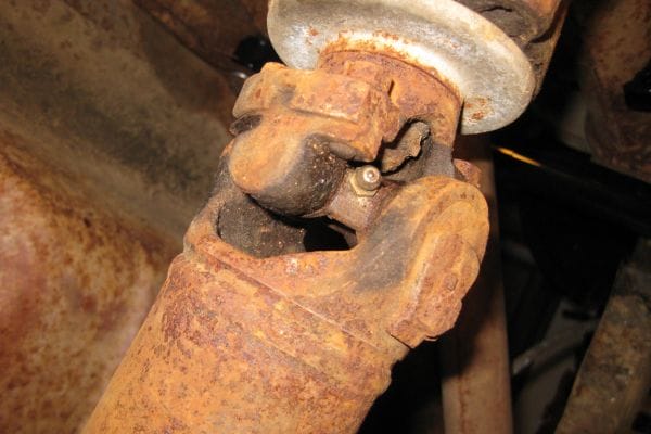
Visual Inspection Examine the grease fitting for visible signs of damage or debris. Look for dirt, rust, or old grease around the fitting. A clogged or worn fitting may have visible buildup or discoloration.

Check for Blockages To check for a clog, remove the grease gun and inspect the fitting using a small wire or needle to probe inside. If you encounter resistance, it’s likely clogged. If you can’t get any grease flow, it’s time to check for a more serious obstruction deeper within the fitting or lubrication passage.

Damage to the Fitting Over time, grease fittings can wear out or get damaged due to misuse, over-tightening, or exposure to harsh environments. Look for cracks, wear marks, or bent parts that could prevent the fitting from sealing properly.

Testing Grease Flow If a small amount of grease still flows out, it might suggest a partial clog or damage, meaning that the fitting isn’t fully functional but still working in a limited capacity. A complete failure will prevent any grease from being dispensed.

Common Symptoms of a Faulty Grease Fitting

Grease Not Reaching Key Components If you’re experiencing poor lubrication in parts that rely on grease fittings, like bearings or joints, this could be a sign that the fitting isn’t functioning correctly. Without grease reaching these components, you may notice unusual wear, increased friction, or overheating.

Excessive Wear or Overheating When machinery components aren’t adequately lubricated, they can become overheated and wear out quickly. If you notice any of these signs, it’s time to inspect your grease fittings. A failure to lubricate could result in costly damage and system breakdowns.

Frequent Blockages or Leaking If you constantly experience grease leakage or clogging at the same fitting, it might be a sign of a damaged or worn-out fitting that needs replacement. Fittings should seal properly to prevent leaks while ensuring grease flow.

Troubleshooting Your Grease Fitting

Step-by-Step Troubleshooting Guide for Grease Fitting Problems

Step 1: Check the Grease Gun Before assuming the grease fitting is the problem, ensure your grease gun is in good working condition. Check for any signs of damage, such as cracks or leaks, and ensure it’s properly primed with grease. Also, verify that the nozzle is securely attached.

Step 2: Inspect the Grease Fitting for Damage or Wear Look for obvious signs of wear or damage on the fitting itself. If the fitting is cracked, worn down, or misaligned, it might not accept grease properly. In this case, a replacement is necessary.

Step 3: Examine the Grease Pathway If the fitting and grease gun appear to be functioning correctly, the issue may lie in the grease pathway. Check for blockages or obstructions in the line leading to the fitting. You may need to remove any fittings, hoses, or tubes connected to the system to inspect this thoroughly.

Step 4: Assess Grease Flow Once you’ve confirmed the grease fitting and its immediate connections are intact, proceed to check if grease flows properly when pressure is applied. If it doesn’t, this could indicate a more serious blockage or damage inside the fitting or grease passageway.

Grease Fitting Won’t Grease

Inspecting the Grease Fitting and Grease Gun Connection

Ensure Proper Fit The connection between the grease fitting and grease gun should be tight and secure. Any loose connections can lead to grease leakage or poor grease flow. If the connection seems faulty, clean both the grease fitting and gun nozzle to ensure a proper seal.

Inspect for Leaks If grease leaks around the connection while pumping, it could indicate that the fitting’s seal is compromised, or the nozzle isn’t properly attached. Check for worn seals on both the fitting and grease gun, replacing them if necessary.

Check the Nozzle and Tip The nozzle and tip of the grease gun should fit snugly onto the fitting. If the tip is too large or small, it may not form a proper seal, making it difficult to inject grease. Use the correct size nozzle for the grease fitting you’re working with.

Checking for Obstructions in the Grease Pathway

Remove the Grease Fitting If there’s no grease flow despite a proper grease gun connection, carefully remove the grease fitting using the appropriate tool. Inspect the fitting’s interior and the grease passage for any obstructions, such as hardened grease, dirt, or debris.

Clear the Pathway Use a needle or specialized grease fitting cleaner to clear any debris from the fitting. If the fitting is excessively clogged, you might need to soak it in a degreaser solution to loosen the debris. Once cleared, reassemble and test the grease flow.

Check the Grease Line If the fitting seems clear but grease still isn’t flowing, inspect the grease line (hose or tube) for potential kinks, cracks, or obstructions. Ensure that grease can freely flow all the way from the grease gun to the fitting.

How to Test Grease Flow through the Fitting

Manual Test After checking the fitting and grease gun connection, manually apply pressure to the grease gun and observe whether grease flows freely. If the grease doesn’t flow, there could be a deeper issue with the fitting or its components.

Use a Clear Grease Hose If you’re still unsure about the flow, use a clear hose to connect the grease gun to the fitting. As you apply pressure, observe whether grease is visible moving through the hose. This can help you pinpoint any blockages or resistance in the system.

Alternative Testing Methods In some cases, testing grease flow by applying a small amount of air pressure to the line can help you identify hidden blockages. However, be careful not to apply too much pressure, as this can cause damage to the fitting or the components.

How to Repair a Grease Fitting That Won’t Take Grease

Simple Repairs You Can Do Yourself

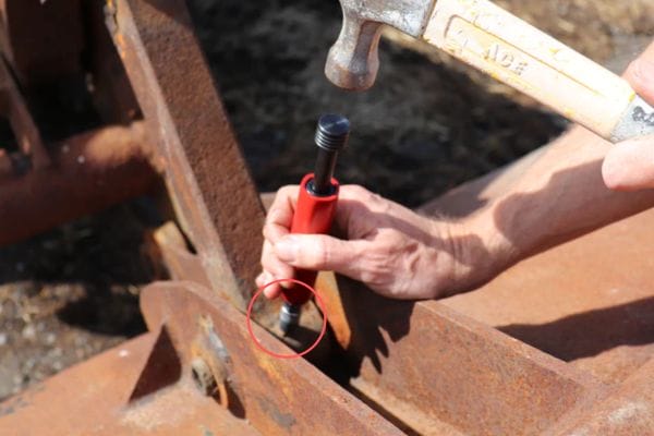
Clear Clogs with a Needle or Cleaning Tool If the grease fitting is clogged, one of the first steps is to use a grease fitting needle or cleaning tool to clear out the obstruction. Insert the needle into the fitting to break up debris or hardened grease. You can also use a specialized grease fitting cleaner that helps dislodge any buildup.

Clean and Lubricate the Fitting Sometimes, grease fittings may become stiff or sticky due to old grease or environmental debris. Clean the fitting with a wire brush or rag to remove dirt and grease. After cleaning, apply fresh grease to ensure smooth operation.

Check and Tighten the Fitting Loose fittings can prevent grease from flowing properly. Use a wrench to tighten the fitting, but be careful not to overtighten, as this could damage the fitting or the surrounding components. Ensure that the fitting is firmly connected and properly aligned.

Repair or Replace Seals If the fitting is leaking grease due to a worn seal, you may be able to repair it by replacing the seal or O-ring. Make sure the replacement is of the same size and material as the original to prevent further leaks and ensure a tight seal.

When to Replace the Grease Fitting: Signs It’s Beyond Repair

Cracks or Visible Damage If the grease fitting is cracked, deeply worn, or severely deformed, it’s likely beyond repair and needs to be replaced. Damaged fittings can lead to grease leakage, contamination, or even further damage to the equipment.

Persistent Blockages After Cleaning If the grease fitting remains clogged despite your best efforts to clean it, it may indicate that the internal pathway is permanently blocked or that there is structural damage. In this case, replacement is necessary.

Excessive Leakage If the fitting continues to leak grease even after cleaning and sealing, this suggests a more serious problem. Over time, repeated leakage can damage surrounding components, making replacement the best course of action.

How to Replace a Faulty Grease Fitting

Step 1: Prepare the Equipment Before replacing the faulty grease fitting, ensure that the equipment is turned off, and the area is safe to work in. Gather the necessary tools, including a wrench, a new grease fitting, and thread sealant if required.

Step 2: Remove the Old Fitting Use a wrench to carefully unscrew the damaged grease fitting. Be mindful not to damage the surrounding parts. If the fitting is stuck, try applying penetrating oil to loosen it before attempting to remove it again.

Step 3: Clean the Fitting Area Once the old fitting is removed, clean the area to ensure there is no debris, old grease, or rust that could affect the new fitting’s performance. You can use a rag or wire brush to clean the fitting hole.

Step 4: Install the New Grease Fitting Screw the new grease fitting into place, making sure it’s aligned correctly. Tighten it securely with a wrench, but avoid overtightening. If necessary, apply thread sealant to the threads to prevent leaks.

Step 5: Test the New Fitting Once the new fitting is installed, use your grease gun to apply grease. Ensure that grease flows smoothly and the fitting is functioning properly without any leaks or resistance.

Dealing with Grease Fitting Leakage

Understanding Grease Fitting Leakage and Its Causes

What Causes Grease Fitting Leaks? Grease fitting leakage can occur due to several factors, including worn or damaged seals, improper installation, or over-tightening of the fitting. The pressure from the grease gun can cause seals to rupture, leading to leaks around the fitting. Environmental debris, dirt, or hardened grease can also compromise the seal integrity.

Impact of Leakage on Equipment A leaking grease fitting may not only waste valuable lubricant but also lead to contamination of surrounding components. Over time, this can cause dirt and debris to enter machinery, damaging critical parts and decreasing overall performance. Regular leakage can lead to increased wear and tear, resulting in costly repairs.

Identifying Leakage Points Leakage can occur at the point of connection between the grease fitting and the grease gun, or where the fitting meets the machine. Pay attention to areas where grease seems to escape, as this can guide you to the source of the problem.

How to Fix a Leaking Grease Fitting

Step 1: Tighten the Fitting If the leak is coming from a loose connection, simply tightening the grease fitting may solve the problem. Use a wrench to secure the fitting without over-tightening, which could damage the threads or cause other issues.

Step 2: Replace Damaged Seals or O-Rings If the fitting’s seal or O-ring is worn or damaged, replacing it is the best solution. Make sure to choose the correct size and material of seal to match the manufacturer’s specifications for optimal performance and leak prevention.

Step 3: Clean and Clear Obstructions Dirt or hardened grease can compromise the seal, causing leaks. Clean the grease fitting and surrounding area thoroughly before replacing the seal. Clear any obstructions in the fitting that might prevent the seal from sitting correctly.

Step 4: Use Thread Sealant (If Necessary) For particularly stubborn leaks, you can apply a thread sealant designed for grease fittings. This will create an additional barrier to prevent grease from escaping around the fitting’s threads.

Preventing Future Leakage: Tips and Tricks

Regular Inspection and Maintenance Inspect your grease fittings regularly to ensure they remain clean and free of debris. Early detection of wear or damage can prevent future leaks and prolong the life of your equipment.

Proper Lubricant Application Avoid over-pressurizing the grease fitting with too much grease, as this can force seals to fail and cause leaks. Use the correct type and amount of lubricant to ensure optimal function without stressing the fitting.

Use High-Quality Fittings and Seals Invest in high-quality grease fittings and seals to minimize the risk of leakage. Cheaper fittings may degrade faster, leading to frequent repairs and leaks.

Ensure Proper Alignment Misaligned grease fittings are more likely to develop leaks. Ensure that all fittings are properly aligned with the lubrication path to prevent uneven pressure and leakage.

Conclusion

By staying on top of inspections and addressing issues early, you can extend the lifespan of your equipment, avoid costly repairs, and keep everything running efficiently. Regular lubrication and care for your grease fittings are essential for the long-term health of your machinery—ensuring it operates at its best and minimizes downtime.


FAQ

What should I do if my grease fitting won’t take grease?

If your grease fitting won’t take grease, start by inspecting the fitting for clogs or damage. Clean the fitting using a needle or cleaning tool to remove any obstructions. Tighten loose fittings and check for proper grease flow.

How do I know if my grease fitting is clogged?

Signs of a clogged grease fitting include resistance when using the grease gun, grease backing up or leaking, and no grease coming out when pressure is applied. If you notice these signs, inspect and clear the fitting using a needle or grease fitting cleaner.

Can I fix a leaking grease fitting myself?

Yes, you can fix a leaking grease fitting by tightening the connection, cleaning the fitting, and replacing any worn seals or O-rings. If the fitting is still leaking after these steps, it may need to be replaced.

What causes grease fittings to leak?

Grease fittings can leak due to damaged seals, worn-out fittings, improper installation, or over-tightening. External factors like dirt or debris can also compromise the seal, leading to leakage.

How often should I maintain my grease fittings?

It’s recommended to inspect and maintain your grease fittings regularly—at least once every few months, or more frequently in harsh environments. Regular maintenance helps ensure proper lubrication and prevents costly equipment damage.

When should I replace a grease fitting?

Replace a grease fitting if it’s severely damaged, cracked, or if cleaning and repairs don’t resolve the issue. If the fitting continually leaks or doesn’t allow grease to flow properly despite repairs, it’s time for a replacement.

What is the Alternative for BSP Thread banner

What is the Alternative for BSP Thread in Hydraulics?

BSP threads are a staple in hydraulic systems worldwide due to their durability and effectiveness in maintaining pressure-tight seals. Their ability to withstand extreme pressure without leakage makes them ideal for automotive, heavy machinery, and fluid power systems.

NPT Threads: A Popular Alternative for BSP Thread

What Are NPT Threads and How Do They Work?

NPT (National Pipe Thread) is a standard for threading commonly used in North America and other regions. It’s designed with a tapered geometry, where the threads gradually increase in diameter as they move along the length of the fitting. This taper creates a mechanical seal when the parts are tightened, making it effective in high-pressure applications. The threads are often coated with a sealing compound or tape to ensure an airtight seal, especially in fluid systems. NPT threads are widely used in piping and hydraulic systems for their reliability in preventing leaks and handling pressure fluctuations.

NPT Thread Geometry: Tapered Design and Its Sealing Mechanism

The taper in NPT threads is crucial for creating a pressure-tight seal. As the male and female threads are screwed together, the increasing diameter compresses the material at the interface, ensuring a secure connection. This taper angle typically ranges between 1° and 2°, providing a seal through mechanical compression. Unlike parallel threads that require additional sealing mechanisms, NPT threads inherently form a tight seal by the very nature of their design.

How NPT Threads Create a Tight Seal as They Are Tightened

The tapered nature of NPT threads forces the male and female parts to press against each other as they are tightened, allowing for a friction fit that is especially effective under pressure. This ensures that NPT fittings can withstand high-stress environments, making them suitable for hydraulics, plumbing, and fluid systems. The compression also helps accommodate minor imperfections in thread alignment, creating a more forgiving seal.

Common Uses of NPT Threads in Hydraulic Systems and Piping

NPT threads are widely used in industrial and hydraulic systems where fluid or gas needs to be securely contained. Common applications include hydraulic fittings, pipe fittings, valves, and pumps. The threads are essential in systems that require reliable sealing to prevent leaks under pressure, such as in the oil and gas, automotive, and water treatment industries. The versatility and ease of use have made NPT a popular choice for a wide variety of hydraulic applications.

Advantages of NPT Threads in Fluid Handling and Pressure Control

NPT threads are highly effective in fluid handling systems due to their ability to form a tight, reliable seal under high pressure. This makes them ideal for applications in which fluid leakage could result in system failure or safety concerns. The thread’s design also allows for ease of installation and disassembly, which is critical in industries where downtime for maintenance can be costly. Additionally, the tapered seal ensures the system maintains integrity even under varying pressures.

NPT vs BSPT Taper Threads

NPT vs BSPT: Key Differences and Compatibility Issues

Thread Design: The Difference Between Tapered NPT and BSPT Threads

While both NPT and BSPT are tapered threads designed for pressure-tight sealing, the main difference lies in their thread geometry. NPT threads have a 60-degree thread angle, whereas BSPT threads use a 55-degree angle. This minor difference in geometry can affect the fit and sealing capabilities when trying to mate NPT and BSPT fittings. The sealing mechanism also differs: NPT relies on compression to form a seal, while BSPT creates a seal due to the conical shape of the threads.

Sealing Mechanisms: How NPT Threads Rely on Compression vs. BSPT’s Cone-Shaped Design

NPT threads rely on the mechanical compression of the tapered threads, ensuring a tight seal as the parts are tightened. In contrast, BSPT threads form a seal through the deformation of the conical threads, creating a more specific compression seal that is especially effective in high-pressure applications. This difference can lead to challenges in sealing when mixing NPT and BSPT components.

Material and Application Compatibility: When NPT Works Better or Worse Than BSPT

NPT threads are commonly used in North American markets and are well-suited for applications requiring high-pressure sealing. However, BSPT threads are often used in international markets, particularly in Europe, and are sometimes preferred for certain fluid types or materials. Depending on the application, the material compatibility—such as with certain metals or high-temperature fluids—may determine which thread is more appropriate. NPT may outperform BSPT in certain fluid systems due to its compression-based sealing, but BSPT may be preferred in specific high-torque scenarios.

Potential Issues When Mixing NPT and BSPT Threads in Hydraulic Systems

Mixing NPT and BSPT threads is generally not recommended because of the differences in thread geometry and sealing mechanisms. Using mismatched fittings can lead to poor seals, leaks, and potential system failure. The misalignment of the threads can cause uneven pressure distribution, leading to a reduction in system performance. In some cases, adapting between the two thread types may require special fittings or adapters, but even then, ensuring a leak-proof connection can be difficult.

How to Properly Adapt Between NPT and BSPT in Critical Hydraulic Applications

When adapting between NPT and BSPT threads in critical hydraulic applications, it’s essential to use appropriate adapters that maintain the correct sealing mechanics for each type. For example, a fitting designed for both NPT and BSPT might offer the necessary taper for BSPT while providing the necessary compression for NPT threads. Sealing compounds or thread tapes may also be required to ensure the connection remains leak-proof. However, it’s generally better to standardize the entire system on either NPT or BSPT to avoid potential compatibility issues.

NPSM Thread: Another Viable Alternative

What is NPSM Thread and How Does it Compare to BSP?

NPSM (National Pipe Straight Mechanical) is a threading standard primarily used for mechanical connections. Unlike BSP, which uses tapered or parallel threads, NPSM threads are straight, with no taper. This makes NPSM unique in that it relies on mechanical compression, rather than sealing via thread tapering. NPSM threads are often used where high pressure or a more robust seal is needed, but they may not be as widely known or used as BSP threads in all regions. Key differences lie in how the threads engage and seal, with NPSM favoring mechanical compression over fluid sealing.

NPSM vs BSP: What Sets Them Apart in Terms of Design and Sealing

Thread Design: The main distinction between NPSM and BSP threads is that NPSM threads are straight, while BSP threads come in both tapered (BSPT) and parallel (BSPP) versions. This makes NPSM threads more suited for certain applications requiring a less complex seal.

Sealing Mechanism: BSP threads generally rely on the interaction of tapered or parallel threads for sealing, while NPSM threads require additional sealing mechanisms, such as compression rings or gaskets, to achieve a tight connection.

Application Scope: NPSM threads are typically used in mechanical connections where vibration and pressure may cause other thread types to fail, while BSP is more common in fluid-handling systems that require a reliable seal without extra sealing components.

Key Characteristics of NPSM Threads: Straight Threads with No Taper

NPSM threads are straight, with a consistent diameter along their length. This design simplifies the installation process compared to tapered threads, and provides flexibility in choosing sealing methods such as O-rings or gaskets. The straight thread design allows for a stronger, more secure mechanical fit in certain applications where tapering threads may be ineffective or difficult to manage.

How NPSM Threads Differ in Fitting Design, Thread Pitch, and Application Scope

Fitting Design: NPSM fittings usually require a complementary flanged or compression fitting to ensure a leak-free connection. This contrasts with BSP threads, which often use a simple male-female connection.

Thread Pitch: NPSM threads often feature finer thread pitches compared to BSP, providing a tighter and more secure mechanical hold in certain hydraulic applications.

Application Scope: NPSM threads are widely used in mechanical and industrial applications where reliability and high-pressure sealing are required, but may not always be suitable for fluid systems.

Why NPSM is Preferred in Certain Applications Over BSP Threads

Pressure Handling: In systems where high pressure or vibration is a concern, NPSM threads provide an advantage over BSP, as their design allows for more secure connections.

Flexibility in Sealing: The ability to pair NPSM threads with different sealing methods like gaskets, O-rings, and compression fittings makes them ideal for custom hydraulic systems.

Mechanical Reliability: NPSM’s mechanical compression seal ensures a strong, leak-free connection even in high-demand environments, where BSP might need additional sealing aids.

NPSM vs BSP: Key Considerations for Compatibility

Thread Geometry Differences: Straight vs Tapered, and Their Impact on Sealing

The key difference between NPSM and BSP threads lies in the thread design itself: NPSM is straight, while BSP is tapered (BSPT) or parallel (BSPP). This distinction affects how the threads engage and seal. NPSM requires additional sealing mechanisms, such as O-rings or compression fittings, while BSP can form seals through the thread geometry alone.

The Importance of Thread Alignment and Fitting

Proper alignment of threads is crucial for ensuring leak-proof connections. When adapting NPSM threads to BSP systems, it’s essential to ensure that the fittings are compatible and aligned to avoid leakage or damage to the threads. Misaligned threads can lead to cross-threading and poor sealing, impacting overall system performance.

When to Use NPSM Threads in Place of BSP

High-pressure applications: When dealing with high-pressure hydraulic systems, NPSM may be a better choice due to its mechanical compression sealing properties.

Mechanical or industrial applications: In mechanical systems where high vibration or movement is present, NPSM threads can provide a stronger, more reliable seal.

Customization needs: For systems requiring specific materials, sealing types, or installation conditions, NPSM threads offer greater flexibility.

Metric Thread Alternatives: Are They a Good Option?

What Are Metric Threads and How Do They Differ from BSP?

Metric threads, governed by international standards like ISO and DIN, are used globally across various industries, including hydraulics. Common thread profiles include the “M” series, which features a straightforward, uniform pitch and diameter. Unlike BSP threads, which may vary in design (BSPT or BSPP), Metric threads use a more consistent, standardized approach, making them ideal for precision manufacturing. The key difference between Metric and BSP threads lies in the thread pitch, diameter, and overall fitting design—Metric threads generally have finer threads and a more precise manufacturing tolerance. This results in better performance and compatibility with global systems, particularly in automotive, aerospace, and precision machinery.

Metric Ports

Pros and Cons of Metric Thread Alternatives in Hydraulics

Pros of Metric Threads:

Universality and Global Standardization: Metric threads are universally recognized, making them the preferred choice in international markets. They simplify the sourcing and replacement of components across borders.

Precision and Performance: The high manufacturing tolerances associated with Metric threads provide excellent sealing capabilities, ensuring efficient hydraulic performance.

Material Compatibility: Metric threads are highly compatible with various materials, including stainless steel, brass, and plastic, which are commonly used in hydraulic systems.

Ease of Sourcing: Due to their standardization, Metric fittings and components are widely available, making them easy to source in international markets, reducing lead times.

Cons of Metric Threads:

Adaptation Complexity: Converting to Metric threads from BSP or NPT systems can introduce complications, especially in existing systems that rely on other thread standards.

Availability of Fittings: In some regions, the availability of Metric fittings may be limited, particularly in markets where BSP or NPT is more common.

Compatibility Issues: Older hydraulic systems designed specifically for BSP threads may face compatibility issues when Metric threads are introduced.

Cost Considerations: Custom Metric fittings can be more expensive to manufacture or source, especially in regions where these standards are less common.

Making the Right Choice for Your System

How Threaded Fittings Affect the Performance of Hydraulic Systems

Threaded fittings are crucial to the overall performance of hydraulic systems. The right thread ensures a tight seal, allowing systems to operate at optimal pressure levels without the risk of leaks or system failure. Improper fitting selection can lead to mechanical failures, energy loss, and costly maintenance. Understanding the nuances between various thread types (BSP, NPT, NPSM, Metric) and selecting the most suitable option based on pressure, size, and material compatibility is essential for a well-functioning hydraulic system. Additionally, choosing the correct fitting can minimize installation time, reduce downtime, and increase the lifespan of components.

Sealing and Leak Prevention with Threaded Fittings

Sealing is one of the primary functions of threaded fittings in hydraulic systems. The integrity of the seal determines whether a system will perform efficiently and safely. BSP threads rely on the compression of tapered or parallel threads to form a seal, whereas alternatives like NPT threads rely on the taper for a leak-proof connection. Metric and NPSM threads, on the other hand, often require additional sealing mechanisms such as gaskets or O-rings. In high-pressure systems, ensuring a tight seal is critical to prevent fluid leaks, which can lead to energy loss, contamination, or even catastrophic failure. Choosing the right thread type that ensures the best sealing solution for your specific application is paramount.

Conclusion

Whether you opt for BSP, NPT, NPSM, or Metric threads, understanding the specific benefits of each thread type and how they integrate with your components will help you make the right choice.


FAQ

What is the difference between BSP and NPT threads?

The key difference lies in the thread design, with BSP threads using a different angle and pitch compared to NPT.

Can I mix BSP and NPT fittings in the same hydraulic system?

Mixing BSP and NPT fittings is not recommended, as they have different thread geometries and sealing methods. Mixing them can lead to leaks, poor sealing, and system failure. Adapters are available, but they should be used with caution.

What are NPSM threads, and when should I use them?

NPSM (National Pipe Straight Mechanical) threads are straight threads commonly used in mechanical connections. They are often preferred in applications where sealing is achieved through compression rather than tapering.

When should I use Metric threads instead of BSP threads?

Metric threads are ideal when you need international compatibility and precise tolerances. They are commonly used in global industries like automotive and aerospace.

How do I ensure leak-proof connections with threaded fittings?

To ensure a leak-proof connection, it’s essential to choose the correct thread type for your hydraulic system and ensure proper sealing. For BSP and NPT threads, make sure fittings are tightened to the correct torque specifications. For Metric and NPSM threads, additional sealing mechanisms like O-rings or gaskets may be necessary.

Are there any disadvantages to using BSP threads in modern hydraulic systems?

BSP threads may face compatibility issues with certain international standards, and their sealing can sometimes be less reliable compared to alternatives like NPT.

How Do Camlock Fittings Work banner

How Do Camlock Fittings Work? A Simple Guide

Camlock fittings, also known as cam and groove couplings, are a type of quick-connect coupling widely used to join hoses, pipes, and other fluid transfer equipment. They consist of two parts: a male coupler and a female adapter, which are connected using a locking mechanism that allows for a secure, leak-proof connection.

The Basics of Camlock Fittings

Camlock fittings are a type of quick-connect coupling that are widely used for fluid transfer. The mechanism behind how these fittings work is both simple and effective, making them an essential component in industries that require fast, secure, and reliable fluid handling.

Understanding the Camlock Coupling Mechanism

At the heart of a camlock fitting is its cam-locking mechanism. This system consists of a male coupler and a female adapter. The male coupler features a set of grooves along the outer edge, while the female adapter has cam arms or levers that engage with these grooves. To make a connection, the male and female parts are brought together, and the cam levers are pressed down over the grooves. Once the levers are engaged, they apply pressure to lock the two components firmly in place.

The design of the camlock system is incredibly efficient for quick-connect and quick-disconnect operations. The cam arms pivot over the coupler grooves and form a tight, leak-proof connection without requiring additional tools. This allows operators to secure or release the fitting with minimal effort, ensuring a smooth workflow in fluid transfer applications.

industrial fittings Camlock Topa

Key Components of a Camlock Fitting

Each camlock fitting consists of a few key components that work together to form a reliable and durable connection.

Male Coupler: This part features a grooved edge designed to fit into the female adapter. The grooves are where the cam levers engage to create a tight seal. Male couplers come in various sizes and materials, such as stainless steel, brass, and aluminum.

Female Adapter: The female part of the camlock fitting is designed to mate with the male coupler. It typically has a smooth interior that corresponds to the outside diameter of the male coupling. The female adapter houses the cam arms or levers, which are the moving parts responsible for locking the connection.

Cam Levers: The cam arms, or levers, are essential for locking the coupling into place. They are pressed down over the grooves of the male coupler, and once engaged, they provide the mechanical force needed to keep the connection secure under pressure.

Seals and Gaskets: To prevent leaks, camlock fittings often include seals or o-rings that sit between the male and female components. These seals form a barrier that prevents fluids from escaping, ensuring that the connection remains tight and secure. The material of the seals may vary, with common options being rubber, PTFE, or silicone, depending on the fluid being handled.

Locking Pins or Locks: Some camlock fittings incorporate additional locking mechanisms, such as pins or locks, to further secure the connection, especially in high-pressure or high-flow applications.

How Camlock Fittings Ensure Secure Connections

The reliability of camlock fittings lies in their robust design, which ensures that the connection is secure and leak-free. When the cam levers are pressed down over the male coupler’s grooves, the locking arms apply a strong clamping force. This clamping ensures that the connection remains tightly sealed even when exposed to high pressures, fluctuating temperatures, or rough handling.

In addition to the cam-locking mechanism, the seals or gaskets in the fitting play an important role. As the two parts of the camlock fitting come together, the seals compress, creating a strong barrier against fluid leakage. This is particularly important in applications where the safe containment of liquids or gases is essential, such as in chemical processing, fuel transfer, or food production.

Another key aspect of the secure connection is the material quality of the camlock fittings. Materials such as stainless steel and brass are corrosion-resistant, making them ideal for harsh environments where exposure to chemicals, moisture, or extreme temperatures could cause other materials to degrade over time. The combination of quality materials, effective sealing, and the cam-locking mechanism guarantees that camlock fittings provide a secure and long-lasting connection in a variety of industrial applications.

The ease of connection and disconnection also enhances the overall safety and security of the system. Operators can quickly disconnect camlock fittings in emergency situations or for routine maintenance, and the connection will remain secure while in use, offering peace of mind throughout the entire process.

Types of Camlock Connectors

Camlock fittings are designed to provide reliable, quick connections for a wide variety of applications. The designations A through F refer to different types of camlock connectors, each offering unique combinations of male and female parts to suit specific fluid handling requirements. Let’s take a closer look at each type:

Type A: Male Adapter with Female Thread

The Type A camlock fitting features a male adapter that is fitted with a female thread on the opposite side. This configuration is commonly used in applications where a threaded connection is needed on one side of the coupling. Type A fittings are typically paired with female-threaded connections on equipment or piping systems, making them ideal for environments where a secure, threaded connection is required.

Type B: Female Coupler with a Male Thread

The Type B fitting has a female coupler that is fitted with a male thread. This makes it ideal for connecting to threaded equipment or pipes, where a male-threaded adapter is required to complete the connection. The design allows for a secure seal when connecting to male-threaded systems.

Type C: Female Coupler with a Hose Tail

Type C connectors have a female coupler and a hose tail, making them perfect for fluid transfer applications where a hose needs to be securely attached. The hose tail end allows for easy hose connection, while the female coupler provides a robust, leak-free seal.

Type D: Female Coupler with a Female Thread

Type D fittings feature a female coupler with a female thread on the opposite end. This type is typically used when you need to connect a male-threaded pipe or equipment to a female-threaded system. It’s often used when two female threaded components need to be connected securely.

Type E: Male Adapter with a Hose Tail

The Type E camlock fitting includes a male adapter on one side and a hose tail on the other, making it ideal for applications where a hose needs to be connected to a male-threaded pipe or valve. The hose tail end provides a secure fit for flexible hoses, while the male adapter ensures a tight seal with female-threaded equipment.

Type F: Male Adapter with a Male Thread

The Type F camlock fitting features a male adapter with a male thread. This configuration is used when you need to connect a female-threaded pipe or equipment to male-threaded connections, often in systems that require male-to-male connections for secure fluid handling.

Choosing the Right Camlock Connector for Your Needs

Selecting the right camlock fitting involves carefully considering several factors to ensure optimal performance, durability, and safety for your fluid handling needs. Here are some key factors to consider when choosing the best camlock connector for your application:

Material Compatibility

Stainless Steel: Best for use in corrosive or high-temperature environments. Stainless steel camlocks offer superior resistance to both corrosion and heat, making them ideal for harsh applications such as chemical processing and offshore oil rigs.

Brass: Ideal for non-corrosive applications like fuel transfer, as it provides excellent resistance to corrosion from chemicals and oils.

Aluminum: A lightweight and cost-effective option, making aluminum camlocks ideal for less aggressive environments like water transfer or low-pressure systems.

Size and Pressure Ratings

The size of the camlock fitting must match the hose diameter and flow rate required by your system. The pressure rating of the camlock fitting should be checked to ensure it can handle the operational load without failure. Larger sizes and high-pressure ratings are often required for heavy-duty applications like oil and gas or industrial manufacturing.

Seal Material

Camlock fittings use different types of seals (often O-rings) to ensure a tight, leak-proof connection. The material of the seal should be compatible with the fluids being transferred. For example:

EPDM seals are excellent for water and general-purpose use.

Viton seals are suitable for oils, chemicals, and high-temperature applications.

Application Type

Consider whether you need a quick-connect fitting for frequent disconnections, or whether a permanent or semi-permanent connection is sufficient. Camlock fittings are often the go-to choice for systems where rapid connections and disconnections are required, such as agriculture, firefighting, and water management systems.

Regulations and Standards

It’s essential to ensure that your camlock fittings meet relevant industry standards such as ISO or ANSI to guarantee safety and reliability. These standards help ensure the fittings are suitable for use in specific applications, particularly when handling hazardous or pressurized fluids.

How Do Camlock Fittings Work?

The Functionality of Camlock Connectors

Camlock connectors work on a simple yet highly efficient quick-connect system that allows users to securely connect and disconnect hoses, pipes, or other fluid transfer equipment without requiring special tools or excessive force. The connectors operate using a male coupler and a female adapter, which are joined together using the camlock coupling mechanism.

When connecting, the male coupler features a grooved end that fits into the female adapter. Once inserted, the user operates the lever cams, which are located on the female adapter. The cam levers, when pressed down, lock into the grooves on the male coupler, effectively sealing the connection. This action ensures a secure and tight bond, preventing fluid leakage or accidental disconnections during transfer.

The coupling mechanism is designed to be user-friendly and quick, making it ideal for environments where fluid transfer needs to be done rapidly and with minimal downtime.

How Do Camlock Fittings use

The Role of Camlock Seals in Fluid Transfer

One of the key components that ensures leak-proof performance in camlock fittings is the use of seals. These seals, usually made from rubber or elastomeric materials, are located within the female adapter or around the male coupler. They play a crucial role in ensuring that the connection remains tight even under pressure.

When the camlock coupling is locked in place, the seals compress between the male and female parts, creating a secure barrier that prevents fluid leakage. This is especially important in applications where the transfer of chemicals, fuels, or other hazardous fluids is involved. The seals also act as a protective barrier against contaminants, ensuring that the fluids being transferred remain pure and uncontaminated.

High-quality seals made of resistant materials are essential for long-lasting and reliable performance, particularly in harsh conditions. The sealing properties also ensure the integrity of the fluid transfer system, reducing the risk of spills, environmental hazards, and costly downtime.

The Camlock Lock Mechanism Explained

The lock mechanism is what sets camlock fittings apart from many other types of industrial couplings. The camlock lock mechanism involves the use of cam levers or arms that are attached to the female adapter. These levers serve as a locking system that secures the connection between the male coupler and female adapter.

The process works as follows:

Insertion: The male coupler is inserted into the female adapter, with the groove on the male fitting aligning with the camlock levers on the female adapter.

Lever Action: The user pushes down on the cam levers, which apply pressure to the male coupler. The levers engage with the grooves on the male fitting, locking the two pieces together.

Secured Connection: Once the levers are in place, the connection is secured. The locking mechanism ensures that the coupling remains intact, even under high pressure or movement, and prevents accidental disconnections.

The locking mechanism offers several benefits:

It provides a tight seal, preventing fluid leakage.

It eliminates the need for extra tightening tools, saving time and effort.

It ensures safety by keeping the connection intact, reducing the risk of spills or accidents.

This lock mechanism makes camlock fittings ideal for heavy-duty applications and environments where a reliable connection is crucial.

How the Camlock Coupling Quickly Connects and Disconnects

One of the standout features of camlock fittings is the ability to quickly connect and disconnect hoses and pipes without the need for tools or excessive force. This fast coupling process makes camlock fittings especially valuable in industries where time is of the essence, such as firefighting, chemical transfer, or construction.

Here’s how the quick-connect feature works:

Initial Setup: The male coupler is aligned with the female adapter. Depending on the type of camlock fitting, this can involve aligning grooves and seals for proper fitment.

Engagement: The user presses the cam levers down to lock the two parts in place. As the levers engage with the grooves, they apply pressure, ensuring a secure, leak-proof connection.

Sealing: The seals inside the fitting compress, ensuring that there is no room for fluid leakage, even when the system is under pressure.

Disconnection: When it’s time to disconnect, the process is equally simple. The user lifts the cam levers, which release the locking mechanism, allowing the male coupler to be easily removed from the female adapter.

This design eliminates the need for screws, bolts, or other complex joining mechanisms, making it a preferred solution when rapid and frequent connections are required.

The ability to quickly disconnect also reduces downtime in high-demand environments and minimizes the risk of fluid backflow or accidental contamination when the fittings are being removed.

Camlock Fittings vs Other Types of Industrial Fittings

When it comes to choosing the right industrial fitting, it’s essential to compare camlock fittings with other popular types. While camlock fittings are renowned for their quick-connect functionality and versatility, there are other fitting options like threaded fittings and quick disconnect fittings that may suit specific needs depending on the application. Let’s explore how camlock connectors stack up against these alternatives.

How Camlock Connectors Compare to Threaded Fittings

Threaded fittings and camlock connectors are two of the most commonly used types of industrial fittings. They each have their advantages, but camlocks stand out in several ways:

Ease of Use: One of the most significant advantages of camlock fittings over threaded fittings is their quick-connect and quick-disconnect capabilities. With threaded fittings, the connection process requires aligning the threads, tightening them with tools, and ensuring the proper seal. In contrast, camlock fittings lock into place with a simple lever mechanism, offering faster assembly and disassembly without the need for tools. This makes camlocks a more efficient choice for applications that require frequent or rapid connection and disconnection.

Leak Resistance: Both threaded and camlock fittings can be leak-resistant, but camlocks provide a better seal in some situations, especially when coupled with high-quality seals (such as EPDM or Viton). The pressure from the cam lever ensures a tight fit, which may outperform threaded connections that are prone to loosening over time or under vibration.

Application Versatility: Threaded fittings are often used for permanent or semi-permanent connections in piping systems where a robust, long-term connection is needed. Camlock fittings, on the other hand, excel in temporary connections—ideal for industries like agriculture, firefighting, and fluid transfer systems, where quick, secure, and frequently adjusted connections are necessary.

Durability: Threaded fittings tend to be more durable for high-pressure systems or where a permanent, tight seal is required. However, camlock fittings are incredibly durable in their own right, especially in heavy-duty applications like oil and gas or chemical handling, thanks to the use of materials like stainless steel or aluminum.

In summary, threaded fittings are ideal for permanent, high-pressure applications, while camlock connectors provide speed, ease of use, and flexibility in fluid transfer systems requiring frequent connections.

Camlock vs Quick Disconnect Fittings: What’s the Difference?

Quick disconnect fittings (also known as quick-connect fittings) are similar to camlock fittings in that they both offer the convenience of fast connection and disconnection. However, the mechanisms and applications for each type differ slightly.

Mechanism

Camlock Fittings: Utilize a cam lever system that secures the connection by pressing down on the levers that engage with the grooves of the male coupler. This creates a tight, leak-proof seal that is easy to engage and disengage.

Quick Disconnect Fittings: Usually use a push-button or spring-loaded mechanism. You push the button to release the coupling, or sometimes, you simply pull the two parts apart. They are designed for quick coupling and uncoupling but generally lack the positive-locking feature of camlocks.

Security and Sealing

Camlocks: Known for stronger, more secure connections. The cam-locking mechanism provides extra pressure on the seal, reducing the chances of leakage under pressure. The quick-connect feature is highly efficient, yet the cam lever ensures the connection is tighter and more stable than most push-button quick disconnects.

Quick Disconnects: These can be less secure, as the connection might not be as tight as camlocks, depending on the specific model. Many quick-disconnect fittings rely on a simple spring or ball lock, which can sometimes result in less security compared to a camlock fitting’s positive-locking mechanism.

Applications

Camlock Fittings: Ideal for heavy-duty applications, including fluid transfer, industrial manufacturing, agriculture, and firefighting, where secure connections are paramount, and there’s a need for frequent and quick disconnects. Camlocks are typically used for more rigorous tasks involving high pressure and high flow rates.

Quick Disconnect Fittings: Often used in applications that require lower pressure and medium flow. These fittings are common in smaller-scale operations like HVAC systems, pneumatic systems, and water supply lines. They provide convenience but are not usually designed for extreme conditions.

Durability and Material

Camlock Fittings: Typically made from durable materials like stainless steel, brass, or aluminum, making them well-suited for high-pressure systems, harsh chemicals, and extreme temperatures.

Quick Disconnect Fittings: While available in similar materials, these tend to be less durable when compared to camlocks, especially under heavy-duty conditions.

Conclusion

When you choose the right camlock connector, you’re not just investing in a fitting, but ensuring the smooth operation and safety of your fluid systems


FAQ

What are camlock fittings used for?

Camlock fittings are used for quick and secure connections in fluid transfer systems. They are commonly used in industries such as agriculture, firefighting, oil and gas, and chemical processing for connecting hoses, pipes, and equipment without the need for tools.

How do camlock fittings work?

Camlock fittings work by using a male coupler and a female adapter. The male coupler fits into the female adapter, and cam levers are engaged to lock the connection, ensuring a tight, leak-proof seal.

What materials are camlock fittings made from?

Camlock fittings are typically made from stainless steel, brass, aluminum, and plastic. The material choice depends on the application, with stainless steel being best for high-temperature or corrosive environments and brass for fuel transfer.

Can camlock fittings handle high pressure?

Yes, camlock fittings are designed to handle high-pressure fluid transfer. However, the pressure rating can vary depending on the material and size of the fitting, so it’s important to choose a fitting with the appropriate pressure rating for your system.

How do I choose the right camlock fitting for my application?

To choose the right camlock fitting, consider factors like material compatibility, hose diameter, pressure ratings, and the specific application requirements.

Are camlock fittings easy to install?

Yes, camlock fittings are easy to install due to their quick-connect mechanism. You simply align the male and female parts, engage the cam levers, and the connection is secured without the need for tools.

Clogged Grease Fitting banner

Clogged Grease Fitting: Common Causes and Easy Solutions

Grease fitting is a small component in machinery where grease is injected to lubricate parts and reduce friction. When these fittings become clogged, grease cannot flow properly, leading to excessive wear, overheating, and potential failure of machinery.

Common Causes of Clogged Grease Fittings

Grease fittings are vital components in maintaining the smooth operation of machinery by ensuring that moving parts are properly lubricated. However, when these fittings become clogged, it can lead to severe performance issues and even equipment failure. There are several common causes of clogged grease fittings, each of which affects the flow of grease and ultimately impacts machine efficiency.

Grease Quality and Viscosity: Why It Matters

The quality and viscosity of the grease you use play a critical role in ensuring that your machinery stays properly lubricated. Grease with the wrong viscosity can cause flow issues in the system, while low-quality grease can degrade over time. When grease thickens or hardens, it can block grease fittings, preventing grease from flowing to critical parts.

For optimal performance, always ensure that the grease used matches the manufacturer’s specifications for viscosity. High-quality, compatible grease can prevent clogs and ensure that machinery operates smoothly and efficiently.

Environmental Factors

External environmental conditions have a significant impact on grease quality and its ability to flow through fittings. Dust, dirt, moisture, and extreme temperatures can degrade grease, causing it to thicken or harden, ultimately leading to blockages.

Dust and Dirt: These contaminants can enter the grease fitting if seals are damaged or improperly sealed, leading to contamination within the system. This can result in the grease becoming thick or gritty, obstructing the flow.

Moisture: Water ingress into the grease system can break down grease, causing it to become watery or emulsified, which reduces its effectiveness and leads to clogging.

Extreme Temperatures: Very high or low temperatures can change the consistency of grease. In cold conditions, grease can become too thick to flow properly, while high temperatures can cause it to break down faster and form sludge.

Regular maintenance and using grease that is formulated to withstand specific environmental conditions can help mitigate these issues.

Grease Fittings rust

Over-lubrication and Its Impact on Grease Flow

Over-lubricating machinery can be just as damaging as under-lubricating it. When too much grease is applied, it leads to over-pressurization in the lubrication system. Excess grease can force contaminants into the grease fitting, leading to blockages. Additionally, over-lubrication may cause the grease to harden or become difficult to pump through the system, effectively obstructing the flow.

Furthermore, over-pressurization can damage equipment seals, leading to leaks and further contamination of the lubrication system. To prevent over-lubrication, always follow manufacturer recommendations for grease amounts and reapplication frequency.

Poor Lubrication Practices: The Hidden Culprits

Incorrect lubrication practices are often overlooked but are major contributors to clogged grease fittings. These practices include:

Using the Wrong Grease: Using grease that isn’t compatible with the machinery or environment can cause blockages. For example, grease that is too thick may clog the fitting, while grease that’s too thin may fail to provide sufficient lubrication.

Inconsistent Greasing Schedule: Failing to grease machinery on a regular basis, or over-greasing, can both lead to clogged fittings. Without a consistent greasing routine, grease may harden, become contaminated, or not reach the necessary parts, leading to blockages.

Establishing a clear lubrication protocol based on manufacturer guidelines can go a long way in preventing these issues.

Inadequate Maintenance: Failing to Inspect and Clean Grease Fittings

Regular inspection and cleaning are essential for preventing clogs. Over time, dirt, hardened grease, and other debris can accumulate around the grease fitting, blocking grease flow. Without proper maintenance, grease fittings can become difficult to service, resulting in inadequate lubrication and increased wear on equipment.

Make it a habit to inspect grease fittings at regular intervals, ensuring that the fittings are clean and free of debris. Cleaning fittings before lubrication ensures that grease flows freely to where it is needed.

External Contaminants: Dust, Dirt, and Water in Your Grease System

External contaminants are one of the most common causes of clogged grease fittings. Dust, dirt, and water can easily enter the grease system if the fitting seals are compromised or if the system is improperly sealed.

Dust and Dirt: If the environment is dusty or gritty, dirt can enter the grease fitting and mix with the grease, causing it to thicken or form a sludge. This can clog the fitting and reduce lubrication efficiency.

Water: Water ingress is another major concern. Even a small amount of water can cause grease to degrade, making it less effective and prone to clogging.

Regularly inspect seals, replace damaged fittings, and use protective covers to prevent contaminants from entering the system.

Aging and Worn-Out Fittings: Time for a Replacement?

Over time, grease fittings can become worn or damaged, especially if they are frequently exposed to harsh operating conditions. As fittings age, they may corrode, rust, or develop cracks, compromising their ability to properly accept grease.

Corrosion: Corroded fittings can block grease flow and reduce the effectiveness of lubrication, leading to increased wear on equipment.

Seal Failure: Fittings that are no longer sealed properly can allow contaminants like dirt and water into the grease system, leading to clogs and lubrication issues.

If a grease fitting is damaged or corroded beyond repair, it’s crucial to replace it promptly to ensure that grease can flow freely and continue to lubricate the machinery.

Signs Your Grease Fitting is Clogged

Grease fittings are essential for maintaining smooth operation in machinery by ensuring that moving parts remain properly lubricated. When these fittings become clogged, they prevent grease from reaching critical components, leading to various operational issues. Here are some key signs that indicate a clogged hydraulic grease fitting:

Difficulty Greasing: When the Grease Gun Won’t Work

One of the most obvious signs of a clogged hydraulic grease fitting is difficulty when trying to grease the component. If the grease gun doesn’t dispense grease properly or you encounter resistance when applying grease, it likely indicates a blockage or restriction in the fitting. This could be due to hardened grease, debris, or other obstructions inside the fitting.

What to Check: Inspect the grease gun and nozzle to ensure they’re in good condition and that the fitting is aligned properly. If the grease gun is functioning correctly and the fitting is still not accepting grease, it’s time to investigate further for blockages.

Unusual Noises or Vibrations in Your Equipment

A clogged hydraulic grease fitting can prevent proper lubrication of moving parts, leading to increased friction. When parts rub against each other without sufficient grease, they can produce unusual noises such as squeaks, grinding sounds, or vibrations. These noises often signal that the components are under stress, which can lead to accelerated wear and eventual failure.

What to Listen For: Pay attention to any changes in sound or vibrations coming from the machinery. Unusual sounds are a clear indication that the lubrication system is not functioning as it should, often due to a clogged fitting.

Grease Leakage Around the Fitting

If a grease fitting is clogged, it can cause excessive pressure to build up within the lubrication system. This pressure buildup can force grease to leak out from around the fitting, resulting in grease spills or visible leakage. A properly functioning fitting should accept the grease without forcing it out.

What to Look For: Inspect the area around the grease fitting for signs of grease leakage. If you notice grease oozing out from the fitting, it’s a sign that the fitting is not properly accepting grease, likely due to a blockage or damage.

Visible Blockages or Residue Around the Fitting

Clogged hydraulic grease fittings may exhibit visible signs of buildup. If you notice hardened grease, dirt, or residue accumulating around the fitting, it’s an indication that the grease flow has been obstructed. This is often caused by old or contaminated grease, dirt ingress, or lack of regular maintenance.

What to Check: Clean the grease fitting to inspect for hardened or contaminated grease. If you find that grease is not flowing freely, or if you see visible obstructions, it’s time to clear the fitting and restore proper lubrication.

Reduced Equipment Performance and Increased Wear

When grease fittings are clogged, machinery often operates with insufficient lubrication, leading to increased friction between moving parts. This can result in reduced equipment performance, slower operation, or even complete breakdowns due to excessive wear. Over time, a clogged hydraulic grease fitting will cause parts to wear out faster, leading to more frequent repairs and costly downtime.

What to Observe: Monitor the overall performance of the equipment. If the machinery shows signs of reduced speed, efficiency, or responsiveness, combined with higher-than-usual temperatures, it may be due to inadequate lubrication from a clogged hydraulic grease fitting. This can also lead to visible wear on bearings, joints, or other moving parts.

Preventing Clogged Grease Fittings

Clogged hydraulic grease fittings are a common problem that can significantly affect the performance and longevity of machinery. Preventing clogs before they occur requires a proactive approach to maintenance, proper lubrication practices, and selecting the right components for the job.

Establishing a Regular Grease Fitting Maintenance Routine

A consistent maintenance routine is the foundation for preventing clogged hydraulic grease fittings. By making inspection and cleaning a regular part of your equipment maintenance schedule, you ensure that grease fittings remain free from debris and function properly. A maintenance routine can include:

Inspecting fittings for visible damage, cracks, or signs of wear.

Cleaning fittings before lubrication to remove any accumulated dirt or hardened grease.

Checking for proper grease flow to ensure that grease is being distributed evenly and without resistance.

By staying on top of these tasks, you can catch potential issues early and prevent more severe blockages or wear.

Selecting the Right Grease for Your Machinery

Not all grease is created equal, and using the wrong type can contribute to clogging issues. The grease you choose should be carefully selected based on the specific requirements of your machinery. Key factors to consider include:

Viscosity: Choose grease with the correct thickness to match your machine’s operating conditions. Grease that is too thick can clog fittings, while grease that is too thin may not provide sufficient lubrication.

Temperature Resistance: Consider the operating temperature range of your machinery. Grease that isn’t temperature-resistant enough may degrade or thicken over time, causing blockages.

Material Compatibility: Ensure the grease is compatible with the materials used in your equipment, such as seals, bearings, and metal components. Incompatible grease can cause damage to parts or lead to clogging.

Using the correct grease helps ensure consistent lubrication and reduces the risk of clogging due to grease degradation.

fix Clogged Grease Fitting

Importance of Grease Fitting Inspection and Cleaning

Routine inspection and cleaning of grease fittings are crucial steps in preventing clogs. Regularly checking fittings for any signs of blockage, damage, or contamination will help you catch issues before they escalate. Here’s why it’s important:

Signs of Damage: Look for cracks or worn-out fittings that may allow contaminants to enter the grease system.

Preventing Contamination: Clean grease fittings before applying new grease to remove any old or contaminated grease, dirt, or debris.

Ensuring Proper Flow: Inspect fittings to ensure they allow grease to flow freely without resistance, ensuring all components are adequately lubricated.

By cleaning the fittings and inspecting for damage, you can keep the grease system running at peak performance and prevent clogs from developing.

Using Automatic Lubrication Systems to Minimize Human Error

Automatic lubrication systems are designed to deliver precise, consistent amounts of grease to each fitting, reducing the chances of clogging caused by human error. These systems help by:

Eliminating Over-greasing: Automatic systems are calibrated to apply the right amount of grease, preventing over-pressurization and the risk of forcing contaminants into the fitting.

Reducing Under-greasing: Automated systems ensure that each part gets lubricated at the correct frequency, preventing parts from running dry and wearing out.

Using the Right Grease: Automatic systems can be set up to use the correct type of grease for different machinery, ensuring compatibility and reducing the risk of clogging.

While automatic lubrication systems are an investment, they can significantly reduce maintenance costs and improve equipment performance over time by ensuring that grease is applied correctly and consistently.

Proper Grease Gun Usage to Avoid Over-pressurization

When using a grease gun, it’s important to apply the right amount of pressure to avoid over-pressurizing the system. Over-pressurization can force contaminants into the grease fitting, cause the grease to leak, or even damage seals and components. To avoid these issues:

Avoid Excessive Force: Apply grease at a steady, controlled pressure. If resistance is encountered, stop and check for possible blockages or damaged fittings before continuing.

Monitor Pressure: Use a grease gun with a pressure gauge to monitor and control the amount of pressure being applied, ensuring that the fitting does not become over-pressurized.

Follow Manufacturer Recommendations: Always adhere to the equipment manufacturer’s specifications for grease application pressure, as applying too much force can cause serious damage.

By using the grease gun correctly and carefully, you can prevent issues such as grease leakage and clogged fittings that result from over-pressurization.

Avoiding Contaminants: Protecting Your Grease System from Dirt and Water

Contaminants like dirt and moisture can quickly degrade the quality of grease, leading to clogs and system failures. To prevent these contaminants from entering the grease system, take the following precautions:

Inspect Seals Regularly: Ensure that the seals on grease fittings are intact and not worn out. Damaged seals allow dirt and water to infiltrate the lubrication system, causing contamination.

Keep the System Clean: Always clean the area around the grease fitting before applying grease to avoid introducing dirt or dust into the system.

Use Protective Covers: Consider using protective covers for grease fittings to shield them from dirt, dust, and moisture, especially when machinery is used in harsh environments.

Step-by-Step Guide

When a grease fitting becomes clogged, it can lead to inadequate lubrication, causing friction, wear, and potential damage to your equipment. Fixing a clogged hydraulic grease fitting requires a systematic approach to safely clear the blockage and restore the proper flow of grease.

Step 1: Identify the Problem and Assess the Damage

Before taking any action, it’s essential to confirm that the grease fitting is indeed clogged. Common signs of a clogged hydraulic grease fitting include:

Difficulty greasing: If you’re having trouble applying grease or the grease gun doesn’t dispense grease properly, the fitting may be obstructed.

Leakage: Excessive pressure buildup due to a clog can cause grease to leak around the fitting.

Unusual equipment behavior: If your equipment is making unusual noises, vibrating, or experiencing reduced performance, it may be a result of inadequate lubrication due to a clogged hydraulic grease fitting.

Once you identify the issue, assess whether the blockage is recent or has been building up over time. This can help you determine how severe the clog might be.

Step 2: Use a Grease Gun to Apply Pressure and Clear the Blockage

The first attempt to fix the clog is to apply pressure using a grease gun. This is a simple and effective method for clearing minor blockages. Here’s how to do it:

Prepare the grease gun: Ensure the grease gun is filled with the correct type of grease for your equipment.

Attach the nozzle to the fitting: Ensure a tight seal between the grease gun and the grease fitting.

Apply steady pressure: Begin pumping grease into the fitting. The force of the grease should help push the blockage out. Be careful not to over-pressurize the fitting, as this can damage seals or cause grease to leak.

Monitor the grease flow: If the grease starts flowing freely, the blockage is cleared. If it doesn’t, proceed to the next step.

Step 3: Apply Heat to Loosen Clogged Grease

If the grease fitting is still clogged after attempting to use the grease gun, the blockage may be caused by hardened grease. Applying heat can soften the grease and make it easier to clear. Here’s how to safely apply heat:

Use a heat gun or torch: Aim the heat at the clogged fitting and surrounding areas. Be cautious with the amount of heat to avoid damaging the fitting or surrounding parts.

Heat the fitting for a few minutes: Gradually warm the fitting and the surrounding area to soften the hardened grease inside.

Test the grease gun again: After applying heat, try pumping grease through the fitting once more. The softened grease should help clear the blockage.

Step 4: Use a Solvent or Grease Removal Tools for Stubborn Blockages

If heat doesn’t work, you may need to use a solvent or specialized tools to break up and remove the blockage. Here’s how to proceed:

Apply a grease solvent: Use a lubricant or solvent specifically designed to dissolve hardened grease. Apply the solvent to the fitting and allow it to penetrate the clog for several minutes.

Use a grease fitting cleaning tool: If the solvent isn’t effective, you can use a grease fitting cleaning tool or a small wire brush to carefully clear the blockage.

Clean out the fitting: Gently scrub and clear the fitting until grease flows freely. Be cautious not to damage the fitting or introduce new contaminants during this process.

Step 5: Inspect the Fitting for Damage and Replace if Necessary

Once the blockage is cleared, it’s time to inspect the grease fitting to ensure it is in good working condition. Here’s what you should look for:

Cracks or damage: If the fitting is cracked, worn out, or corroded, it may need to be replaced. A damaged fitting can cause leaks or further blockages.

Seal integrity: Check that the seal around the fitting is intact to prevent dirt or moisture from entering the lubrication system.

Smooth operation: Ensure that the fitting allows grease to flow smoothly and doesn’t offer resistance.

Conclusion

Proactive care, including timely inspections and routine cleaning of grease fittings, will help prolong the lifespan of your equipment, reduce repair costs, and maintain high performance. By staying on top of your grease fitting maintenance, you’ll avoid costly disruptions and keep your machinery running at its best.


FAQ

What is a grease fitting?

A grease fitting, also known as a Zerk fitting, is a small, threaded metal part that allows for easy injection of grease into machinery components, such as bearings or joints, to ensure smooth operation and prevent wear.

How do I know if my grease fitting is clogged?

Signs of a clogged hydraulic grease fitting include difficulty greasing, leakage around the fitting, unusual equipment noises or vibrations, visible residue or grease buildup around the fitting, and reduced equipment performance.

Can I fix a clogged hydraulic grease fitting myself?

Yes, clogged hydraulic grease fittings can often be fixed with simple tools. You can apply pressure with a grease gun, use heat to loosen hardened grease, or use a solvent or cleaning tool to clear stubborn blockages. If the fitting is damaged, it may need to be replaced.

How often should I inspect my grease fittings?

It’s recommended to inspect your grease fittings regularly as part of your equipment maintenance routine—typically every few weeks or according to the manufacturer’s maintenance schedule.

Can using the wrong grease cause clogs?

Yes, using the wrong type of grease, such as one with incorrect viscosity or incompatible with your equipment, can cause blockages in the fittings. Always choose the grease recommended by the manufacturer.

How can I prevent grease fitting clogs in the future?

To prevent clogs, establish a regular maintenance routine, use the correct grease, keep grease fittings clean and dry, and consider using automatic lubrication systems to ensure proper grease application. Regular inspections and cleaning are key to avoiding blockages.

How to Install Cam Lock Fittings_ Common Mistakes to Avoid banner

How to Install Cam Lock Fittings: Common Mistakes to Avoid

Cam lock fittings are vital components in fluid transfer systems, ensuring secure and reliable connections. Proper installation is crucial not only to prevent leaks but also to maintain system performance, longevity, and safety. A correct installation ensures that the fittings work as intended and helps to avoid costly repairs or operational disruptions.

What Are Cam Lock Fittings?

Understanding the Basics of Cam Lock Fittings

Cam lock fittings, also known as cam and groove couplings, are versatile and user-friendly connectors designed to join hoses or pipes securely. These fittings are widely used across industries such as agriculture, construction, chemical processing, and fluid transfer systems due to their efficient design and functionality. Their primary purpose is to provide a reliable, quick, and leak-proof connection for the seamless transfer of liquids, powders, or gases.

The structure of a cam lock fitting is straightforward yet highly effective. It comprises two main components:

Male Coupler (Adapter): This part inserts into the hose or pipe and forms one half of the connection.

Female Coupler (Coupling): Equipped with cam levers, the female coupler locks onto the male adapter, creating a secure seal.

The cam levers are integral to the design, allowing users to lock and unlock the connection by simply flipping the levers. This eliminates the need for complicated tools, making cam lock fittings an ideal choice for scenarios where speed and ease of operation are paramount.

Cam lock fittings are available in various materials, including stainless steel, aluminum, brass, and polypropylene. Each material is suited for specific applications depending on the type of fluid being handled, environmental conditions, and system requirements.

Why Choose Cam Lock Fittings for Your System?

Cam lock fittings have become a go-to solution for many industries because of their numerous benefits:

Ease of Use Unlike traditional threaded connectors, cam lock fittings do not require wrenches or other tools for installation. The quick-connect mechanism saves time and reduces labor, especially in systems requiring frequent assembly and disassembly.

Time-Saving Design Their quick-connect and disconnect functionality make them ideal for applications that demand efficiency. This feature is especially useful in industries such as agriculture and construction, where minimizing downtime is crucial.

Versatility Cam lock fittings are compatible with a wide range of hoses and pipes, making them suitable for diverse applications. They can handle liquids, gases, and even fine particles, catering to both high-pressure and low-pressure systems.

Reliable Seal The cam lock mechanism provides a tight, leak-proof seal, ensuring the safe transfer of fluids without spillage. This reliability is essential for preventing costly system failures or contamination.

Durability Depending on the material used, cam lock fittings can withstand harsh environmental conditions, corrosive chemicals, and high temperatures. For instance, stainless steel fittings are ideal for corrosive or high-pressure environments, while polypropylene is suited for lightweight, non-corrosive applications.

Install CamLock Fittings

Applications of Cam Lock Fittings

The versatility and reliability of cam lock fittings make them indispensable in several industries:

Agriculture: Used for irrigation systems, pesticide transfer, and fertilizer distribution.

Chemical Industry: Ideal for transferring corrosive chemicals due to the availability of resistant materials like stainless steel and polypropylene.

Oil and Gas: Facilitates the safe transfer of fuel, oil, and gas in high-pressure systems.

Food and Beverage: Ensures hygienic transfer of liquids, such as milk or juice, with food-grade materials.

Construction: Useful for water distribution, concrete pumping, and other fluid transfer tasks on job sites.

Step-by-Step Guide: How to Install Cam Lock Fittings Correctly

Preparing Your System for Installation

Before beginning the installation of your cam lock fittings, it’s essential to properly prepare the system to ensure a secure and leak-free connection. Here are the key steps for preparation:

Inspect the System: Check the pipes, hoses, or equipment where the fittings will be installed. Ensure that there are no cracks, corrosion, or other signs of damage that could compromise the integrity of the connection.

Clean the Fitting Surfaces: Any dirt, rust, or debris on the male or female coupling surfaces can interfere with the seal and result in leaks. Use a clean cloth or brush to wipe off the fittings and make sure the surfaces are free from contaminants. For more stubborn dirt, use an appropriate cleaning solution to disinfect and prepare the surfaces.

Check for Proper Size and Compatibility: Confirm that the cam lock fittings you are using are the correct size for the hoses or pipes. Mismatched sizes can prevent the fittings from locking properly, which may lead to leaks or disconnections under pressure.

Inspect O-Rings or Seals: The O-rings or seals are crucial for maintaining a leak-proof connection. Before installation, check that they are intact and in good condition. If they show any signs of wear or damage, replace them before proceeding.

Positioning and Aligning the Fittings

Proper alignment of the male and female coupling parts is critical to ensuring a secure and effective connection. Here’s how to correctly align the cam lock fittings:

Align the Male and Female Couplers: Position the male adapter (the part that attaches to the hose or pipe) into the female coupling. The male part should fit snugly inside the female part without any resistance. Both ends must be aligned straight to ensure that the cam lock mechanism works smoothly.

Ensure Proper Orientation: Make sure that both the male and female couplers are oriented in the correct direction. This means the cam levers should be positioned in such a way that they can be easily pulled and locked. Misalignment or improper orientation can make it difficult to secure the fittings and may lead to failures.

Double-Check for Obstacles: Ensure that no debris, dirt, or other materials are obstructing the connection. Even small particles can cause misalignment or prevent the couplings from locking properly.

Install Cam Lock Fittings

Securing the Cam Lock Fitting in Place

Once the fittings are properly aligned, it’s time to lock them in place. This step ensures that the cam lock coupling is securely engaged and will not disconnect under pressure.

Use the Cam Levers to Lock the Fittings: Each cam lock fitting has one or two cam levers that need to be pulled down to lock the male and female parts together. With both parts aligned, grip the cam lever and pull it towards the fitting body. It should snap into place with a firm, but not forced, motion.

Check the Locking Mechanism: Once the cam lever is locked, make sure the fitting is securely attached. You should not be able to move or twist the couplings once they are locked. If the lever doesn’t engage smoothly, check for alignment issues or ensure that the fitting is properly seated.

Avoid Over-tightening: Cam lock fittings are designed to create a secure seal with just a firm pull on the cam lever. Over-tightening the levers can damage the fitting or deform the O-rings, leading to leaks or premature wear. A simple, firm pull should be enough to ensure the connection is secure.

Repeat for Additional Connections: If you are installing multiple cam lock fittings, repeat the alignment and securing process for each one. Ensure that each fitting is properly aligned and locked before moving on to the next.

Sealing Cam Lock Fittings: Ensuring a Leak-Free Connection

Importance of Proper Sealing in Cam Lock Fittings

Proper sealing is one of the most critical aspects of installing cam lock fittings. A tight, secure seal ensures that your system remains leak-free, preventing the potential for fluid or gas leaks, which could damage the system, cause costly downtime, or present safety hazards. In fluid transfer systems, a failure to properly seal cam lock fittings could lead to spills, contamination, and a pressure drop, which could compromise the system’s overall efficiency.

Cam lock fittings rely on seals such as O-rings, gaskets, and sealing compounds to create a reliable, leak-proof connection. Without these seals, or if they are improperly installed or damaged, leaks can occur around the connection point, leading to operational issues and safety risks.

By using the correct sealing methods and regularly maintaining them, you can ensure a durable, long-lasting, and safe system.

How to Properly Seal Your Cam Lock Fittings to Prevent Leaks

To ensure that cam lock fittings are sealed correctly and function as intended, follow these steps:

Use the Appropriate Sealing Method: Different types of cam lock fittings may require different sealing methods depending on the material and the pressure of the system. Always refer to the manufacturer’s instructions for the recommended sealing material. Common options include:

O-rings: These are the most common sealing method for cam lock fittings. Made of rubber or elastomeric materials, O-rings form a tight seal between the male and female parts of the fitting.

Gaskets: For larger or higher-pressure connections, gaskets may be used in addition to O-rings to prevent leaks.

Sealing Compounds: In certain applications, sealing compounds (such as PTFE tape or liquid sealants) may be applied to the threads or surfaces to ensure a leak-free connection.

Inspect the O-Rings and Seals: Before installation, always check the condition of the O-rings and seals. Ensure that the O-rings are not cracked, dry, or damaged. Worn-out O-rings should be replaced before connecting the fittings. A damaged seal will not provide adequate sealing, leading to leaks.

Lubricate the O-Rings (if needed): Some applications may benefit from lubricating the O-rings with an appropriate lubricant. This helps to ensure a smoother connection, minimizes wear and tear, and improves the seal’s effectiveness. Use a lubricant that is compatible with both the O-ring material and the fluid being transferred in your system. Always consult the manufacturer’s guidelines for lubricant recommendations.

Properly Seat the O-Rings: When connecting the fittings, ensure that the O-rings are properly seated in their grooves. Misaligned or improperly seated O-rings can create gaps in the seal, allowing fluid or air to escape. Gently press the O-ring into its seat to ensure it is uniformly positioned before locking the cam levers in place.

Double-Check the Fittings After Installation: After the cam lock fittings are secured, it is important to inspect the connection for any signs of leaks. Tighten the cam levers just enough to secure the fitting, but avoid over-tightening, which can deform or damage the O-ring and cause leaks. If you notice any leaks during testing or operation, stop the system and check the O-ring and sealing surface immediately.

Common Sealing Mistakes and How to Avoid Them

Even though cam lock fittings are relatively simple to install, several common sealing mistakes can cause leaks or damage to the system. Avoid these errors by following best practices:

Failing to Lubricate the O-Rings: One of the most common mistakes is failing to lubricate O-rings before installation. While not all O-rings require lubrication, lubricating them helps prevent damage during installation and ensures a better seal. If lubrication is needed, always use a lubricant that is compatible with the materials involved.

Using Worn or Damaged Seals: Never attempt to reuse O-rings or seals that show signs of wear, cracking, or aging. Worn seals lose their elasticity and will fail to form a tight seal, resulting in leaks. Always inspect the seals before installation and replace any that are worn out.

Over-tightening or Under-tightening the Cam Lock Levers: Over-tightening the cam levers can damage the O-rings, while under-tightening them can leave the fitting loose, causing leaks. Always follow the manufacturer’s recommended torque settings for tightening the cam levers and ensure they are securely locked in place.

Neglecting to Inspect the Sealing Surface: Another mistake is neglecting to clean the sealing surface before installation. Dirt, debris, or old sealant left on the mating surfaces can prevent a proper seal from forming. Always clean the surfaces thoroughly before fitting the components together.

Using the Wrong Type of Sealant: Using a sealing compound that is not compatible with the materials of the fitting or the fluid being transferred can result in leaks, damage to the fittings, or degradation of the sealant. Make sure to select a sealant that is appropriate for both the fitting material and the application

.

Common Mistakes to Avoid When Installing Cam Lock Fittings

Over-tightening and Under-tightening Fittings

One of the most common errors when installing cam lock fittings is failing to properly tighten them. Both over-tightening and under-tightening can lead to significant issues, including leaks, system inefficiency, and damage to the fittings.

Over-tightening: Applying excessive force when securing the cam lock fittings can cause damage to the fitting itself, such as cracking the coupler or distorting the sealing components (such as the O-rings). This can compromise the integrity of the seal and increase the risk of leaks. Over-tightening can also lead to undue stress on the system, potentially causing long-term damage.

Under-tightening: On the other hand, under-tightening the fittings can lead to loose connections, which are a common cause of leaks. If the cam lock is not tightened adequately, the coupling may not seal properly, and the fittings could easily come apart under pressure. This can be dangerous, especially in high-pressure systems.

Failing to Check for Proper Alignment

Alignment is key to ensuring that cam lock fittings function properly. If the male and female parts of the fitting are not aligned correctly before securing the cam levers, several issues can arise:

Improper Locking: If the male and female components are misaligned, the cam levers may not fully engage, which could lead to a partial connection. This can cause leaks or detachment of the coupling under pressure.

Damaged Seals: Misalignment can also cause uneven pressure on the seals, leading to premature wear or damage. Over time, this can result in leaks or even failure of the sealing components.

Using the Wrong Fitting Size

Choosing the wrong size cam lock fitting for your hoses or pipes is another frequent mistake that can lead to system failures. If the fitting is too small, it may not provide a tight enough seal, leading to leaks. On the other hand, a fitting that is too large can cause the coupling to be loose, which also increases the risk of a poor connection.

Too Large a Fitting: If the fitting is oversized, the connection may be unstable, causing the cam lock to fail when exposed to pressure or vibration. This can also put unnecessary strain on the entire system.

Too Small a Fitting: A fitting that is too small for the hose or pipe won’t create a proper seal, allowing leaks to occur. It could also lead to damage as the system tries to compensate for the misfit.

Troubleshooting Cam Lock Fitting Installation Issues

Identifying and Fixing Common Installation Problems

Several common installation issues can arise when working with cam lock fittings, but most of them are relatively easy to fix with a bit of attention to detail:

Misalignment: If the male and female parts of the fitting are not aligned correctly, they won’t lock properly, which can cause leaks or even detachment under pressure.

Solution: Before securing the cam levers, make sure the fittings are properly aligned. The male and female parts should be fully inserted and should line up straight, with no gaps or obstructions.

Incorrect Fitting Sizes: Using the wrong size fitting for the hose or pipe can lead to poor sealing and potential system failure.

Solution: Double-check the fitting sizes before installation. Use the correct size cam lock fittings for your system’s specifications to ensure a proper seal.

Damaged Seals: Worn or damaged seals, such as O-rings or gaskets, can cause leaks.

Solution: Inspect the seals before installation. If any seals are damaged, replace them immediately. Lubricating seals with an appropriate sealing compound can also improve the seal and prevent leaks.

Dealing with Hose Connection Issues

A common issue with cam lock fittings occurs when the hose isn’t properly seated in the fitting, which can cause leaks or instability in the connection. Here’s how to resolve this:

Ensure Proper Hose Seating: When attaching a hose to the cam lock fitting, ensure it is securely inserted into the fitting. The hose should fit snugly without any gaps.

Tighten Securely: If the hose is not seated properly, check to ensure it’s connected to the correct fitting and that there is no obstruction or misalignment. Tighten the cam lock fitting carefully, making sure the connection is secure.

What to Do When You Notice Leaks

Leaks can occur even after proper installation, often due to minor issues that can be easily corrected:

Stop the System: If you notice a leak during operation, immediately stop the system to prevent further damage or safety hazards.

Inspect for Misalignment: First, check for any misalignment between the male and female parts of the cam lock fitting. Misalignment can prevent the cam lock from engaging fully, resulting in a poor seal.

Check Seals and O-Rings: Leaks can also be caused by worn-out or damaged seals. Inspect the O-rings or gaskets for wear and tear. If damaged, replace them with new ones that match the specifications.

Retighten the Fitting: If the fitting is loose, gently retighten the cam lever. Be careful not to over-tighten, as this can cause damage to the fitting or seals.

Replace Damaged Parts: If you find any broken or damaged components (like a cracked coupler or worn-out seal), replace them with new parts to ensure a secure, leak-free connection.

Conclusion

By paying attention to detail and following best practices for cam lock fitting installation, you’ll keep your system running smoothly, efficiently, and safely. Regular inspections, proper sealing, and correct assembly will help you avoid common pitfalls and extend the lifespan of your fittings and the overall system.


FAQ

What are cam lock fittings used for?

Cam lock fittings are used to quickly and securely connect hoses or pipes in fluid transfer systems, ensuring leak-proof connections for a variety of industries, including agriculture, construction, and chemical processing.

How do cam lock fittings work?

Cam lock fittings consist of a male adapter and a female coupling with cam levers. The male part inserts into the female part, and the cam levers are pulled down to lock the fitting in place, creating a secure connection.

How do I prevent leaks when installing cam lock fittings?

To prevent leaks, ensure the fittings are properly aligned, use the correct size fittings, and check that seals (such as O-rings) are in good condition. Lubricate the seals if necessary, and follow the manufacturer’s installation guidelines.

Can I use cam lock fittings with any type of hose or pipe?

No, cam lock fittings must match the size and material of the hose or pipe. Always verify compatibility before installation to ensure a secure connection and prevent leaks or damage.

What should I do if I notice a leak after installation?

If you notice a leak, stop the system immediately. Inspect the fitting for misalignment, worn seals, or loose connections. Tighten the fittings or replace damaged components as needed.

How do I maintain cam lock fittings to ensure they last?

Regularly inspect the fittings for wear, check O-rings and seals for damage, and clean the fittings to remove debris. Lubricating the seals and replacing worn-out parts will help maintain a leak-free connection.

Contact Topa

Save 30% on maintenance costs with our easy-install hydraulic fittings. Contact Now!