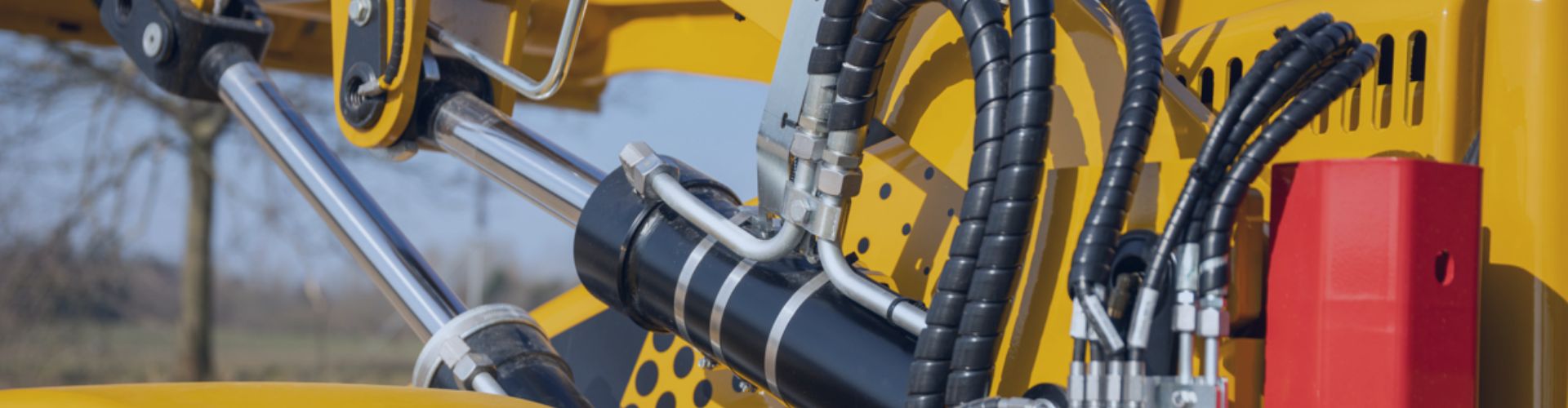
Your production line stops because of a leaking hydraulic fitting. This unexpected failure causes costly downtime, creates safety risks, and raises questions about component reliability in your quality reports.
Premature hydraulic fitting failures are often due to preventable factors. The most common causes are improper installation torque, mismatched components, system vibration, pressure spikes, and chemical corrosion from fluid or environmental incompatibility.
Is Improper Installation the #1 Cause of Failure?
A new assembly fails its pressure test, weeping fluid from the fitting. The components are correct, so your team is left wondering what went wrong during the assembly process.
Yes, improper installation is the leading cause of early fitting failure. Overtightening can crush seals or cause fatigue, while under-tightening allows leaks and invites vibration-induced loosening, both leading to a premature leak path.
The final turn of the wrench is the most critical moment in a fitting’s life. This mechanical action creates the seal and the structural grip. For a quality engineer, this process represents a major variable that must be controlled. Unlike a machined dimension, assembly torque is highly dependent on technician skill and tooling.
The Dangers of Under-Torque
When a fitting is not tightened enough, it fails to achieve the necessary compression for a robust seal. For flared fittings like JIC, the metal-to-metal sealing surfaces do not properly mate. For O-ring boss fittings, the O-ring is not adequately compressed. This leads to two failure modes. First, it creates an immediate slow leak path. Second, it allows the fitting to vibrate and back itself out over time, leading to a catastrophic failure.
The Hidden Damage of Over-Torque
The “tighter is better” mentality is a significant risk. Overtightening a JIC fitting can coin or fracture the flare, creating a stress riser that will crack under pressure pulses. With O-ring fittings, over-torque can extrude the seal into the clearance gap, slicing or damaging it. For tapered threads like NPT, excessive force can crack the female port. This damage is often irreversible and guarantees a future failure, even if it doesn’t leak immediately.
A Controlled Tightening Procedure
A repeatable process is key to quality. We recommend a “Flats From Wrench Resistance” (FFWR) method for flared fittings, as it is less dependent on inconsistent torque wrench readings caused by friction.
Example FFWR Method for JIC Fittings:
- Tighten the nut by hand until snug. This is the zero point.
- Lightly scribe a line on one hex flat of the nut and the fitting body.
- Using a wrench, tighten the nut a specific number of “flats” (a 1/6 turn).
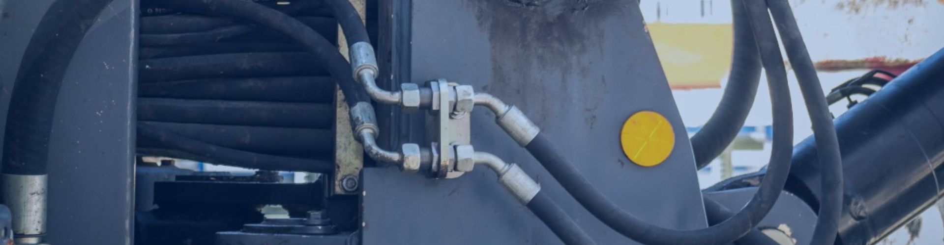
How Does System Vibration Destroy Hydraulic Fittings?
A fitting on a pump outlet repeatedly develops leaks, despite being retightened. The connection seems solid, but it fails within weeks, showing signs of fatigue near the threads.
Vibration attacks fittings by inducing high-cycle fatigue. It causes the fitting to flex minutely, concentrating stress at geometric transition points like thread roots or the base of a flare, eventually leading to microscopic cracks and failure.
From a materials science perspective, steel fittings have a theoretical infinite fatigue life if the stress remains below a certain threshold. However, unsupported hose lengths and harmonic resonance from pumps or engines can create stress levels that far exceed this limit. The fitting then endures millions of cycles until a fatigue crack initiates and propagates.
Understanding Harmonic Resonance
Every hydraulic line has a natural frequency. If the frequency of the pump, engine, or cylinder cycling matches this natural frequency, the amplitude of the vibration can multiply dramatically. This phenomenon, harmonic resonance, creates extreme stress at fixed points, like where a hose connects to a rigid fitting. These forces can snap a fitting or loosen the connection in a very short amount of time. Proper P-clamping of hoses at specific intervals is designed to change the natural frequency and dampen these harmonics.
The Failure Mechanism: High-Cycle Fatigue
Fatigue cracks are the tell-tale sign of vibration failure. They often start at a stress concentration point, like the last thread on a male connector or the bend of a flare. The crack propagates a tiny amount with each pressure cycle or vibration wave. Initially, the fitting may not leak. Eventually, the crack grows large enough to compromise the seal or fracture the fitting entirely. A quality inspection of a failed part should always look for the “beach marks” characteristic of a fatigue fracture surface.
Vibration Mitigation Strategies for Quality Control
| Mitigation Tactic | Description | Quality Checkpoint |
| Proper Clamping | Use cushioned P-clamps to secure hoses to the machine frame. | Verify clamp presence and proper spacing per hose routing guides. |
| Correct Hose Length | Avoid taught hoses that transmit vibration directly. A slight bend absorbs energy. | Ensure a small amount of slack in hose runs without creating a rubbing risk. |
| Use Swivel Fittings | In applications with movement, a live swivel can absorb torsional stress. | Check if the assembly design calls for swivels at points of articulation. |
| Stress Risers | Avoid using multiple adapters; use a single fitting where possible. | Review Bill of Materials (BOM) to minimize stacked fittings. |
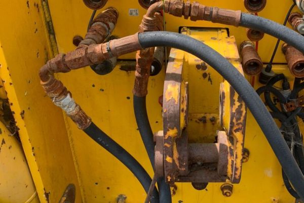
Why Does Material Incompatibility Lead to Leaks?
A fitting made of one material is connected to a port of another. After a few months in a humid environment, the connection begins to corrode and weep fluid.
Material incompatibility causes galvanic corrosion when two dissimilar metals are in contact with an electrolyte (like moisture). It can also cause chemical corrosion if the fitting material is not resistant to the hydraulic fluid itself.

The Threat of Galvanic Corrosion
When two metals with different electrochemical potentials (like stainless steel and carbon steel) are connected, they form a small battery in the presence of moisture. The less noble metal (carbon steel) becomes the anode and sacrificially corrodes at an accelerated rate. This weakens the threads and sealing surfaces, leading to leaks and eventual mechanical failure. The first rule of material selection is to keep metals as close as possible on the galvanic series or use proper isolation.
Chemical Attack from Hydraulic Fluids
Standard hydraulic fluids are generally compatible with steel, stainless steel, and brass. However, aggressive or exotic fluids like Skydrol™ or certain water-glycol mixtures can attack the fitting material or its plating. For example, standard zinc plating can be stripped away by some fluids, exposing the raw carbon steel underneath to corrosion. For a quality BOM, it is crucial to cross-reference the fluid’s chemical compatibility data sheet with all fitting and seal materials.
Common Plating and Material Choices
| Material / Plating | Corrosion Resistance | Common Use Case | Quality Note |
| Zinc Trivalent Cr(III) | Good (96-120 hours salt spray) | Standard, general-purpose industrial | The industry standard for cost and performance. |
| Zinc-Nickel (Zn-Ni) | Excellent (720-1000 hours salt spray) | Marine, outdoor, high-humidity environments | Higher cost, but essential for prolonging life in harsh conditions. |
| 304/316 Stainless Steel | Superior | Food processing, chemical, marine | Best resistance, but can have galling issues if not properly lubricated. |
| Brass | Excellent (for water/air) | Pneumatics, low-pressure water lines | Not suitable for high-pressure hydraulic systems. |
Are Pressure Spikes Silently Killing Your Fittings?
A hydraulic system operates at 2,000 PSI, so you specify fittings rated for 3,000 PSI. Yet, hoses burst and fittings leak, especially near valves and cylinders.
Pressure spikes, or hydraulic shocks, can exceed a fitting’s rated pressure for a millisecond. While the average pressure is safe, these repetitive high-energy impulses fatigue the fitting, causing failures that static pressure ratings do not predict.
This is a subtle but destructive phenomenon. A quality engineer might look at the system schematic and see that the specified components meet the working pressure requirement. However, the system’s dynamic behavior is what causes failures. The rapid closing of a valve or a cylinder bottoming out can generate pressure waves of up to four times the system’s working pressure.
Where Do Pressure Spikes Originate?
Hydraulic shock, also known as water hammer, is generated by any event that rapidly changes the velocity of the hydraulic fluid.
- Valve Actuation: The sudden opening or closing of directional control valves.
- Cylinder Operation: A hydraulic cylinder hitting its end-of-stroke at high speed.
- Pump Ripple: The inherent pressure fluctuations from piston or gear pumps.
- External Loads: An excavator arm hitting an immovable object sends a shockwave back through the system.
Working Pressure vs. Impulse Rating
It is critical to understand the distinction between these two ratings.
- Working Pressure: The maximum continuous static pressure a fitting can safely handle. Quality control usually verifies this.
- Impulse Pressure & Cycle Life: Industry standards like ISO 18752 define impulse test procedures. A fitting is subjected to repeated pressure spikes (often 133% of working pressure) for hundreds of thousands or millions of cycles to test its fatigue life. A fitting with a low impulse rating may fail in a dynamic system even if its working pressure is adequate.
Designing for a Dynamic System
To prevent impulse-related failures, a quality review of the system design should look for mitigation components. Small, inexpensive accumulators can be installed near valves to absorb pressure spikes. Using “soft-shift” valves that ramp up flow can also dramatically reduce shocks. Finally, selecting hydraulic fittings and hoses with a high impulse rating specifically designed for dynamic systems is the most direct solution.
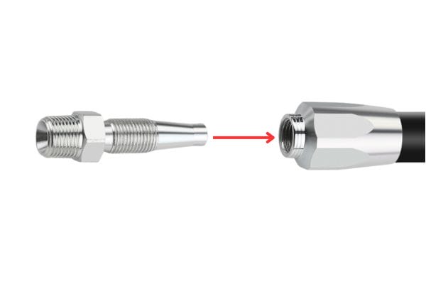
What Happens When You Select the Wrong Fitting?
An assembly is leaking from a brand-new connection. The threads appear to match, but no amount of tightening will seal it. The team is frustrated and production is stopped.
Selecting the wrong fitting, especially one with a mismatched thread type or sealing method, creates an incorrect mechanical interface. Even if the threads engage, the sealing surfaces will not mate properly, guaranteeing a leak.

This seems like a basic error, but it is one of the most common issues we encounter when troubleshooting. The hydraulic world is filled with dozens of thread standards (NPT, JIC, BSPP, BSPT, ORFS, Metric) that are visually similar but mechanically incompatible. A BSPP and NPT fitting might thread together for one or two turns, fooling an assembler into thinking they match.
The Sealing Method is Everything
Fittings achieve a seal in different ways. A mismatch completely defeats this mechanism.
- JIC (37° Flare): Seals on a metal-to-metal cone. Mating it with a 45° flare fitting will seal only on a thin line, which will quickly fail.
- BSPP (Parallel Thread): Seals with a soft bonded washer or O-ring at the base of the threads. The threads only provide clamping force, not the seal.
- NPT (Tapered Thread): Seals by the interference fit of the threads themselves, deformed during tightening (a “thread seal”).
- ORFS (O-Ring Face Seal): Seals via an O-ring compressed against a flat face. This is one of the most leak-resistant designs.
Verifying Thread Types: A Quality Mandate
Relying on visuals is not enough. Quality control must mandate the use of proper identification tools.
- Calipers: To measure the thread’s outside diameter accurately.
- Thread Pitch Gauge: To measure the number of threads per inch or the distance between threads.
- Seat Angle Gauge: To confirm the angle of a flared fitting (e.g., 37° vs. 45°).
Common but Dangerous Mismatches
| Mismatched Pair | Result of Mismatch | How to Identify |
| BSPP Male into NPT Female | Threads will bind after a few turns. No seal is possible. | BSPP is parallel; NPT is tapered. Measure with calipers. |
| JIC (37°) Male into SAE (45°) Female | Seals on a single, thin line of contact. Will leak under pressure/vibration. | Use a seat angle gauge to verify 37° vs. 45°. |
| Metric Male into Imperial (SAE) Female | Very similar diameters can fool assemblers. Cross-threading is guaranteed. | Use a thread pitch gauge. Metric and Imperial pitches are different. |
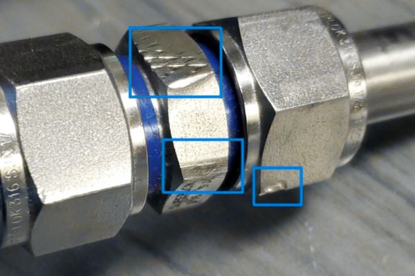
How Do Contamination and Damage Cause Failure?
A fitting that was stored in an open bin is installed and immediately leaks. Upon inspection, you find the O-ring is nicked and there is grit in the threads.
Contamination like dirt or metal shavings can damage delicate sealing surfaces or O-rings during assembly. External damage like nicks or scratches creates stress risers that become initiation points for fatigue cracks under pressure.

Contamination During Assembly
This is a primary concern. A small grain of sand, a metal shaving from cutting a hose, or even a piece of old thread sealant can have major consequences. When the fitting is tightened, this debris is crushed between the sealing surfaces. On a metal-to-metal seal like JIC, it creates a dent and a permanent leak path. On an O-ring or face seal fitting, it can tear or abrade the soft seal, rendering it useless. All components should be inspected and cleaned with a lint-free cloth before assembly.
Stress Risers from External Damage
Hydraulic fittings are often located in exposed areas on mobile equipment. A fitting that is dropped on a concrete floor or hit with a tool can develop a small nick or dent. While it may seem like cosmetic damage, this small imperfection is a stress riser. Under the repeated expansion and contraction from pressure cycles, the stress will concentrate at that point, making it the most likely place for a fatigue crack to form. Quality procedures should include rules for discarding any fitting that shows signs of being dropped or damaged.
Proper Storage and Handling Protocols
To prevent these issues, strong quality controls are needed for component handling.
- Keep in Sealed Packaging: Leave fittings in their original sealed bags and boxes until the moment of use.
- Use Protective Caps: Never remove plastic caps or plugs until you are ready to connect the hose or port.
- Clean Storage Bins: If storing fittings in open bins, ensure the bins are regularly cleaned and covered to prevent dust and debris accumulation.
- Inspect Before Use: Mandate a final visual inspection of threads and sealing surfaces as a standard step in the assembly work instruction.
Conclusion
Preventing premature hydraulic fitting failure relies on controlling key variables. Focus on correct installation, system design to mitigate vibration and pressure spikes, and strict adherence to material selection and cleanliness protocols.
Looking for reliable hydraulic fittings that ensure leak-free performance and long service life? At Topa, we provide precision-engineered fittings with strict quality control and fast delivery to keep your business running smoothly. Contact us today to request a quote and experience the dependable service trusted by customers worldwide.
FAQ
How long should a hydraulic fitting last in normal use?
With proper installation, quality materials, and regular maintenance, a hydraulic fitting can last several years, often matching the lifespan of the hose assembly.
Can I reuse a hydraulic fitting after disassembly?
Most fittings are designed for single use. Reusing them increases the risk of leaks, especially if threads or seals have been deformed during the first installation.
Do hydraulic fittings need lubrication before installation?
Yes. A light application of compatible lubricant on threads or O-rings reduces friction, ensures proper tightening, and helps extend seal life.
How do I choose the right fitting material for my system?
Select based on fluid compatibility, operating pressure, and environmental exposure. For example, stainless steel suits corrosive environments, while carbon steel is common for general use.
Should fittings be pressure-tested separately from the hose?
Ideally yes. Testing fittings and hoses together in an assembly ensures the joint is leak-free under real working pressure.
What maintenance practice helps prevent fitting leaks?
Routine visual inspections for corrosion, cracks, or loose connections, combined with scheduled torque checks, greatly reduce the chance of sudden leaks.