Thread Gauge vs Caliper Which Check Is Reliable

Thread Gauge vs Caliper: Which Check Is Reliable?

A matching caliper reading is only an approximate diameter check; it does not verify the complete thread. Correct identification also depends on thread form, pitch or TPI, straight or tapered construction, effective engagement, and the condition of crests, roots, and flanks. A hydraulic fitting thread gauge supports functional or specification-based inspection that a caliper cannot provide. The best process does not discard the caliper: it uses visual screening, diameter measurement, pitch identification, and the correct plug or ring gauge as complementary checks.

A Caliper Is Valuable for Preliminary Identification

A caliper quickly narrows possible thread sizes and exposes obvious differences. Its proper role is screening and selected dimensional measurement, not final confirmation of a thread standard.

Topa Measure BSP Hydraulic Fittings

What diameter readings can show

On an accessible male thread, a caliper can approximate the major diameter when the contact points and technique are suitable. On an internal thread, it may help screen an opening or minor-diameter-related feature, though access and contact geometry make interpretation more difficult. Measurements should be taken cleanly, at controlled locations, and compared with an approved technical reference.

Repeated readings can also reveal obvious taper or damage, but the instrument’s contact points may sit on thread crests inconsistently. Coating, burrs, wear, incomplete threads, and operator pressure can shift the result enough to confuse two close candidates.

What the caliper cannot establish

A caliper does not directly confirm thread pitch diameter, flank angle, thread profile, root form, or functional fit. It also cannot prove that a connection belongs to a particular standard merely because the displayed diameter resembles a chart value. Internal threads are especially easy to misread because the jaws do not reproduce the designed mating geometry.

Use the result as one piece of evidence:

Similar Diameters Can Hide Different Threads

Thread systems were not designed around caliper readings alone. Different forms or nominal descriptions may produce close measured diameters while differing in pitch, flank geometry, taper, truncation, or sealing method.

Major, minor, and pitch diameter are different

Major diameter relates to the outermost envelope of a thread, while minor diameter relates to the innermost envelope. Pitch diameter is the theoretical diameter where thread and space widths have a defined relationship and strongly affects engagement. A caliper touching crests does not establish the pitch diameter that governs functional fit.

Damage can make the distinction more important. Flattened crests may reduce a caliper reading while the flanks remain oversized, or coating may increase crest diameter without producing acceptable engagement. A “close” number therefore cannot be interpreted independently of the feature measured and the governing specification.

Nominal size is not a complete identity

A nominal connection size may not equal the measured outside diameter. Hydraulic fittings can also use straight or tapered threads and seal at a flare, cone, flat face, O-ring, bonded seal, or the thread itself. A thread match does not automatically establish a sealing match.

When candidates look alike, record the male or female configuration, diameter, pitch or TPI, taper, seat or face, O-ring position, and connection geometry. Final identification comes from the combined evidence, not from the nearest diameter entry.

Thread Form, Pitch, and Taper Need Separate Checks

Each thread characteristic answers a different identification question. Combining them into “size matches” hides the exact point of disagreement.

Pitch and profile

A thread-pitch gauge can help compare spacing against candidate leaves, while suitable optical or profile methods may be needed for controlled form inspection. Pitch in threads per inch and metric pitch are different descriptions; neither should be guessed from a short, dirty, or damaged thread. Align the gauge without forcing it and check enough engagement to expose a false fit.

Pitch agreement still does not prove the complete standard. Similar spacing can occur across different forms, and a pitch leaf is a comparison tool rather than a full acceptance gauge. The specified standard determines the required profile and tolerances.
check connection side

Straight versus tapered construction

A tapered thread changes diameter along its length; a straight thread is intended to maintain its basic cylindrical relationship. Measurements at controlled locations can support identification, but a few caliper readings may be distorted by crest condition, limited thread length, or access. Specified tapered-thread gauges or approved measurement methods provide more meaningful acceptance evidence.

Do not treat thread sealant as a correction for a straight-versus-tapered mismatch. If the connection standard is wrong, sealant cannot restore the intended engagement, strength, or sealing geometry.

GO and NO-GO Gauges Test Defined Limits

GO and NO-GO gauges provide a controlled acceptance check when they are made and maintained for the specified thread. Their result is meaningful only when the gauge type, direction, application procedure, and acceptance criteria match the drawing or standard.

Plug and ring gauge roles

Thread plug gauges are generally used for internal threads, while thread ring gauges are generally used for external threads. The GO member checks whether the applicable thread can accept the maximum-material or functional boundary defined by its specification. The NO-GO member checks the opposite limit under its specified use conditions.

This is a simplified functional distinction, not a universal operating procedure. Gauge engagement, allowable turns, reference position, force, cleanliness, temperature, and other details depend on the thread standard and inspection plan. Inspectors must follow the gauge maker’s and governing specification’s instructions.

ring gauge Topa

What a passing gauge does not prove

A pass supports conformity to the characteristic controlled by that gauge. It does not prove the sealing face, seat angle, O-ring groove, material, pressure rating, hose compatibility, or crimp suitability. It may also fail to describe every individual thread element, so visual condition and other specified measurements still matter.

Gauge Calibration and Traceability Make Results Credible

A thread gauge is not automatically authoritative because it carries a label. Its identity, condition, verification or calibration status, and link to the inspection result determine whether another reviewer can rely on the record.

Control the gauge before use

Confirm that the gauge matches the specified thread, size, and acceptance requirement. Check its identification, status, cleanliness, wear condition, and any environmental or handling requirements in the applicable procedure. Do not use a damaged gauge or one with uncertain status to resolve a borderline result.

Gauge wear can change the effective boundary it represents. Periodic control should follow the organization’s approved measurement system and the gauge maker’s requirements, not an invented universal interval.

Record enough to reproduce the decision

An inspection record should include the part number, lot or sample identity, required thread reference, gauge identifier, inspection date, result, and inspector. If both GO and NO-GO results are required, record them distinctly rather than write only “thread passed.”

When a supplier provides a corresponding inspection record instead of the physical gauge check at receiving, review its method, sample linkage, gauge identity and status, acceptance reference, and batch traceability. A generic statement that threads were checked is weak evidence when it cannot be connected to the delivered lot.

Combine Visual, Caliper, Pitch, and Gauge Checks

The most reliable sequence moves from broad screening to specific verification. This prevents wasted gauge work on an obviously wrong fitting and prevents premature approval from an approximate measurement.
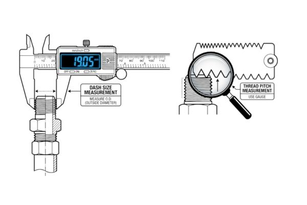
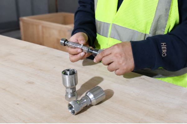
measure Thread size and pitch

A practical inspection sequence

Start by stopping and isolating the hydraulic system, releasing pressure and stored energy, and removing the fitting only under approved equipment procedures. Clean the connection without damaging its crests, flanks, seat, or sealing face. Then document the complete fitting before focusing on the thread.

Use this sequence:

Resolve conflicting evidence

If diameter appears correct but the pitch gauge or functional gauge does not agree, treat the thread as unverified. Do not select a different gauge simply to obtain a pass or force the fitting into a mating port. Review the drawing, standard, measurement technique, cleanliness, damage, and gauge status.

A conflict may show that the candidate thread was misidentified, the part is nonconforming, the gauge is wrong for the requirement, or the method was applied incorrectly. Hold the affected material until the cause and disposition are documented.

Common Thread-Inspection Mistakes

Most errors arise from assigning one tool a broader role than it can support. Clear boundaries between screening, identification, and acceptance keep convenient observations from becoming unsafe conclusions.

Shortcuts to avoid

Common mistakes include choosing the nearest chart size from one caliper reading, ignoring pitch because the fitting starts into a port, and treating partial hand engagement as a functional test. Inspectors may also confuse thread match with sealing compatibility or use a worn, dirty, untraceable gauge.

Avoid these practices:

Consequences of a false match

Mismatched threads can cross-thread, engage weakly, damage the port, or appear to tighten before the intended sealing surfaces meet. The result may include leakage, rework, contamination, lost equipment availability, or an unsafe pressure-containing connection.

Never check a suspected high-pressure leak by hand. Stop the equipment, isolate the system, release stored energy, secure loads, and follow lockout and manufacturer procedures before inspection or replacement.

Thread-Verification Checklist

Before approval, record the fitting and sample identity, male or female configuration, candidate connection standard, accessible diameter, pitch or TPI, straight or tapered construction, thread form, and visible condition. Confirm the seat, sealing face, and O-ring location separately because they are not established by a thread gauge.

For controlled acceptance, identify the specified plug or ring gauge, its status, the procedure and acceptance rule, GO and NO-GO results as applicable, and the lot covered. If any evidence conflicts, preserve the part and records for technical review rather than forcing assembly or inferring equivalence.

Conclusion

Close caliper readings narrow the search, but they do not establish thread form, pitch diameter, taper, functional engagement, or the complete sealing connection. Use a caliper for preliminary measurement, a pitch method for spacing, visual inspection for condition, and the specified plug or ring gauge for the limit or functional check it controls. Gauge identity, status, procedure, sample linkage, and acceptance reference must accompany the result. A passing thread gauge still does not prove seat, seal, material, hose, or crimp compatibility, so keep those verifications separate. Before approving a fitting, prepare the thread observations, controlled measurements, gauge records, sealing details, and application data. That combined evidence gives a hydraulic fitting thread gauge result practical and safe meaning.

Frequently Asked Questions

Is a thread-pitch gauge an acceptance gauge?

Not usually by itself; it primarily supports pitch or TPI identification. Final acceptance may require the specified plug, ring, profile, or other measurement method defined by the governing thread standard.

Can a fitting pass the GO gauge and still be wrong?

Yes, it can still have the wrong sealing face, material, hose side, or other uncontrolled feature. It may also require a NO-GO check and additional characteristics under the applicable inspection plan.

Why should a gauge not be forced?

Forcing can damage the part or gauge and can produce a misleading result. Apply the gauge only with the procedure, cleanliness, alignment, and force conditions specified for that thread.

Are supplier thread-inspection records acceptable?

They may be acceptable when the purchase requirements permit them and the records show method, gauge identity and status, results, samples, and batch linkage. Generic untraceable pass statements are insufficient for controlled verification.

Does matching a thread gauge prove a leak-free connection?

No, the gauge addresses only defined thread characteristics. Leak control also depends on the correct seat or seal, component condition, material, assembly, pressure, temperature, fluid, and installation requirements.

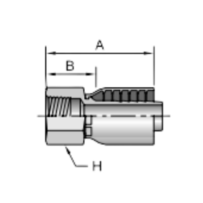
What Should a TP43 One Piece Fitting Dimension Report Include

What Should a TP43 One Piece Fitting Dimension Report Include?

A useful report identifies the exact sample, lists each controlled characteristic against an approved reference, records the method and result, and preserves batch traceability. A part number, product photo, or small group of caliper readings cannot support replacement approval because the connection, seal, hose side, ferrule, and installation geometry may differ independently. A TP43 fitting dimension report should therefore present nominal requirements, tolerances when available, measured values, inspection methods, instrument identities, and pass/fail decisions in a form another reviewer can reproduce. It supports dimensional evaluation, but it does not by itself prove hose compatibility, crimp suitability, pressure capability, or safe interchangeability.

A Few Dimensions Cannot Define a Complete Fitting

Replacement approval fails when a report measures only the easiest visible features. Overall length and thread outside diameter may look close while the thread form, pitch, seat, ferrule, stem profile, or elbow centerline remains wrong.

Dimensions work as a controlled set

Each feature must be evaluated in relation to the fitting configuration. A straight male fitting, a female swivel elbow, and a flange-style connection do not need the same characteristic list. The approved drawing, verified reference sample, or other accepted technical specification should determine which dimensions control fit and function.

The report should also distinguish identification from acceptance. “TP43-style” or a Parker 43 cross-reference can narrow the product family under review, but it does not establish that a replacement is an original Parker product or that every dimension and assembly requirement matches.

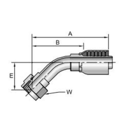
10243 Hydraulic Hose Crimp Fittings Drawing

Photos support, but do not replace, data

Clear photos help reviewers confirm orientation, locate measurement points, see marking, and understand an unusual feature. They cannot reveal a hidden stem profile, prove thread pitch diameter, establish a seat angle accurately, or show whether a reported value was measured from the correct datum.

Use annotated images as navigation aids within the report. Every acceptance decision should still point to a defined characteristic, requirement, method, result, and disposition.

Start With an Unambiguous Report Header

The header determines what the measurements actually represent. Without product and sample identity, even accurate values may be assigned to the wrong size, orientation, revision, or lot.

Product and technical-reference fields

Record the complete product description, internal or supplier part number, cross-reference term when applicable, connection-side size, hose-side size, and straight, 45-degree, or 90-degree configuration. Include the approved drawing or specification number and revision that supplies the nominal requirements. If the technical reference is not yet approved, label its status rather than presenting draft information as final acceptance criteria.

The header should also identify the inspection date, report number, inspection location, and responsible reviewer. A TP43 reference must remain an identification term; it should not be used to imply brand origin or verified interchangeability.

Sample and batch identity

Each sample needs an identifier that connects it to the delivered lot or batch. When several pieces are measured, present results by sample rather than averaging away individual failures. The report should show the order or receiving reference, lot identity, sampled quantity, and any packaging or marking information used to preserve the chain.

Useful header data includes:

Verify the Connection End With Suitable Methods

Connection approval requires more than a nominal name and approximate diameter. Thread form, diameter, pitch or TPI, straight or tapered construction, sex, engagement, and connection geometry must agree with the approved reference.

Thread characteristics and gauges

List each required thread characteristic separately. A caliper may screen an accessible major or minor diameter, but it does not establish pitch diameter, thread form, or functional engagement. Pitch gauges, specified plug or ring gauges, optical methods, or other approved instruments answer different questions and must be selected for the stated thread standard.

The report should identify the gauge type, instrument or gauge number, status, and result. Do not invent universal gauge classes or tolerances; use the requirements defined by the applicable drawing, standard, or inspection plan.

43 series

Connection geometry beyond the thread

Swivel nuts, hex dimensions, flange faces, pilots, counterbores, undercuts, and other connection details may affect assembly or clearance. Report only those relevant to the specific fitting, but do not omit a feature simply because it is harder to measure. If a dedicated fixture or profile method is required, identify that need rather than substituting an approximate caliper value.

A functional trial with an unknown port should not replace controlled thread verification. Forcing mismatched components can damage threads and create false confidence from partial engagement.

Document the Sealing Face and Seat

Two connections can have similar threads yet seal by different mechanisms. The report must identify the sealing feature independently from the thread so a matching diameter does not conceal an incompatible seat, face, cone, or O-ring arrangement.

Sealing geometry and condition

Depending on the configuration, relevant characteristics may include seat or cone geometry, flat-face position, sealing diameter, groove location, pilot relationship, and the presence of an O-ring or bonded sealing element. The approved reference determines the actual list and measurement method. Do not infer or invent a seat angle because the fitting resembles a familiar standard.

Visual condition should be reported separately from dimensional conformity. Scratches, dents, burrs, coating buildup, damaged grooves, or contamination may compromise sealing even when a major dimension passes.

Make the measurement location clear

Seat and face results are difficult to interpret when the datum or contact points are omitted. An annotated drawing view or photo can show where the characteristic begins and ends. For angular or profile requirements, identify the instrument and method that can resolve the feature reliably.

Thread sealant is not a corrective action for the wrong sealing face, seat, or connection standard. A discrepancy requires containment and technical review, not an assembly workaround.

Capture the Hose Side, Stem, and Ferrule

Dimensional similarity at the port does not prove that the replacement belongs with the intended hose. The hose-side report must address the stem and ferrule characteristics controlled by the fitting series and approved assembly data.

Stem and nipple characteristics

Record the hose-side nominal size and the dimensions or profiles that the approved technical reference identifies as critical. These may involve insertion-related geometry, stem sections, retention features, transitions, or other configuration-specific details. The exact list must come from verified data rather than an assumed profile shared by all one-piece fittings.

Do not present one insertion depth, skive rule, or crimp diameter as universally valid. The current hose manufacturer, hose series, construction, fitting series, ferrule design, crimp equipment, die, and crimp specification must be confirmed for assembly.

hydraulic fitting11343 NPT

Ferrule identity and condition

The report should state whether the ferrule is preassembled or retained as expected and identify the characteristics being checked. Note visible damage, deformation, incorrect retention, or a mismatch with the approved sample or drawing. A ferrule that appears to fit over the stem is not proof that it will compress the intended hose correctly.

Where ferrule dimensions are required, show their nominal requirement, tolerance if available, result, and method like any other controlled characteristic. Do not reduce the report to “ferrule present.”

Include Overall Geometry and Installation Dimensions

The fitting can pass thread and hose-side checks but still fail in the machine because its body geometry interferes with adjacent components. Overall length, elbow centerline, drop, orientation, and wrench-access features should be included when they affect installation.

Straight and elbow measurements

For straight fittings, the controlling dimensions may use sealing, shoulder, body, or hose-side datums. Elbows require clearer definitions because measuring along an outside curve is not equivalent to locating the connection and hose centerlines. Report the angle and centerline-related dimensions specified by the drawing rather than a vague “same overall size” statement.

Use a fixture, height gauge, optical system, or other suitable method when caliper access does not provide a repeatable result. The method should reflect the required tolerance and geometry, not merely the tools available on the inspection bench.

Clearance and assembly envelope

Swivel-nut diameter, hex size, ferrule envelope, bend orientation, and rotation range can determine whether tools and neighboring parts have enough room. These may be dimensional or functional observations depending on the approved plan. Record them explicitly when the replacement application has restricted space.

Installation photos and equipment measurements can help define the required envelope, but they do not replace fitting-level controls. Keep the application requirement linked to the characteristic that addresses it.

Present Requirements, Methods, and Results Together

A report becomes actionable when each row explains what was required and how the decision was reached. Lists of unlabeled numbers force the reviewer to guess which value is nominal, measured, or acceptable.

Practical report fields

Nominal dimensions describe intended targets; tolerances define permitted variation; measured results state what the identified sample produced. A pass/fail decision compares the result with the approved rule. None of these fields should be substituted for another.

Preserve raw results and measurement status

Do not report only an average when individual values determine acceptance. Identify out-of-range, not-measured, not-applicable, or pending characteristics clearly. Rounding should not hide a borderline result, and units should remain consistent with the technical reference.

The instrument record should show enough information to confirm that the equipment was suitable and within its required status at the time of inspection. If measurement uncertainty or method capability affects the decision, escalate it under the approved quality process rather than declaring a convenient pass.

Control Traceability, Exceptions, and Approval

The completed report should connect results to the sample and preserve every exception. Dimensional evidence without disposition leaves the replacement decision unresolved.

Batch chain and exception records

Link sample IDs to the lot, carton, order line, and receiving record. If parts are separated after inspection, maintain the accepted or held identity in storage. Mixed batches should not inherit a result from a sample that cannot be traced to them.

For every deviation, record:

Approval boundaries

Dimensional approval means only that the stated characteristics met the stated dimensional criteria for the identified samples or lot under the plan. It does not establish material grade, surface-treatment performance, pressure rating, fluid or temperature suitability, or hose-and-crimp compatibility unless separate verified evidence covers those areas.

The final replacement decision should combine the dimension report with material records, thread and sealing verification, hose assembly data, application requirements, and controlled validation where applicable. Safety-critical assemblies should never be approved from an unverified cross-reference, a single attractive sample, or dimensional similarity alone.

43 series Hydraulic Crimp Fitting

Dimension-report checklist

Before review, confirm the product description, size combination, orientation, reference drawing and revision, sample IDs, lot number, and order link. For the relevant configuration, include thread form and verification, sealing geometry and condition, hose-side stem and ferrule characteristics, key body dimensions, overall or centerline geometry, and installation-clearance features.

Each characteristic needs a nominal requirement, tolerance or acceptance rule when available, individual result, unit, method, instrument identity, and pass/fail status. Attach annotated photos only as support. Record missing data and deviations openly, then combine the dimensional report with material, hose, crimp, pressure, temperature, fluid, and application evidence before approving a replacement.

Conclusion

A defensible dimension report is a traceable comparison, not a collection of caliper readings. Identify the exact fitting, technical reference, samples, and batch; then report connection, sealing, hose-side, ferrule, body, and installation characteristics relevant to that configuration. Keep nominal requirements, tolerances, measured values, methods, and pass/fail decisions in separate fields so another reviewer can follow the logic. Photos clarify locations but cannot replace gauges or measured data, and dimensional acceptance cannot prove material, crimp, pressure, or application suitability. Before approving a TP43-style replacement, assemble the report with verified hose and fitting data, material records, application conditions, and documented exception decisions. Those combined records give a TP43 fitting dimension report its practical approval value.

Frequently Asked Questions

Can one approved sample define every future batch?

No, one sample demonstrates only the characteristics checked on that identified sample. Repeat orders still need agreed batch traceability and inspection controls to support continued conformity.

Should the report include every possible fitting dimension?

No, it should include every characteristic required by the approved reference and risk plan for that configuration. Adding uncontrolled measurements can confuse review without improving the decision.

Is a caliper enough for thread verification?

No, a caliper can support preliminary diameter checks but cannot fully verify thread form, pitch diameter, taper, or functional fit. Use the specified gauges and methods for the required thread standard.

Can dimensional results prove crimp compatibility?

No, dimensions alone cannot prove a safe hose-and-crimp combination. Current data for the exact hose, fitting, ferrule, machine, die, and crimp specification remains necessary.

How should a missing tolerance be reported?

It should be marked as unresolved rather than assigned an invented limit. Obtain an approved drawing, specification, or technical decision before issuing a final pass/fail result for that characteristic.

How to Find Hard-to-Source One Piece Fittings Faster

How to Find Hard-to-Source One Piece Fittings Faster

Hard-to-source one piece fittings are sourced faster when the request defines the complete connection, hose side, geometry, material, application, and required quantity. An old part number or unclear photograph may narrow a search, but it cannot prove thread standard, sealing method, fitting series, hose compatibility, or installation clearance. Uncommon, obsolete, and regional fittings require disciplined identification before any candidate is approved.

Why Some Fittings Are Difficult to Source

Difficulty usually comes from incomplete identity, limited current production, regional connection systems, or a special geometry rather than from the word “obsolete” alone. The first task is to establish what the existing fitting actually is.

Standard crimp Fitting

Legacy descriptions lose technical meaning

Old labels may show only a brand code, customer nickname, or shortened size. Part numbers can be revised, superseded, reused in internal systems, or separated from their original catalog. A code remains useful evidence, but it should be connected to a verified drawing, catalog record, equipment documentation, or measured sample before it controls a replacement.

Search records should preserve failed leads as well as possible matches. Note which catalog family, thread assumption, or cross-reference was checked and why it was rejected. This prevents another reviewer from repeating the same path and helps reveal the missing fact that separates candidates. Keep the notes factual: “pitch not confirmed” or “centerline exceeds available space” is more useful than “looks wrong.”

Uncommon combinations reduce obvious options

A fitting can combine a familiar thread with an uncommon hose dash, reducer arrangement, long drop, special angle, restricted envelope, material, or finish. One-piece construction means the stem or body and ferrule are preassembled, attached, or retained together; the exact design varies by series. That arrangement does not make a visually similar hose tail compatible with the existing hose or crimp process.

Complete Identification Information Reduces Delay

A structured request prevents repeated questions and eliminates candidates that could never fit. Separate preliminary identity evidence from final technical approval.

Define the port connection

Record male or female connection, measured outside or inside diameter, pitch or TPI, straight or tapered thread, seat angle where relevant, sealing face, O-ring location, and sealing method. Do not identify NPT, NPTF, BSPP, BSPT, JIC, SAE, ORFS, ORB, Metric, DIN, JIS, or flange connections from appearance alone. Photos support screening, but final identification may require suitable thread gauges, measurement, and standards-based comparison.

Define the hose side and geometry

Record hose manufacturer or compatible specification, hose series, construction, hose ID, dash size, reinforcement, existing fitting series, and ferrule relationship. Include straight, 45-degree, or 90-degree form, orientation, drop, overall envelope, and any clearance-critical dimensions. The same port end can be paired with different hose tails, and the same hose dash does not prove compatibility.

Prepare these request items:

Use Old Part Numbers as Leads, Not Final Proof

Cross-reference searches can save time, but a suggested match must be checked against technical requirements. A shared number fragment or catalog description does not establish interchangeability.

Verify the source and revision

Ask where the number came from: product marking, package, invoice, machine parts list, distributor database, or handwritten record. Record any manufacturer name and approximate document date without assuming the information remains current. If an archived catalog or drawing is available, compare its revision and full suffixes because those may encode material, angle, or size.

Build a comparison record

For each candidate, compare thread and seal, port dash, hose dash, stem and ferrule design, fitting series, configuration, critical dimensions, material, finish, and application data. Mark missing evidence explicitly. A candidate can be “possible for further review” without being “approved for use.” Never invent a cross-reference to close an urgent request.

Use a comparison sheet with one requirement per row and separate columns for the original evidence, candidate evidence, and review status. This makes important technical gaps visible early and prevents an attractive catalog description from outweighing an unverified thread or hose side. Record who supplied each document and its revision. When two sources conflict, pause the decision and resolve the discrepancy rather than selecting the value that makes the candidate fit.

Photos, Drawings, and Samples Have Different Roles

Use the least ambiguous evidence available, but understand what each source can and cannot prove. Combining them is often more effective than asking for more photographs of the same uncertain feature.

Capture useful photographs

Photograph the complete fitting from several orientations with markings readable. Add close views of the male or female thread, seat or sealing face, O-ring location, ferrule, and hose tail. Include a scale only as a visual aid; perspective and lens distortion make photos unsuitable for final measurement. Clean only enough to reveal features without damaging evidence.

Male Hydraulic Crimp Fitting

Measure or submit a sample safely

Before removing a fitting, stop equipment, isolate the hydraulic system, release pressure and stored energy, secure raised loads, and follow lockout and manufacturer procedures. Never check a suspected injection leak by hand. A physical sample should be tagged with its machine position, hose information, orientation, and known part reference. Note damage, wear, corrosion, or deformation so it is not mistaken for original geometry.

Drawings are especially valuable for critical lengths, centerlines, angles, thread callouts, seal features, and installation envelope. A hand sketch can organize questions, but it is not an approved technical drawing unless its dimensions and authority are verified.

Measurement planning matters because worn threads and damaged sealing faces can mislead the review. Clean the part without altering surfaces, identify where measurements are taken, and repeat questionable readings with suitable equipment. Where the old part is installed, record accessible dimensions and orientation before removal. After removal, compare those notes with the free part so hose twist or installation load does not distort the assumed geometry.

If a sample must be sent for inspection, protect threads, sealing surfaces, and the ferrule from shipping damage. Include a reference sheet linking it to the inquiry while removing customer-identifying information not needed for technical review. Photograph its condition before dispatch and state whether it is worn, damaged, or known to have leaked.

Regional Standards Narrow the Search Carefully

Destination country, equipment origin, and application sector can suggest likely connection families. They should guide the search order, not decide the answer.

Equipment fleets mix standards

Imported machines, replacement subsystems, attachments, previous repairs, and local modifications can introduce different thread systems on one site. A machine built in one region may use components sourced globally. Never assume all ports follow the country’s most common standard.

Confirm measured features

Use equipment origin to choose likely gauge and reference checks, then confirm diameter, pitch or TPI, taper, gender, seat, seal, and engagement requirements. Similar tapered threads must not be forced together. Thread sealant cannot correct the wrong thread form, pitch, taper, damaged seal face, or cross-threading.

Compare Replacement Options as Complete Assemblies

Identifying a connection is only one part of approval. The candidate must also suit the hose, crimp process, application, and installation space.

Verify hose and crimp compatibility

Require current data for the specific hose manufacturer or compatible specification, hose series, construction, size, fitting series, ferrule, crimp machine, die, preparation, insertion, and final crimp. Do not infer a diameter, die, skive requirement, or pressure rating from another assembly. Pressure suitability is limited by the lowest-rated component and affected by fluid, temperature, impulse, routing, condition, and installation.

Review geometry and environment

Compare orientation, centerline, wrench clearance, bend near the fitting, adjacent components, and hose routing. Material and finish decisions may depend on fluid compatibility, corrosion, temperature, outdoor exposure, washdown, chemical contact, and equipment requirements. No material or surface treatment is universally best.

Use a staged decision: identify, compare documents, inspect a sample where appropriate, verify the assembly procedure, and approve only after relevant evidence is complete. High-risk use may require additional validation defined by the responsible manufacturer or engineering authority.

Commercial availability should be assessed only after the technical boundary is clear. Determine whether the candidate is a current standard item, a configurable combination, a special manufacture, or an unsupported proposal. Confirm what documentation will accompany it and whether repeat identity can be maintained. A low initial quantity may support inspection, but one accepted sample does not approve later batches or other sizes. Record the exact SKU, revision, evidence, and validation scope so a successful search does not become a vague cross-reference in the next order.

Avoid Common Sourcing Mistakes

Most delay is created by starting with a vague request, chasing many visual matches, and discovering late that the hose side or geometry was never recorded.

Do not confuse speed with approval

Avoid sending only one photograph, using “same as” without a reference, treating nominal size as a thread measurement, or requesting a substitute before identifying the seal. Do not approve by price or availability when technical evidence is incomplete. If no direct replacement exists, the safe outcome may be redesign review, an adapter solution approved for the application, or continued search—not a forced near-match.

Use this final request checklist:

Conclusion

Faster sourcing begins by replacing a vague search with a complete technical record. Use an old part number to locate evidence, but verify the connection, sealing method, port dash, hose dash, fitting series, geometry, material, finish, and application independently. Combine clear photos with suitable measurements, drawings, or a safely removed sample, and use equipment origin only to prioritize likely standards. Compare candidates as complete hose-assembly and installation solutions, using current manufacturer data for hose, ferrule, equipment, die, and crimp requirements. When evidence is missing, keep the candidate in review instead of calling it interchangeable. This disciplined approach reduces delay and makes hard-to-find one-piece fittings safer to identify, compare, and approve.

Frequently Asked Questions

Can a clear photo identify an obsolete fitting?

No, it can narrow possible forms and show visible markings or seals. Final identification usually needs thread measurements, sealing details, hose information, and critical dimensions.

Is an old branded part number enough for a replacement?

No, the number may be incomplete, obsolete, or revision-specific. Verify it against controlled technical data and the actual application.

Does the destination country confirm the thread standard?

No, it only suggests likely standards. Imported equipment, attachments, and prior repairs can mix connection systems on the same machine.

Can an adapter solve every unavailable fitting problem?

No, an adapter changes geometry and adds interfaces that may affect clearance, sealing, pressure suitability, and routing. It requires application-specific technical approval.

What if no direct replacement can be verified?

Do not use a close-looking substitute. Keep the request open for further verified technical evidence or obtain an authorized redesign or repair decision based on the complete system requirements.

How to Pick One-Piece Fittings Without Warehouse Errors

How to Pick One-Piece Fittings Without Warehouse Errors

Reliable one-piece fitting warehouse picking depends on controlled product identity, not visual recognition. Similar fittings can differ in thread standard, sealing feature, port dash, hose dash, fitting series, angle, material, or finish while sharing nearly the same silhouette. If descriptions, bins, inner labels, cartons, and picking records do not use the same fields, a correct order can receive the wrong component. The practical solution is to maintain one SKU identity from receipt through final packing, separate easily confused attributes, and verify exceptions before substitution.

Similar Fittings Are Easy to Mispick

One-piece construction keeps the stem or body and ferrule preassembled, attached, or retained together, which can reduce separate ferrule selection. It does not make different series or connections visually distinguishable and does not prove hose compatibility.

order of one piece Fitting

Appearance hides functional differences

Two fittings may share body shape and nominal size while using different thread form, pitch or TPI, taper, seat, sealing face, or O-ring location. Straight, 45-degree, and 90-degree configurations can also have different installation envelopes even when both ends appear similar. Color and finish appearance are weak identifiers because lighting, surface treatment, storage condition, and batches can change how parts look.

Port dash and hose dash create another common trap. They refer to different ends and may be unequal on a reducer. A label showing only “-8” leaves staff guessing which side it describes. The fitting series must also remain visible because identical hose dash values do not establish the same stem, ferrule, hose construction, or crimp data.

Mixed stock multiplies ambiguity

Broken packages, returns, loose pieces, and overflow stock can introduce a different SKU or batch into a bin. Once mixed, counting accuracy does not restore identity. Segregate uncertain parts and verify connection, dimensions, hose side, markings, and traceability before returning them to usable stock. Never place a close-looking fitting into a bin merely because its expected location is nearby.

Receiving and replenishment can create the same risk before an order is picked. Verify the inbound carton and inner package against the purchase line before filling a forward-pick location, and do not top up a bin while questionable pieces remain inside. When stock from different batches may share a location, define how lot identity will be preserved through partial picks. A location count proves quantity only; it does not prove that every piece belongs to the expected SKU or traceable batch.

Picking Records Need Complete SKU Fields

A picking list should show the few technical fields that distinguish adjacent SKUs. A part number remains essential, but it is safer when paired with a controlled description rather than treated as a code workers must memorize.

This also allows a second checker to verify the selection without relying on the first picker’s assumptions or product memory.

Define one unambiguous identity

The master item should include connection standard, gender, port dash, hose dash, fitting series, configuration, material, finish, and revision where applicable. Add seat or sealing method when similar connections could be confused. Customer or legacy references may be searchable aliases, but they should resolve to one controlled internal identity instead of replacing it.

Avoid free-text abbreviations that change between sales, purchasing, and warehouse systems. If one record uses “size 8 female elbow” and another uses a part number with no decoded fields, the picker cannot independently check the requested part. Consistent field order also makes differences easier to notice.

Design the picking line for verification

Useful picking fields include:

Do not overload the line with unrelated data. The goal is to expose high-confusion attributes at the decision point. If a required technical field is unknown, stop the order line for clarification rather than using the most similar available SKU.

Bin, Inner-Pack, and Carton Labels Must Agree

Every physical level should point to the same controlled item. Label alignment prevents a correct inner pack from being placed in a carton bearing another SKU and helps detect product that entered the wrong bin.

Use a common label source

Bin labels, inner labels, carton labels, and packing documents should be generated from or checked against the same master data. Human-readable text should accompany a barcode so staff can verify identity when scanning fails or the code is damaged. A barcode does not guarantee accuracy if it encodes the wrong SKU or is attached to the wrong product.

Control relabeling and damaged packs

Relabeling should require confirmation of the physical part, original identity, batch, and reason. Printing a replacement from the expected bin record can perpetuate an earlier mix. Keep damaged or incomplete packs in a controlled location until verification is finished. When repacking is allowed, preserve required quantity, SKU, and batch information.

Display Port Dash and Hose Dash Separately

Dash ambiguity deserves its own control because it can survive several reviews. Staff may recognize the connection correctly but still select the wrong hose tail.

1B143 hydraulic hose crimp fittings Drawing Topa

Avoid one generic size field

Use explicit names such as Port Dash and Hose Dash, and keep their order consistent on screens, labels, and documents. If the connection standard uses a nominal pipe size or another designation, do not convert it casually into a hose dash. Record the applicable naming system accurately.

For reducers and uncommon combinations, highlight both values without relying on color alone. Color may help scanning but must not carry the only meaning. Workers with monochrome documents, faded labels, or visual limitations still need readable text.

Verify the complete assembly requirement

Correct dash display does not approve a hose assembly. Suitability depends on hose manufacturer or compatible specification, hose series, construction, size, fitting series, ferrule, crimp equipment, dies, and current crimp instructions. Never substitute a fitting because port and hose dash match while the series or assembly data differs.

Scanning Supports but Does Not Replace Picking Judgment

Barcode or scan verification can compare the requested SKU with the picked label and location. Its value depends on accurate master data, correctly labeled stock, and deliberate exception handling.

Scan independent points

A practical workflow can scan the picking line, bin or product label, and pack destination. The comparison should reject mismatched codes and prevent silent overrides. Scanning the bin label twice does not verify the product inside it, so use the most independent product or inner-pack identity available.

When quantities are split, returns are processed, or stock is moved, update the inventory location and batch relationship through the controlled transaction. Unrecorded movement creates correct scans at incorrect physical locations.

Cycle counting should include identity checks where confusion risk is high. A count that merely confirms the system quantity can miss a bin holding the correct total of two different fittings. Compare the bin label, representative product or inner-pack labels, batch information, and master description. Escalate damaged labels and unexpected loose parts rather than assigning them to the location just to close the count.

Control exceptions visibly

Do not invent system capabilities or assume software blocks every error. Document what happens when a barcode is missing, duplicated, unreadable, or inconsistent with the part. Manual approval should record the verifier, evidence, corrected identity, and disposition. An unavailable ordered SKU is not authorization to scan or ship a similar alternative.

Final Verification Before Packing

The final check should compare the physical item and its inner label with the order line and carton label. It is most useful when independent from the original pick and focused on attributes likely to be confused.

Verify product, quantity, and traceability

Read the controlled part number and compare connection, both dash values, series, configuration, material or finish, quantity, and batch. Inspect packaging for mixed labels or loose pieces. If the product lacks usable marking, verify its identity through approved dimensions, gauges, drawings, or receiving records rather than visual confidence.

Final checks should not become an excuse for weak upstream control. Record mispicks by cause—master data, location, mixed bin, label, scan exception, or human selection—so the process step can be corrected.

For orders with several similar lines, check each line independently and keep verified groups separated until packing is complete. Do not rely on a correct total carton quantity. A swap between two lines can preserve the total while giving both lines the wrong parts. Controlled staging positions or clearly identified temporary containers can support separation without requiring one universal warehouse layout.

Protect safety when an error is found

Do not ship or install a similar-looking fitting to avoid delay. A mispick can create thread damage, wrong sealing contact, installation interference, incompatible hose assembly, leakage, or pull-off. If a suspected error is found after installation, stop equipment, isolate the system, release pressure and stored energy, secure loads, and follow applicable manufacturer and lockout procedures before inspection. Never check a high-pressure leak by hand.

Prevent Recurrence With Warehouse Records

Picking data should improve locations, labels, and master descriptions. The objective is not to blame the last handler but to remove the ambiguity that allowed the error.

Review error patterns

Repeated confusion between the same two SKUs may justify clearer descriptions, physical separation, location warnings, or an extra scan comparison. Repeated dash errors suggest the display order is unclear. Repeated mixed batches may point to repacking, returns, or replenishment practices. Select the control that addresses the observed entry point.

Use a neutral warehouse checklist:

Conclusion

Warehouse accuracy starts with one controlled product identity carried through every record and package. Make connection standard, port dash, hose dash, fitting series, configuration, material, finish, and batch visible wherever they distinguish similar parts. Keep uncertain, loose, returned, or damaged stock out of normal bins until identity is restored. Scanning can strengthen comparison, but only accurate master data, correct physical labels, and controlled exceptions make it trustworthy. The final pack check should compare the product and inner pack with the order and carton, then feed any error back to its source. A disciplined one-piece fitting warehouse picking process reduces wrong shipments without relying on appearance, memory, or unsafe substitution.

Frequently Asked Questions

Can fittings with the same color be stored as one SKU?

No, color does not confirm thread, seal, dash combination, series, material, or finish specification. Each controlled technical identity needs appropriate segregation.

Should a barcode contain every technical detail?

Not necessarily, but it should resolve reliably to the controlled SKU. Important human-readable fields should remain visible so staff can detect mislabeled or inconsistent stock.

Is scanning the bin enough to verify a pick?

No, a correct bin label cannot prove that the contents are correct. Compare an independent product or inner-pack identity with the requested order line whenever practical.

How should loose fittings be handled?

Segregate them until identity and traceability are re-established through approved records, measurements, gauges, or markings. Do not return them to a bin based only on shape.

Can matching port and hose dash confirm compatibility?

No, fitting series, hose construction, ferrule design, equipment, dies, and current crimp data also control assembly suitability. Matching dash values are only part of identification.

Contact Topa

Save 30% on maintenance costs with our easy-install hydraulic fittings. Contact Now!