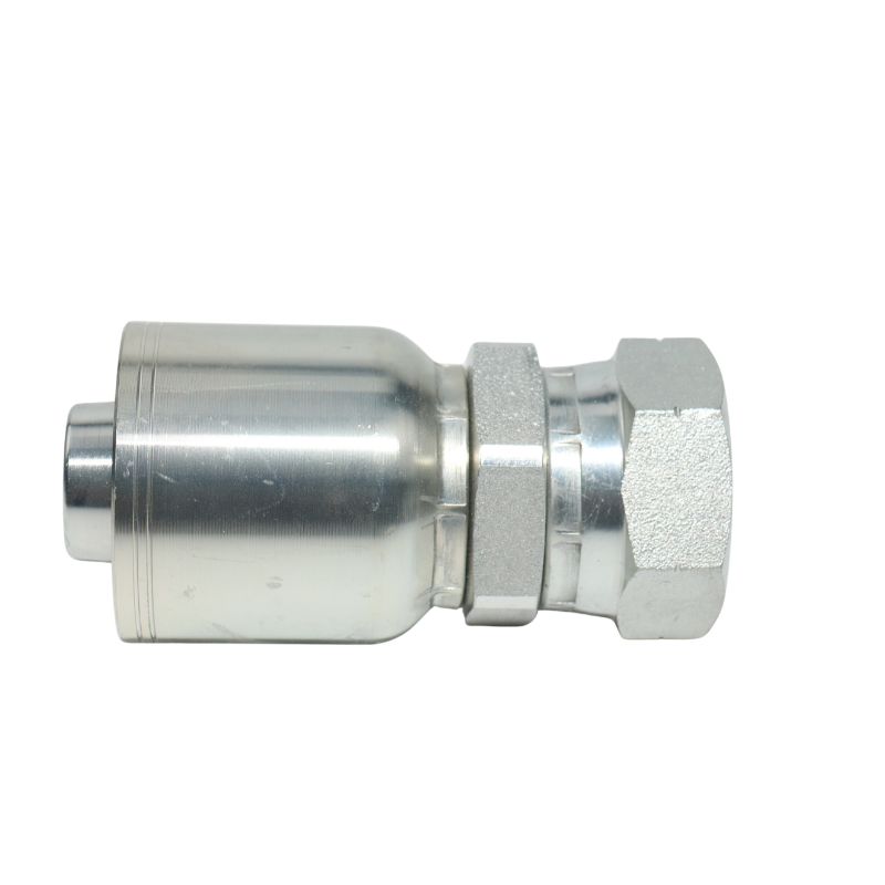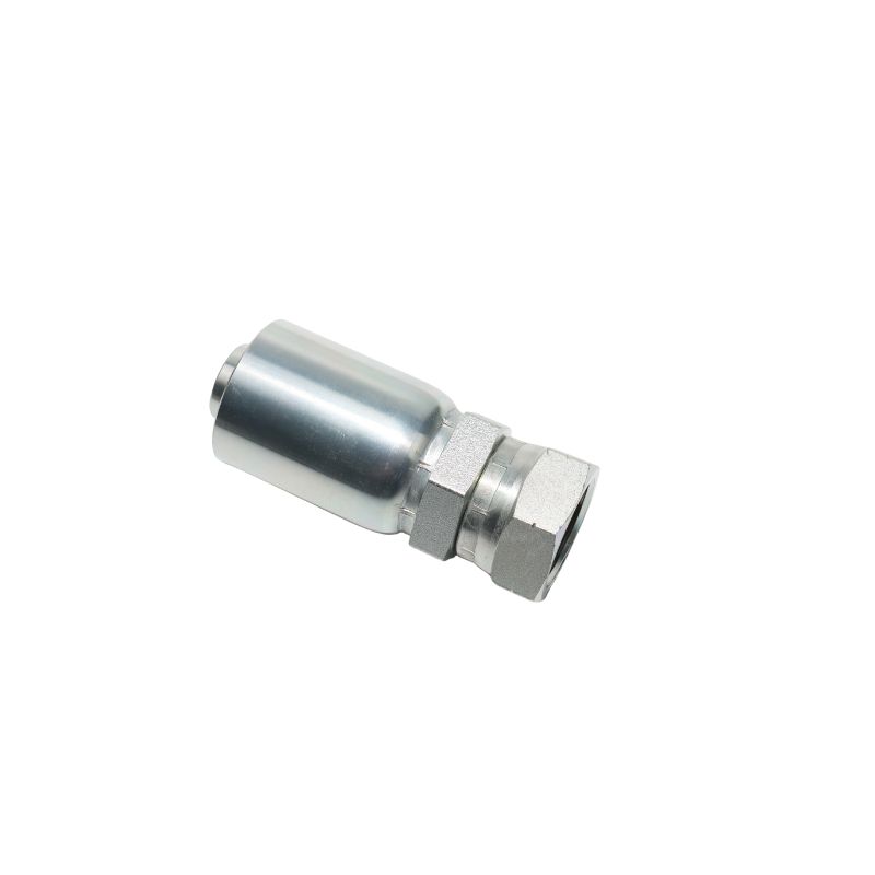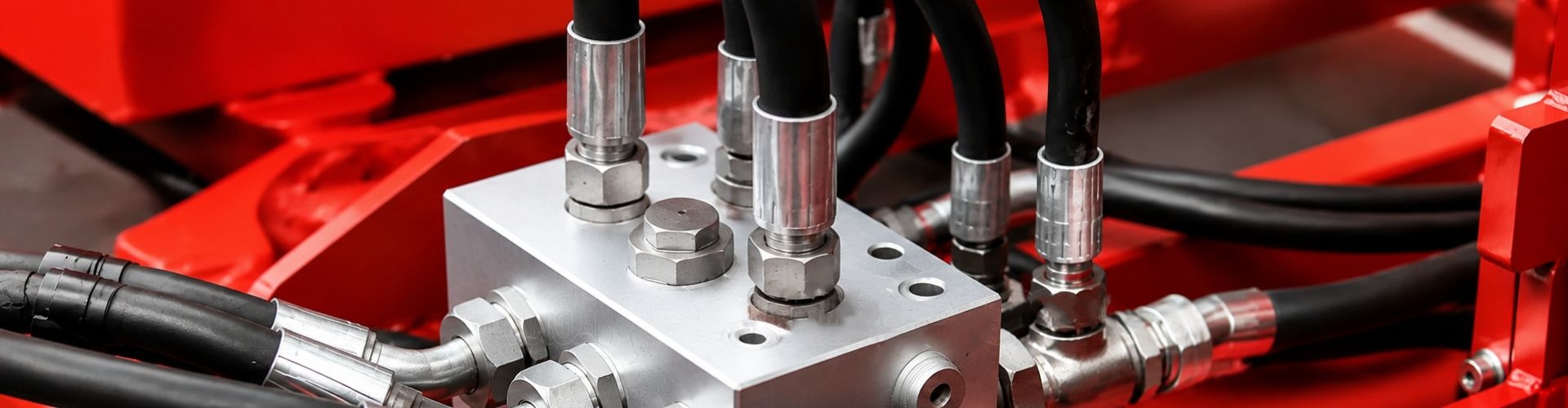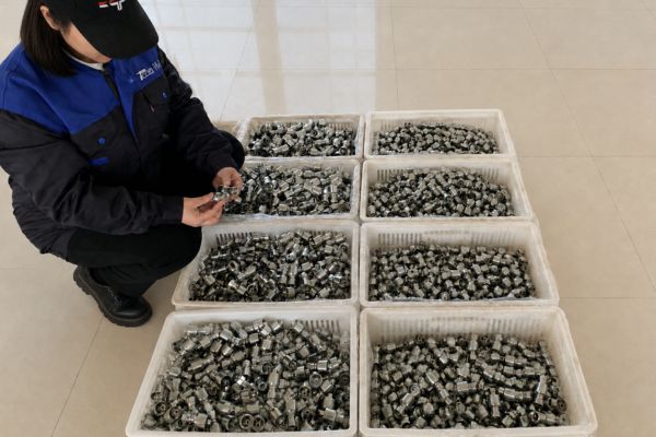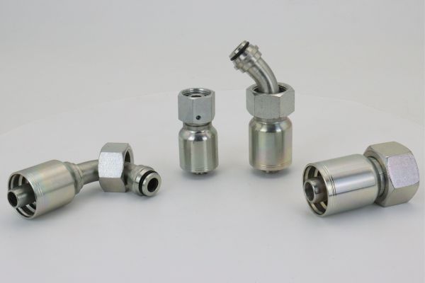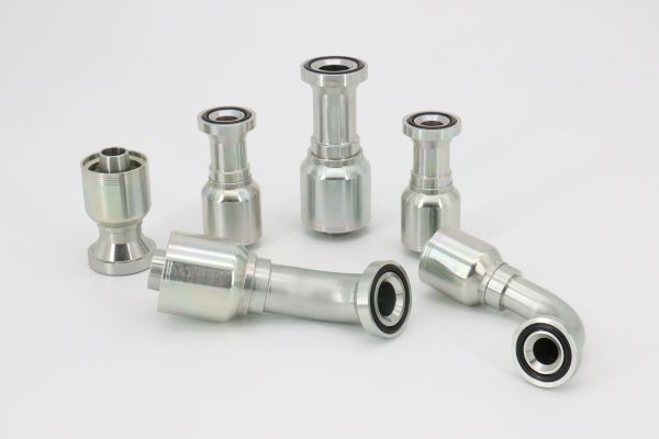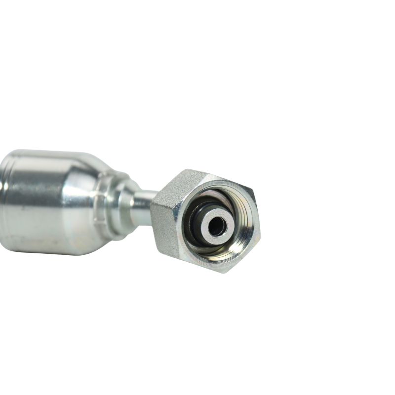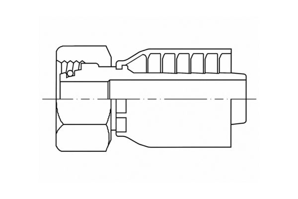
What Pre-Shipment One Piece Fitting Photos Should You Request

What Pre-Shipment One Piece Fitting Photos Should You Request?

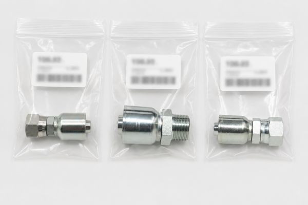
Useful pre-shipment one piece fitting photos must identify each order line and show the product, connection details, hose end, protection, labels, packaging, and shipment context clearly enough for comparison. General images of cartons or mixed fittings cannot confirm which TP43-style model, quantity, label, or protective method is represented. Photos can reveal obvious mismatches and unanswered questions before ocean shipment, but they cannot prove dimensions, material, pressure capability, hose compatibility, or complete conformity.

General Shipment Photos Leave the Main Questions Unanswered

A wide warehouse image may show that goods exist, yet it rarely proves that the correct SKUs are separated, protected, labeled, and ready for the specified order. The value of a photo comes from traceable content, not visual volume.
clear label

Context without identity creates ambiguity

Rows of cartons do not reveal the connection standard, fitting angle, port dash, hose dash, sealing face, or model inside. A pile of similar fittings may include several order lines whose bodies differ only at the thread, seat, O-ring, nut, or hose stem. If the viewer cannot map the image to the purchase order, the photo provides atmosphere rather than verification.

Mixed parts create additional uncertainty. A correct component in the foreground can distract from an incorrect label or different model behind it, and the buyer cannot tell whether every visible piece belongs to one SKU. Separate photo groups should preserve identity from the individual fitting through inner packaging, carton, and shipment unit.

Photos answer visual questions only

Images can support checks of overall structure, angle, visible connection features, marking, cap presence, label wording, SKU separation, package condition, and some quantity references. They cannot establish an exact dimension without a controlled measurement record, and a ruler placed loosely beside a part is not equivalent to a dimensional report. Lighting and perspective can also distort color, proportions, and surface appearance.

A photograph cannot identify material grade, internal cleanliness, pressure rating, or compatibility with a particular hose and crimp system. Continue using approved drawings, inspection reports, material evidence, product specifications, and application data for those characteristics. The photo request should complement those controls, not compete with them.

Photograph the Whole Product From Useful Angles

Each SKU needs enough overall views to show its structure and orientation. There is no universal fixed number because a straight fitting, elbow, female swivel, flange, and complex multi-angle component expose different decision points.

Establish an identifiable overview

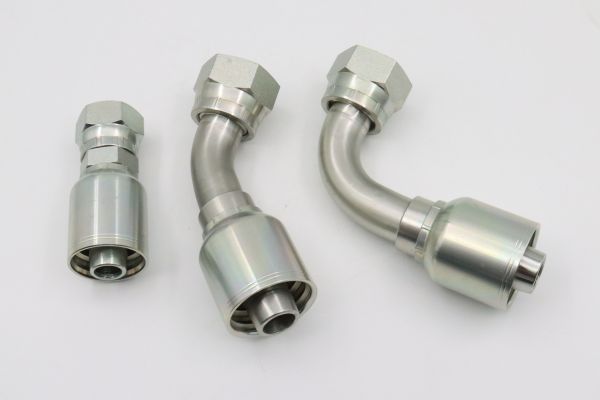
Begin the photo group with the complete fitting beside its SKU or order-line identifier. Show the connection end, hose end, body or stem, ferrule, nut if present, and general orientation. For a 45-degree or 90-degree fitting, include a view that makes the angle and relative direction clear instead of relying on a top view that visually flattens the bend.

Use a clean, contrasting background and adequate focus. The part should fill enough of the frame to support review without cropping either end. When several pieces demonstrate batch appearance, arrange only like-for-like units and keep the model label visible in the same frame or an immediately linked image.

Add views that expose hidden geometry

Rotate the fitting deliberately to show features obscured in the overview. A female swivel may need a view into the nut and seat, while a male connection may need a view of the thread end and sealing feature. An elbow may need both side and end views so the connection orientation is not confused.

Do not disassemble a retained nut, remove an O-ring, force a component, or alter protective features merely to create a photograph. If the approved inspection method permits removal of a cap, re-protect the item afterward. Photography must not damage or contaminate the product being documented.

Useful product views may include:

Connection and Sealing Details Need Close-Ups

Close-ups should make visible features reviewable without implying that appearance proves the connection’s technical identity. The exact thread standard, pitch, seat geometry, and sealing requirement still come from controlled technical data.
check before order

Thread and connection views

For a male connection, show the thread profile, entry, end, and any visible cone, O-ring, or flat face. For a female connection, show the nut or body opening, thread entry, seat, and retention condition where accessible. Focus should be sharp enough to screen for obvious impact, contamination, corrosion, damaged protection, or a visibly wrong structure.

Perspective matters. A diagonal photo can make a straight thread look tapered or conceal damaged first threads. A face-on view supports end-feature review, while a side view supports thread and profile review. Use both when they answer different questions, but do not demand redundant images that add no decision value.

Sealing and hose-side views

Photograph flare seats, ORFS faces, O-ring grooves, flange faces, or other sealing areas with lighting that reveals surface condition. If an O-ring is installed, show its presence and position without claiming the image identifies its size or material. Include the protective cap or plug arrangement in a separate view when it is part of the agreed shipment condition.

The hose side should show the stem, ferrule, orientation, and any visible assembly relationship. A matching dash label or similar appearance does not prove compatibility with a hose manufacturer, construction, series, crimp machine, die, or crimp specification. Use the photo to confirm that the intended physical style appears present, then rely on approved technical references for assembly suitability.

Labels and SKU Separation Must Appear in the Evidence

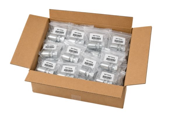
Multi-SKU orders fail visual review when product images cannot be reconciled with labels. The photo sequence should preserve the chain from purchase-order description to unit, inner pack, carton, and packing list.

Capture readable identifiers

Photograph product markings where required, inner labels, carton labels, batch or lot identifiers, carton numbers, and shipping marks. Text should be in focus and not hidden by tape, glare, folds, or hands. The recorded model description, port and hose dash, angle, quantity, and batch should match the approved order and packing records.

A readable label is evidence about the label, not automatic proof about every part inside. Pair label images with a representative identified product group and package opening where appropriate. If different SKUs share a carton, the image set should show how each inner pack remains separated and identified.

Prevent model mixing in the photo process

Photograph one SKU group at a time in a controlled area, then return it to the correct package before beginning the next group. Avoid arranging many similar models for an impressive group shot, because the handling itself can create mixing. Use temporary order-line cards that do not replace or obscure the permanent label.

When one SKU has multiple batches, make that distinction visible. Do not combine images from separate batches under a single generic filename. The buyer may need different evidence if a batch uses a different approved change, protection method, or inspection record.

Packaging Photos Should Show Protection and Structure

Packaging images matter because a technically correct fitting can arrive damaged, contaminated, or mixed. The buyer needs evidence of how critical surfaces are protected and how the packaging system maintains identity during transport.

Move from inner pack to outer shipment

Show caps or plugs on exposed connections, separation between heavy parts, inner bags or trays where used, inner labels, carton arrangement, carton closure, and external marks. For elbows, flanges, or swivel fittings, capture how protruding faces, nuts, edges, and threads are kept from striking adjacent parts. No single packaging material is mandatory for every design; the image should demonstrate the agreed condition.

Photograph a representative carton before closure and the same carton after closure, using its carton number as the link. If damage prevention depends on dividers or supports, show their placement. An image taken before parts are rearranged for shipping does not prove the final pack retained that structure.

Packing and stock

Include shipment-level context

Carton counts, pallet arrangement, wrapping, straps, and shipping marks may support the logistics review when relevant. Images should show labels without exposing unrelated sensitive information. A pallet photo is useful only when it can be reconciled with carton numbers and the packing list.

Packaging photographs cannot guarantee arrival condition. They establish a pre-shipment reference that can later be compared with carrier, receiving, and unpacking evidence. Preserve original files and timestamps where the process relies on them, without assuming metadata alone proves authenticity.

Connect Every Image Group to Order Lines and Quantities

An orderly naming system turns photographs into reviewable records. The goal is to let a person who did not attend the inspection find the relevant SKU, batch, package, and view without guessing.

Use a simple reference structure

Create a photo index or folder structure based on purchase-order line, SKU, batch, and carton. File names can add view descriptions such as overall, connection, hose-end, label, inner-pack, or carton. Keep the structure short enough that staff will actually use it and consistent enough to prevent files from being overwritten.

For example, the naming pattern—not a fabricated order result—might follow order-line_SKU_batch_view. This explains the relationship without prescribing one universal software system. If a photo shows a measured feature, link it to the controlled inspection report rather than encoding an unverified measurement in the filename.

Reconcile quantity evidence carefully

A photograph is rarely a reliable way to count hundreds of small, overlapping fittings. Use piece counts, package quantities, carton labels, packing lists, and inspection records as the primary quantity controls. Photos can show labeled bundles, rows, layers, or sealed inner packs that support the record, but should not replace reconciliation.

Before shipment, compare:

Avoid Common Pre-Shipment Photo Mistakes

Poor evidence often results from unclear intent rather than too few images. Each photograph should answer a defined confirmation question and remain linked to the product it represents.

Images that create false confidence

Avoid blurred label photos, distant pallet images, fittings held in a hand with the ends covered, mixed-model group shots, repeated views of the same easy surface, and screenshots compressed until threads are unreadable. Do not photograph only the cleanest sample if the request concerns batch protection or separation. Do not reuse a previous order’s images without identifying them as historical references.

Another mistake is accepting a ruler photo as full dimensional verification. Camera angle, reference alignment, scale placement, and hidden datums can make the apparent value unreliable. Use a current drawing and dimensional report with defined characteristics, tools, units, and batch identity.

Neutral photo-request checklist

Before closing the review, confirm:

Conclusion

Effective one-piece fitting pre-shipment photos form a traceable visual chain from each purchase-order line to the complete product, connection details, hose side, marking, inner package, carton, and shipment unit. General warehouse pictures and mixed-model arrangements may look reassuring while leaving the main verification questions unresolved. Build a proportionate image list around product geometry and order risk, use readable SKU and batch references, and connect every file group to labels and packing records. Review critical surfaces and protective measures without forcing or altering the fittings. Before authorizing shipment, reconcile images with drawings, inspection reports, quantities, and approved deviations. Photographs can expose visible mismatches and improve later receiving comparisons, but they cannot prove material, dimensions, pressure suitability, hose compatibility, or complete conformity.

FAQ

How many photos are required for each fitting SKU?

There is no universal number. Request only the views needed to identify the product, expose its critical visible features, and show its labels and protection for the specific geometry and order risk.

Should every piece in a bulk order be photographed?

Usually photographs support the approved inspection plan rather than documenting every individual piece. The required scope depends on risk, agreement, batch structure, and the evidence needed for the purchasing decision.

Can a close-up prove the thread standard?

No, a close-up can screen visible form and damage but cannot reliably establish the complete thread standard. Use drawings, dimensions, pitch or TPI checks, taper confirmation, and suitable gauges.

Are carton photos enough to verify shipment quantity?

No, they support but do not replace quantity records. Reconcile purchase-order lines, inner-pack counts, carton labels, carton totals, packing lists, and receiving records.

What should happen when the photo set shows mixed models?

Pause confirmation for the affected group and request separated, identified evidence. Verify labels, packing records, quantities, and product features before accepting the shipment presentation.

Is Free Female Swivel Fitting Rotation Enough

Is Free Female Swivel Fitting Rotation Enough?

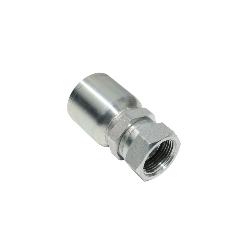
Free female swivel fitting rotation is useful, but it is not enough to approve the assembly. A nut can rotate while its threads, sealing seat, retention feature, or adjacent surfaces are damaged; another nut may feel tight because of contamination, packaging pressure, surface condition, or an assembly issue that still needs investigation. Hand feel alone cannot define a universal acceptance limit. A reliable review combines controlled movement checks with visual inspection, product identity, applicable drawing requirements, sample comparison, and batch evidence.

Free Rotation Confirms Only Limited Movement

A freely rotating nut confirms that it can move around the fitting at the time and under the conditions of the check. It does not prove that the nut will engage the intended male connection correctly or form the specified seal.

1FU43 crimp hydraulic fittings Topa

What the movement check can reveal

Slow, nondestructive rotation can screen for obvious seizure, repeated binding, gritty movement, or a sudden stop. Comparing several units from the same SKU and an approved reference may expose unusual variation. The check is most useful when the inspector records the fitting’s identity, temperature and cleanliness conditions where relevant, and whether protective packaging was just removed.

Movement should be evaluated through the permitted range without using tools or applying force beyond the approved method. A swivel is not a test bearing, and aggressive spinning can mask the original feel or cause damage. If the procedure does not define manipulation, observation may be safer than experimentation.

What rotation cannot establish

Rotation does not identify thread form, diameter, pitch or TPI, straight or tapered geometry, or male/female pairing. It also does not confirm the seat angle, sealing face, O-ring arrangement, or connection standard. A nut may spin normally even when the part is the wrong model or when a thread crest is damaged farther inside.

Nor does rotation verify the hose side. A one-piece fitting has a body or stem and ferrule preassembled, attached, or retained together, but that structure does not guarantee compatibility with a hose construction, hose series, crimp machine, die set, or crimp specification. Swivel movement is one incoming characteristic, not approval of the complete hose assembly.

Interpret Stiffness, Looseness, and Binding Separately

Different movement symptoms point to different questions. Labeling every unusual feel as a dimensional defect can lead to false rejection, while dismissing it as “normal tightness” can move a real issue into inventory.

Stiffness and binding are not identical

Stiffness describes higher-than-expected resistance that may remain fairly uniform. Binding is a localized catch, rough point, or interruption during movement. Possible contributors include contamination, surface residue, impact, deformation, incorrect assembly, burrs, protective material contact, or differences in the approved construction; the symptom alone does not establish the cause.

One tight nut does not automatically prove the dimensions are wrong. First check for cap contact, debris, corrosion, packaging pressure, temperature-related residue behavior, and visible damage, then compare with the approved method and technical requirements. Do not add lubricant, force the nut, disassemble it, or modify the retention area unless an authorized procedure explicitly allows it.

Looseness and axial movement need context

Swivel designs require clearance to rotate, so some movement may be inherent in the assembly. The relevant question is whether rotational and axial conditions meet the current approved design and inspection criteria, not whether the nut feels completely rigid. Without a drawing or approved limit, an inspector should record the observation rather than invent a universal play value.

Excessive apparent looseness may raise questions about retention, missing components, wear, deformation, or incorrect assembly. Compare like-for-like units, observe whether the nut remains securely retained, and inspect the surrounding body and sealing features. A freely rotating nut that can move out of its intended retained position is not approved merely because rotation is easy.

Inspect the Nut, Threads, Seat, and Retention

The swivel assembly should be reviewed as a group of functional features. Rotation that feels acceptable cannot cancel damage found on the nut, thread, sealing seat, or retention interface.

Nut and thread condition

Inspect flats, edges, wrenching surfaces, thread entry, accessible thread flanks, and the inner cavity for impact, crushing, contamination, corrosion, or raised material. The nut should correspond to the correct SKU and connection description. Starting a random mating part is not a safe identification method and can cross-thread or damage a surface.

Thread verification may require the approved drawing, correct gauge, or controlled mating reference. Keep thread form, pitch, diameter, taper, seat, and sealing method as separate characteristics. Similar-looking JIC, SAE, NPSM, metric, BSP, and other female swivels must not be assumed interchangeable.

1FU43 crimp hydraulic fittings

Sealing seat and nut retention

Examine the sealing seat with suitable lighting and access. Scratches, dents, embedded debris, corrosion, or raised edges can matter even if the nut rotates freely. Do not use sealant to compensate for an incorrect seat, damaged face, wrong thread standard, or cross-threaded connection.

The retention feature keeps the nut associated with the fitting while allowing intended movement. Inspect for missing elements, deformation, cracks, unusual gaps, contact marks, and evidence that the nut has struck the body or packaging. Do not dismantle the assembly during routine receiving simply to view a hidden feature unless the approved inspection plan requires and controls that action.

Key inspection items include:

Transport and Packaging Can Change Swivel Condition

A swivel that passed final inspection can arrive with different movement if the nut was loaded, contaminated, or struck during transport. Packaging review helps separate a product characteristic from damage introduced after production.

Impact, abrasion, and compression

Heavy fittings moving together inside a carton can strike nut edges, threads, ferrules, and sealing ends. A bag may keep pieces together without preventing metal-to-metal contact. Carton compression can transfer load through a cap or nut, while abrasive particles from damaged packaging may enter the swivel cavity.

Look for patterns: multiple nuts marked on the same side, caps pushed inward, torn bags, loose dividers, or damaged cartons. A single dent has a different evidence trail from repeated binding across intact packages. Preserve the packaging long enough to document its relationship to the finding.

Protection must not interfere with the assembly

A cap or plug should protect the connection without engaging incorrectly, contacting the sealing seat, trapping debris, or loading the nut. There is no single packaging method suitable for every fitting geometry. The agreed solution should consider weight, shape, exposed threads, swivel travel, shipment route, and warehouse handling.

After an inspector removes protection, the accepted item should be reprotected according to the defined process. Leaving a nut open on a bench can introduce the very debris later blamed on shipment. Maintain separation and identification throughout inspection, repacking, binning, and counter sales.

Approved Samples Establish a Movement Baseline

Sample review should produce a written and visual baseline rather than a memory of how one nut felt. The baseline must also record which characteristics were not verified.

Capture more than subjective feel

Link the approved sample to its part number, drawing revision, connection, batch, and inspection record. Record the permitted movement check, nut position, retention condition, thread and seat results, packaging arrangement, and clear photographs. If no quantified resistance or play criterion exists, describe the controlled comparison method without inventing a number.

Subjective observations can support inspection when they are repeatable and paired with objective checks. They should never be the sole basis for approving thread geometry, sealing condition, or retention. Retain the sample in a way that prevents corrosion, contamination, handling wear, or mix-up from changing its value as a reference.

Reconfirm after changes

If the drawing, nut, retention method, finish, protective cap, assembly process, or packaging changes, determine whether the sample remains valid. A change is not automatically a defect, but undocumented change undermines comparison. Record the decision and the effective batch so later incoming results use the correct baseline.

One acceptable sample also does not prove every unit in the first or repeat order is consistent. Batch-linked inspection remains necessary, particularly when new packaging, long transport, or multiple similar swivel SKUs increase the chance of damage or mixing.

Incoming Inspection Needs a Repeatable Sequence

A repeatable sequence reduces variation between inspectors and helps preserve evidence when a finding appears. It should use an approved sample scope and acceptance basis suited to the order, not a universal frequency invented for all products.

1GU77 crimping hydraulic hose fitting

Screen identity before movement

Confirm purchase-order line, SKU, label, connection, angle, batch, and package identity before handling the nut. Review cap and carton condition, then observe the assembly for visible displacement, impact, corrosion, or contamination. This prevents an inspector from comparing two similar but different female swivel models.

Perform the authorized movement check with clean hands or suitable protection and without force. Note uniformity, local binding, gritty feel, retained position, and visible axial behavior. Continue with thread, seat, body, ferrule, and hose-side inspection because a normal movement result does not waive those checks.

Contain and record unexpected conditions

When a fitting differs from the baseline, hold it and identify the carton, inner pack, batch, and nearby units. Capture an overview and close-up before cleaning or repacking. Record the exact observation—such as binding at one position or damaged thread entry—instead of a vague label like “bad swivel.”

Review the approved criteria and decide whether broader inspection, technical clarification, or controlled disposition is required. Keep held items away from accepted bins. Do not attempt to make the movement feel normal through lubricant, tools, repeated forcing, or unauthorized disassembly.

Common Acceptance Mistakes Create False Confidence

The fastest swivel check is not always the most informative. Accepting all freely rotating nuts and rejecting every stiff nut ignores both hidden defects and legitimate construction or condition differences.

Mistakes to remove from the process

Do not spin only one sample from the top of a carton. Do not judge different SKUs by a single hand-feel reference. Avoid mating with an unidentified adapter, using pliers on the nut, cleaning away residue before recording it, or treating finish color as proof of material and quality.

Do not classify a fitting as compatible because its female swivel resembles a branded reference. Parker-style identifiers support comparison, but complete replacement verification still requires thread, seat, sealing method, dimensions, hose side, material, crimp data, pressure, temperature, fluid, and application review.

Neutral swivel-condition checklist

Before accepting stock, confirm:

Conclusion

Female swivel fitting rotation is a valuable screening characteristic, but free movement is not an acceptance certificate. Inspectors should distinguish uniform stiffness, localized binding, gritty movement, apparent looseness, axial condition, and retention rather than relying on a single hand-feel judgment. The nut, thread entry, accessible threads, sealing seat, body, protection, and package history all contribute evidence. Before releasing a batch, confirm the exact SKU and connection, compare movement under an approved method, review the current drawing and sample, and document any transport-related change. Never force, lubricate, disassemble, or modify a questionable swivel without authorization. Most importantly, remember that rotation quality does not independently prove thread identity, sealing performance, hose compatibility, valid crimp data, pressure suitability, or safe application.

FAQ

Should every female swivel nut rotate with the same hand feel?

Not necessarily, because design, finish, residue, temperature, and approved clearance can influence feel. The relevant comparison is the controlled requirement and like-for-like baseline, not an invented universal sensation.

Can a freely rotating nut still have damaged threads?

Yes, rotation occurs around the fitting body and does not prove thread integrity. Inspect the thread entry and accessible flanks, then use the applicable technical verification method.

Is a tight swivel automatically defective?

No, tightness is a symptom that requires investigation. Check contamination, packaging contact, impact, corrosion, and the approved construction before deciding disposition.

May receiving staff add oil to improve swivel movement?

Not without an approved procedure. Added lubricant can hide the original condition, contaminate the connection, or be incompatible with the seal, fluid, or application.

Does swivel inspection approve a Parker 43-style replacement?

No, it addresses only part of the fitting’s condition. Replacement approval still requires verified connection, seal, dimensions, material, hose side, crimp data, and application requirements.

How to Check One Piece Fitting Bore Cleanliness

How to Check One Piece Fitting Bore Cleanliness

One piece fitting bore cleanliness and sealing-face protection should be confirmed before a commercial order enters usable inventory. A correct-looking TP43-style reference can still contain machining chips, metal particles, oil residue, dust, fibers, or handling contamination, while an exposed flare seat, ORFS face, thread, or O-ring groove may be scratched during packing and transport. These conditions can create first-use concerns, inspection delays, and contamination risk, even when the requested model appears correct.

Internal Cleanliness Matters Before First Use

The fitting bore is part of the fluid path, so material left inside it may move into the hose assembly or hydraulic circuit. Receiving inspection should prevent visibly questionable fittings from being binned with accepted stock, but the required cleanliness level must come from the application and approved contamination-control requirements.

crimp Fitting surface check

Contamination can travel beyond the fitting

Loose chips or particles may migrate during unpacking, assembly, flushing, or equipment operation. Depending on the circuit, foreign matter can contribute to seal damage, restricted passages, valve problems, surface wear, or repeated cleaning work.

A clean external surface does not show the full condition of an internal passage. Elbows, transitions, cross-drilled areas, deep bores, and hose-side features may hide debris from a quick front view. Lighting, magnification, access, and the geometry of the particular fitting influence what an inspector can see, so the method should be defined rather than reduced to a glance.

Clean-looking is not contamination-free

Visual screening can find obvious chips, dust, fibers, pools of oil, or damaged protection. It cannot prove that microscopic particles, incompatible residues, or material trapped beyond the viewing path are absent. When an application requires a specified contamination-control process, acceptance must rely on the appropriate procedure and evidence, not on appearance alone.

The decision also depends on what happens after receiving. A fitting may be cleaned, assembled, flushed, or handled under a controlled process, but those later steps do not justify accepting unknown residue without review. The receiving baseline should state what condition is expected on arrival and what approved preparation remains necessary before installation.

Identify the Source and Type of Contamination

Machining residue, storage contamination, and handling damage are different problems. Correct classification directs the investigation toward production cleaning, packaging integrity, warehouse practices, or transport protection.

Machining and process residue

Metal chips, small curls, abrasive particles, thread-forming debris, or residue near intersecting passages may originate during manufacturing. Oil or process fluid can be intentional for corrosion control or left from machining, but its acceptability depends on the agreed condition and application. An inspector should record location, apparent form, mobility, and affected batch without declaring chemical identity from sight or smell.

Burrs are not the same as loose contamination. A burr remains attached to an edge and may affect flow, assembly, or downstream cleanliness if it breaks away. Do not scrape, pick, or remove it during routine receiving unless an approved inspection or rework procedure authorizes that action.

Storage and handling contamination

Dust, carton fibers, damaged bag fragments, moisture evidence, fingerprints, or mixed loose parts often point toward exposed storage or handling. A protective cap that has fallen off can allow debris to enter even if the fitting left production clean. Compare inner packaging, cap fit, bag closure, carton condition, and the location of contamination to understand when exposure may have occurred.

Handling damage can produce new contamination as well as scratches. Metal-to-metal contact between loose fittings may abrade threads, ferrules, nuts, or sealing faces and create particles inside a shared bag. Because the result can affect several pieces, inspect the package as a unit instead of cleaning one visible fitting and returning it to stock.

Common contamination observations include:

Protect the Surfaces That Create the Connection and Seal

The highest inspection priority belongs to features that guide assembly, carry a seal, or provide a sealing interface. Cosmetic marks on a nonfunctional area and damage on a flare seat should not receive the same decision.

check before order

Threads and sealing faces need different checks

Male and female threads should be protected from impact, crushing, cross-contact, and embedded debris. Thread condition affects engagement, but normal start-up by hand does not prove the standard, pitch, taper, or dimensional conformity. When identity or geometry is in question, use the current drawing and appropriate inspection method rather than forcing a mating part.

Flare seats, flat ORFS faces, cone seats, flange faces, and other sealing surfaces require clean, undamaged contact areas. Scratches, dents, raised material, corrosion, or contamination may disrupt the intended seal. Thread sealant cannot correct a damaged face, wrong seat angle, or mismatched connection standard.

O-ring grooves and seals require coordinated protection

An O-ring groove should be screened for debris, edge damage, corrosion, and anything that may pinch or cut the specified seal. If an O-ring is supplied, also inspect its presence, position, and visible condition without claiming that appearance identifies its material. Protective plugs or caps should shield the area without pressing, scraping, or displacing the seal.

The fitting style changes which surfaces are exposed. A female swivel may protect some geometry inside the nut while leaving threads, the seat, or the nut edge vulnerable to embedded debris and impact. A flange can present a broad face vulnerable to abrasion. The inspection plan should map the actual connection, not use one generic view for every SKU.

Packaging and Handling Preserve the Accepted Condition

Cleaning controls are ineffective if the fitting is exposed or damaged after inspection. Packaging should keep the product identifiable, separated where necessary, protected at critical surfaces, and reasonably isolated from dust, abrasion, impact, and moisture expected in the agreed distribution route.

Match protection to the connection

A cap or plug should fit the intended connection without cutting threads, contacting a sealing surface improperly, or displacing an O-ring. One cap design is not automatically suitable for every thread, angle, or face. The buyer should specify the required protected condition and let the approved packaging solution reflect product geometry and transport risk.

Inner bags, dividers, trays, wraps, or other methods can reduce metal-to-metal contact, but no single material is universally required. Consider part weight, sharp edges, swivel movement, carton loading, shipment method, storage duration, humidity, and warehouse handling. Packaging that looks neat but allows heavy fittings to strike each other does not control the critical risk.

Maintain protection through warehouse handling

Receiving staff should avoid opening every package in a dusty area or leaving caps off after inspection. If a sample must be removed, define how accepted fittings are reprotected and relabeled. Broken packaging, loose components, or mixed SKUs should remain controlled until identity and condition are restored.

Counter sales and partial-carton picking can change the condition long after arrival. Use storage bins and handling steps that protect the bore and connection face, keep model labels with the product, and prevent returns or used parts from entering new inventory. Shipping protection is therefore a chain, not a one-time factory photograph.

Request Evidence That Answers a Specific Question

Pre-shipment evidence should show product identity, critical surfaces, cleanliness controls, and protection, not merely a closed carton. The request can be proportionate to order risk and does not need a fixed number of photographs for every SKU.

Useful pre-shipment evidence

Ask for overview images that link the product to its model and batch, plus close views of the bore, connection end, sealing face, hose side, cap or plug, inner packaging, and carton label where relevant. A documented inspection record may identify the method, sample scope, result, batch, and reviewer. If a specified cleanliness test or process is required, request the agreed record rather than interpreting a photograph as a test.

Image file names or grouped references should map to purchase-order lines. Mixed parts in a single image can hide whether the correct connection, cap, label, and quantity belong together. The evidence should make questions easier to resolve before shipment, while recognizing that it cannot replace the buyer’s receiving inspection.

Standard crimp Fitting

Avoid unsupported conclusions

Do not treat an inspection photo as proof that every unit is clean. Do not infer material, pressure capacity, or hose compatibility from surface appearance. A document titled “quality report” is useful only when its product, revision, method, batch, and results correspond to the order being reviewed.

When evidence is incomplete, record the open item and decide whether shipment, receiving hold, or additional inspection is appropriate under the purchase agreement. Silent assumptions are especially risky in multi-SKU orders because a strong record for one model may not apply to another.

Incoming Inspection Should Prioritize Risk

Incoming inspection should first confirm identity and packaging integrity, then inspect the areas most likely to carry contamination or functional damage. A risk-based plan can use SKU history, batch changes, connection type, packaging damage, and application criticality, but its frequencies and acceptance limits must be approved rather than invented.

Sequence the inspection

Start with purchase order, packing list, SKU label, batch reference, and carton condition. Open packages in a suitable area, preserve separation, and review protection before removing it. Inspect bores and passages with appropriate light and viewing access, then examine threads, seats, faces, grooves, O-rings, swivel nuts, stems, and ferrules without forcing or modifying the assembly.

If visible debris is present, do not blow it toward people or into the workplace. Follow the approved containment, cleaning, and personal-protection procedure for the suspected material and application. A fitting should not be declared acceptable merely because an inspector removed the visible particle.

Document and contain findings

Record the exact SKU, batch, package, feature, and condition. Use clear photographs that show both context and detail. Keep accepted, uninspected, held, and rejected quantities distinct so an uncertain piece cannot return to a saleable bin.

Investigate patterns across related packs before deciding the scope. A damaged carton may indicate transport exposure, while repeated chips in intact packages may point elsewhere. The aim is to find and control the source, not to assign blame from appearance alone.

Common Mistakes Hide Cleanliness and Protection Risk

The most common mistakes occur when receiving teams use speed as a substitute for defined acceptance. A brief check can be useful screening, but it should not claim more than it demonstrates.

Weak acceptance practices

Checking only the shiny exterior misses internal passages. Wiping a sealing face before photographing it removes evidence. Forcing threads to “test fit,” scraping a burr, removing an O-ring, or spraying an unknown cleaner can damage the product or create an incompatible residue.

Other errors include accepting mixed unlabeled parts, assuming oil always means contamination, assuming any oil is acceptable corrosion protection, and treating intact cartons as proof of intact faces. The correct response depends on the agreed condition, application, evidence, and inspection method.

Neutral cleanliness and protection checklist

Before releasing the fitting to inventory, confirm:

Conclusion

One-piece fitting bore cleanliness and sealing-face protection should be controlled from final inspection through packing, transport, receiving, storage, and picking. Visual screening can reveal chips, fibers, residue, corrosion, damaged caps, or scratched faces, but it cannot prove that a fitting is contamination-free or ready for every circuit. Buyers should distinguish machining residue from storage exposure and handling damage, prioritize fluid passages and sealing features, and link evidence to the correct SKU and batch. Before accepting stock, verify product identity, packaging integrity, bore and passage condition, threads, seats, faces, grooves, O-rings, and any required cleanliness process. Preserve the original evidence, contain uncertain items, and follow application-specific cleaning and acceptance requirements rather than relying on appearance alone.

FAQ

Can a new fitting contain oil and still be acceptable?

Yes, some residue may reflect an agreed process or corrosion-control condition. Its identity and acceptability must be verified against the purchase specification and application rather than assumed from appearance.

Are protective caps proof that the bore stayed clean?

No, caps reduce exposure but do not prove cleanliness. Check cap fit, package integrity, internal condition, and any required cleanliness evidence.

Should receiving staff use compressed air to clean a fitting?

Only under an approved and safe cleaning procedure. Uncontrolled air can propel debris toward people, spread contamination, or move particles deeper into a passage.

Does a scratched outer surface require rejection?

Not automatically, because location and severity matter. Distinguish a cosmetic mark from damage to a thread, sealing face, groove, flange face, or other controlled feature.

Can shipment photos replace incoming cleanliness inspection?

No, photographs support pre-shipment review but do not establish every unit’s arrival condition. Receiving must still verify packaging, identity, critical surfaces, and the specified cleanliness requirements.

How to Ensure O-Ring Consistency in One-Piece Fittings

How to Ensure O-Ring Consistency in One-Piece Fittings

One-piece fitting O-ring assembly consistency matters because every fitting in a repeat or bulk order must arrive with the specified seal in the specified condition, not merely with an O-ring that looks acceptable. A missing, incorrect, twisted, pinched, contaminated, or damaged seal can delay receiving, cause rework, and create leakage risk after assembly. Yet O-ring condition is only one part of fitting conformity; it does not prove that the thread, sealing face, hose side, or pressure suitability is correct.

Bulk Orders Increase the Cost of Inconsistent O-Ring Assembly

An O-ring problem becomes a batch-control issue when the same condition may affect many fitting packages or order lines. A single acceptable sample gives useful reference evidence, but it cannot prove that later production, assembly, handling, and packing remained controlled.

one piece Fitting cross reference

Small errors multiply across inventory

In a trial order, staff may notice and isolate one missing or displaced seal during detailed inspection. In a larger order, the same issue can pass through receiving, binning, counter sales, and hose assembly before anyone recognizes a pattern. The resulting work includes separating stock, checking mixed cartons, finding affected customers, and deciding whether replacement O-rings can be used under an approved procedure. A low-cost component can therefore create a high operational burden without any need to invent a complaint rate.

Bulk purchasing also increases the chance that multiple O-ring sizes, materials, groove designs, or connection types are present in one shipment. Visual similarity makes identification harder, especially when loose seals are found in a bag or carton. The buyer needs product-level identity, batch links, and an agreed inspection method rather than an assumption that any seal fitting the groove is correct.

Consistency is narrower than complete performance

O-ring assembly consistency means the specified O-ring is present, correctly positioned, visibly undamaged, clean, and assembled in the intended groove condition across the reviewed batch. It does not establish material compatibility, pressure capability, temperature suitability, or complete fitting performance. Those decisions still depend on the approved specification, fluid, application, connection design, and the lowest-rated component in the assembly.

A well-installed O-ring also cannot compensate for a damaged sealing face, an incorrect thread standard, a wrong groove, or a mismatched port. Likewise, a one-piece fitting—where the body or stem and ferrule are preassembled, attached, or retained together—does not automatically guarantee hose compatibility or a valid crimp. Treat the O-ring review as one controlled acceptance layer within a broader technical verification process.

Define Which O-Ring Conditions Are Controlled

The inspection baseline should distinguish facts that can be checked visually from characteristics that require documents, measurements, or material evidence. This boundary prevents a clean-looking seal from being accepted as the correct seal without support.

Presence, position, and visible condition

Incoming inspection can confirm whether the O-ring is present in the designated location and whether it appears seated rather than hanging loose, rolled out, or trapped against another feature. Inspectors can also screen for cuts, nicks, flattening, twisting, pinching, foreign material, and obvious deterioration. Lighting and viewing angle matter because a seal may be partly hidden by a nut, groove wall, or protective cap.

The groove and nearby sealing surface deserve equal attention. Burrs, sharp edges, corrosion, impact marks, or contamination can damage an otherwise correct O-ring during assembly or installation. A finding should therefore identify whether the concern is the seal, the groove, the surrounding hardware, or handling after production.

Size and material require technical evidence

Appearance alone cannot confirm O-ring material, formulation, hardness, or exact size. Similar-looking seals may behave differently with fluid, temperature, pressure cycles, and storage exposure. Confirm the specified identity through approved drawings, bills of material, controlled part references, batch evidence, or another agreed technical record; do not replace a suspect seal based only on color or apparent fit.

Missing, Incorrect, and Damaged Seals Create Different Risks

Not every O-ring nonconformity has the same cause or corrective action. Classifying the condition accurately helps the buyer contain the right stock and request evidence relevant to the failure.

Read the condition before choosing an action

A missing seal is an identity and completeness problem. A damaged seal is a condition problem that may also indicate a groove, tool, or handling issue. An apparently different seal is an evidence problem until the specified identity is confirmed. Keeping these categories separate prevents an unverified replacement from hiding the original cause.

One acceptable replacement does not authorize staff to rework an entire batch. Any reinstallation or substitution must follow an approved procedure that covers seal identity, cleanliness, tools, inspection, and traceability. If the process is not defined, the safer commercial decision is to hold the stock and obtain technical direction.

Samples and First Orders Must Establish a Baseline

Samples are most useful when approval records exactly what was reviewed and what must remain consistent. A verbal “looks good” decision leaves later inspectors without a defensible comparison.

Record technical and visual references separately

The baseline should link the sample to the part number, drawing revision, connection type, O-ring specification reference, groove requirement, assembly state, and inspection record. Controlled photographs can document presence, position, general appearance, cap arrangement, and label identity. They should not be treated as proof of material or exact dimensions.

10C43 hydraulic crimp fitting Topa

Record any limitation in the sample review. For example, if material evidence was not available, state that material approval remains open rather than silently treating visual acceptance as technical approval. This prevents a first commercial order from inheriting assumptions that were never verified.

Preserve the link from sample to first batch

Before approving the first larger order, compare the batch against the same revision and acceptance basis. Confirm whether any O-ring source, assembly method, groove design, protective packaging, or inspection process changed. A change is not automatically unacceptable, but it requires review before the old sample can remain the reference.

Useful baseline records include:

Incoming Inspection Should Combine Screening and Verification

Incoming inspection should first protect the warehouse from mixed or questionable stock, then collect enough evidence for an acceptance decision. The depth of inspection can reflect risk, order history, batch changes, and the buyer’s documented plan, but it should not be improvised after a failure.

Start with identity and containment

Confirm the purchase-order line, product label, model, connection form, batch identifier, and expected O-ring scope before opening mixed packages. Keep inspected, uninspected, accepted, and held quantities physically distinguishable. If different SKUs share similar bodies or seals, compare them one order line at a time so an O-ring from one model is not used as the reference for another.

Use clean handling conditions and inspection tools that will not scratch the sealing face or damage the seal. Do not force a nut, remove an O-ring, lubricate it, stretch it, or probe the groove unless the approved method calls for that action. Inspection should not create the defect it is meant to detect.

Escalate patterns, not just individual defects

When a concern appears, record its exact product identity, carton or inner-pack reference, batch, location on the fitting, and visible condition. Review nearby units according to the inspection plan and look for common packaging, model, or batch links. A repeated condition may justify broader containment, while an isolated handling mark may require a different response.

The incoming decision should connect visual screening with the required evidence:

Batch Records and Photos Support Repeat-Order Review

Records create confidence only when they identify the actual product and batch. Generic certificates, undated photographs, or images of mixed parts cannot show which units were inspected.

Build an evidence chain

The evidence chain may include the approved specification, material or O-ring identity record, assembly check, final inspection, packaging record, batch label, shipment document, and incoming result. The exact documents depend on the agreed scope. Each record should use consistent product and batch identifiers so a future concern can be contained without questioning all stock.

Photos should show enough context to be useful. Pair an overview showing the SKU label and batch reference with close-ups of the O-ring location, groove area, sealing face, and protection method. File names or photo-group labels should map to the purchase-order line; a folder of unnamed images is weak evidence even when the pictures are clear.

Use trends carefully

Comparing several received batches can reveal repeated displacement, cap contact, contamination, or visual changes. A trend is a prompt for investigation, not proof of a specific cause. Review process, handling, packaging, and inspection evidence before assigning responsibility or approving corrective action.

Do not use past acceptance to waive current verification automatically. Repeat-order confidence comes from controlled continuity and transparent change handling, not from assuming that a previous good lot guarantees the next one.

Avoid Common O-Ring Acceptance Mistakes

The most damaging acceptance mistakes collapse technical verification into a quick appearance check. A reliable process makes uncertainty visible and stops it from moving into saleable inventory.

metric 24° oring crimp fitting

Decisions that need correction

Do not accept an O-ring because it is black, looks the same as the sample, rotates in the groove, or appears to fit. Do not assume a loose seal in the package belongs to the fitting beside it. Do not treat a protective cap as proof that the seal beneath it is clean and undamaged.

Other common mistakes include checking only one easy-to-see SKU, mixing held units back into accepted cartons, failing to record the drawing revision, and replacing damaged seals without traceability. These actions may make the receiving area look orderly while preserving the underlying risk.

Neutral O-ring inspection checklist

Before accepting a batch, confirm:

Conclusion

Reliable one-piece fitting O-ring assembly consistency requires more than finding a seal in every groove. The buyer must define the specified O-ring, separate visible checks from material and dimensional verification, preserve a written sample baseline, and link incoming findings to the correct SKU and batch. Missing, displaced, damaged, contaminated, or visually different seals require different investigations, and unapproved replacement can erase traceability without resolving the cause. Before accepting a repeat or bulk order, verify the current drawing, O-ring identity, groove and sealing-face condition, assembly state, packaging protection, inspection evidence, and change history. These controls improve repeat-order confidence while recognizing that O-ring consistency alone does not prove complete fitting, hose, crimp, pressure, fluid, temperature, or application suitability.

FAQ

Can O-ring material be identified by color?

No, color alone cannot reliably identify O-ring material. Confirm the specified material through controlled technical records and evaluate fluid, temperature, pressure, and application requirements before acceptance.

Should a loose O-ring be reinstalled during receiving?

Not unless an approved procedure authorizes it. The seal identity, groove condition, cleanliness, installation method, inspection, and traceability must be controlled before rework.

Does an approved sample prove the bulk batch is consistent?

No, an approved sample establishes a reference but does not prove later-batch conformity. The commercial batch still needs batch-linked evidence and incoming inspection against the current baseline.

Is visual inspection enough when every O-ring is present?

No, presence is only one acceptance characteristic. Visual inspection cannot confirm exact size, material, application compatibility, or complete sealing performance.

What should happen when only a few fittings show damaged seals?

Hold the affected units and review the inspection plan for broader containment. Record the batch and package links, investigate the seal, groove, handling, and protection conditions, and use an approved disposition.

How to Identify SAE 45° One Piece Fittings

How to Identify SAE 45° One Piece Fittings?

SAE 45° one piece fitting identification requires a group of matching observations, measurements, gauge checks, and hose-side records; outside diameter or a flare angleed appearance cannot confirm the order alone. The process must distinguish connection size from measured thread diameter, verify Thread Pitch or TPI and flare angle, identify Male or Female Connection, and rule out JIC 37-degree and other flare candidates. It must then add Hose Dash, Fitting Series, and Straight, 45-Degree, or 90-Degree Configuration.

SAE 45-degree Identity Requires More Than a Swivel Appearance

SAE 45-degree flare is identified by a defined combination of straight thread, 45-degree flare seat, size designation, gender, and connection behavior. Seeing a swivel nut or a familiar flare profile is only an initial clue.

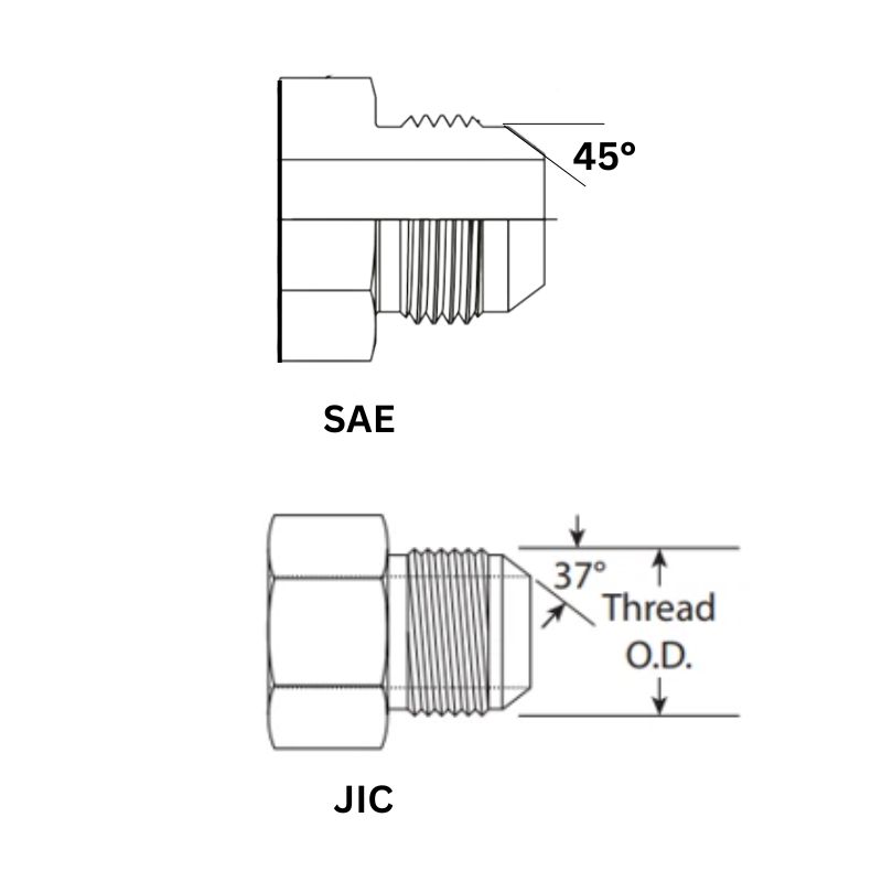
JIC vs SAE

Distinguish SAE 45-degree and JIC 37-degree candidates

SAE 45-degree and JIC 37-degree are flare connection systems, but they should not be treated as identical labels or accepted solely from apparent engagement. Their intended thread and sealing requirements must be checked against applicable controlled data. JIC 37-degree uses a different flare angle even when some thread features appear similar; another flare connection may look close in a photograph or begin to engage before its form, pitch, or flare angle produces an incorrect fit.

A thread name is not a complete order description. Identify whether sealing is intended through the 45-degree flare interface and whether the port, component instructions, or application requires a particular extra tightening or assembly method. Do not confuse that behavior with a other flare, cone, flat-face, or O-ring sealing methods elsewhere in a hydraulic system.

Use appearance and markings only for preliminary screening

Clear photographs of the complete fitting, thread profile, hose tail, and any markings can narrow the candidate list. An old part number may also lead to a drawing or catalog record. Neither source proves the installed component is original, undamaged, correctly marked, or compatible with the current hose and port.

Thread Diameter Alone Does Not Confirm the Connection

connection size is a standardized designation, not a direct statement of the measured thread diameter at a thread crest. A caliper reading must be compared with authoritative reference data together with pitch and flare geometry before a nominal designation is assigned.

Understand what the measurement represents

On a Male Connection, a caliper can record an outside diameter at a documented axial location; on a Female Connection, access and contact geometry differ, so the relevant inside measurement needs an appropriate method and reference. A diameter reading does not reveal the flare angle or condition of the sealing seat. Coating, burrs, wear, damage, dirt, and imperfect jaw placement can also change the result.

The measured value therefore describes a particular part at a particular location, not the name of the size. Record the instrument, location, thread condition, connection gender, access to the seat, and available inspection equipment. Then use verified SAE 45-degree reference data to evaluate the candidate instead of rounding the caliper result to a familiar connection size.

Avoid forcing one measurement into a size chart

A diameter can eliminate some candidates, but it cannot confirm Thread Pitch or TPI, flare angle, or thread form and flare form. Selecting a nominal size from diameter alone may produce an order that appears close yet damages the port, has inadequate engagement, or leaks. If a measurement lies between expected candidates or the thread is damaged, stop and use additional inspection rather than choosing the nearest designation.

Do not derive missing dimensions from an online image, an unidentified sample, or another fitting that “looks the same.”

Each Inspection Tool Confirms a Different Feature

Calipers, pitch gauges, thread gauges, and inspection records are complementary. No single tool proves the complete identity, and every tool must be suitable, serviceable, and used according to its instructions.

Match the tool to the question

Use a pitch gauge only after cleaning the thread without altering it. The gauge leaf should seat consistently across usable threads; do not select the leaf that contacts at one point while gaps remain elsewhere. Record TPI for inch-thread candidates or the applicable pitch expression for other candidates rather than using the words “coarse” or “fine.”

Check the flare seat through a controlled method

flare angle should be evaluated using a suitable gauge or a documented measurement method and verified reference. A visual estimate, thread engagement, or swivel movement is not proof of the required seat angle or sealing-face geometry. The appropriate method depends on connection gender, access to the seat, and available inspection equipment and what inspection equipment is available.

Never force an unknown fitting into a port as a thread gauge. Partial engagement can occur between mismatched flare systems, and added torque can cross-thread or permanently damage both components. If a correct gauge, clean usable thread, or reliable reference is unavailable, record the limitation and keep the result preliminary.

Gender, Hose Side, and Geometry Complete the Fitting Identity

Correctly identifying the pipe thread still does not identify the complete one-piece fitting. The order must include connection gender, hose-side compatibility, and physical configuration.

Record Male or Female Connection precisely

State Male or Female Connection from the actual port end being ordered, not from the mating component or a casual description such as “male hose.” Record relevant swivel behavior, hex or wrench features, and any sealing or orientation detail that affects installation. A female port on the machine does not mean the removed hose fitting should be described as female.

Confirm thread condition at the same time. Flattened crests, torn threads, corrosion, contamination, cross-threading, or previous over-tightening may distort measurements and make the sample unsuitable for final gauging. A damaged sample can still supply clues, but the record must show why further reference or a sound mating component is needed.

Male Hydraulic Crimp Fitting

Separate Hose Dash from the port designation

Hose Dash is the nominal hose-side size and must not be copied from connection size or a port-dash description. Confirm the hose manufacturer, Hose Series, Hose Construction, reinforcement, and dash, then identify the approved Fitting Series, stem, ferrule, Crimping Machine, Die Set, and current crimp data. Equal dash values do not prove hose and fitting compatibility.

Also specify Straight, 45-Degree, or 90-Degree Configuration. For elbows, record the hose-tail direction, orientation, clearance, and swivel or fixed behavior where relevant. The right SAE thread on the wrong fitting angle can make installation impossible or force a hose into excessive bend, twist, abrasion, or movement interference.

Follow a Step-by-Step Identification Process

A controlled sequence preserves evidence and prevents early assumptions from shaping later measurements. Complete the thread decision before translating it into a purchasing description, but retain the hose side and geometry throughout the inspection.

Stage 1: make safe, clean, and document

Before removal, stop the equipment, isolate the hydraulic circuit, release pressure and stored energy, secure raised or suspended loads, and follow applicable lockout and equipment-manufacturer instructions. Never touch a suspected injection leak or loosen a fitting to “see whether pressure remains.” Mark hose orientation and capture installation clearance before moving the assembly if those details could be lost.

After safe removal, protect the port and clean the sample using a method that does not reshape the threads. Photograph the entire fitting, connection end, hose side, markings, and damage. Record the equipment position, mating-port information, old number as an unverified lead, Male or Female Connection, and Straight, 45-Degree, or 90-Degree Configuration.

At this stage, collect:

Stage 2: measure independent thread features

Measure the accessible diameter with a suitable caliper and record the exact location and condition. Check Thread Pitch or TPI with an appropriate pitch gauge, then evaluate flare angle with the correct gauge or documented method. Do not adjust a measurement simply because it conflicts with the expected SAE 45-degree candidate; the conflict is evidence that the assumption, sample, or method needs review.

Compare diameter, pitch or TPI, flare angle, gender, and sealing-face form with current authoritative references. Deliberately compare plausible alternatives, including JIC 37-degree and other straight-thread flare connections, rather than stopping when one SAE 45-degree feature appears to match. If the sample is worn or damaged, use a verified drawing, sound port data, suitable gauge results, or other controlled evidence before final acceptance.

Stage 3: confirm the whole fitting and decision status.

Once the thread candidate is supported, confirm connection size from the verified reference, then add Hose Dash, Fitting Series, ferrule, configuration, material, finish, and critical dimensions. Review application pressure, temperature, fluid, environment, and routing; the lowest-rated component limits the complete assembly. Confirm the current hose and crimp procedure rather than assuming one-piece construction guarantees assembly suitability.

Mark the result as accepted only when every required field has evidence. If the connection is likely SAE 45-degree but seat-angle verification is unavailable, or the hose series cannot be identified, state the unresolved point and keep the record preliminary. A controlled incomplete result is safer than a complete-looking order built on guesses.

Thread Engagement Does Not Create the Flare Seal

The straight threads provide mechanical engagement, while the mating 45-degree flare surfaces create the intended seal. A nut that starts smoothly or reaches an expected position does not prove that the two seats have the same angle, finish, or geometry.

SAE-ORFS-Female-90-permanent

Use the specified assembly procedure

Inspect both sealing faces before assembly. Dirt, scratches, dents, corrosion, deformation, and previous mismatch can interrupt continuous contact even when the thread is correct. Confirm the male flare, female swivel seat, thread designation, material, and current assembly instructions as one controlled combination. For an elbow, prevent hose twist and unintended side loading while the connection is aligned.

If leakage is suspected, stop the equipment, isolate the circuit, release pressure and stored energy, and inspect by an approved method. Never tighten a pressurized connection or touch a suspected high-pressure leak. Repeated tightening may damage the seat, distort the nut, or hide the original identification error.

Know what tightening cannot correct

Extra tightening cannot change a JIC 37-degree seat into a SAE 45-degree seat. It cannot repair crossed threads, a damaged flare, contamination, incorrect gender, or an incompatible hose and fitting series. Partial thread engagement may occur between different systems, but that mechanical contact does not establish the required sealing interface.

Reject any candidate that requires force to start, binds unexpectedly, shows uneven seat contact, or lacks verified flare evidence. Return to the measurement record and compare the actual thread and seat features with controlled drawings or gauges. The objective is matching geometry, not simply achieving a tight-feeling joint.

Prevent Order Errors With a Final Information Checklist

Most bad orders preserve only a thread label and omit the evidence behind it. The purchasing description should allow another qualified person to verify the candidate without handling the original sample.

Review common failure points

Common errors include treating measured thread diameter as connection size, calling every swivel flare connection SAE 45-degree, estimating TPI from a photo, and copying an old number without checking revision or application. Other mistakes are describing the mating port’s gender instead of the fitting, equating Hose Dash with port size, and omitting elbow orientation. Extra tightening is then misused to compensate for a mismatch that should have been stopped at inspection.

Before order approval, confirm:

Conclusion

Reliable identification comes from several independent features agreeing, not from a familiar appearance or one caliper reading. Preserve the installation evidence, distinguish connection size from measured thread diameter, and verify Thread Pitch or TPI, the 45-degree flare angle, gender, seat condition, and sealing behavior with suitable tools and current references. Deliberately rule out JIC 37-degree and other flare candidates before final acceptance. Then complete the order with Hose Dash, Fitting Series, ferrule, Straight, 45-Degree, or 90-Degree Configuration, material, application, and controlled crimp data. Never force engagement or use extra tightening to conceal mismatch. Keep the inspection record with the approved order for future verification. A documented SAE 45-degree one-piece fitting identification process prevents bad orders while protecting the port and the finished hose assembly.

Frequently Asked Questions

Can a mating port be used to identify an unknown fitting?

It can provide supporting evidence when the port identity is verified and both components are undamaged. Do not test an uncertain candidate by forcing it into the port or treating partial engagement as proof.

What if a pitch gauge fits more than one candidate?

Use diameter, flare angle, thread form and flare form, gender, and authoritative references to resolve the candidates. A pitch match alone cannot establish the final standard.

Should coating be removed before measuring a thread?

Do not remove or alter coating unless an approved inspection procedure requires it. Record the surface condition and account for it through the applicable measurement method and reference.

Can a replacement be ordered from the machine model alone?

No, equipment models may have production changes, optional components, imported attachments, or prior repairs. Verify the installed connection, hose side, configuration, and application data.

Is a thread ring or plug gauge enough for final order approval?

No, a correct gauge result addresses specified thread features but not Hose Dash, Fitting Series, configuration, material, or application suitability. The complete fitting record still needs approval.

How Flat Face Sealing Works in ORFS One Piece Fittings

How Flat Face Sealing Works in ORFS One Piece Fittings

ORFS one-piece fitting sealing verification requires a group of matching observations, measurements, gauge checks, and hose-side records; outside diameter or swivel appearance cannot confirm the order alone. The process must distinguish connection size from measured thread diameter, verify Thread Pitch or TPI and flat-face and groove condition, identify Male or Female Connection, and rule out flare, tapered-thread, and other candidates. It must then add Hose Dash, Fitting Series, and Straight, 45-Degree, or 90-Degree Configuration.

ORFS Identity Requires More Than a Swivel Nut

An ORFS connection uses a designed flat-face and O-ring interface for sealing while straight threads and the nut provide mechanical engagement. The swivel nut alone does not prove ORFS because other connection families also use swivel components.

1 2 wire female orfs swivel crimp fitting

Confirm the flat face, O-ring groove, and straight thread

On the male ORFS side, identify the flat sealing face and the designed groove that retains the specified O-ring. On the female swivel side, inspect the mating flat face that compresses the seal. Confirm thread form, diameter, pitch, connection gender, and size with suitable tools and current controlled references; thread engagement is supporting evidence, not proof of the seal design.

The groove, face, and O-ring work as a system. The thread does not replace the O-ring, and thread compound cannot repair a damaged face or an incorrect seal. A fitting that resembles ORFS but lacks the correct groove or mating geometry must remain an unconfirmed candidate.

Rule out other sealing methods deliberately

Flare connections seal through angled metal surfaces, and tapered-thread connections develop their intended joint through different thread geometry and procedures. ORFS instead depends on controlled compression of the correct O-ring between aligned flat faces. These methods are not interchangeable, even if thread dimensions or swivel appearance seem similar.

Photographs can narrow candidates, but final confirmation may require thread measurements, groove and face inspection, a verified drawing, fitting markings, hose-side information, and application records. Keep visual screening separate from final approval.

The Flat Face and O-Ring Must Be Evaluated Together

The flat face supports alignment and compression, while the specified O-ring supplies the resilient sealing element. Either part can defeat the intended ORFS sealing method when damaged, contaminated, incorrectly selected, or assembled out of alignment.

Inspect surfaces and groove condition

Clean the connection by an approved method and inspect for dents, radial scratches, corrosion, embedded debris, deformation, and raised damage that could cross the sealing path. Examine the groove for damage, contamination, or geometry inconsistent with controlled product data. Do not invent groove tolerances or attempt to reshape the groove in the field.

Surface discoloration alone does not establish leakage risk, and a smooth-looking photograph cannot prove flatness or groove conformity. Record the condition, lighting, magnification if used, and the applicable drawing or acceptance reference. Replace or escalate suspect pressure-containing parts according to the approved procedure.

Verify the O-ring as an application component

Confirm the O-ring size, material, condition, source or specification, and compatibility with the fluid, temperature, environment, and equipment requirements. Do not install an O-ring merely because it fits into the groove. Stretching, twisting, cuts, flattening, swelling, hardening, contamination, or an unknown material are reasons to stop and resolve the seal requirement.

Lubrication, installation tools, and replacement rules must follow current component and equipment instructions. Never use thread tape or compound to compensate for an incorrect O-ring or damaged ORFS face.

Surface, Groove, and Seal Checks Answer Different Questions

Calipers, pitch gauges, thread gauges, and inspection records are complementary. No single tool proves the complete identity, and every tool must be suitable, serviceable, and used according to its instructions.

Match the tool to the question

Use a pitch gauge only after cleaning the thread without altering it. The gauge leaf should seat consistently across usable threads; do not select the leaf that contacts at one point while gaps remain elsewhere. Record TPI for inch-thread candidates or the applicable pitch expression for other candidates rather than using the words “coarse” or “fine.”

Check groove and face geometry through a controlled method

flat-face and groove condition should be evaluated using a suitable gauge or a documented measurement method and verified reference. A visual narrowing, changing caliper reading, or partial engagement is not by itself proof of the required groove and face geometry. The appropriate method depends on whether the connection is male or female and what inspection equipment is available.

Never force an unknown fitting into a port as a thread gauge. Partial engagement can occur between mismatched connection systems, and added torque can cross-thread or permanently damage both components. If a correct gauge, clean usable thread, or reliable reference is unavailable, record the limitation and keep the result preliminary.

Hose Side, Series, and Orientation Complete the Part

Correctly identifying the pipe thread still does not identify the complete one-piece fitting. The order must include connection gender, hose-side compatibility, and physical configuration.

hydraulic fitting ORFS 1JS43

Record Male or Female Connection precisely

State Male or Female Connection from the actual port end being ordered, not from the mating component or a casual description such as “male hose.” Record relevant swivel behavior, hex or wrench features, and any sealing or orientation detail that affects installation. A female port on the machine does not mean the removed hose fitting should be described as female.

Confirm thread condition at the same time. Flattened crests, torn threads, corrosion, contamination, cross-threading, or previous over-tightening may distort measurements and make the sample unsuitable for final gauging. A damaged sample can still supply clues, but the record must show why further reference or a sound mating component is needed.

Separate Hose Dash from the port designation

Hose Dash is the nominal hose-side size and must not be copied from connection size or a port-dash description. Confirm the hose manufacturer, Hose Series, Hose Construction, reinforcement, and dash, then identify the approved Fitting Series, stem, ferrule, Crimping Machine, Die Set, and current crimp data. Equal dash values do not prove hose and fitting compatibility.

Also specify Straight, 45-Degree, or 90-Degree Configuration. For elbows, record the hose-tail direction, orientation, clearance, and swivel or fixed behavior where relevant. The right ORFS thread on the wrong angle can make installation impossible or force a hose into excessive bend, twist, abrasion, or movement interference.

Follow a Step-by-Step ORFS Verification Process

A controlled sequence preserves evidence and prevents early assumptions from shaping later measurements. Complete the thread decision before translating it into a purchasing description, but retain the hose side and geometry throughout the inspection.

Stage 1: make safe, clean, and document

Before removal, stop the equipment, isolate the hydraulic circuit, release pressure and stored energy, secure raised or suspended loads, and follow applicable lockout and equipment-manufacturer instructions. Never touch a suspected injection leak or loosen a fitting to “see whether pressure remains.” Mark hose orientation and capture installation clearance before moving the assembly if those details could be lost.

After safe removal, protect the port and clean the sample using a method that does not reshape the threads. Photograph the entire fitting, connection end, hose side, markings, and damage. Record the equipment position, mating-port information, old number as an unverified lead, Male or Female Connection, and Straight, 45-Degree, or 90-Degree Configuration.

At this stage, collect:

Stage 2: measure independent thread features

Measure the accessible diameter with a suitable caliper and record the exact location and condition. Check Thread Pitch or TPI with an appropriate pitch gauge, then evaluate flat-face and groove condition with the correct gauge or documented method. Do not adjust a measurement simply because it conflicts with the expected ORFS candidate; the conflict is evidence that the assumption, sample, or method needs review.

Compare diameter, pitch or TPI, groove and face geometry, gender, and thread form with current authoritative references. Deliberately compare plausible alternatives, including flare and tapered-thread connections, rather than stopping when one ORFS feature appears to match. If the sample is worn or damaged, use a verified drawing, sound port data, suitable gauge results, or other controlled evidence before final acceptance.

Stage 3: confirm the whole fitting and decision status.

Once the thread candidate is supported, confirm connection size from the verified reference, then add Hose Dash, Fitting Series, ferrule, configuration, material, finish, and critical dimensions. Review application pressure, temperature, fluid, environment, and routing; the lowest-rated component limits the complete assembly. Confirm the current hose and crimp procedure rather than assuming one-piece construction guarantees assembly suitability.

Mark the result as accepted only when every required field has evidence. If the thread is likely ORFS but groove and face geometry gauging is unavailable, or the hose series cannot be identified, state the unresolved point and keep the record preliminary. A controlled incomplete result is safer than a complete-looking order built on guesses.

ORFS Threads Engage; the Face and O-Ring Seal

Straight threads draw the two faces together and maintain mechanical engagement; they are not the primary sealing surface. Reliable performance depends on correct alignment, an undamaged interface, the specified O-ring, and the approved assembly procedure.

Assemble without hiding misalignment

Align the fitting before tightening so the faces meet evenly and the hose is not forced into twist or side load. Support elbows and routed assemblies as required, preserve bend radius and clearance, and use the current torque or assembly method from the responsible manufacturer. This article gives no universal torque because size, material, design, lubrication, and instructions vary.

If resistance appears abnormal, stop rather than using torque to pull misaligned components together. Cross-threading, a trapped seal, damaged faces, or incompatible parts may otherwise be concealed until leakage or service damage occurs.

ORFS crimp on Hydraulic fitting Topa

Diagnose leakage safely

Stop equipment, isolate the circuit, release hydraulic pressure and stored energy, secure suspended loads, and follow lockout and equipment instructions before inspection. Never touch a suspected high-pressure leak or tighten the joint while it is pressurized. Use approved inspection methods.

After safe disassembly, preserve the O-ring and component condition for evidence. Check seal identity, groove and face damage, contamination, alignment, thread condition, hose routing, and application data. Replacing only the O-ring without finding the cause can allow the same problem to recur.

Prevent ORFS Errors With a Final Confirmation Checklist

Most bad orders preserve only a thread label and omit the evidence behind it. The purchasing description should allow another qualified person to verify the candidate without handling the original sample.

Review common failure points

Common errors include treating measured thread diameter as connection size, calling every straight thread ORFS, estimating TPI from a photo, and copying an old number without checking revision or application. Other mistakes are describing the mating port’s gender instead of the fitting, equating Hose Dash with port size, and omitting elbow orientation. Thread compound is then misused to compensate for a mismatch that should have been stopped at inspection.

Before order approval, confirm:

Conclusion

Reliable identification comes from several independent features agreeing, not from a familiar appearance or one caliper reading. Preserve the installation evidence, distinguish connection size from measured thread diameter, and verify Thread Pitch or TPI, flat-face and groove condition, gender, thread condition, and sealing behavior with suitable tools and current references. Deliberately rule out flare, tapered-thread, and other candidates before final acceptance. Then complete the order with Hose Dash, Fitting Series, ferrule, Straight, 45-Degree, or 90-Degree Configuration, material, application, and controlled crimp data. Never force engagement or use thread compound to conceal mismatch. Keep the inspection record with the approved order for future verification. A documented ORFS one-piece fitting sealing verification process prevents bad orders while protecting the port and the finished hose assembly.

Frequently Asked Questions

Does a swivel nut prove that a fitting is ORFS?

No, a swivel nut alone does not prove ORFS identity. Confirm the flat mating face, male O-ring groove, straight-thread features, size, and controlled reference before approval.

Can any O-ring that fits the groove be used?

No, physical fit does not prove the correct size, material, or application compatibility. Verify the specified seal against fluid, temperature, equipment, and component requirements.

Can thread compound stop an ORFS face leak?

No, thread compound cannot repair a damaged face, wrong O-ring, or misaligned connection. Isolate and depressurize the system, then inspect the actual sealing interface safely.

Should a flattened O-ring simply be replaced?

Replacement may be necessary, but the cause must also be investigated. Check groove condition, seal identity, assembly procedure, alignment, fluid exposure, and service history before reassembly.

Is ORFS always better than a flare connection?

No, ORFS is not universally superior to every connection. Its suitability depends on equipment design, application conditions, hose and fitting compatibility, installation controls, and correct seal maintenance.

How to Restock One Piece Fittings Every Quarter

How to Restock One Piece Fittings Every Quarter

One-piece fitting quarterly restocking should be a decision review, not an automatic order placed every three months. A reliable plan combines actual consumption, stock on hand, open orders, lead time, emergency demand, seasonal changes, and the risk of confusing similar SKUs. Ordering from last quarter’s purchase list alone can repeat excess stock while leaving critical combinations unavailable. The review should decide which items to increase, maintain, reduce, hold, or stop, with technical compatibility preserved for every SKU. This article provides a practical framework for teams that manage many fitting connections, hose sizes, and configurations without imposing a universal reorder quantity or service target.

Calendar Dates Do Not Determine Replenishment Need

A quarterly schedule is useful for reviewing data, but the calendar does not prove that every item needs a purchase order. Demand, supply exposure, and technical relevance vary by SKU, so the same review date can lead to different actions.

order of one piece Fitting

Separate the review cycle from the order cycle

Reviewing every quarter creates a regular decision point for cleaning data, identifying risks, and approving exceptions. It does not mean buying every SKU every quarter. A fast-moving item with long replenishment lead time may require action between reviews, while a slow-moving item with sufficient usable stock may require no order for several cycles. Treat the quarterly meeting as governance around ongoing replenishment rather than the sole trigger for purchasing.

Avoid repeating historical purchase errors

Purchases are not the same as demand. A large prior order may reflect an old promotion, a minimum shipment arrangement, a one-time project, or correction of a previous stockout. Actual issues to production, repair, or customer orders show consumption more clearly, but even usage must be checked for returns, cancellations, transfers, and unusual emergency events. When the planning method copies prior purchase quantities, it can amplify an earlier mistake.

Build the Review From a Complete Data Set

The decision should begin with one SKU-level view of demand, supply, and availability. Data from separate systems can be used, but definitions and timing must align before comparisons are made.

Reconcile demand and supply positions

For each controlled part number, examine sales or usage history, current usable stock, allocated stock, open customer demand, open purchase orders, expected receipts, backorders, returns, and lead time. Remove quarantined or unidentified fittings from available stock until they are verified. An on-hand number that includes damaged packages, mixed bins, or items pending inspection overstates the inventory that can safely fulfill an order.

Demand history should retain context. Separate normal repeated use from projects, stocking transfers, emergency breakdowns, and data corrections. An emergency issue may deserve more weight when the same machine population remains active, but it should not automatically convert an uncommon fitting into a high-volume item.

Include technical and market context

Inventory data alone cannot show whether a SKU is still appropriate. Review local connection standards, equipment population, common hose series, port dash and hose dash combinations, hydraulic fitting angles, customer application patterns, and replacement history. Imported machines, new attachments, or changing service territories can introduce BSP, Metric, JIC, ORB, NPT, or other needs that are not visible in an old purchasing template.

The review package should include:

Classify Movement Without Relying on Fixed Thresholds

Fast, medium, and slow movement are relative categories that should reflect the operation’s actual demand and risk. A universal number of issues per quarter would ignore lead time, equipment criticality, item value, and the consequences of a stockout.

Use repeatability as well as volume

A fast-moving SKU normally has recurring, reasonably predictable consumption across multiple periods. A medium-moving item may have repeat demand with wider gaps or greater variability. A slow-moving item may be rarely requested, project-specific, or uncertain. Classification should look at frequency, recency, quantity pattern, customer concentration, and whether usage is normal or exceptional.

One large issue does not necessarily make a fitting fast-moving. Conversely, a low-volume fitting used repeatedly on critical equipment may deserve a different availability decision from another item with the same annual volume. Movement class informs the review; it does not replace judgment.

Add confidence and criticality flags

Classify data confidence separately. A SKU with inconsistent descriptions, mixed dash coding, or weak cross-references may appear to have low demand because transactions are split across duplicates. Resolve identity before reducing it. Also flag fittings whose absence creates long repair delays or unsafe pressure to substitute. Criticality should be based on the equipment and feasible alternatives, not on a general belief that all hydraulic parts are urgent.

Lead Time and Emergency Demand Change the Decision

Replenishment must cover the period in which stock cannot be replaced, but lead time should be treated as observed supply behavior rather than a single permanent value. Variation, inspection time, transport, and order consolidation can all affect availability.

crimp Fitting stock

Review exposure through the next reliable receipt

Compare expected demand and committed orders with usable stock and confirmed inbound supply through the likely receipt period. Do not double-count purchase orders that are late, unconfirmed, or already allocated. If lead time is uncertain, make the uncertainty visible rather than hiding it inside an invented safety-stock formula.

Emergency demand deserves a separate review because its cost is often driven by downtime and identification delay rather than by high unit volume. Ask which failures recur, which machines remain in service, what hose series and crimp procedures are available, and whether the required fitting can be confirmed. A vague emergency SKU is not useful stock.

Preserve compatibility when stock is low

A stockout does not justify using a fitting with a different thread, sealing method, hose tail, ferrule, material, or crimp requirement. The complete combination of hose manufacturer or compatible specification, hose series, construction, size, fitting series, equipment, die, and current crimp data still controls assembly suitability. Emergency planning should reduce rushed substitution, not formalize it.

Similar-Looking and Duplicate SKUs Need Cleanup

Duplicate and confusing records distort both inventory and demand. Before increasing or reducing quantities, establish whether two item codes represent identical controlled specifications, legitimate variants, or unresolved products.

Compare technical identity field by field

Do not merge records because descriptions look similar. Compare connection standard, gender, thread size and pitch or TPI, taper, seat or seal, port dash, hose dash, fitting series, straight or elbow configuration, material, finish, marking, and revision. A cross-reference should be supported by controlled data, not by approximate dimensions or a shared customer nickname.

When two codes truly describe the same approved item, a controlled consolidation can improve demand history and reduce picking risk. Preserve transaction history and update labels, bins, open orders, and cross-references together. When equivalence is not proven, keep the items separate and mark them for technical review.

Remove unusable stock from planning assumptions

Obsolete, damaged, unidentified, or incompatible stock should not support a reorder decision as though it were available. Place uncertain items in a controlled status and record what evidence is missing. The outcome may be re-identification, return, controlled disposal, or continued hold according to company policy, but the planning system should not promise the stock to an order.

Decide Increase, Maintain, Reduce, or Stop

Each action should follow documented evidence rather than a blanket percentage change. The same movement class can produce different decisions when lead time, criticality, open orders, and technical confidence differ.

Use explicit decision conditions

Increase consideration may be justified when repeated normal demand, active equipment, verified identity, inadequate usable coverage, and credible supply exposure align. Maintain may suit stable demand with adequate stock and inbound supply. Reduce may fit persistent excess, declining demand, or a corrected duplicate. Stop or hold may suit obsolete applications, unresolved compatibility, or no credible future use, but open obligations and service needs must be checked first.

Document why the action was chosen and what would change it. A decision record can reference the data period, notable exceptions, current stock position, lead-time concern, application evidence, and next review trigger without inventing a universal formula.

Keep exceptions controlled

Manual overrides are sometimes necessary, but they should state the reason, approver, duration, and review condition. Examples include a planned maintenance shutdown, a new equipment fleet, a customer phaseout, an unresolved quality hold, or an unusually late receipt. Permanent unexplained overrides make the next quarterly review unreliable.

Common Quarterly Restocking Mistakes

Most planning errors come from weak definitions or incomplete data rather than difficult mathematics. A simple, reconciled review is more dependable than a complex formula built on mixed SKUs and inaccurate stock.

stock one Piece Fitting

Watch for false signals

Common errors include treating purchase history as consumption, counting quarantined inventory as available, ignoring allocations, double-counting inbound orders, using one “size” field for both port and hose dash, and combining similar-looking fittings. Another error is labeling every emergency issue as recurring demand without checking whether the event was exceptional.

Avoid these review shortcuts:

Quarterly Restocking Checklist

A neutral checklist keeps the discussion focused on evidence and makes the decision repeatable. Use only fields relevant to the actual inventory, but do not omit technical identity when similar parts can be confused.

Confirm before approving orders

Conclusion

Quarterly planning works best as a disciplined review of current evidence, not a recurring copy of the last purchase order. Reconcile actual use, usable stock, commitments, open supply, lead time, emergency demand, and changing equipment needs at the controlled SKU level. Clean up duplicates and technically uncertain items before using their history, and separate movement from criticality so rare but important fittings are not overlooked. Each action— increase, maintain, reduce, hold, or stop—should have a documented reason and a condition for recheck. Most importantly, never solve a stockout with an unverified substitute. A sound one-piece fitting quarterly restocking process improves availability while preserving thread, seal, hose, material, and crimp compatibility.

Frequently Asked Questions

Does every SKU need an order during each quarterly review?

No, the quarterly cycle is a review schedule rather than a mandatory buying schedule. Current stock, demand, inbound supply, lead time, and future relevance determine whether an item needs action.

Can sales history alone set fitting safety stock?

No, sales history omits factors such as allocations, emergency use, equipment criticality, lead-time uncertainty, and technical substitutions. It should be combined with operational and compatibility evidence without assuming one universal formula.

How should a one-time emergency issue be treated?

It should be reviewed as an exception until recurrence and continuing equipment need are understood. The event may justify backup stock, but it does not automatically make the SKU fast-moving.

Should two similar one-piece fittings share one inventory code?

Only when controlled technical data confirms they are the same approved item. Similar appearance, nominal size, or an informal cross-reference is insufficient to merge demand and stock records.

What should happen to obsolete or unidentified fittings?

They should be removed from usable availability and placed under controlled review. The team should resolve identity, obligations, and future application before deciding whether to retain, reduce, return, or discontinue them.

Contact Topa

Save 30% on maintenance costs with our easy-install hydraulic fittings. Contact Now!