When Should You Reorder Hydraulic Fittings to Arrive on Time

When Should You Reorder Hydraulic Fittings to Arrive on Time?

Reorder hydraulic fittings early enough to cover specification approval, order preparation, transport, destination processing, and receiving before the parts must become usable stock. Start with the date your shelves or scheduled work need the fittings, then work backward using verified intervals and a buffer tied to actual uncertainty. A promised ship date is only one milestone, and a vessel’s estimated arrival does not tell you when parts will be counted and released for use. Planning around the complete replenishment interval reduces the chance of ordering too late, paying for avoidable expediting, or receiving an on-time shipment that contains unusable connections.

Define the Date That Actually Matters

Plan toward usable inventory at the required location, with every earlier milestone named separately.

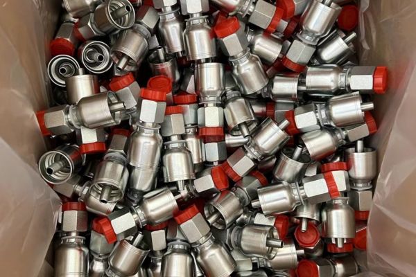
crimp Fitting stock

Separate Dispatch, Port Arrival, and Stock Availability

“Delivery next month” is too vague to support a replenishment decision unless the event and destination are defined. Dispatch may refer to collection from the origin location, while ETD and ETA normally describe estimated departure and arrival for a named transport leg; none automatically represents receipt at your warehouse.

Set a Required Usable-Stock Date

For recurring replenishment, establish when the remaining approved stock is expected to stop covering demand, taking existing allocations and confirmed incoming quantities into account. For planned maintenance or equipment work, identify when parts must be available for preparation and assembly, which may be earlier than the date work starts on the machine. Keep that required date separate from the latest forecast arrival, because moving the forecast should reveal a supply gap rather than automatically move the operational requirement.

Work Backward Through the Complete Replenishment Interval

Include every stage that must finish before the fittings can be used.

Build the Timeline From Its Dependencies

Begin at the required usable-stock date and work backward through receiving, local distribution, destination processing, main transport, origin handling, and order readiness. Include specification approval and the internal time needed to authorize and release the order, since a request sitting in an approval queue has not started replenishment. Add sequential stages together, but avoid adding tasks that genuinely run in parallel as though each had to finish before the next could begin.

Use Comparable Completed Orders as Evidence

Historical timing is useful when it comes from completed shipments with similar origins, routes, shipment types, destinations, and receiving arrangements. Measure from the actual start event to the actual end event, preserving abnormal delays as labeled exceptions rather than silently deleting them or making them the normal expectation. A quotation’s preparation interval should not replace observed order-to-readiness time when it excludes approvals or conditions, and a port-to-port transit estimate should not replace warehouse-to-warehouse replenishment time.

Build the planning timeline with these checks:

Connect Reorder Timing to Demand and Inventory Position

Order when expected replenishment can still cover the demand ahead.

Calculate the Trigger Using Consistent Units

For regular consumption under continuous inventory review, a starting reorder point is expected demand over usable replenishment lead time plus a justified safety-stock allowance. Use the same time unit for demand and lead time, then compare the trigger with inventory position: usable on-hand stock plus confirmed incoming quantities, less allocations and outstanding demand, without counting the same commitment twice. If reviews happen periodically, include the interval until the next review in the protection horizon, because a part that falls below its trigger just after a review may wait before anyone acts. This approach connects the ordering decision to actual stock exposure rather than relying on a fixed monthly buying date.

Treat Incoming Stock According to Its Timing

An open order can improve the inventory position while still arriving too late to prevent a shortage, so check projected availability by date as well as the total quantity. Separate confirmed scheduled demand from ordinary consumption forecasts, and prevent a known maintenance requirement from being counted both as an allocation and again inside a forecast. For irregular parts, a low daily average can hide a sudden job requirement; use identified work and interruption consequences when deciding whether a reserve is justified.

Resolve Fitting Specifications Before the Shipping Clock Starts

A timely receipt counts as replenishment only if the fittings match the approved requirement.

Check the Connection and Physical Configuration

An order description should distinguish thread form, connection standard, sealing method, connection gender, size, and fitting geometry, with material and finish included where specified. A straight fitting and an elbow can share a thread designation while fitting very different installation spaces, and a hose-end connection size does not necessarily equal the hose bore. Follow a structured hydraulic fitting identification process, using dimensions, pitch, and sealing-face information to resolve uncertain items before order approval.

Packing fittings

Verify the Hose Attachment and Assembly Requirements

For crimped hose ends, match the fitting series to the exact hose construction and size, with applicable assembly data and compatible tooling confirmed before the part is treated as an approved reorder. A one-piece fitting can reduce separate ferrule selection because its stem and sleeve are preassembled or secured together; a two-piece system requires the correct separate components. If your stock uses two-piece assemblies, verify the specified hydraulic ferrule alongside the stem, because receiving only one component does not provide a complete usable combination. Product-specific instructions govern preparation, insertion, dies, and crimp dimensions, so an unavailable approved part cannot be replaced merely by choosing another item with the same dash size.

Before releasing a technically uncertain line, obtain:

Track Shipping Milestones Without Turning Forecasts Into Promises

Update the plan when evidence changes, while preserving the original requirement.

Tie Every Status to an Event and a Source

A booking request, confirmed booking, completed collection, and actual departure are different events, and the status record should make that distinction visible. Store the current forecast date, its source, the time of the update, and any unresolved condition so an old estimate is not reused after the route or departure changes. Check the shipment’s own booking and movement information, since a general market notice can prompt a review but cannot establish that your particular order is delayed.

Keep Transport Responsibilities Visible

The agreed trade term and named place help define who arranges particular movements and documents, but they do not replace a complete inventory availability timeline. Confirm which party provides the booking information, who coordinates destination release, and who communicates changes to the receiving location, especially when separate organizations control different stages. Add handoff dates and unresolved dependencies to the record so the next owner can act before a missed instruction or document affects movement.

Use Buffers and Split Shipments Selectively

Address the specific uncertainty or shortage instead of extending every order equally.

Choose a Buffer With a Recorded Reason

A planning buffer should reflect uncertainty in the relevant stage, such as variable demand, inconsistent readiness, route disruption, or destination processing, and should be reconsidered when that uncertainty changes. Avoid quietly adding a reserve at every stage and another large reserve at the end without checking whether the same risk has been counted repeatedly. Stock reserves and time allowances can both affect shortage exposure, but they need to be assessed together so extra days and extra units do not create unintended overstock.

Evaluate a Partial Shipment by What It Can Complete

A split shipment makes sense only when the early quantities address a real requirement and the added costs are justified by that benefit. For illustration, if a scheduled group of hose assemblies needs two approved end fittings, shipping one end early provides little immediate value when the other end will arrive after the work date. Identify the complete set of components needed for the affected work, then compare consolidated delivery, a focused partial shipment, transfer of approved stock, and any separately validated transport option. Include additional freight, handling, destination processing, and receiving effort in the comparison, rather than treating an earlier departure as proof that the split is worthwhile.

Prepare the Next Reorder Around Usable Availability

Make the technical requirement and timing assumptions reviewable before committing the order.

Create One Record for Each Affected SKU

Give every line its approved identity, quantity, current usable stock, committed demand, expected receipt, and required availability date, with a separate note for unresolved technical or transport questions. Add the full destination and the meaning of the requested date, because “needed by Friday” can refer to warehouse receipt, assembly preparation, or installation and therefore lead to different actions. If an alternative is proposed to close a shortage, retain it as a separate approval decision; application suitability includes pressure, temperature, fluid, and assembly limits, with the lowest applicable component rating governing the hose assembly. Follow the equipment safety procedure when identification requires removal, including pressure and stored-energy release, and never search for pinhole leakage with a hand.

For the next timing review, prepare:

Reorder Against the Whole Interval

The right time to reorder hydraulic fittings depends on when approved parts must be available and how long the complete replenishment process actually takes; a favorable unit price cannot offset an incorrect connection, and an early dispatch cannot compensate for unresolved customs arrangements or fittings held at receiving. Start with verified stock and demand and work backward from usable availability, and distinguish confirmed events from changing forecasts, apply buffers where evidence supports them, and evaluate expediting only for the components that will close an identified gap; before releasing the next order, prepare the approved SKU list, quantities, destination, required stock date, and current readiness and transport assumptions, since that information creates a schedule you can update when conditions change without losing sight of the original operational need.

FAQ

Can a reorder still be late if the goods ship on the promised date?

Yes, because the promised event may cover dispatch only. Main transport, destination processing, local delivery, and receiving can still place usable availability after the required date.

Should all low-stock fittings move by air?

No; evaluate the actual shortage, complete component requirements, feasible arrival, and total additional cost. Parts that will not enable needed work may provide little benefit from faster transport.

Should you hold an entire order for one unresolved SKU?

Separate the unresolved line when the order and transport arrangements permit it, then evaluate the remaining quantities against their own requirements. Do not release that line under an assumed specification merely to keep the shipment together.

What if only part of the shipment passes receiving checks?

Post only the accepted quantity as usable inventory and keep the held quantity separately visible. Recalculate the remaining requirement by SKU rather than marking the complete order available.

How should a previous delay affect the next reorder?

Review its cause before changing the next timeline. A recurring process constraint may justify an adjustment, while a documented one-time event should remain visible without automatically becoming the normal lead time.

How to Plan Hydraulic Fitting Replenishment Across Branches

How to Plan Hydraulic Fitting Replenishment Across Branches?

Plan hydraulic fitting replenishment by identifying what each branch actually uses, standardizing part records, and setting replenishment rules around demand and the time needed to receive usable stock. A shared catalog alone cannot tell you whether the right connection, hose fitting series, or elbow is available where the next job will happen. One location may hold excess straight fittings while another cannot complete an assembly because its required swivel is missing. The goal is to make approved parts available at the correct location without filling every shelf with the entire product range or treating similar-looking fittings as interchangeable.

Start With Local Demand, Then Build a Shared Stock Plan

Use branch-level consumption to decide placement, and network-level information to coordinate replenishment.

Separate Completed Work From Unfilled Requests

Sales and assembly records show what left the shelf, but they do not reveal every request that could not be filled. Record missing part numbers, jobs postponed for unavailable connections, and requests fulfilled through transfers, then separate recurring demand from one-time projects that would distort a normal replenishment pattern. Check these records against the equipment serviced locally and upcoming maintenance periods, because a branch supporting agricultural machinery can have a different demand pattern from one handling industrial maintenance. A full catalog shows possible combinations; a useful stock plan identifies which approved combinations repeatedly support actual work.

Packing and stock

Classify Parts by Use and Consequence

A frequently used fitting usually deserves a different policy from an unusual elbow ordered for one machine, yet frequency alone should not determine priority. A low-volume part can warrant a reserve when its absence prevents an important assembly from being completed and no approved alternative is readily available. Classify each SKU by demand regularity, interruption consequence, replenishment difficulty, and availability elsewhere in the network before deciding its stocking location.

Give Every Fitting a Consistent, Verifiable Identity

Create one controlled part record before combining quantities across branches.

Define the SKU Beyond Its Thread Name

Descriptions such as “half-inch female elbow” leave too much unresolved for reliable purchasing or picking. Use a hydraulic fitting identification guide to record the connection family, thread size and pitch, gender, seal, configuration, and material, plus the manufacturer and series where these determine hose compatibility. For hose ends, keep hose size separate from connection size, since a single fitting may combine different sizes at its two ends.

Keep Similar Connections and Unapproved Alternatives Separate

Two fittings with similar threads can require different sealing faces, and parts with matching connection ends can have different hose attachment requirements. A one-piece hose fitting combines or secures its stem and ferrule beforehand, reducing separate sleeve selection; it does not establish compatibility with every hose of the same nominal size. Keep different series and unapproved alternatives in separate records and bins, because convenience at the picking stage cannot justify an uncertain assembly combination.

Use these fields as the minimum working identity for each relevant SKU:

Set Reorder Points Around Usable Replenishment Time

Trigger replenishment before expected consumption exhausts usable stock.

Distinguish the Trigger From the Reserve

A reorder point is the inventory position at which you start replenishment, while safety stock is a reserve intended to cover defined uncertainty in demand or replenishment time. For reasonably regular consumption under continuous review, a starting model is expected demand during replenishment lead time plus safety stock, using consistent time units and checking the result against observed shortages and surplus. Inventory position should include usable stock and confirmed incoming quantities, less allocations and outstanding demand, with double-counting prevented by the inventory system.

Allow for Review Frequency and Irregular Demand

If stock is reviewed only periodically, the planning horizon must cover both the replenishment interval and the time until the next review; a continuous-review trigger cannot simply be copied into that process. Use the time from an authorized order to accepted, available inventory, including receiving checks and internal distribution, rather than only a quoted dispatch interval. Intermittent demand needs separate treatment because an average can conceal long quiet periods followed by a specific maintenance requirement, and a low average does not establish that zero reserve is appropriate. Scheduled work, seasonal changes, and unusual projects should therefore be visible adjustments, with a recorded reason and a date for reconsidering them.

Decide What Stays Local and What Can Be Shared

Shared inventory is useful only when the receiving branch can obtain and use it in time.

Compare Local Holding With Central Availability

Keep recurring parts close to the work when repeated transfers would create avoidable waiting, handling, and transport expense. Central stock may suit some low-frequency parts, but the decision depends on transfer time, operating hours, transport availability, and whether another branch has already committed the same quantity to a job. A network total can therefore overstate availability: a part on another shelf may be reserved, awaiting identification, or too far away to meet the requirement. Compare the cost of local holding with the consequence of waiting, and avoid describing centralized stock as immediately available unless the transfer arrangements support that claim.

Control Transfers as Carefully as Purchases

A transfer should reduce one branch’s available quantity and create a traceable incoming quantity at the receiving location, with its arrival and acceptance recorded. Keep the source part number, approved series, lot information where required, and connection description attached to the movement so a loose fitting does not become an unidentified item on arrival. For two-piece assemblies, verify that the required stem and compatible hydraulic ferrule are both available in their approved combination, rather than moving a sleeve that merely looks suitable. Count transfer demand separately from final consumption, or the same fitting can appear to have been used once at the sending branch and again at the receiving branch.

Before authorizing a transfer, confirm:

Compare Total Replenishment Cost Without Hiding Errors

Evaluate purchasing, handling, and shortage consequences alongside unit price.

43 series crimp fittings protection

Capture Costs That the Invoice Does Not Explain

A lower unit price can be outweighed by repeat freight charges, extra sorting, wrong-item returns, blocked inventory, and assemblies that must be remade after incorrect parts were selected. Track these costs against their causes rather than assigning an unsupported percentage to every order or assuming that all inexpensive fittings create problems. Record a transfer’s transport and handling separately, identify whether a shortage actually postponed work, and distinguish documented internal costs from estimated consequences that require further evidence. Comparing orders on the same scope, specification, delivered quantity, and cost basis makes the result more useful than treating the cheapest quoted line as the least expensive replenishment option.

Investigate Why Stockouts and Surplus Occur Together

A shortage of one SKU alongside excess of another often calls for a record or allocation review before an increase in purchasing. Check for duplicate identifiers, pack-versus-piece errors, unposted transfers, quantities assigned to the wrong branch, and substitute items that were received under the original part number without approval. Also distinguish a genuine rise in demand from stock that exists physically but remains unavailable because of damaged threads, missing identification, or pending technical review.

Test the Process Before Expanding the Stock Range

Start with a defined group of parts whose demand and specifications you can verify.

Choose a Pilot That Reveals Process Problems

Select a manageable group of recurring SKUs and participating branches based on available records, then document their starting quantities, current approval status, replenishment times, and known identification problems. The pilot should test the inventory process using approved products, rather than quietly introducing unfamiliar fitting alternatives under existing stock numbers. Track availability at the time of request, unfilled demand, transfer frequency, picking corrections, and excess that remains after expected work is completed. Choose the review period around the relevant replenishment and consumption cycles, because an arbitrary calendar interval may end before a normal receipt or seasonal requirement provides meaningful evidence.

Expand Only When the Evidence Supports It

Compare pilot results with the starting condition and examine whether the change came from better replenishment or from temporarily carrying more stock. Expansion is justified when records are reliable, receipts are usable, recurring demand supports the additional variants, and the network can maintain the same identification discipline across more locations. If shortages persist, check the assumed lead time and recorded lost demand; if surplus grows, revisit project quantities, branch allocations, and demand assumptions before adding more SKUs.

Prepare a Replenishment List That Can Be Checked

Resolve technical uncertainty before treating an item as routine replenishment.

Confirm the Part and the Conditions of Use

For hose ends, approval must cover the exact hose, fitting, and assembly procedure, including the applicable crimper and tooling; nominal size alone is insufficient. Pressure, temperature, fluid compatibility, and application limits also require the relevant component data, with a hose assembly limited by its lowest applicable rated component. The manufacturer’s hose safety guide illustrates why selection and assembly require product-specific instructions; if identification requires removing an installed assembly, shut down, isolate and release hydraulic pressure and stored energy under the equipment procedure; never use a hand to search for a pinhole leak.

Prepare the following information before the next replenishment review:

Make the Next Order Support the Next Job

Hydraulic fitting replenishment works when stock records describe parts that people can identify, locate, and use in approved applications; buying every catalog option cannot compensate for uncertain thread identification, missing hose compatibility records, or quantities that are invisible between branches, so before adding inventory, establish which recurring jobs are being delayed, which approved items those jobs require, and how long replenishment takes to become usable stock, then assign local and shared quantities, verify the reorder rules, and review actual results after normal replenishment cycles. Correct matching matters more than a low unit price or a close visual resemblance because an unusable fitting does not restore availability; start the next review with verified part records, branch demand, open-order dates, and clearly identified exceptions.

FAQ

Should inventory turnover be measured in pieces or value?

Use a consistent financial basis for financial turnover, commonly cost of goods sold divided by average inventory value over the same period. Piece movement is useful for individual SKU planning, but adding unlike parts together can hide a slow-moving expensive item.

How should stock on a service vehicle be recorded?

Treat each vehicle as a separate inventory location with recorded issues, returns, and replenishment. A part loaded onto a vehicle has moved location; it has not necessarily been consumed on a completed job.

Can returned fittings go directly back into available stock?

Only return parts to available stock after identity, condition, and traceability requirements have been checked. Used, previously crimped, damaged, or uncertain components require separate disposition under the applicable product instructions.

How do you plan inventory for a new branch without usage history?

Begin with verified equipment and service requirements, supported by comparable branch records where appropriate. Treat initial quantities as provisional and review actual consumption and unfilled requests before expanding them.

Should different finishes share one stock number?

Use separate identities when finish is a specified requirement or affects approval for the application. A controlled grouping may support reporting, but it must not erase differences that matter when parts are picked.

How to Identify Worn Crimp Dies in One-Piece Hose Assemblies

How to Identify Worn Crimp Dies in One-Piece Hose Assemblies?

Repeated crimps that develop uneven flats, unusual marks, asymmetry, or changing measurements indicate a process problem, but they do not prove the dies are worn. Worn crimp dies can affect one-piece hose assemblies by changing how compression is distributed around the ferrule, yet incorrect setup, debris, poor die seating, measurement error, hose variation, or damaged components can create similar symptoms. A sound investigation starts by containing the affected work, documenting the pattern, and testing competing causes against evidence. It does not keep suspect dies in use or assign a wear limit without an approved tooling procedure.

Begin with the Pattern, Not a Presumed Cause

The first task is to describe what changed. A conclusion such as “the dies are worn” is premature until the team knows when the variation began, which configurations are affected, and whether the evidence follows the tooling.

Describe the observable symptoms

Record actual measurements, measurement positions, ferrule appearance, die marks, and any asymmetry around the circumference. Note whether the condition appears on one segment, repeats at the same angular position, changes between cycles, or affects only one hose-and-fitting combination. Photograph parts under consistent lighting when the quality system permits, while preserving their identity and sequence.

Do not classify every out-of-round result as die wear. A shifted hose, cocked fitting, incorrect die set, loose tooling, contamination, instrument error, or ferrule variation may produce a profile that resembles worn tooling. The observation should remain neutral: for example, “one flat is wider and readings vary by position,” not “die segment is worn.”

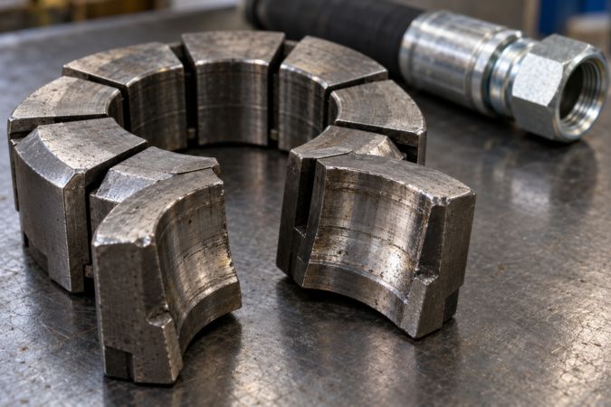
Worn hydraulic hose crimper dies

Establish the last known accepted state

Identify the last accepted tooling check, first-piece approval, or verified production result. Record the machine, die set, setup program, hose and fitting codes, instruction revision, operator or station, and measurement device. This reference helps define the trace-back window without inventing a fixed number of cycles.

If the symptom involves an installed hydraulic assembly, stop the equipment, isolate the system, release pressure and stored energy, secure raised loads, and follow lockout and manufacturer instructions before inspection. Never touch a suspected high-pressure leak or use a questionable assembly for diagnosis.

Contain Tooling, Product, and Records

Containment prevents uncertain tooling from creating more uncertain product. It also preserves evidence before cleaning, adjustment, or replacement changes the condition being investigated.

Stop and identify the scope

Take the suspect die set and related tooling out of service under the shop’s hold procedure. Label the machine setup so another operator cannot resume it. Segregate the current first piece, in-process assemblies, and finished assemblies produced since the last accepted check or other justified trace point.

The trace-back scope should consider:

Do not automatically scrap everything in the window, and do not release it merely because most pieces look normal. Place it on hold until a qualified review defines the applicable inspection, test, or disposition.

Preserve the as-found condition

Record die orientation, segment locations, seating, contamination, damage, and machine setup before disassembly or cleaning. Mark segment positions through an approved non-damaging method if the investigation needs to correlate a tool location with a ferrule feature. Preserve programs, settings, and instruction revisions used for the affected work.

Cleaning may be necessary later, but immediate cleaning can erase evidence of trapped debris, corrosion product, or uneven seating. Capture the as-found state first, then follow the approved inspection process.

Separate Die Wear from Setup and Component Variation

Fault isolation compares plausible causes rather than making one favored cause fit every observation. Change one controlled factor at a time where the approved investigation procedure allows.

Check setup and identity

Verify the exact hose manufacturer, hose series, size, fitting code, and approved crimp instruction. Confirm the machine, die set, adapters, program, and revision against the traveler. Matching dash sizes do not prove hose-and-fitting compatibility, and an incorrect die can be installed even when its external shape resembles the expected set.

Review hose preparation, insertion position, and fitting alignment. If only one assembly family shows the problem, compare its preparation and component records before blaming tooling used successfully on other approved configurations. If every configuration on the same die position shows a similar angular symptom, tooling or seating becomes a stronger hypothesis, but still requires inspection.

Check normal and abnormal component variation

Compare hose and fitting identities, lots, and dimensional inspection records within the approved system. A changed hose outside diameter, ferrule condition, mixed fitting code, or damaged part can influence the finished profile. Do not invent allowable component ranges; use current drawings, incoming inspection criteria, and manufacturer data.

Ask whether the symptom tracks the die set, the machine, the component lot, the operator method, or the measurement device. Evidence that moves with one factor is more persuasive than a general association with repeated production.

Read Surface Evidence Without Overclaiming

Uneven flats, marks, and asymmetry can guide the investigation, but surface appearance is screening evidence. It cannot alone establish tooling wear or assembly acceptance.

Correlate marks with die positions

Compare repeated ferrule marks with the recorded orientation of die segments. A recurring feature at the same tooling position may indicate damage, contamination, or seating trouble in that area. A feature that rotates with the part or appears randomly may point toward loading, component, or measurement variation instead.

Look for localized scoring, burr transfer, inconsistent flat width, unexpected ridges, or incomplete closure patterns. Record whether the feature appears before or after cleaning and whether it is present on a known reference piece. Do not polish, grind, stone, or otherwise alter tooling unless an approved repair procedure and qualified authority permit it.

Distinguish cosmetic evidence from functional evidence

A visible mark is not automatically a reject, and a smooth-looking ferrule is not automatically acceptable. Evaluate the part against the controlled visual and dimensional criteria for the exact assembly. If the procedure requires further test or engineering review, appearance cannot waive that requirement.

Pressure suitability and performance depend on the complete hose assembly, including the hose, fitting, preparation, crimp process, and application conditions. Tooling appearance cannot establish those properties.

Inspect Die Seating, Cleanliness, and Condition

Die condition includes more than gradual wear. Incorrect seating, foreign material, corrosion, segment damage, and mismatched pieces can all change the compression profile.

Examine the complete tool stack

Inspect the die segments, master die or bowl, adapters, retainers, and seating surfaces identified by the equipment procedure. Confirm that all segments belong to the same controlled set and that identification is legible. Look for chips, cracks, damaged edges, fretting, unusual contact areas, or segment movement that differs from the expected condition.

Clean only after the as-found record is complete, using the approved method. Reinspect the seating faces and working surfaces under suitable lighting. If a condition cannot be judged reliably, keep the tooling quarantined for qualified assessment rather than returning it to service based on a quick visual check.

Crimping Compatibility & Safety Reminder

Avoid invented wear thresholds

There is no responsible universal statement that a die is acceptable for a certain number of cycles or until a particular visible amount of wear occurs. Allowable condition and replacement criteria depend on the equipment maker, tooling design, controlled maintenance program, and process capability evidence.

Do not continue using suspect dies because an average measurement remains within a target. Localized compression can be uneven even when one calculated value appears acceptable, and the approved method may require multiple positions or other profile checks.

Repeat Measurements with a Controlled Method

Measurement repeatability must be established before numerical variation is attributed to tooling. The same part measured differently can create a false trend.

Verify the instrument and technique

Confirm the device identity, calibration status, resolution, cleanliness, and zero or reference check required by the procedure. Use the specified measurement locations and avoid seams, flash, raised marks, or other excluded features. Hold the instrument consistently without excessive force or angular misalignment.

Repeat the measurement as the approved instruction requires, recording individual readings rather than only an average. Have a second qualified person repeat the method when the quality procedure calls for verification. If results differ materially by operator or technique, resolve the measurement system before adjusting the crimper or condemning the dies.

Compare evidence across controlled samples

Where the approved investigation permits, compare the affected result with a known accepted reference, a verified die set, or another controlled machine while changing only one factor. Do not create production assemblies from an unapproved combination merely for comparison. Any trial pieces remain identified and segregated until their disposition is recorded.

A symptom that follows the suspect die set under controlled conditions strengthens the tooling hypothesis. A symptom that remains with the machine, component lot, or measurement device points elsewhere. The goal is causal evidence, not a convenient explanation.

Decide on Tooling Inspection or Replacement

Only a qualified assessment under the approved procedure should release, repair, or replace suspect tooling. Operators should not create their own wear limits or repair methods.

Use cause–evidence–decision logic

The table does not define acceptance limits. It connects each hypothesis to the evidence needed before a disposition is made.

Requalify the setup after action

After approved cleaning, repair, replacement, or setup correction, repeat the required machine checks and first-piece inspection. Record the new tooling identity or maintenance action, actual measurements, visual results, and approval. Do not assume a replacement die recreates the prior setup without verification.

Trace and Disposition Affected Assemblies

Correcting the tool does not resolve product already made. The team must determine which assemblies could be affected and what evidence is needed for release, additional evaluation, or rejection.

Define the review window

Use the last accepted check, maintenance record, tooling event, measurement trend, and production traceability to establish a technically justified window. Include jobs that used the suspect configuration, not unrelated work merely because it occurred on the same day. Expand the scope when evidence shows the condition may have begun earlier.

For each held group, record hose and fitting identities, lots, production time or sequence, machine, tooling, program, inspection results, and the relationship to the observed fault. Do not rely on memory or reconstruct identifiers after labels have been lost.

Authorize disposition

Release, additional inspection, test, rework, or scrap decisions must follow the approved quality system and qualified technical review. Do not re-crimp or reuse a questionable hose assembly without a validated procedure. A passed sample does not automatically approve every unit in a variable population.

Conclusion

Inconsistent crimp profiles require containment and disciplined fault isolation, not an immediate claim that the dies are worn. Record the pattern, preserve the as-found setup, and trace product back to the last accepted evidence. Then compare tooling condition and seating with setup identity, hose and fitting variation, insertion, machine status, and measurement repeatability. Surface marks and asymmetry can focus the investigation, but a qualified assessment must determine whether a die is worn, damaged, repairable, or suitable for return to service. After any approved action, repeat first-piece release and document the result. This evidence-based approach to worn crimp dies in one-piece hose assemblies protects both the current process and assemblies already produced.

Frequently Asked Questions

Does an out-of-round crimp always mean the dies are worn?

No, setup, seating, contamination, component variation, loading, and measurement technique can create similar results. Isolate the cause with controlled evidence before replacing tooling.

Can dies stay in service if the average diameter is acceptable?

Not automatically, because an average may hide local variation or an abnormal profile. Follow the approved multi-position measurement and tooling-condition criteria, and quarantine suspect dies for assessment.

Should a damaged die segment be replaced by itself?

Only if the tooling manufacturer and approved maintenance procedure permit that action. Some sets require controlled matching or complete-set replacement, so do not improvise the repair.

How far back should affected assemblies be traced?

Use the last accepted check and available production, maintenance, and measurement evidence to define the window. There is no universal number of cycles that fits every process.

Can held assemblies be re-crimped after the dies are replaced?

Only under an approved, validated disposition that specifically permits re-crimping for that assembly. Otherwise, keep them segregated for qualified review, testing, rejection, or other authorized action.

How to Select 71 Series One-Piece Fittings for Replacement

How to Select 71 Series One-Piece Fittings for Replacement?

An old hydraulic hose can provide useful clues for ordering a replacement, but it rarely tells the whole story. The hose marking may be worn, the fitting number may be partly hidden, and the original assembly may have been modified during an earlier repair.

For assemblies using 71 series one-piece fittings, the replacement needs to preserve the equipment connection while matching the hose and assembly process. Copying the visible thread or ferrule shape is not enough.

What Makes a 71 Series Fitting a One-Piece Fitting?

The stem and ferrule are supplied together

A 71 series one-piece fitting is a permanent crimp hose fitting with the stem and ferrule preassembled. The assembler does not need to choose a separate loose ferrule before making the hose assembly.

“One-piece” describes this supplied arrangement. It does not mean that the stem, nut, and ferrule are necessarily machined from one solid piece of metal.

The arrangement simplifies component handling, but it does not eliminate the need for correct hose selection. The hose-side geometry and the specified crimp process must suit the exact hose being assembled.

71 series Hydraulic Crimp Fitting

The crimped connection is permanent

During assembly, the ferrule is compressed around the hose using the prescribed equipment and tooling.

The fitting should therefore be treated as a permanent connection, rather than a reusable hose end. A fitting cut from an old assembly should not be assumed suitable for another crimp.

For replacement work, use the old fitting to help identify the required configuration, then specify new components for the new assembly. Visible condition alone cannot establish whether a previously crimped fitting remains suitable for reuse.

Read the Old Hose Before Ordering New Fittings

Capture the full hose marking

Before discarding the old hose, photograph any readable layline information. Record the manufacturer, complete hose model, nominal inside diameter, and other relevant markings.

Published references associate the 71 series with specified hoses, including 721, 721TC, and 721ST within applicable catalog scopes. These names are useful identification leads, but they do not replace a size-specific compatibility check.

Keep suffixes intact. A shortened description such as “721 hose” may omit information needed to locate the correct product and assembly instructions.

Where the reference comes from an older catalog, confirm the current replacement requirements rather than assuming the original combination remains unchanged.

Know what measurements cannot tell you

Measuring the inside or outside diameter can help narrow an investigation. It cannot reliably reconstruct an unknown hose model.

Hoses with the same nominal inside diameter may differ in cover thickness, reinforcement, and response to crimping. An old hose may also be swollen, flattened, abraded, or otherwise altered by service.

If the marking is unreadable, look for equipment records, previous purchase orders, assembly tags, or a documented parts list.

When the original hose cannot be established, specify a suitable new hose and confirm its approved fitting combination. Do not base the new assembly on an assumed identity.

Separate the Hose-Side Match from the Equipment Connection

Two interfaces must be correct

A hose fitting connects two different interfaces: the hose on one side and the equipment connection on the other.

Matching the equipment end does not prove that the fitting is suitable for the selected hose. Equally, a fitting approved for the hose may have the wrong thread, seat, or flange for the machine.

Keep these questions separate when reviewing a replacement:

This distinction helps avoid a common mistake: approving a fitting because it screws onto the equipment, then choosing a hose that happens to fit inside it.

Identify the sealing surface, not just the thread

Record the connection standard, male or female form, thread diameter, and pitch. Then identify where the seal is made.

Depending on the connection, sealing may occur at a cone, a flat face with an O-ring, a port seal, or a specified tapered-thread interface.

A nut that turns onto the mating thread may still have the wrong seat or sealing arrangement. Do not tighten a questionable connection to find out whether it seals.

For flange connections, confirm the complete flange form and mating dimensions. A photograph can help identify a candidate, but dimensional confirmation remains necessary.

Copy the Installation Requirements, Not the Old Hose’s Shape

Measure length using an agreed reference

An old hose often retains a curve after removal. That shape should not be used as the primary length specification.

Agree on the measurement reference for the new assembly. Depending on the end configurations, this may use defined sealing faces, fitting centerlines, or other drawing references.

Record the required finished length clearly. Avoid giving only an approximate cut-hose length when the supplier is expected to deliver a complete assembly.

Also consider whether the old hose was correctly sized. Evidence of stretching, excessive slack, tight bending, or rubbing may indicate that its length should be reviewed rather than copied.

Record elbow dimensions and relative orientation

“90-degree elbow” does not fully describe an angled fitting.

Installation length and elbow drop affect clearance and hose exit direction. Two fittings with the same nominal angle can position the hose differently.

Where both ends are angled, specify their relative orientation using an agreed drawing or measurement convention. Descriptions such as “the elbows face roughly the same way” are difficult to reproduce accurately.

Check that the finished assembly can be installed without twisting the hose, pulling it tight, or forcing a bend immediately behind the ferrule.

Decide Whether to Retain or Change the Hose Specification

Retaining the hose still requires a current check

When the existing hose is identifiable and remains suitable for the application, keeping the same specification may simplify the replacement.

Even so, confirm the fitting combination and current assembly data. An old purchase record may identify what was previously supplied without proving that it was correct.

Review the reason for replacement as well. A hose damaged by abrasion may need improved routing or protection. A recurring leak may require inspection of the mating connection.

Replacing parts without addressing the cause can reproduce the same problem.

A new hose creates a new assembly combination

Changing the hose manufacturer or model is more than a purchasing substitution.

The new hose may have the same inside diameter and pressure marking while requiring a different fitting family or crimp process.

Confirm the proposed hose and fitting together. If the new hose requires another fitting family, preserve the equipment connection and installation dimensions through an appropriate configuration.

There is no benefit in retaining a 71 series designation when the selected hose requires a different approved assembly system. The objective is a suitable replacement assembly.

Check the Workshop Can Assemble the Combination

Obtain the applicable preparation instructions

Before cutting the new hose, confirm the preparation and insertion requirements.

Where no-skive assembly is approved, the outer cover does not need to be removed. That instruction applies to the specified combination, rather than every hose that can enter the ferrule.

Cut quality, cleanliness, and insertion still matter. An uneven end or incomplete insertion can affect the assembly even when the final crimp measurement appears acceptable.

Use the required insertion reference and external marking method so that positioning can be checked before crimping.

71 series

Use the correct tooling and measurement method

The assembly instructions should identify the hose, fitting, size, machine or process basis, tooling, target crimp dimensions, tolerance, and measuring location.

Do not borrow a die or crimp value from another series because its ferrule looks similar. Nominal hose size does not establish a common finished crimp diameter.

Before repeating production, inspect the first assembly. Confirm the components, insertion, crimp measurements, length, and orientation, together with any required testing.

A dimensional result is one part of the inspection. It cannot independently establish compatibility or suitability for the application.

Review the Conditions That Caused the Replacement

Pressure, temperature, and fluid remain part of the decision

The 71 series designation does not provide a universal assembly pressure or temperature rating.

Confirm normal working pressure, relevant pressure peaks, fluid, and operating temperature. The hose, fittings, seals, and approved combination must all suit those conditions.

Do not assign the hose’s pressure rating to the entire assembly without checking the other components. Likewise, a metal fitting does not establish fluid compatibility for the hose tube or seals.

Where the service conditions have changed since the original installation, review the replacement against the current requirements.

Look for mechanical causes of early failure

Inspect the route for rubbing, sharp edges, heat exposure, excessive movement, and connection loading.

Repeated damage near the fitting may indicate a routing or support problem rather than a need for a heavier-looking fitting.

Consider whether the hose has sufficient room to move through the equipment’s operating range. Check access for installation and future inspection.

Before removing or examining an installed assembly, isolate the equipment, release hydraulic pressure and stored energy, and follow the equipment’s safety procedure.

Give the Supplier a Replacement Specification They Can Use

Provide a concise identification package

A clear inquiry reduces the chance of receiving a visually similar but unsuitable fitting.

Include:

Measurements should support the photographs. A close-up image of a thread alone rarely provides enough information for accurate identification.

Keep the accepted details for the next repair

Once the replacement is confirmed, retain its hose model, fitting numbers, length, orientation, and assembly reference.

Give the assembly a clear internal identifier where practical. This makes the next order easier to reproduce and reduces dependence on a damaged sample.

If a supplier later proposes a change, compare it against the retained specification. Record accepted changes so that future orders follow the updated configuration.

A short, accurate record is more useful than repeatedly starting identification from scratch.

Conclusion

Replacing an assembly with 71 series one-piece fittings starts with identifying the hose and the equipment connections separately.

Preserve complete hose markings, confirm the sealing interface, and define the length and elbow geometry needed for installation. If the hose specification changes, reassess the fitting combination and assembly process.

Finally, address the reason the old assembly failed and retain the accepted replacement details. This helps turn a one-time repair into a repeatable specification for future maintenance.

Frequently Asked Questions

Can I identify a 71 series fitting from its ferrule shape?

Ferrule shape may provide a clue, but it cannot reliably establish the series or exact configuration. Use readable part numbers, drawings, and the hose information.

Can a 71 series fitting be used on any hose with the same inside diameter?

No. Compatibility depends on the exact hose model, size, fitting, and approved assembly process.

Should I copy the length of the old hose exactly?

First check whether the old length was suitable. Then specify the replacement using an agreed measurement reference, accounting for routing and movement.

Can a fitting from an old assembly be crimped onto a new hose?

Treat the connection as permanent and specify new approved components. Do not assume a previously crimped fitting is suitable for reuse.

What if the original hose model is no longer available?

Select a suitable current hose and confirm its fitting and assembly requirements. Preserve the equipment interface and installation dimensions without assuming the original fitting family must remain.

Contact Topa

Save 30% on maintenance costs with our easy-install hydraulic fittings. Contact Now!