How to Prevent Mix-Ups When Crimping One-Piece Fittings

How to Prevent Mix-Ups When Crimping One-Piece Fittings?

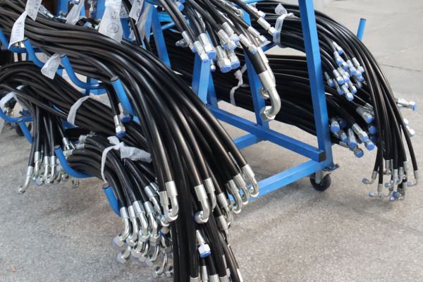
When crimping one-piece fittings, switching to a new SKU takes more than changing dies or selecting a machine program. A leftover fitting, an outdated work order, or a setting carried over from the previous job can cause errors in the next batch. Before restarting production, clear the work area, confirm the exact hose-and-fitting combination, verify the approved setup, and inspect and release the first assembly. Clear checkpoints before, during, and after each changeover help prevent mix-ups and keep every batch traceable.

Close the Previous Run Before Opening the Next

The safest transition starts by treating the end of the current order as a controlled production event. The next SKU should not enter the work area while usable parts, rejects, labels, paperwork, or program information from the previous run remain active.

Reconcile parts and work in process

Count or otherwise reconcile the completed assemblies, unused hose, unused fittings, rejected pieces, setup pieces, and any loose components according to the shop’s approved procedure. Return accepted unused stock to its identified location only after confirming the container and label match the parts. Place questionable, damaged, or unidentified pieces in a hold location; never drop them into a convenient bin because they look similar.

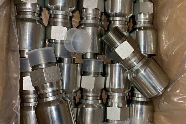
One-piece construction can reduce separate ferrule picking, but it does not eliminate mixing risk. Two fittings may have similar plated bodies and retained ferrules while differing in hose-side geometry, connection, dash size, angle, or approved crimp data. A loose fitting without reliable identity must not cross into the next job.
Mixed SKU Packing

Clear the physical and digital line

Inspect the crimper table, die storage area, measuring station, hose-cutting area, bins, floor, scrap container, label printer, and any transfer tray used between operations. Remove the prior traveler, tags, samples, drawings, and handwritten settings. Close or sign out of the prior machine program according to the equipment procedure so that its values cannot silently remain in use.

Line clearance should be recorded, not assumed. A second-person or electronic confirmation may be required by the local quality plan. The person signing the clearance is confirming that the work area no longer contains active material or instructions that could be mistaken for the incoming SKU.

Admit the New Job Through Positive Identification

Bring the next job to the machine only after the cleared state is visible. The incoming hose, fitting, and traveler must agree as a complete combination; matching one field such as dash size is not enough.

Match the traveler to physical components

Read the full fitting SKU, hose manufacturer and series, hose ID or dash, fitting angle and end connection, and lot or batch identity where required. Compare those fields with container labels and the actual components. Check the hose layline and the fitting’s controlled identification features rather than relying on color, approximate length, or memory.

The job traveler should also identify the governing drawing or work instruction and its revision. If the component label is incomplete, the layline cannot be read, the fitting code is ambiguous, or the traveler describes a neighboring SKU, stop the changeover. Production pressure does not convert an uncertain identity into an acceptable match.

Segregate look-alike materials

Stage only the quantity and containers permitted by the approved material-control method. Keep adjacent SKUs physically separated and retain their labels with them. If two jobs use similar elbows, swivel ends, ferrules, or hose sizes, increase visual separation and identification rather than placing open cartons beside each other.

Useful segregation controls include:

Rebuild the Setup From Approved Data

Every new SKU requires its own verified setup basis. Do not retain a die, program, or crimp target merely because the next part has the same nominal hose size or resembles the previous fitting.

Link hose, fitting, machine, and tooling

Use the current approved data for the exact hose manufacturer, hose series, construction, size, fitting series, and retained ferrule design. Confirm the required hose preparation, insertion method, crimping machine, die set or tooling, measurement location, and acceptance criteria. Where the system permits more than one machine or tooling path, the traveler must identify the path actually authorized for this job.

Check the crimper and measuring instrument identifiers against the process record. Confirm that calibration or verification status is current under the shop’s system and that the selected dies are clean, intact, and correctly identified. Tooling that is damaged, mislabeled, or outside controlled status creates a stop condition even if it was used successfully on the preceding batch.

Prevent stale program carryover

Select or enter the new program through the machine’s approved method, then verify the displayed identity and revision against the traveler. A program name that contains only a dash size or an informal nickname is vulnerable to confusion. The process record should distinguish the exact combination rather than invite operators to choose the closest-looking option.

Never copy values from an adjacent SKU to fill a missing record. Do not reuse a prior crimp diameter, die selection, insertion depth, skive instruction, or other setting without explicit controlled approval for the new combination. If the approved data cannot be located or the machine entry conflicts with the document, hold the setup and resolve the discrepancy before making a production piece.

Make the Setup Piece a Controlled First Article

The first assembly is evidence that the newly established process was followed; it is not merely the first item off the machine. It must remain segregated until all required identity, preparation, assembly, and measurement checks are complete.

Verify preparation before crimping

Confirm the cut hose belongs to the new job and was prepared according to the applicable instruction. Check required cleanliness, cover preparation when specified, component condition, and the insertion reference before the assembly enters the crimper. A finished crimp measurement cannot prove that the hose was fully inserted or that the correct hose construction was used.

At the machine, compare the staged component and displayed setup with the traveler one final time. Confirm dies are installed and seated as the equipment procedure requires, guards and safety devices are in place, and the work area contains no leftover component from the previous run. Do not bypass an interlock or reach into hazardous tooling to correct a setup problem.

Inspect the completed first article

After crimping, inspect and measure the assembly by the current approved method. The check may include component identity, crimp location, required measurement positions, surface condition, insertion evidence, orientation, marking, and any other characteristics named by the process plan. Compare results only with the acceptance data that apply to this hose-and-fitting combination.

Do not adjust the machine by intuition until a number falls inside a remembered range. If the first piece fails, identify whether the cause is component identity, preparation, tooling, program, machine condition, measurement method, or source data. Segregate each setup piece and record the disposition; repeated trial pieces must not enter production or be returned to stock.

Release and Mark the First Acceptable Assembly

Production begins only after an authorized release. The release must make it clear which assembly was accepted, which process evidence supported it, and from what point the new batch became active.

Packing and stock

Create an unambiguous release record

Mark or tag the first acceptable assembly as required by the shop’s procedure, without damaging the hose, fitting, or sealing surfaces. Link it to the traveler, fitting lot, hose lot, machine, dies, program or setup record, measurement instrument, results, operator, reviewer when required, date, and document revision. If a retained sample or photograph is specified, preserve its identity and storage location.

The mark is not a general product approval. It confirms one documented setup under a defined process. A change in hose lot, fitting lot, machine, tooling, program revision, work instruction, or other controlled condition may require review or another first-piece check under local rules.

Keep unreleased pieces out of the batch

Use separate locations for pending, accepted, rejected, and investigation pieces. Production labels or batch containers should not be issued until release is complete. If production was started before the first-piece decision, the affected assemblies must remain on hold and traceable; they cannot be blended into accepted work simply because a later piece passes.

The release signal should be visible to downstream inspection and packing. This prevents a cart of unverified assemblies from moving while the paperwork remains at the crimper.

Preserve the Boundary Between Adjacent Batches

Good traceability shows exactly where the former SKU ended and the new SKU began. That boundary allows a later concern to be contained without questioning unrelated work.

Record the transition point

The production record should capture the previous job’s closing quantity and disposition, completion of line clearance, the next job’s component identities, the first acceptable assembly, and the new batch start. Where serial, label, bundle, carton, or time records are used, link the transition to the system that downstream teams can retrieve.

Avoid gaps created by unlabeled trays or work moved between shifts. A shift change during setup should transfer the clearance status, unresolved discrepancies, first-piece status, and staged materials through a documented handoff. Memory is not a reliable batch boundary.

Respond to a suspected mix without guessing

If a leftover fitting, conflicting label, or unexplained assembly is found after release, stop the affected work and contain material back to the last verified boundary. Preserve labels, travelers, machine records, setup pieces, and inspection results. Do not sort solely by appearance when exact identity requires measurement, drawing comparison, or controlled product marking.

The investigation should determine how the item entered the flow and whether the evidence can define the affected scope. Corrective action may involve material-control, labeling, program access, traveler design, or clearance steps—not only reminding the operator to be more careful.

Use Changeover Stop Points That Cannot Be Waived Informally

A short set of mandatory stop points makes the SOP usable at the machine. Each stop should name the missing evidence and the person or function authorized to resolve it.

Stop the changeover when any of these conditions exists:

Resume only after the discrepancy is resolved and the resolution is recorded. Never treat a deadline, similar appearance, matching dash size, or a successful previous SKU as technical authorization for the new setup.

Conclusion

Reliable changeovers depend on a visible boundary between two jobs. Close and reconcile the old run, clear physical and digital work areas, admit only positively identified hose and fittings, and rebuild the setup from current approved data for the exact combination. Keep setup pieces segregated, inspect the first article beyond its finished diameter, and release production only through a traceable record. Then preserve the transition through lot, traveler, machine, tooling, and batch information so any later concern can be contained. Missing identity, conflicting instructions, uncontrolled tooling, failed first pieces, and broken traceability are stop conditions. Those controls make crimping changeovers between one-piece fitting SKUs repeatable without borrowing unsafe settings from adjacent work.

Frequently Asked Questions

Can the same dies stay installed when the next SKU has the same dash size?

Only when current approved data for the exact next hose-and-fitting combination authorize those dies. Matching dash size does not prove identical hose construction, ferrule geometry, tooling, or crimp requirements.

Should leftover acceptable fittings be returned to stock?

They may be returned only through the approved inventory procedure with positive SKU and lot identity and acceptable condition. Unlabeled or questionable pieces belong in a controlled hold location, not an active bin.

Does a passing crimp diameter release the first article?

No, a passing diameter is one process result. Identity, hose preparation, insertion, tooling, program, measurement method, orientation, condition, and all other required characteristics must also be accepted.

What if the machine program and printed instruction disagree?

Stop the setup and resolve which controlled revision governs before crimping production material. Do not choose the value that resembles the prior job or appears more convenient.

When is another first-piece check needed after release?

Follow the approved control plan for changes in lots, machine, dies, program, instructions, interruptions, or other defined conditions. Do not assume the original release remains valid after an uncontrolled change.
How to Check Installation Clearance for One-Piece Elbow Fittings

How to Check Installation Clearance for One-Piece Elbow Fittings

An elbow can have the correct thread, sealing method, and hose size yet physically fail to fit beside a neighboring port, cover, frame, or tool path. Checking installation clearance for one-piece elbow fittings requires a dimensioned three-dimensional envelope, not a catalog angle alone. Define the connection datum, elbow centerline, drop, sweep, overall projection, ferrule and hose tangent, then compare that shape with fixed obstacles and equipment movement. Confirm final orientation, wrench access, hose bend requirements, and assembly removal space. Use symbolic dimensions until controlled product and machine drawings supply actual values; never force the hose to compensate for missing clearance.

Reconstruct Why the Elbow Will Not Fit

When a replacement elbow contacts a guard or blocks another connection, the mismatch should be treated as a geometry problem. Tightening harder, rotating beyond the allowed position, or bending the hose more sharply does not correct the product envelope.

10C77 one piece fittings

Preserve the failed-fit evidence

Record the fitting code, hose identity, port location, mating connection, attempted orientation, and exact contact point. Photograph the complete installation from more than one view with a scale and identify which surfaces are fixed, removable, or moving. Keep the old fitting and assembly drawing when available.

Do not judge clearance while the circuit is pressurized or a load can move. Stop the equipment, isolate hydraulic pressure, release stored energy, secure raised or suspended loads, and follow lockout and equipment procedures before measuring near ports or moving structures.

Separate interface fit from envelope fit

First verify the thread form, diameter, pitch or TPI, straight or tapered condition, seat, seal, and mating interface. Then evaluate the external geometry. A fitting that threads in is not automatically the correct connection, and a correct connection is not automatically the right elbow shape.

Record whether interference occurs at the nut, flange head, body, elbow arc, ferrule, hose tangent, clamp, or tool. That location determines which dimension or orientation needs clarification.

Define the Elbow With Symbolic Dimensions

A labeled drawing prevents vague terms such as “short elbow” or “more drop” from being interpreted differently. The exact dimension convention must follow the controlled fitting drawing, but a symbolic model organizes the fit check.

Establish datums and centerlines

Let datum P represent the functional connection plane defined by the fitting or port drawing, not simply the visible end of the thread. Let axis A be the port centerline and axis H the outgoing hose or stem centerline. Their intersection or drawing-defined elbow center provides a repeatable geometric reference.

Use symbolic dimensions such as:

These symbols are not standard universal labels. Replace them with the manufacturer’s drawing terminology and actual controlled values during review.

Distinguish drop, sweep, and overall size

Drop or centerline offset locates the outgoing hose path relative to the connection. Sweep describes the curved transition or centerline geometry when the drawing defines it. Overall dimensions may include threads, swivel nuts, bodies, stems, and ferrules without directly locating the hose centerline.

Two 90-degree fittings can share an overall length but have different drops, or share a drop while having different body projections. Compare several functional dimensions instead of searching for one “height” value.

Map Adjacent Ports, Hose Exit, and Tool Access

The fitting envelope must coexist with other installed components and with the process used to assemble them. A final-position drawing that omits the wrench or clamp path can approve a connection that cannot actually be tightened.

Build the local equipment envelope

From the port datum, locate adjacent ports, fittings, valves, covers, brackets, fasteners, electrical components, heat sources, edges, and removable panels. Show the space occupied by those items and any assembly sequence constraints. If neighboring fittings are installed first, their bodies or hoses may block rotation and tool access for the elbow.

Check clearance around the connection, body, ferrule, hose tangent, and first bend. Include space to place and move the specified wrench, flange clamp, fastener tool, or backup wrench without using the hose as a handle.

Crimping hydraulic hoses

Protect the hose departure

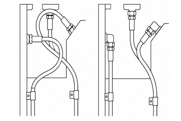
The hose needs a workable route after point T. Compare the proposed tangent direction with the hose manufacturer’s minimum bend radius, any required straight section near the fitting, torsion limits, clamps, abrasion protection, and movement allowance. Do not force an early bend to clear an obstacle.

A shorter elbow may reduce metal projection while crowding the hose against the port block. A longer elbow may improve the first bend but interfere with another component. The decision must include both rigid fitting geometry and flexible hose behavior.

Separate Installation Clearance From Operating Clearance

Installation clearance answers whether the fitting can be placed, oriented, tightened, and removed. Operating clearance answers whether the complete assembly remains clear under pressure response, vibration, temperature, and equipment motion.

Check assembly and service access

Model the path needed to insert the fitting, rotate a threaded or swivel element as designed, place seals or clamps, engage tools, and apply the approved installation procedure. Include future inspection and removal. A cover that can be removed may solve one step, but document that required sequence and confirm it is practical and safe.

For two nearby elbows, check whether one must be installed before the other and whether that sequence still permits correct orientation and tightening. Do not leave a connection partly loose merely to preserve access.

Check movement through the operating range

Identify moving cylinders, linkages, booms, guards, suspension components, articulated joints, and hose bundles. Compare the assembly envelope at every relevant equipment position using an approved safe method. Account for hose movement, growth, vibration, and support requirements from current design data.

A visible static gap is not automatically sufficient operating clearance. Do not invent a universal gap or tolerance; define required separation through the equipment design, component instructions, motion analysis, and risk assessment.

Verify Orientation and Rotation Without Guessing

Elbow direction is a three-dimensional requirement. “Pointing up” or “same as the old one” is unreliable unless the drawing defines the viewing direction and angular datum.

Specify clocking from a controlled view

Choose a datum feature on the port, flange, fitting connection, or equipment and state the direction from which orientation is viewed. Define the hose centerline angle relative to that datum. For a two-ended hose assembly, include the relative angular orientation of both ends and the finished-length reference.

If a female swivel nut permits installation rotation, distinguish nut movement from rotation of the complete elbow in service. If the elbow orientation locks as the connection is tightened, confirm that the approved installation method reaches both sealing condition and required direction.

Test the proposed outline before assembly

Overlay controlled fitting geometry on the equipment drawing or use an approved physical template, CAD envelope, or representative nonfunctional model. Include E1, E2, T, W, the hose bend corridor, and neighboring items. A screenshot without scale or datums is not a fit check.

Do not use a finished hydraulic assembly as the first template when interference could require force or damage. Resolve unclear geometry before crimping when possible, because changing the elbow later can also change hose cut length and end orientation.

Request Drawings and Measurements That Can Be Compared

Both original and proposed fittings should be described from the same functional references. Mixing catalog dimensions based on different datums can create a false mismatch or false approval.

Assembly routing

Fitting and interface package

Request the complete product drawing and revision, connection standard, male or female configuration, thread and seal details, fitting angle, port datum, L1 and L2 equivalents, E1 and E2 equivalents, body and ferrule outline, hose tangent T, orientation features, and tool-access information. Add the exact fitting series, hose side, stem, and retained ferrule.

For an old part, take orthogonal photographs and measurements from labeled datums, but identify wear or damage that may affect the result. A photo alone cannot establish hidden geometry, thread pitch, seat angle, or dimensional scale.

Equipment and hose-route package

Provide the port drawing, neighboring-port locations, surrounding obstacles, removable covers, installation sequence, tool envelope, motion range, hose supports, first clamp, required bend data, finished assembly length definition, and relative end orientation. Mark the contact point that triggered the review.

Also provide hose manufacturer, series, construction, size, and current fitting and crimp compatibility information. A dimensional pass does not approve the hose-and-fitting combination or the port sealing interface.

Apply Pass, Clarify, or Reject Decision Points

Use a decision record rather than a verbal “should fit” judgment.

DecisionEvidence conditionAction
PassConnection, symbolic dimensions replaced by controlled values, orientation, tool path, hose route, and motion envelope all satisfy requirementsRelease the exact configuration and drawing revision
ClarifyNo confirmed conflict, but a datum, dimension, movement condition, tool path, or source revision is missingHold and request the named evidence
RejectVerified interference, forced hose routing, unavailable tool access, wrong interface, or operation outside documented limitsSelect a different geometry or redesign through approved authority

Do not convert “clarify” to “pass” because the order is urgent. Document who reviewed the fit, which drawings were compared, assumptions that were resolved, and which product and equipment revisions the decision covers.

Before requesting a clearance review, prepare:

Retain the approved envelope with the assembly record so later replacements can be checked against the same geometry. The record should identify whether the review covered only installation, the full motion range, or both. If a cover, adjacent valve, clamp, hose bundle, or tool changes, repeat the affected portion of the fit check rather than assuming the original pass still applies. The same is true when a replacement fitting keeps the connection code but changes body shape, swivel length, ferrule, or elbow centerline. A controlled outline and decision history reduce repeat measurement while preventing an old approval from being applied to a physically different configuration.

Conclusion

Elbow clearance is a three-dimensional compatibility check, not a thread-and-angle comparison. Define a functional port datum, centerlines, drop, sweep, body and ferrule envelope, hose tangent, and tool space with symbolic dimensions, then replace those symbols with controlled drawing values. Compare the rigid fitting and flexible hose route with adjacent ports, covers, installation sequence, service access, and every relevant equipment position. Specify orientation from a named view and do not rely on a swivel nut, forced bend, or loose connection to correct interference. Use pass, clarify, or reject outcomes that preserve the reviewed revisions. For installation clearance on one-piece elbow fittings, prepare the dimensioned fitting outline, equipment envelope, hose-routing data, photographs, and unresolved fields before crimping or ordering.

Frequently Asked Questions

Does the correct port thread mean an elbow will fit?

No, thread and seal compatibility do not prove body, ferrule, hose, tool, or motion clearance. Review the complete three-dimensional envelope and orientation.

Is elbow drop the same as overall fitting length?

No, drop usually locates a centerline from a defined datum, while overall length can include several features. Use the exact drawing definitions for both products.

Can the hose be bent more sharply to clear a cover?

No, do not force routing below the hose manufacturer’s requirements or add twist near the fitting. Select suitable geometry or redesign the route through an approved process.

Should clearance be checked only with the equipment parked?

No, static installation and service access are only part of the review. Check relevant operating positions and hose movement through an approved safe method.

Can photographs replace an equipment drawing?

No, photographs help document obstacles and orientation but can distort scale and hide depth. Add labeled datums, dimensions, motion information, and controlled fitting and equipment drawings.

How to Specify Flange-End One-Piece Hose Fittings

How to Specify Flange-End One-Piece Hose Fittings

An RFQ that says only “flange fitting, same size as sample” is not enough to identify a safe replacement. Flange-end one-piece hose fittings must be specified through two linked definitions: the port-side flange interface and the hose-side assembly system. Nominal size alone cannot establish the flange family, head geometry, sealing feature, clamp compatibility, stem and ferrule design, or crimp requirements. Angle, orientation, overall envelope, and tool access also affect whether the fitting can be installed. A reliable request therefore uses controlled drawings, named datums, photographs, and complete hose information instead of assuming that visually similar flange heads are interchangeable.

Split the Specification Into Port Side and Hose Side

The most useful starting point is a two-part product definition. One part describes how the fitting mates and seals at the equipment; the other describes how it joins the hose through an approved assembly process.

1 inch crimp flange

Define the port-side question

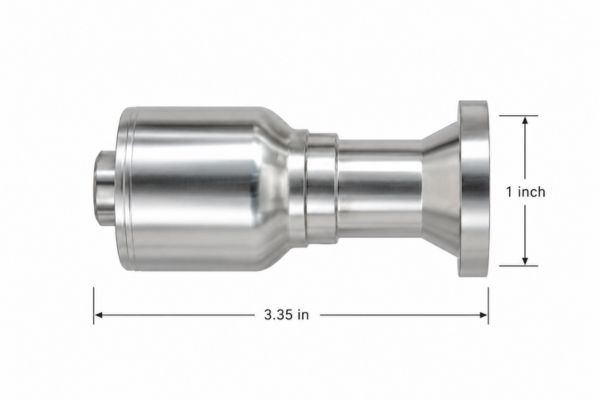
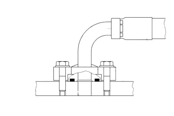
Record the flange interface required by the mating port or adapter, including the applicable standard or controlled equipment drawing. Identify nominal size only as one field. Add flange head dimensions, sealing arrangement, split or captive clamp context where relevant, fastener interface, and the functional connection datum used by the drawing.

Do not call a flange Code 61, Code 62, or another family from appearance or nominal size alone. Similar-looking heads can have different dimensions, pressure scopes, seals, clamps, or fastening requirements. The order should cite the source that establishes the interface rather than ask the supplier to infer it from a photograph.

Define the hose-side question

Record the complete hose manufacturer, hose series, construction, ID or dash size, and the fitting series approved for that hose. Identify whether the fitting body or stem and ferrule are preassembled or retained as a one-piece product and note the exact SKU or drawing revision when known.

The hose side also needs current preparation, insertion, crimp equipment, tooling, measurement, and acceptance data. Matching hose dash to flange nominal size does not prove compatibility. Port size and hose size serve different functions and may not be the same.

Keep these field groups separate in the RFQ:

Identify the Flange Interface From Controlled Evidence

Flange identification should begin with the mating equipment and its drawing whenever possible. An old fitting can supply useful dimensions, but wear, damage, and incomplete measurement can make it an unreliable sole standard.

Name the applicable interface source

Use the current equipment drawing, port drawing, applicable standard, or approved component specification that defines the connection. Record the document identifier and revision. If the interface is proprietary or modified, say so explicitly and request a controlled detail rather than forcing it into a familiar flange label.

Confirm whether the connection uses a flanged head with separate clamps, a block or pad, a captive arrangement, or another design. The word “flange” is not a complete product category. The specification must describe the exact mating system and the parts included or excluded from the order.

Keep identity separate from pressure suitability

Correct flange identification does not establish a universal working pressure. Suitability depends on the exact flange head, clamps, fasteners, seal, mating port, hose assembly, temperature, fluid, loading, installation, and applicable documentation. The lowest-rated or least-suitable component and condition can govern the assembly.

Do not copy a pressure value or torque from a visually similar connection. Request the current approved rating and installation procedure for the complete interface and application. If that evidence is absent, the specification remains incomplete.

Capture Head Geometry, Critical Dimensions, and Seal Type

The drawing should define dimensions from functional datums so both buyer and reviewer measure the same geometry. Avoid vague fields such as “head width” without a reference view.

Build a dimensioned interface view

Depending on the design, useful fields may include flange head width and thickness, sealing-face diameter, nose or pilot geometry, relevant radii, centerline location, and clearance around the clamp area. Name each datum and indicate whether the value comes from the equipment drawing, original fitting drawing, or controlled measurement.

Photographs should show the complete fitting, flange face, side profile, hose end, and a scale, but photos do not replace dimensions. A perspective image can distort thickness, diameter, and angle. Include a sketch with labeled dimensions even when a formal CAD drawing is not available.

Hydraulic flange adapters design

Identify how the interface seals

State whether sealing occurs through an O-ring, another specified seal, or a drawing-defined face arrangement. Record groove or seal location through controlled geometry and identify the required seal material only from approved fluid, temperature, and equipment data. Do not substitute a seal because it fits physically.

Inspect the mating face and old component for damage, but do not treat an imprint or leftover seal as conclusive evidence of the original design. If the seal type or groove geometry is unclear, request the port drawing and fitting detail before selection.

Confirm Clamp, Port, and Fastening Compatibility

The flange head works as part of an interface that may include clamps, bolts, washers, a mating pad, and an O-ring. Those surrounding parts need compatible geometry and approved installation requirements.

Describe the mating hardware context

Record the clamp style and part identity where known, the port or pad reference, fastener arrangement, and whether existing hardware is intended for reuse under the equipment procedure. Note obstacles that restrict clamp placement or bolt access. Do not assume every clamp matching the nominal flange size fits every head family.

The request should state whether clamps, seals, and fasteners are included with the fitting or supplied separately. This prevents a correct flange head from arriving without the components needed for the approved interface.

Leave torque and installation values to controlled data

Fastener grade, lubrication condition, thread condition, clamp design, port material, and manufacturer procedure can affect assembly requirements. Do not place a guessed torque in the RFQ or copy one from another flange. Cite the applicable installation instruction and revision instead.

Before disassembly or measurement, stop the equipment, isolate the hydraulic system, release pressure and stored energy, secure raised loads, and follow lockout and manufacturer procedures. Never loosen a flange connection to identify it while the circuit can contain pressure.

Complete the Hose-End and One-Piece Fitting Definition

A correct flange head attached to the wrong stem or ferrule still creates an unacceptable hose assembly. The specification must connect the port geometry to an approved hose-side system.

State size, series, and assembly basis

List hose manufacturer, complete series, construction, ID or dash, fitting series, and full fitting code when available. Add the required preparation method, such as skive or no-skive only when current approved data specify it, along with insertion reference, machine basis, tooling, crimp measurement method, and acceptance-document revision.

Do not publish or infer a universal crimp diameter, insertion depth, die, or preparation rule. Each value must apply to the exact hose, fitting, ferrule, equipment, and controlled procedure. If mixed-brand use is proposed, request explicit approval evidence for that combination.

Define angle and orientation

Identify straight, 45-degree, 90-degree, or other drawing-defined geometry. For angled ends, specify the relationship between the flange sealing face, clamp orientation, elbow plane, and hose centerline. For a two-ended hose assembly, include relative end clocking and the method used to measure it.

Terms such as “left,” “up,” or “same as old” are ambiguous without an installed reference. Use a labeled view, datum, and viewing direction. Swivel capability during installation does not automatically permit rotation during service.

Verify Envelope, Routing, and Service Clearance

An interface can be technically correct and still fail to fit the equipment. Compare the proposed fitting’s complete three-dimensional envelope with adjacent ports, guards, structures, hoses, and the tools needed for installation.

Map the rigid fitting envelope

Use drawing dimensions to locate the flange face, elbow centerline, body, ferrule, and hose tangent relative to the equipment port. Check head and clamp clearance, body projection, elbow drop or sweep, and the space required to insert and tighten hardware. A nominal angle does not define those distances.

For replacement work, compare the old and proposed outlines from the same datum. Do not force the hose, bend it below manufacturer limits, or use clamp tightening to pull a misaligned fitting into position.

DIN vs ANSI Hydraulic Flanges Applications

Include operating and maintenance space

Installation clearance is only the static starting point. Review hose bend radius, movement, vibration, articulation, nearby hot or abrasive surfaces, and equipment motion using approved design data. Preserve access for inspection, retightening when specified, and future removal without using the hose as a handle.

If a full motion check is needed, use a safe approved method with pressure released and loads controlled. A gap observed in one machine position does not prove clearance throughout operation.

Write a Specification Line That Exposes Unknowns

A structured line reduces assumptions by making missing fields visible. Use placeholders until each field is supported; do not fill them with guessed codes or dimensions.

Example specification format

Flange-end one-piece hose fitting: Interface standard/drawing [document and revision]; nominal interface size [value]; head geometry [drawing/dimensions]; seal type and location [approved definition]; clamp/port context [part or drawing]; hose manufacturer and series [identity]; hose size [identity]; fitting series/SKU [identity]; configuration [straight/angle]; orientation datum [drawing reference]; material/finish [requirement]; envelope limits [dimensioned sketch]; assembly/crimp instruction [document and revision]; application conditions [fluid, pressure, temperature, motion, environment].

This format is a request framework, not a technical approval. Every bracketed field should trace to an equipment requirement, product drawing, compatibility record, or approved process source.

Drawing and photo request checklist

Prepare the following package before ordering:

When a field cannot be confirmed, keep the placeholder visible and assign it to a source owner. For example, the equipment drawing owner may need to confirm the port interface, while the hose-system authority confirms the fitting series and crimp basis. Do not let a commercial description silently become an engineering decision. The response to the RFQ should repeat the proposed values, drawing revisions, inclusions, exclusions, and remaining exceptions so they can be reviewed line by line. If a proposed product differs from the requested envelope, seal arrangement, hose combination, or hardware context, require a revised drawing and technical disposition before approving the order. This closed-loop comparison prevents an incomplete request from becoming an equally incomplete purchase record.

Conclusion

A usable flange fitting specification connects a verified equipment interface to a verified hose assembly system. Identify the applicable flange standard or controlled drawing, define head geometry and sealing details from named datums, and document the clamp, port, fastener, and included-part context. Then add the exact hose series, size, fitting and ferrule design, approved crimp process, angle, orientation, and application conditions. Compare the complete envelope with routing, motion, and service access before approving a replacement. Nominal size, a photo, or a familiar flange label cannot prove interchangeability or pressure suitability. For flange-end one-piece hose fittings, the next practical step is to prepare a revision-controlled port drawing, dimensioned fitting sketch, hose data, assembly instruction, and list of unresolved fields.

Frequently Asked Questions

Is nominal flange size enough to select a hose fitting?

No, nominal size does not define the flange family, head geometry, seal, clamps, hose side, or pressure scope. Confirm the complete mating interface from a current standard or controlled drawing.

Can an old flange fitting be identified from photographs alone?

No, photographs support screening but can distort or hide critical geometry. Add controlled dimensions, functional datums, sealing details, part markings, and the mating-port drawing.

Should clamps and seals be included in the fitting specification?

Yes, the request should state clearly whether they are included or supplied separately. Their exact identity and compatibility still require approved interface data.

Does the flange size have to match the hose dash size?

No, port-interface size and hose size describe different parts of the assembly. Select each from the application and approved product data rather than assuming the labels must match.

Can torque be copied from a similar flange connection?

No, installation requirements depend on the exact interface, hardware, condition, and manufacturer procedure. Cite the current controlled installation instruction instead of using a borrowed value.

How Do Inspection and Testing Support Hose Assembly Quality

How Do Inspection and Testing Support Hose Assembly Quality?

“The fitting passed inspection” and “the hose assembly passed testing” sound similar, but they certify different evidence. In fitting inspection vs hose assembly testing, component checks can confirm defined drawing, thread, material, finish, or dimensional requirements, while finished-assembly tests assess a specific hose-and-fitting configuration under a named method and controlled conditions. Neither statement guarantees zero failure, and neither can replace verified compatibility, process control, or application review.

Start with the Two Different Claims

The useful distinction is the object being evaluated. Fitting inspection examines the component; hose assembly testing examines an assembled configuration produced by a defined process.

Component acceptance claim

A component acceptance statement should identify the exact fitting code, drawing revision, lot, inspected characteristics, method, results, and acceptance criteria. It may show that threads, sealing geometry, dimensions, material documentation, finish, markings, or other specified features meet their controlled requirements.

It cannot show by itself that the fitting matches a particular hose construction, that the assembly was inserted and crimped correctly, or that the finished combination performs under a specific pressure, temperature, impulse, routing, or environmental condition.

test crimp Fitting Thread

Finished-assembly test claim

An assembly test statement should identify the hose, both fitting ends, preparation, crimp process, machine, tooling, sample traceability, test method, conditions, measured results, and acceptance basis. It may show how that exact configuration behaved during the named test.

It cannot automatically approve every size, hose series, fitting end, material, process, or application. A passed sample is evidence within its documented scope, not proof that every related assembly will be defect-free.

What Fitting Component Inspection Can Verify

Component inspection compares defined characteristics with controlled product requirements. Its strength is precise identity and conformance evidence before the fitting becomes part of an assembly.

Dimensions, threads, and sealing features

Inspection can evaluate the dimensions identified on a drawing using suitable calibrated instruments or gauges. Depending on the specification, this may include thread form, diameter, pitch or TPI, straight or tapered condition, seat angle, sealing face, O-ring groove, stem or ferrule features, orientation, and overall geometry.

The inspection record must state what was measured and which revision supplied the criteria. A thread gauge result cannot establish the sealing method, and a matching thread cannot prove that two connections have the same seat, sealing face, or port interface. Visual similarity is not a substitute for complete identification.

Material, finish, and marking evidence

Incoming or production records may compare material certificates, finish documentation, hardness or coating checks when specified, and product markings with controlled requirements. These records can support identity and lot acceptance when their sources and traceability are valid.

They cannot turn a material or finish into a universal choice. Suitability still depends on fluid, corrosion, temperature, mechanical load, regulations, and equipment requirements. A salt-spray result or certificate does not directly predict actual service life in every field environment.

What Component Inspection Cannot Establish

Even complete fitting inspection stops at the component boundary. It does not recreate the interaction among hose, fitting, crimping process, and application.

Hose-side compatibility

A fitting may meet every drawing dimension and still be incompatible with an unapproved hose. Hose tube, reinforcement, cover, ID, OD, and construction interact with stem and ferrule geometry. The same nominal dash size does not establish the required engagement or compression.

Compatibility must come from current manufacturer data or another approved technical basis for the exact hose manufacturer, hose series, size, and fitting code. Do not infer it from a successful thread inspection, brand cross-reference, or component part number alone.

Assembly workmanship and process output

Component inspection cannot show whether the hose was cut and prepared correctly, reached the specified insertion position, remained aligned, used the correct crimper and die set, or met the approved finished crimp criteria. Those conditions arise during assembly and require process records and finished-piece inspection.

Nor can a fitting inspection prove retention, leakage resistance, pressure behavior, impulse durability, or application suitability of the finished assembly. Those claims require evidence designed for the assembly and decision in question.

What Finished Hose Assembly Testing Can Assess

Assembly tests evaluate the combined behavior of identified components and a documented process under controlled conditions. Their value depends on a test method that matches the claim.

Method-specific performance

A leakage test can assess leakage under its defined fluid, pressure, temperature, duration, and observation method. A proof-type test can assess the sample against its specified proof criteria. An impulse test can examine repeated pressure-cycle behavior under its controlled configuration. Other methods may examine pull-off, burst, environmental effects, or another specified characteristic.

These examples explain evidence categories, not universal procedures. Use the applicable standard, customer specification, manufacturer plan, or approved internal method for actual conditions and limits. Never invent pressures, cycle counts, temperatures, or acceptance values.

pressure inspection

Interaction of the complete configuration

When traceability is complete, a test can capture interaction among the named hose, fitting, preparation, crimp process, and test conditions. A failure location or mode may provide evidence for investigation, while a passed result supports the defined acceptance claim.

Testing does not replace the need to inspect component identity and dimensions. A test sample assembled from the wrong lot or undocumented design may produce a result that cannot be applied to the intended product.

What Assembly Testing Cannot Guarantee

Testing has boundaries set by sample selection, configuration, method, and conditions. Strong review makes those boundaries explicit.

No universal transfer across variants

Evidence for one hose size, fitting code, end configuration, material, crimp machine, or process revision should not be transferred automatically to another. A technical validation plan may define a family or worst-case rationale, but that scope must be documented and approved; reviewers should not invent it after the test.

A passed assembly does not authorize interchangeability with Parker or another brand. Cross-references may identify candidates for comparison, but drawings, hose compatibility, crimp data, and relevant validation must support the actual replacement.

No guarantee of zero field failure

Controlled testing cannot reproduce every production variation, installation error, routing condition, pressure transient, temperature change, fluid, abrasion exposure, contamination event, or maintenance history. Field suitability requires application review and ongoing process control in addition to validation evidence.

Pressure suitability is limited by the lowest-rated component in the complete system or assembly and may be affected by impulse, temperature, bend radius, vibration, installation, damage, and age. One laboratory result cannot remove those conditions.

Map Claims to the Correct Evidence

Hose assembly quality review should ask which record directly supports each claim. Substituting a neighboring evidence type creates false confidence.

Claims–evidence comparison

“Can show” means the evidence is capable of supporting the claim when it is complete and valid. It does not mean that any document with that title is sufficient.

Ask boundary questions

For every record, ask:

These questions expose whether a claim is supported, incomplete, or outside the evidence scope.

Keep Design Verification, Routine Inspection, and Application Review Separate

Three approval layers answer different questions. Combining them into one “quality passed” label makes later decisions difficult to audit.

Design and process verification

Design verification asks whether the fitting and intended assembly design meet defined requirements. It may use drawing review, analysis, prototypes, compatibility studies, and applicable tests. Process verification or validation asks whether the controlled assembly process can produce the intended result with defined equipment, tooling, instructions, and operators.

Changes to the hose, stem, ferrule, material, finish, tooling, software, crimp data, or test method may require review of existing evidence. Version control is part of technical validity.

Thread inspection

Routine acceptance and application suitability

Routine inspection checks production or incoming lots against specified characteristics and sampling plans. It does not repeat the entire design validation on every part. Application review then compares the approved product and assembly with the actual pressure, temperature, fluid, routing, vibration, corrosion, installation, and equipment requirements.

No layer should be asked to do the work of another. Routine dimensional acceptance cannot waive application conditions, while a design test cannot excuse mixed parts or poor crimp execution in production.

Apply a Layered Approval Framework

A release decision is strongest when evidence is assembled in order and every layer retains its boundary. Missing evidence should create a hold, not an assumption.

Layer 1: component and configuration

Confirm fitting identity, drawing, dimensions, threads, sealing features, material, finish, and lot evidence. Confirm hose manufacturer, series, size, construction, and lot. Verify that controlled compatibility records join the exact pair.

Assembly and performance evidence.

Confirm cutting and preparation, insertion, crimper, tooling, program, instruction revision, first-piece results, and routine controls. Then review applicable finished-assembly tests for exact configuration, method, conditions, samples, results, deviations, and approval scope.

Layer 3: application and change control

Compare the approved assembly with operating and environmental requirements. Record the decision and the evidence versions used. When a component, process, document, or application changes, determine which layers require renewed review before release.

This framework avoids two common errors: calling a conforming fitting a validated assembly, and calling a passed test a guarantee for every production and field condition.

Record unresolved gaps beside the layer they affect. A missing material record should not be disguised by a successful assembly test, and a missing compatibility approval should not be disguised by precise component measurements. Keep release on hold until the evidence owner resolves the relevant boundary.

Conclusion

Component inspection and assembly testing are complementary evidence, not substitutes. Fitting inspection can show whether identified parts meet controlled drawing, thread, material, finish, and dimensional requirements, but it cannot prove hose compatibility or assembly performance. Finished testing can show how a traceable hose-and-fitting configuration behaved under a named method and conditions, but it cannot approve every variant or guarantee zero failure. Combine component records with compatibility data, crimp-process evidence, method-specific test reports, and application review. Keep design verification, routine acceptance, and field suitability distinct, and reassess evidence after relevant changes. That layered approach makes fitting inspection vs hose assembly testing a clear approval framework instead of two misleading pass statements.

Frequently Asked Questions

Can a thread gauge prove that a fitting will seal correctly?

No, a thread gauge evaluates specified thread characteristics, not the complete sealing interface. Seat, sealing face, O-ring location, surface condition, and mating-port requirements must also match.

Does a pressure test replace dimensional inspection?

No, a test result for a sample does not confirm that every fitting or assembly dimension meets its drawing. Dimensional controls and method-specific testing address different evidence.

Can one passing assembly qualify an entire product family?

Only when an approved validation plan defines and justifies that scope. Do not extend one sample to other sizes, ends, materials, hose series, or processes without documented authority.

Is incoming fitting inspection enough before crimping?

No, the shop must also verify hose compatibility, preparation, insertion, machine, tooling, crimp data, and finished-piece acceptance. Component conformance is only one layer.

Which record should a buyer request first?

Start with exact product and configuration identity, then request the evidence relevant to the claim: component inspection, compatibility and crimp records, or a traceable test report. A generic certificate is not a replacement for scoped evidence.

How to Identify JIS One-Piece Hose Fittings Correctly

How to Identify JIS One-Piece Hose Fittings Correctly

A look-alike connection can thread into a mating part and still be the wrong JIS interface, seat, or sealing system. To identify JIS one-piece hose fittings correctly, separate the complete fitting series from the connection end, then verify thread form, diameter, pitch, male or female configuration, seat or cone geometry, sealing method, and hose-side design against current controlled references. Do not treat “JIS” as one universal thread-and-seat combination. Metric, BSP-related, and flare-style connections can appear similar in a photograph, while the stem and ferrule may require different hose and crimp data even when the port end is identified.

Treat the Look-Alike Failure as an Identification Problem

When a suspected replacement starts into a port but does not seat correctly, the problem is not solved by applying more torque or sealant. Engagement proves only that some thread features are close enough to begin mating; it does not prove the standard, pitch, seat, seal, or functional dimensions.

1FU43 crimp hydraulic fittings

Stop before force damages the evidence

Do not force-mate a suspected JIS connection. Cross-threading, mismatched seats, damaged sealing faces, and distorted swivel components can destroy the features needed for identification and create an unsafe assembly. Stop the equipment, isolate hydraulic pressure, release stored energy, secure raised loads, and follow lockout and equipment instructions before removing an installed fitting.

Keep the original fitting, mating component, caps, labels, and part records together. Clean only through an approved method that will not alter threads, seats, finishes, markings, or seals. Photograph the condition before further handling when damage or contamination could affect the conclusion.

Record why the first identification failed

Note whether the original decision came from a photo, a partial part number, an assumed country standard, thread engagement, nominal size, or comparison with a nearby fitting. That record helps prevent the same shortcut from being repeated. “Looks JIS” is not a measurable product definition.

Describe the actual mismatch: stops after partial engagement, nut bottoms without face contact, visible seat gap, different pitch indication, wrong swivel form, or incompatible hose end. Do not convert the symptom into a standard name until measurements and references support it.

Separate Series Identity From Connection Identity

A complete one-piece fitting contains more than its port connection. The series and hose-side construction determine which hose and crimp process may be approved, while the connection identity determines how the other end mates and seals.

Identify the complete fitting record

Search for a full product code, manufacturer marking, label, drawing, equipment parts list, or purchase record. Record straight, 45-degree, or 90-degree form; male or female end; swivel or fixed construction; material or finish requirement; hose size; fitting series; stem; and retained ferrule details.

A one-piece fitting normally has the body or stem and ferrule preassembled, attached, or retained together, but exact construction varies by series. That structure may reduce separate ferrule selection; it does not make every JIS-style port end compatible with every hose or crimp system.

Identify the connection as a separate layer

Create a connection record that names thread form, measured diameter, pitch, straight or tapered condition, seat or cone feature, sealing face, O-ring or other seal location, and mating-part requirements. Keep observations separate from conclusions. For example, write “measured pitch indication” and “visible internal cone” before assigning a catalog description.

This separation prevents a correct port-end identification from being used to approve the hose side. It also prevents a known fitting series from becoming a shortcut for guessing the exact connection variant.

Preserve an identification evidence pack containing:

Establish the Applicable JIS Reference

JIS identification requires the current standard, manufacturer catalog, or controlled drawing that actually covers the candidate connection. Do not rely on a generic chart that groups several Japanese hydraulic interfaces under one label.

Verify document scope and revision

Check the title, issuer, revision, effective status, and product scope of the reference. Confirm that it defines the same male or female interface, thread form, seat or flare arrangement, and size family being inspected. A valid JIS document for one connection type does not define every fitting commonly described as JIS.

Manufacturer drawings may add product-specific body, swivel, stem, ferrule, or dimensional details beyond the connection standard. Use the connection reference to identify the mating interface and the product drawing to identify the complete one-piece fitting. If the two conflict, place the candidate on hold and request clarification from the document owner.

Avoid unsupported standard cross-references

Do not say that a JIS connection is equivalent to a BSP, metric, DIN, SAE, or another interface merely because a secondary chart places them near each other. Equivalent-looking nominal descriptions may still differ in thread series, tolerance, seat geometry, sealing method, or application scope.

Record any cross-reference as a search lead until dimensions and functional features have been checked against primary or controlled technical data. Never promise interchangeability without evidence that covers the exact mating pair and application.

Measure Thread Form, Diameter, and Pitch

Thread measurement narrows the candidate list, but it must be performed on clean, undamaged features with suitable tools. No single measurement establishes the complete connection.

1FU43 crimp hydraulic fitting Drawing Topa

Build a repeatable thread record

First identify male or female form and determine whether the thread appears straight or tapered through the approved method. Measure the appropriate outside or inside diameter at the defined location. Use a suitable pitch gauge or other controlled method to identify pitch or threads per inch, and record the observed value without rounding it to the nearest familiar catalog entry.

Check several usable thread locations when damage, plating, dirt, or limited engagement affects the reading. For a tapered thread, diameter changes with position, so the datum matters. Do not measure across burrs or infer taper from one visual angle.

Compare a combination, not one field

Use thread form, measured diameter, pitch, sex, and straight or tapered condition together to filter the current reference. A pitch match with a different diameter is not acceptable; neither is a diameter match with a different pitch. Thread engagement should never be used as a substitute gauge.

The thread record should state:

If readings fall between candidates or instruments cannot reach the feature correctly, classify the result as unresolved. A worn thread, damaged lead, or short thread length may require a drawing, specialized gauge, or qualified inspection rather than repeated trial mating.

Inspect the Seat, Cone, and Sealing Interface

The sealing interface is often the decisive difference between connections with similar threads. JIS-related fitting families do not all use one universal seat angle or sealing method, so the interface must be verified from the applicable reference.

Identify where sealing is designed to occur

Look for a male or female cone, flare seat, flat face, O-ring location, bonded-seal surface, tapered-thread seal, or another drawing-defined interface. Record the location and orientation of the feature. Inspect for damage that could disguise the original profile, including dents, galling, scratches, corrosion, or a deformed cone.

Use a suitable seat gauge, profile method, or controlled drawing comparison when required. Do not estimate an angle from a photograph or place an unverified gauge against a delicate sealing face. A thread that fits cannot compensate for a different seat angle or sealing location.

Examine the mating component too

The port, adapter, tube end, or hose fitting that mates with the candidate provides essential evidence. Confirm its thread, seat, seal, and intended interface from a drawing or known part identity. An old fitting may have wear marks that show contact, but marks alone do not prove the original standard.

Do not use thread sealant to overcome an incorrect seat, damaged face, straight-versus-tapered mismatch, or wrong thread family. Sealant cannot redesign where the connection is meant to contain pressure.

Record Female, Male, Swivel, and Hose-Side Details

Complete identity includes functional construction around the connection. A female swivel nut that turns for assembly is not automatically a live swivel intended for continuous movement, and a familiar nut shape does not establish its thread or seat.

Characterize the port-end construction

Record fixed or swivel form, nut or body wrenching features, retention, accessible thread condition, seat position, and the orientation of an elbow relative to the connection. Check the current drawing for expected axial behavior or movement; do not force, lubricate, or disassemble the swivel to make it resemble a reference sample.

For angled fittings, capture the centerline, drop, and envelope dimensions from named datums. Installation clearance can distinguish candidates that otherwise share connection labels, and it affects whether the hose can meet its bend requirements without interference.

Complete the hose-side identity

Record hose manufacturer, hose series, construction, ID or dash, fitting series, ferrule design, stem features, and the current compatibility record. Verify the approved preparation, insertion, crimp equipment, die set, measurement method, and acceptance data for the exact combination.

Do not assume that a JIS port end determines the hose side. The same connection type may be offered across multiple fitting systems, and matching dash numbers do not prove hose compatibility.

Follow a Gauge-and-Dimension Verification Sequence

A fixed sequence reduces confirmation bias. Begin with observations that do not require mating or alteration, then compare the resulting feature set with controlled references.

Photographs can document markings, general shape, damage, and orientation. They usually cannot prove pitch, taper, seat angle, sealing contact, hidden stem geometry, or exact scale. Include front, side, seat, thread, hose-side, and installed views with a scale and labeled measurement references, but do not make the final order from images alone.

The order record should repeat the accepted connection reference, complete fitting code, drawing revision, hose combination, configuration, material or finish requirement, and any unresolved exception. Have the reviewer compare that record with the proposed supplier drawing rather than accepting a shortened commercial description. If the proposed drawing changes the thread, seat, seal, hose stem, ferrule, angle, or envelope, return the decision to clarification. This final comparison keeps a careful identification from being lost when the information moves from inspection to purchasing.

Conclusion

Reliable JIS fitting identification comes from matching a complete feature set, not recognizing a familiar shape. Preserve the original evidence, separate fitting-series identity from connection identity, and use a current reference that covers the exact interface. Measure thread form, diameter, pitch, sex, and taper; then verify the seat, cone, seal location, mating component, swivel construction, angle, and critical dimensions. Complete the decision with hose manufacturer, series, size, stem, ferrule, and approved crimp data. When sources conflict or a feature cannot be measured reliably, hold the candidate rather than force-mating it or claiming interchangeability. That forensic sequence is the defensible way to identify JIS one-piece hose fittings before ordering or assembly.

Frequently Asked Questions

Does a BSP-looking thread prove the fitting is not JIS?

No, visual resemblance does not establish the governing connection standard. Measure the thread and sealing features, then compare the complete interface with current controlled references.

Do all JIS hose fittings use the same seat angle?

No, JIS-related fitting families should not be reduced to one universal seat. Identify the exact series and verify its seat or sealing interface from the applicable standard or drawing.

Can thread engagement confirm a JIS connection?

No, similar threads may begin to engage while having a different pitch, tolerance, taper, or sealing interface. Never force the mating parts as an identification test.

Is a part number enough to order the replacement?

Only when the number is complete, current, and traceable to a controlled product definition. Confirm the connection, geometry, hose side, and revision before relying on it.

What information should accompany a JIS fitting inquiry?

Provide markings, existing part number, male or female form, thread measurements, seat and seal details, fitting angle, critical dimensions, photos, mating component, hose identity, and application information. Mark every unresolved field clearly.

Contact Topa

Save 30% on maintenance costs with our easy-install hydraulic fittings. Contact Now!