Hydraulic hose assemblies are the vital arteries of countless industrial systems, from massive construction equipment to precision manufacturing machinery. Despite their critical importance, the process of ordering these components remains fraught with potential pitfalls. The complex technical language, numerous parameters, and intricate specifications create a minefield of opportunities for costly mistakes. We’ll explore the detailed coding system used in ordering, the precise methods for measuring assembly length, the critical importance of assembly angles, the rules governing natural bending direction, and essential technical parameters that influence performance and longevity.
Hose Assembly Length Measurement Methods
Standard Measurement Methodology
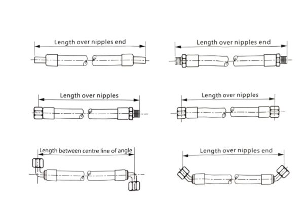
The accurate measurement of hose assembly length is a fundamental aspect of proper specification that directly impacts system performance and component longevity. According to industry standards, hose assembly length L is measured from the core end face of straight fittings or from the core center of bent fittings. This standardized approach ensures consistency across different manufacturers and applications.
For precise measurements, specific considerations apply to different fitting types:
- For straight fittings: Measurement is taken from the core end face, which is typically the plane where the fitting contacts the connected equipment
- For bent fittings: Measurement is taken from the core center, which is the central point of the bent section
Proper measurement requires appropriate tools:
- Steel measuring tape (with precision of at least 1mm)
- Calipers (for precise fitting dimension measurements)
- Specialized measurement fixtures (for specific hose assembly models)
The importance of accurate length measurement cannot be overstated. A hose that is too short will experience excessive tension during operation, significantly reducing its service life. Conversely, a hose that is too long may experience excessive bending or abrasion against nearby components, potentially leading to premature failure.
Common Measurement Pitfalls
Several common errors frequently occur during hose assembly length measurement:
- Incorrect reference points: Many technicians erroneously measure from the outer end of the fitting or from the connection point between the hose and fitting, rather than from the standard core end face or core center
- Failure to account for hose curvature: Hose assembly length should be measured in its natural state, not forcibly straightened
- Temperature effects ignored: Certain hose materials may experience slight length variations at different temperatures
- Tolerance requirements overlooked: Different hose assembly specifications have different length tolerance requirements
These measurement errors can lead to significant problems during installation and operation. For example, a hose assembly that is measured incorrectly and produced too short may be impossible to install without applying excessive force, creating built-in stress that will accelerate failure. Alternatively, an excessively long hose may create routing problems, interference with moving parts, or excessive slack that leads to abrasion damage.
Length Tolerances and Practical Applications
According to industry standards, hose assembly length tolerances typically follow these guidelines:
- Length ≤630mm: ±6mm
- Length 631-1250mm: ±12mm
- Length 1251-2500mm: ±20mm
- Length >2500mm: ±1.5%
These tolerance ranges reflect the practical realities of manufacturing processes and the functional requirements of hydraulic systems. When selecting appropriate length for specific applications, several factors must be considered:
- Installation space constraints
- Movement requirements for dynamic applications
- Thermal expansion and contraction
- Pressure-induced elongation or contraction
- Routing requirements to avoid interference with other components
In practical applications, it is often advisable to include a modest length margin (typically 5-10%) beyond the minimum required length to accommodate installation variations and to prevent excessive tension. However, this additional length must be balanced against the risk of excessive bending or interference issues.
Assembly Angle Representation Methods
Definition and Importance of Assembly Angles
The assembly angle is a critical parameter that defines the relative angular relationship between the two end fittings of a hose assembly. This specification directly impacts the hose’s installation path and stress distribution. Proper assembly angle specification provides several significant benefits:
- Reduces torsional stress in the hose, extending service life
- Ensures the hose follows the designed routing path, preventing interference and abrasion
- Simplifies the installation process, improving assembly efficiency
- Reduces system pressure loss, enhancing energy efficiency
In hydraulic systems where space constraints and component movement are significant factors, the precise specification of assembly angles becomes particularly crucial. Incorrect assembly angles can lead to hose twisting, excessive bending, or improper routing, all of which contribute to premature failure and system inefficiency.
Detailed Measurement Methodology
The standard method for measuring assembly angles follows these steps:
- Place the hose assembly along a straight line
- Position one of the fittings in a vertical orientation
- Measure the angle between the second fitting and the vertical direction in a clockwise direction
- This measured angle is the assembly angle
This standardized approach ensures consistency across different manufacturers and applications. The measurement requires appropriate tools:
- Protractor or angle gauge
- Specialized assembly angle measurement fixtures
- Digital angle measurement devices
For complex hose assemblies with multiple bends or special routing requirements, more sophisticated measurement techniques may be necessary, potentially involving 3D coordinate measurement or digital modeling.
Tolerance and Adjustment
According to industry standards, the allowable tolerance for assembly angles is typically ±3°. This tolerance range accounts for several factors:
- Assembly process variations
- Measurement tool precision limitations
- Elastic deformation of hose materials
When the actual assembly angle exceeds the tolerance range, several remedial actions may be necessary:
- Refitting the end connections
- Adjusting the hose cut length
- In extreme cases, replacing the entire hose assembly
The ±3° tolerance provides a practical balance between manufacturing feasibility and functional requirements. In most applications, this tolerance range is sufficient to ensure proper installation and performance. However, certain precision applications may require tighter tolerances, necessitating specialized manufacturing processes and quality control measures.
Assembly Angle Representation in Ordering Codes
Assembly angles are represented in ordering codes using “V” followed by the angle value. For example:
- V0: Indicates a 0-degree assembly angle (both fittings aligned in the same direction)
- V90: Indicates a 90-degree assembly angle (fittings perpendicular to each other)
- V180: Indicates a 180-degree assembly angle (fittings pointing in opposite directions)
- V270: Indicates a 270-degree assembly angle (fittings perpendicular, in the opposite direction from V90)
This standardized notation system allows for clear communication of assembly angle requirements between engineers, maintenance personnel, and manufacturers. The “V” prefix distinguishes assembly angle specifications from other numerical parameters in the ordering code.
Natural Bending Direction Regulations
Concept and Importance of Natural Bending Direction
The natural bending direction of a hose assembly refers to the inherent bending plane that the hose assumes when no external force is applied. Understanding and correctly applying natural bending direction is crucial for several reasons:
- Ensures the hose is installed without torsional stress
- Extends the service life of the hose
- Reduces system pressure loss
- Improves overall system reliability
When a hose is manufactured, particularly those with wire reinforcement, it develops a natural tendency to bend in a specific plane. Installing the hose contrary to this natural bending direction introduces torsional stress, which significantly reduces service life and can lead to premature failure. Industry studies have shown that hoses installed against their natural bending direction may experience up to a 70% reduction in service life compared to properly installed assemblies.
Detailed Analysis of Two Bent Fittings Configuration
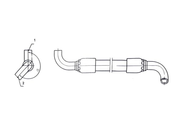
When both ends of a hose assembly have bent fittings, the measurement methodology is as follows:
- Straighten the hose assembly and observe it along a straight line
- Position bent fitting 1 in a vertical upward direction
- Measure the angle between bent fitting 2 and the vertically positioned bent fitting 1 in a clockwise direction
- This angle is the assembly angle, represented by V
For example, when the assembly angle is 225°, it is marked as V225.
This standardized approach ensures consistency in specifying the relationship between the two bent fittings. The measurement requires careful attention to the orientation of both fittings relative to each other and to the natural bending plane of the hose.
One Bent Fitting and One Straight Fitting Configuration
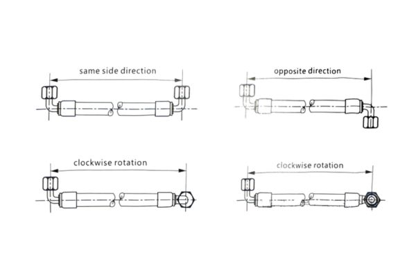
When a hose assembly has one bent fitting and one straight fitting, four basic configurations exist:
- The bent fitting’s bending plane aligns with the hose’s natural bending plane, with the same bending direction
- The bent fitting’s bending plane aligns with the hose’s natural bending plane, with opposite bending directions
- The bent fitting’s bending plane is perpendicular to the hose’s natural bending plane, bending to the left
- The bent fitting’s bending plane is perpendicular to the hose’s natural bending plane, bending to the right
The determination method involves:
- Placing the hose naturally on a horizontal surface
- Observing the relationship between the bent fitting and the hose’s natural bending direction
- Identifying the specific configuration based on the four scenarios described above
This assessment requires experience and careful observation, as the natural bending plane may not always be immediately obvious, particularly in hoses with multiple reinforcement layers or special construction.
Complex Configurations with Two Bent Fittings
When both ends of a hose assembly have bent fittings, the situation becomes more complex.
- Two bent fittings with parallel bending planes, same bending direction, aligned with the hose’s natural bending plane
- Two bent fittings with parallel bending planes, opposite bending directions, aligned with the hose’s natural bending plane
- Two bent fittings with parallel bending planes, same bending direction, perpendicular to the hose’s natural bending plane
- Two bent fittings with parallel bending planes, opposite bending directions, perpendicular to the hose’s natural bending plane
- Two bent fittings with perpendicular bending planes, one aligned with the hose’s natural bending plane, the other perpendicular to it
- Two bent fittings with perpendicular bending planes, both at 45° angles to the hose’s natural bending plane
- Two bent fittings with bending planes at arbitrary angles, with complex relationships to the hose’s natural bending plane
These complex configurations require specialized measurement tools and methods for accurate assessment, typically performed by experienced technical personnel. The complexity of these configurations highlights the importance of proper documentation and communication when ordering replacement hose assemblies.
Hose Technical Parameter Selection Guide
Hose Inner Diameter Selection
The inner diameter is one of the most critical parameters, directly affecting system flow and pressure loss. Selection principles include:
Flow-Based Calculation:
Excessive flow velocity leads to high pressure loss and system heating
Recommended hydraulic oil flow velocity ranges:
- Suction lines: 0.5-1.5 m/s
- Return lines: 2-4 m/s
- Pressure lines (<7MPa): 3-5 m/s
- High-pressure lines (>7MPa): 4-6 m/s
Calculation Formula:d = √(4Q/πv) Where: d is inner diameter (m), Q is flow rate (m³/s), v is flow velocity (m/s)
Standardized Selection: After calculating the theoretical inner diameter, select the closest standard size. Common standard inner diameters include: 6mm, 8mm, 10mm, 12mm, 16mm, 19mm, 25mm, 31.5mm, and 38mm.
The consequences of improper diameter selection can be severe. Undersized hoses create excessive flow velocity, leading to system overheating, efficiency loss, and excessive pressure drop. Conversely, oversized hoses increase costs unnecessarily and may create installation challenges due to their larger bend radius requirements.
A practical example illustrates this importance: A hydraulic press with a 60L/min flow rate was initially fitted with 12mm inner diameter hoses. After experiencing overheating issues, analysis revealed flow velocities exceeding 8m/s. Upgrading to 16mm inner diameter hoses reduced flow velocity to approximately 5m/s, resolving the overheating problem and improving system efficiency by 15%.
Working Pressure Selection
Working pressure refers to the maximum allowable pressure during continuous operation, typically set at one-quarter of the hose’s minimum burst pressure. Selection principles include:
Safety Factor Considerations:
- General hydraulic systems: Safety factor 4 (working pressure is 1/4 of burst pressure)
- Critical safety systems: Safety factor 6-8 (working pressure is 1/6 to 1/8 of burst pressure)
- Human safety-related systems: Safety factor 8-10
Pressure Rating Selection: Common hose pressure ratings include:
- Low pressure: ≤7MPa
- Medium pressure: 7-21MPa
- High pressure: 21-42MPa
- Ultra-high pressure: >42MPa
Pressure Fluctuation Consideration: System design pressure should account for 1.25-1.5 times the normal working pressure to accommodate pressure fluctuations.
Selecting a hose with inadequate pressure rating is one of the most dangerous errors in hydraulic system design. A burst high-pressure hose can cause catastrophic equipment damage and serious personnel injuries. Conversely, specifying excessively high-pressure hoses unnecessarily increases costs and may reduce flexibility.
Impulse Pressure and Fatigue Life Assessment
Impulse pressure is a common phenomenon in hydraulic systems that significantly affects hose fatigue life:
Impulse Pressure Sources:
- Hydraulic pump starting and stopping
- Rapid directional valve actuation
- Sudden load changes
- System resonance
Impulse Pressure Effects:
- Peak impulse pressures can reach 2-3 times the normal working pressure
- Frequent impulse pressure accelerates inner layer aging
- May cause fatigue fracture of the reinforcement layer
Countermeasures:
- Select impulse-resistant hose products (such as 4SP, 4SH series)
- Install buffer devices or accumulators in the system
- Design piping rationally, avoiding sharp bends and sudden cross-section changes
Fatigue Life Assessment:
- Standard fatigue test: Cyclic loading from 0 to rated pressure, recording cycles to failure
- High-quality hydraulic hoses should withstand over 1 million pressure cycles
Temperature Range Selection
Temperature significantly affects hose performance and service life:
Temperature Effects:
- Excessive heat: Accelerates inner rubber layer aging, reducing elasticity and sealing properties
- Excessive cold: Hardens rubber, causing loss of flexibility and potential cracking
Common Hose Temperature Ranges:
- Standard nitrile rubber inner layer: -40°C to +100°C
- Fluoroelastomer inner layer: -20°C to +150°C
- PTFE inner layer: -55°C to +200°C
Special Environment Solutions:
- High-temperature environments: Select heat-resistant hoses or add thermal insulation sleeves
- Low-temperature environments: Select specially formulated low-temperature hoses
- Environments with large temperature fluctuations: Select wide-temperature-range hoses and consider thermal expansion effects
Chemical Compatibility Assessment
Different hydraulic media have varying chemical effects on hose materials:
Common Hydraulic Media:
- Mineral oil: Compatible with most standard hoses
- Synthetic ester oils: May cause swelling in certain rubbers
- Water-glycol mixtures: Require special inner layer materials
- Phosphate ester fire-resistant fluids: Corrosive to standard nitrile rubber
Material Selection Guidelines:
- Mineral oil: Nitrile rubber inner layer
- Synthetic ester oils: Fluoroelastomer inner layer
- Phosphate ester fire-resistant fluids: Polyurethane or specially formulated rubber
- Biodegradable oils: Consult manufacturer compatibility tables
Compatibility Testing: For special media, immersion testing should evaluate:
- Volume change (swelling or shrinkage)
- Hardness change
- Tensile strength change
Chemical incompatibility can lead to catastrophic failures. A paper mill case study demonstrates this: After switching to a new biodegradable hydraulic fluid without updating hydraulic hose specifications, multiple hose failures occurred within weeks. Investigation revealed severe inner layer degradation due to chemical incompatibility. Replacing with compatible hoses resolved the issue, but not before significant production losses occurred.
Conclusion
It is worth emphasizing that the knowledge presented here is not just theoretical best practices, but hard-won lessons learned from real-world experience. By consistently applying these principles, organizations can significantly improve the reliability, efficiency and safety of their hydraulic systems while reducing total cost of ownership. If you want to order a hydraulic assembly but don’t know how to do it, contact Topa and we can help you customize the most appropriate hydraulic assembly!
FAQ
What is a hose assembly ordering code and what key information does it contain?
The hose assembly ordering code is a standardized coding system that precisely describes all critical parameters including fitting types, hose specifications, length, assembly angles, and special requirements such as protective sleeves.
How should the length of a hose assembly be properly measured?
Hose assembly length should be measured from the core end face of straight fittings or from the core center of bent fittings, using a steel measuring tape with the hose in its natural state.
What is an assembly angle and how is it correctly measured and represented?
The assembly angle is the relative angular relationship between the two end fittings, measured by placing one fitting vertically and measuring the clockwise angle to the second fitting, represented as “V+angle” (e.g., V90) in the ordering code.
What is the natural bending direction of a hose and why is it important?
The natural bending direction is the inherent bending plane that the hose assumes without external force, and it’s crucial because installing against this direction creates torsional stress that can reduce service life by up to 70%.
How should the appropriate hose inner diameter be selected?
The appropriate hose inner diameter should be selected based on flow rate calculations (d = √(4Q/πv)) to maintain recommended flow velocities (typically 3-6 m/s for pressure lines) and prevent system overheating or excessive pressure loss.
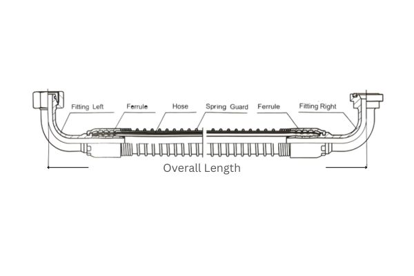
Why are protective measures needed for hose assemblies and what common types are available?
Protective measures are essential to prevent external abrasion and environmental damage, with common options including spring guards (RS), nylon sleeves (NS), stainless steel braided sleeves (SSX), and fire protection sleeves (FP) selected based on the specific operating environment.