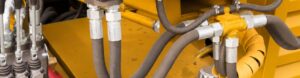
Hydraulic seals play a pivotal role in the efficiency and reliability of fluid power systems. These seemingly simple components are engineering marvels that prevent fluid leakage, maintain pressure, and ensure the smooth operation of hydraulic machinery. Without effective sealing, even the most powerful hydraulic systems would fail to function properly.
Understanding Hydraulic Seal Classifications
Hydraulic seals can be categorized in several ways, depending on the specific criteria used for classification. Understanding these classifications is essential for proper selection and application.
Classification by Pressure Rating
Pressure capability is a fundamental way to categorize hydraulic seals:
- Low-pressure seals (typically up to 5 MPa or 725 psi): These seals are commonly found in light-duty hydraulic systems such as automotive power steering or basic industrial equipment. They’re often made from standard nitrile rubber (NBR) or other general-purpose elastomers.
- Medium-pressure seals (5-16 MPa or 725-2,320 psi): Used in general industrial hydraulics, construction equipment, and agricultural machinery. These seals typically incorporate reinforcement elements and may use higher-grade elastomers or thermoplastic materials.
- High-pressure seals (16-40 MPa or 2,320-5,800 psi): Found in heavy industrial applications, injection molding machines, and mobile hydraulics. These seals often feature anti-extrusion rings, specialized geometries, and higher-performance materials like polyurethane.
- Ultra-high-pressure seals (40-100 MPa or 5,800-14,500 psi): Used in specialized equipment like hydraulic presses, metal forming machinery, and high-pressure test equipment. These sophisticated seals incorporate multiple backup rings, specialized profiles, and advanced materials.
- Super-high-pressure seals (above 100 MPa or 14,500 psi): Reserved for extreme applications like waterjet cutting, isostatic pressing, and specialized testing equipment. These seals represent the cutting edge of sealing technology, often using composite materials, metal-reinforced designs, and precision-engineered geometries.
The appropriate seal selection depends on your system’s operating pressure requirements, with material composition and design changing significantly across these categories. Engineers must consider not just nominal pressure ratings but also pressure spikes, which can momentarily exceed normal operating pressures by 50% or more in some systems.
Classification by Temperature Range
Temperature capability is another critical factor in seal selection:
- Low-temperature seals (below -20°C or -4°F): Special formulations are required to maintain flexibility at low temperatures. Materials like silicone, fluorosilicone, or specially compounded polyurethanes are common choices.
- Standard-temperature seals (-20°C to 100°C or -4°F to 212°F): This is the most common operating range, where standard nitrile (NBR), hydrogenated nitrile (HNBR), and polyurethane materials perform well.
- High-temperature seals (100°C to 200°C or 212°F to 392°F): Applications like steel mill hydraulics or equipment near heat sources require special materials such as fluorocarbon (FKM), ethylene propylene (EPDM), or perfluoroelastomers (FFKM).
- Extreme-temperature seals (above 200°C or 392°F): These specialized seals use exotic materials like polytetrafluoroethylene (PTFE), polyimide, or even metal in some cases.
Static Seals: When Components Don’t Move
Static seals are used between components that don’t move relative to each other. Their effectiveness is measured by achieving zero leakage. These seals are further divided into planar (axial) seals and cylindrical (radial) seals.
In planar sealing, if fluid pressure acts on the inner diameter of the seal ring with leakage flowing outward, it’s called an “internal pressure external flow” configuration. Conversely, if fluid pressure acts on the outer diameter with leakage flowing inward, it’s an “external pressure internal flow” configuration. Understanding this distinction is crucial for proper seal installation, as reversed installation can lead to immediate failure.
Static seals are extensively used in fixed joining surfaces of hydraulic components and in pipe connections throughout hydraulic systems. They represent approximately 40% of all hydraulic seals by volume but account for over 70% of leak-related system failures when improperly selected or installed.
Common Types of Static Seals
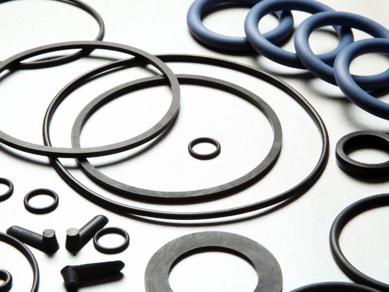
The O-ring is the most widely used static seal due to its simplicity and effectiveness. Consisting of a simple elastomeric torus, O-rings create a seal when compressed between two surfaces, with the compression causing the elastomer to flow and fill surface imperfections. When used in pump suction ports, careful attention must be paid to the installation method. Improper installation can result in the O-ring being sucked into the system or allowing air to enter, both of which can damage the hydraulic system.
The effectiveness of an O-ring depends on several factors:
- Compression ratio: Typically 15-30% of the original cross-section
- Groove design: Must provide proper support while allowing for thermal expansion
- Surface finish: Typically 16-32 microinches Ra for dynamic applications, 32-63 microinches Ra for static applications
- Material compatibility: Must be compatible with the hydraulic fluid and operating environment
Other Static Seal Types
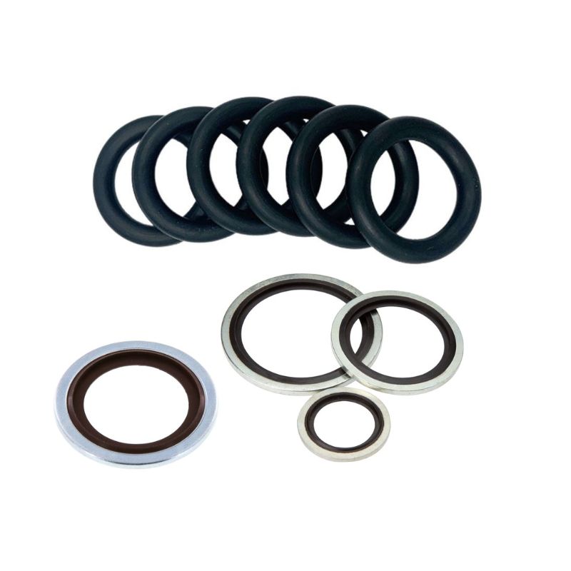
Gasket seals
Used for large diameter connections (typically over 32mm or 50mm) with flanged joints. These can be made from various materials including compressed fiber, rubber, metal, or composite materials. The gasket material must be selected based on pressure, temperature, and chemical compatibility requirements. Metal gaskets, for instance, can handle extreme temperatures but require higher bolt loads and smoother flange surfaces.
Threaded connection gasket seals
Placed in gaps or at the ends of internal threads. These seals compensate for the inherent leakage paths in threaded connections. The material selection depends on pressure and temperature conditions, with options ranging from simple elastomeric washers to complex metal-reinforced composites.
Thread tape or sealant connections
Primarily for tapered threads, ensuring sealing by applying sealant or wrapping tape on male threads. PTFE tape (commonly called “plumber’s tape”) is rated for different pressure ranges by thickness and density, with color coding often indicating the intended application. Liquid thread sealants offer advantages in high-vibration environments where tape might unravel.
Tapered surface seals
Common in low-pressure systems with copper tubing. The soft copper deforms against a harder tapered surface, creating a metal-to-metal seal. In ultra-high-pressure applications, similar principles apply but with steel tubing and copper gaskets to create the seal.
Compression fitting seals
Like ferrule tube fittings that grip and seal by compression. These fittings use one or more ferrules that deform when compressed, creating both a mechanical grip on the tube and a seal. They’re widely used in instrumentation and high-pressure applications due to their reliability and resistance to vibration.
Thread sealant adhesives
Modern anaerobic adhesives that cure in the absence of oxygen when confined between metal surfaces. These products fill the microscopic gaps between threads, hardening to form a plastic seal that can withstand moderate pressures. They’re particularly useful for fine threads where the gap is small (0.1-0.3mm).
Dynamic Seals: Managing Movement and Pressure
Dynamic seals operate between surfaces with relative motion. They’re categorized as reciprocating seals or rotary seals, depending on whether the movement is linear or rotational.
Reciprocating seals are further divided into bore seals (where the seal contacts the bore surface) and rod seals (where the seal contacts the rod surface). This distinction is crucial because the challenges differ significantly between the two:
- Rod seals must prevent pressurized fluid from escaping to the atmosphere while allowing the rod to move freely. They typically have asymmetric profiles designed to seal better in one direction.
- Bore seals (often called piston seals) must contain pressure on both sides while allowing movement. They typically have more symmetric designs and often work in pairs to seal pressure in both directions.
Dynamic seals can also be classified as contact seals or non-contact seals based on whether the sealing element physically touches the sealing surface.
Contact-Type Dynamic Seals
Contact seals rely on the sealing element pressing firmly against the sealing surface. This contact force often increases with fluid pressure, creating a thin oil film between surfaces. These seals are generally limited by friction and wear considerations, restricting their use in high-speed or extremely high-pressure applications.
The PV factor (pressure × velocity) is a critical consideration for contact seals. Each seal material has a maximum PV value beyond which excessive heat generation leads to rapid deterioration. For example, standard nitrile rubber might have a PV limit of 0.5 MPa × m/s, while a PTFE compound might handle 3.5 MPa × m/s or more.
Contact seals are further divided into compression seals and lip seals:
- Compression seals work by compressing soft, elastic packing material in a stuffing box, causing it to expand radially and create a seal. The compression is typically adjustable via gland nuts or bolts, allowing for compensation as the packing wears. Modern versions often use V-shaped or chevron packing rings that naturally expand under pressure.
- Self-sealing designs use specially formed elastic materials like synthetic resins or rubber to fill leakage paths, with sealing effectiveness that increases with fluid pressure. These designs often feature a lip or flexible element that deflects under pressure to increase contact force proportionally.
For high-pressure applications or situations with faster relative motion, combination seals using different materials may be employed to leverage specific material properties like low friction coefficients and elasticity. A common example is a polyurethane seal with PTFE facing elements, combining the excellent sealing properties of polyurethane with the low friction of PTFE.
Modern contact seals often incorporate:
- Wear rings to prevent metal-to-metal contact between moving parts
- Energizing elements like O-rings or springs to maintain contact force
- Anti-extrusion rings to prevent seal material from being forced into clearance gaps
- Special surface treatments on the dynamic surface to optimize the friction-wear balance
Non-Contact Dynamic Seals
Non-contact seals maintain a small gap between sealing surfaces. Their primary advantages include:
- No contact between sealing surfaces
- No friction
- Minimal wear
- Lower starting power requirements
- Longer service life
The main disadvantage is reduced sealing effectiveness compared to contact seals. Non-contact seals typically allow a controlled amount of leakage, which is often acceptable or even beneficial in certain applications.
Non-contact seals include labyrinth seals, floating ring seals, dynamic seals, magnetic fluid seals, and clearance seals. In hydraulic technology, clearance seals are most commonly used, while other non-contact seal types are rarely employed.
Labyrinth seals create a tortuous path for fluid to navigate, with each change in direction and cross-section creating resistance to flow. They’re completely non-contacting and extremely durable but allow more leakage than other options. Modern labyrinth designs often incorporate abradable materials that wear in during initial operation to create tighter clearances.
Floating ring seals use a ring that “floats” between the housing and shaft, maintaining a small clearance on both sides. The ring position self-adjusts based on pressure differentials, optimizing the clearance for different operating conditions.
Dynamic seals use the motion itself to create pressure that opposes leakage. Spiral grooves or pumping features can be designed to drive fluid back toward the high-pressure side during operation.
Installation Best Practices
Proper installation is critical for hydraulic seal performance and system reliability. Even the highest quality seals will fail prematurely if installed incorrectly. This comprehensive guide covers essential installation techniques, common pitfalls, and professional best practices to ensure optimal seal performance.
Pre-Installation Preparation
Thorough preparation is essential for successful seal installation:
Component Verification
- Verify correct seal type, size, and material for the application
- Check seal dimensions against groove specifications
- Inspect new seals for manufacturing defects, shipping damage, or contamination
- Verify seal material compatibility with system fluid and operating conditions
- Check expiration dates on elastomeric seals (some have limited shelf life)
Surface Preparation
- Clean all components thoroughly with appropriate solvents
- Remove all traces of old sealing material and adhesives
- Inspect metal surfaces for:
- Scratches (maximum acceptable depth typically 0.8 μm)
- Nicks or dents
- Corrosion or pitting
- Burrs, especially at drilled holes and machined edges
- Measure and verify critical dimensions:
- Groove depth and width (typically ±0.05mm tolerance)
- Bore diameter and cylindricity
- Rod diameter and straightness
- Chamfer angles and dimensions
- Verify surface finish requirements:
- Dynamic sealing surfaces: 0.1-0.4 μm Ra
- Static sealing surfaces: 0.8-1.6 μm Ra
- Groove surfaces: 1.6-3.2 μm Ra
Detailed Installation Techniques by Seal Type
Different seal types require specific installation approaches:
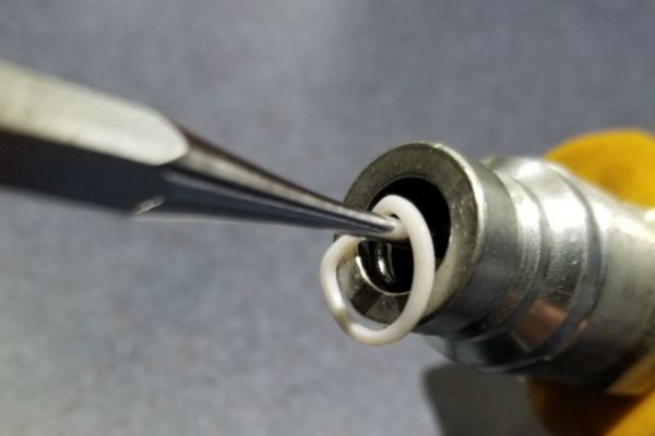
O-Ring Installation
- Lubricate the O-ring with compatible system fluid
- For static applications:
- Stretch the O-ring only as much as necessary to position it
- Never roll the O-ring into place as this can introduce twist
- Ensure the O-ring is seated evenly in the groove without pinching
- For dynamic applications:
- Use installation sleeves with 15-30° tapered lead-in
- Avoid stretching O-ring over sharp threads or keyways
- Verify O-ring is not twisted after installation (use marking if necessary)
- For face seals:
- Ensure O-ring doesn’t slip out of position during assembly
- Tighten fasteners in cross-pattern sequence to ensure even compression
- Use calibrated torque to prevent over-compression
Lip Seal Installation
- Verify correct orientation (lip typically faces pressure side)
- Use appropriate-sized installation tool matching the seal OD
- Apply even pressure around circumference during installation
- Ensure metal case is fully seated against housing shoulder
- Verify lip is not folded or damaged after installation
- For spring-loaded lip seals, confirm spring is properly positioned
U-Cup and V-Ring Installation
- Verify correct orientation (open side typically faces pressure)
- Use tapered installation sleeves for rod seals
- For stack arrangements, maintain correct sequence and orientation
- Ensure backup rings are properly positioned relative to seal
- Verify even seating in groove after installation
Wiper/Scraper Installation
- Install after all other seals are in place
- Ensure correct orientation (scraping edge faces contamination side)
- For press-fit wipers, use appropriate installation tool matching wiper OD
- For snap-in wipers, ensure complete engagement in groove
- Verify scraping edge is not damaged during installation
PTFE Seal Installation
- Handle with extra care due to limited elasticity
- For split PTFE seals, ensure mating ends align properly
- For one-piece PTFE seals on rods:
- Use specialized expanding tools or sizing techniques
- Allow appropriate recovery time after stretching
- For PTFE piston seals:
- Use compression tools to reduce diameter temporarily
- Ensure energizing element (O-ring) is properly positioned
- Allow 24-48 hours break-in period before full pressure operation
Advanced Installation Techniques
Professional installers employ these advanced techniques for challenging installations:
Thermal Assistance
- Warming elastomeric seals (40-50°C) increases flexibility for easier installation
- Cooling metal components can provide temporary clearance for tight fits
- Temperature differential installation for interference fits
- Never heat seals beyond material temperature limits
Staged Assembly
- Pre-assemble seal components before installation when possible
- Use partial assembly techniques for complex seal arrangements
- Install multiple seals in proper sequence to prevent damage
- Use guide pins or alignment fixtures for critical components
Specialized Approaches
- Split seal designs for difficult-to-access locations
- In-situ vulcanizing for custom applications
- Controlled-rate hydraulic or pneumatic pressing for precise installation
- Computer-guided installation for critical high-precision applications
Common Installation Errors and Prevention
Understanding common errors helps prevent installation failures:
Improper Groove Dimensions
- Error: Using incorrect groove dimensions for the seal type and size
- Prevention: Verify groove specifications against manufacturer’s recommendations
- Detection: Measure groove dimensions with precision tools before installation
- Correction: Machine groove to correct dimensions or select appropriate seal for existing groove
Surface Damage
- Error: Installing seals against scratched, pitted, or rough surfaces
- Prevention: Inspect and repair surfaces before installation
- Detection: Use surface profilometer or visual inspection with magnification
- Correction: Polish, hone, or replace damaged components
Contamination
- Error: Installing seals in dirty environments or with contaminated lubricant
- Prevention: Clean all components and work in controlled environment
- Detection: Visual inspection under good lighting
- Correction: Clean and reinstall if contamination is detected
Incorrect Orientation
- Error: Installing directional seals backward
- Prevention: Verify orientation before installation, mark direction if necessary
- Detection: Functional testing or visual inspection
- Correction: Remove and reinstall with correct orientation
Installation Damage
- Error: Cutting or nicking seals during installation
- Prevention: Use proper installation tools and protection sleeves
- Detection: Visual inspection after installation
- Correction: Replace damaged seals immediately
Conclusion
Mastering hydraulic sealing technology isn’t just about learning the basics—it’s about continually applying best practices and evolving with industry needs. Connect with our team today to schedule a no-obligation consultation and discover how we can help your operation achieve lasting excellence in hydraulic fitting sealing.
FAQ
What’s the main difference between static and dynamic seals?
Static seals are used between non-moving components while dynamic seals accommodate relative motion between parts.
Why are O-rings so widely used in hydraulic systems?
O-rings offer simplicity, effectiveness, and versatility across a wide range of pressures and applications.
What advantage do non-contact seals have over contact seals?
Non-contact seals eliminate friction and wear, providing longer service life and lower power requirements.
How do self-sealing designs work?
They utilize fluid pressure itself to increase sealing force, becoming more effective as system pressure rises.
What’s the purpose of auxiliary seals in a hydraulic system?
They protect primary seals from damage, enhance sealing performance, and extend overall system life.
When would you choose a clearance seal over a contact seal?
When applications require minimal friction, long service life, and can tolerate slight leakage.