Tractor lift cylinders fail during peak working seasons due to extreme mechanical fatigue, structural overloading, internal oil contamination, and severe environmental breakdown. When your equipment handles continuous payloads under unforgiving fieldwork conditions, minor hidden component damage rapidly accelerates into catastrophic seal or structural failure. Understanding the engineering reasons behind these breakdowns is the only real-world way to diagnose hydraulic issues accurately, perform reliable mechanical maintenance, and implement preventative engineering strategies to secure your peak seasonal uptime.
Why Does Extreme Operational Overloading Trigger Sudden Lift Failure?
Extreme operational overloading triggers sudden lift failure by forcing internal system pressures far past the specified structural limits of your equipment. When you attempt to lift payloads exceeding the safe working load capacity, the mechanical stress distorts key components and blows out vital pressure boundaries.
- Structural Pressure Spikes: Attempting to force an oversized payload out of the ground creates an intense spikes in system pressure that instantly shreds high-pressure rubber seals and deforms heavy internal steel piston heads.
- Mechanical Cross-Section Failure: Heavy structural loads applied at extreme working angles place severe bending stresses on the piston shafts, forcing them completely out of their tight dimensional alignment.
The structural integrity of the entire component drops to zero, making a full mechanical rebuild or replacement your only remaining path forward.
What Are The Structural Load Limits Of Utility Components?
Utility components are precisely engineered to operate within clear geometric and pressure envelopes to guarantee reliable field performance. Exceeding these engineering thresholds causes immediate plastic deformation of the high-strength steel housings and destroys tight internal running clearances.
- Bore Expansion Material Limits: Continuous over-pressurization stretches the outer seamless steel cylinder tube wall, allowing high-pressure fluid to bypass the internal piston head.
- Mounting Pin Shear Points: Heavy axial shock loads transfer directly onto the rear clevis and front rod-end mounting pins, causing severe structural fatigue and eventual mechanical failure.
As the mounts deform under heavy payloads, the component suffers from severe stroke misalignment, which rapidly ruins new replacement parts.
| Component Spec Metric | Standard Operating Limits | Peak Failure Thresholds |
| System Operating Pressure | 2,500 PSI – 3,000 PSI | Exceeds 4,500 PSI Spikes |
| Rod Structural Straightness | < 0.002 Inches per Foot | > 0.015 Inches Bend Failure |
| Fluid Cleanliness Target | ISO 18/16/13 Standard | ISO 22/20/17 Contaminated |
How Does Hydraulic Oil Contamination Destroy High-Pressure Seals?
Hydraulic oil contamination destroys high-pressure seals by turning the circulating fluid into an aggressive, abrasive slurry that continuously scores polished internal metallic surfaces. As fine solid particulate matter migrates throughout your system, it actively grinds down every single critical sealing edge.
- Abrasive Edge Degradation: Microscopic dirt, silica, and metallic particles wedge themselves between the rubber lips and the moving shaft, tearing away the critical sealing boundary.
- Internal Material Silt Lock: Fine particulate contamination accumulates within the close-tolerance internal valve pathways, causing severe pressure imbalances and erratic lift performance.
If you do not maintain strict fluid cleanliness standards, no replacement seal kit will ever survive past a few intense operational cycles.
Why Do Particulate Contaminants Multiply During Harvest Seasons?
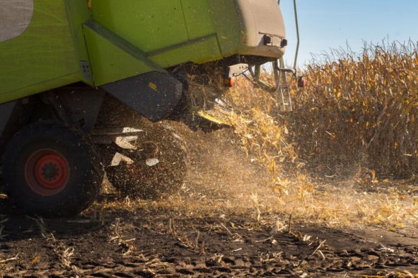
Harvest seasons introduce an overwhelming volume of airborne dust, chaff, and ambient agricultural debris directly into your daily operational environment. This particulate matter settles heavily onto every exposed machine component, waiting for a path to enter the closed fluid loop.
- Rod Wiper Exclusion Failures: Damaged or weathered external rod wiper seals allow abrasive field dust to cling to the wet chrome shaft and slip straight past the main gland.
- Open Reservoir Ingress Routes: Neglected hydraulic reservoir breathers and worn filler cap gaskets draw heavily contaminated ambient air directly into the main storage tank during deep cycling.
Every single stroke of a dirty chrome rod drags thousands of abrasive micro-particles deep into your high-pressure fluid lines.
| Contamination Type | Primary Ingress Point | Component Damage Mechanism |
| Silica Field Dust | Worn Gland Rod Wipers | Scores Polished Chrome Shafts |
| Metallic Wear Debris | Internal Pump Fatigue | Shreds Polyurethane Rod Seals |
| Microscopic Crop Fiber | Open Reservoir Vents | Clogs High-Pressure Valve Ports |
Why Does Extreme Seasonal Heat Cause Catastrophic Fluid Breakdown?
Extreme seasonal heat causes catastrophic fluid breakdown by reducing the operating oil viscosity far below the minimum film thickness required to protect moving metallic parts. When temperatures soar during peak summer operations, the fluid completely loses its structural capability to withstand extreme pressures.
- Lubricating Film Thinning: High ambient temperatures combined with heavy continuous workloads drive fluid temperatures past stable operating limits, causing severe internal component scuffing.
- Accelerated Rubber Oxidation: Operating in high thermal zones bakes the internal nitril or polyurethane compounds, turning flexible rubber seals incredibly brittle and prone to cracking.
Once your hydraulic oil undergoes severe thermal degradation, it begins to actively destroy your internal system components from the inside out.
How Do Thermal Cycles Fatigue Heavy Industrial Components?
Continuous cycling between extreme daytime operational heat and cold night ambient temperatures subjects your equipment to severe volumetric expansion and contraction. This perpetual thermal movement fatigues every single threaded joint and material junction.
- Gland Nut Torque Loss: Alternating thermal expansion cycles loosen the heavy threaded gland retaining caps, leading to unexpected external fluid leaks around the rod nose.
- Piston Seal Material Extrusion: Excessive heat softens the backing rings of your internal seals, forcing the pliable material into small clearances until it shears completely off.
As the internal seal material breaks apart due to thermal stress, the loose fragments travel down-line to jam delicate hydraulic control valves.
| Thermal Performance Metric | Optimal Operating Range | Extreme Thermal Failure Zone |
| Hydraulic Oil Temperature | 120°F – 140°F | Exceeds 190°F Breakdown |
| Elastomer Seal Hardness | 70 – 90 Shore A | Hardens Past 95 Shore (Brittle) |
| Fluid Kinematic Viscosity | 32 – 46 cSt Standard | Drops Below 10 cSt (Thin) |
How Does Hard Chrome Plating Degradation Lead To Leaks?
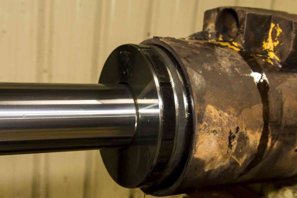
Hard chrome plating degradation leads to leaks by exposing the raw, unprotected base steel of your piston shaft to corrosive ambient elements. Once the ultra-hard outer defensive barrier is compromised, the structural integrity of the moving seal boundary rapidly declines.
- Micro-Crack Moisture Path: Microscopic imperfections within low-grade chrome plating allow moisture to migrate down to the underlying steel, triggering hidden sub-surface corrosion.
- Plating Layer Adhesion Loss: As sub-surface rust expands beneath the protective layer, the hard outer chrome shell blister, cracks, and flakes entirely away from the rod body.
A single flaked area of chrome acts exactly like a razor blade, slicing through your main sealing lips with every stroke.
Why Do Scored Rod Shafts Ruin Brand New Seal Kits?
Scored rod shafts possess sharp, cratered metallic edges that physically carve away the soft sealing lips of polyurethane components upon direct mechanical contact. Installing fresh rubber components over a damaged chrome surface provides nothing more than a very temporary cosmetic fix.
- Sealing Lip Material Tearing: The rough, jagged profile of a scored metal shaft abrades the tight sealing line, creating an immediate low-pressure leak path.
- Particulate Pocket Trapping: Deep metallic scores collect abrasive field grime and transport it straight past your external wipers, introducing contaminants into the pressure chamber.
Your newly installed components will fail within a few hours of field operation if the underlying metallic defects are not completely eliminated.
| Shaft Condition Grade | Surface Roughness (Ra) | Expected Sealing Lifespan |
| Premium Plated Chrome | 0.1 – 0.2 Microns | 3,000+ High-Pressure Hours |
| Moderate Surface Scoring | 0.8 – 1.2 Microns | Less Than 100 Field Hours |
| Flaking & Severe Pitting | > 2.5 Microns | Immediate Seal Tearing Failure |
What Causes Severe Internal Bypass And Unexpected Lift Drift?
Severe internal bypass and unexpected lift drift are caused by a complete structural failure of the sealing elements located on the main internal piston head. When fluid leaks across this primary internal pressure boundary, the component completely loses its physical ability to hold a static payload.
- Piston Ring Radial Wear: Continuous high-pressure cycling wears down the outer circumference of your internal piston seals, creating an invisible pathway between the two internal chambers.
- Bore Barrel Internal Scoring: Hard particulate contaminants trapped inside the main barrel carve deep longitudinal tracks along the internal walls, rendering the piston rings completely ineffective.
Your loader or implement will slowly and uncontrollably drift downward when your control valves are set to neutral, creating an immediate and severe safety hazard on your farm.
How Do You Isolate Piston Bypass From Control Valve Leaks?
Isolating internal bypass from a failing control valve requires a systematic diagnostic pressure isolation test to pinpoint the exact location of the fluid loss. Mistakenly replacing a perfectly functional component due to a faulty spool valve wastes valuable time and financial resources.
- Mechanical Stroke Isolation Check: Extend the rod fully, safely lock the load structurally, disconnect the return port line completely, and apply full system pressure to the opposite side to check for active fluid bypassing.
- Control Spool Valve Neutral Isolation: Connect high-pressure gauges directly to the cylinder ports and place the main control valve into neutral to see if pressure drops while the loader drifts.
Taking thirty minutes to properly isolate the root cause will save you hundreds of dollars in unnecessary part replacements.
| Diagnostic Test Method | Observed System Symptom | Confirmed Structural Fault Location |
| Port Return Line Disconnect | Continuous Fluid Stream From Port | Blown Internal Piston Head Seals |
| Neutral Spool Pressure Test | Pressure Drops / No Cylinder Bypass | Worn Main Control Spool Valve |
| Visual External Inspection | Oil Accumulation At Gland Cap | Blown External Rod Gland Seals |
How Do Severe Side Loads Accelerate Mechanical Gland Failure?
Severe side loads accelerate mechanical gland failure by focusing immense, concentrated non-axial forces onto one specific side of the rod guide bushing and internal sealing elements. This uneven structural loading rapidly deforms every soft alignment component inside the assembly.
- Guide Bushing Oval Deformation: Persistent lateral forces compress one side of your internal metallic bronze guide bush, turning a precision round bore into an off-center oval.
- Uneven Seal Lip Compression: As the rod shaft shifts off-center under side loads, one side of the rubber seal is crushed completely flat while the opposite side lifts away from the metal.
Your component will begin to leak heavily from the gland nose, and the rod shaft will start to bind violently during its stroke.
What Structural Factors Force Moving Shafts Out Of Axis?
Moving shafts are forced out of their engineered structural axis by worn mounting joints, incorrect machine geometry, or unbalanced front implement configurations. When your mechanical pivot connections develop excessive play, the entire component shifts under heavy loads.
- Clevis Pin Bushing Elongation: Oval-worn mounting eyes and wallowed-out frame bushings allow the entire assembly to twist violently during high-pressure lifting cycles.
- Asymmetrical Implement Torsion: Lifting a heavy payload that is positioned completely on one side of your front loader bucket twists the main lifting arms, inducing severe lateral forces.
No hydraulic component is engineered to act as a structural frame support against intense lateral machine flexing.
| Mechanical Connection Status | Lateral Shaft Deflection | Gland Bushing Wear Rate |
| Precision Factory Alignment | 0.000 Inches deflection | Baseline Standard Wear |
| Worn Frame Pivot Bushings | 0.020 – 0.040 Inches Shift | Multiplies Wear Rate by 5x |
| Bent Loader Frame Structure | > 0.080 Inches Deflection | Immediate Bushing Binding Failure |
Why Do Poor Mechanical Maintenance Habits Invite Seasonal Breakdown?
Poor mechanical maintenance habits invite seasonal breakdown by allowing minor, easily correctable component wear issues to develop into massive system-wide equipment failures. Neglecting your high-pressure systems during the slow months ensures a breakdown during the busiest weeks of the season.
- Grease Zerk Particle Contamination: Failing to regularly purge your mounting pin grease points allows abrasive dirt to lock up the pivot joints, generating severe structural side loads.
- Hydraulic Filter Bypass Operation: Running your system with clogged oil filters forces the main filter assembly into bypass mode, circulating unfiltered, abrasive oil throughout the loop.
You can either invest a small amount of time into basic preventative maintenance now, or pay thousands of dollars for emergency field service later.
How Does Neglecting Water Contamination Corrode Internal Components?
Neglecting water contamination inside your fluid reservoir destroys the vital lubricating properties of your hydraulic oil and triggers widespread internal rust along polished steel barrel walls. Water enters your system through worn reservoir seals or via ambient condensation during thermal cycles.
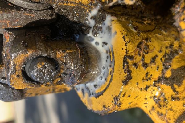
- Fluid Emulsification and Shearing: Excessive internal water content turns your clean hydraulic oil into a milky, foamy emulsion that completely fails to protect high-pressure components from wear.
- Internal Piston Component Pitting: Trapped moisture settles inside the steel barrel during periods of inactivity, eating away at the smooth cross-hatch finish until deep pits form.
Once the inner walls of your steel barrel become pitted with rust, the internal piston seals are shredded to pieces within a few operational strokes.
| Fluid Condition Parameter | Safe Operating Standard | Danger Breakdown Zone |
| Internal Moisture Volume | < 0.05% Water Content | Exceeds 0.20% Water Emulsion |
| Fluid Visual Appearance | Clear Bright Amber Oil | Milky Foamy Cloudy Appearance |
| Filter Differential Pressure | < 15 PSI Resistance | Past 25 PSI (Bypass Engaged) |
How Do Mechanical Shock Loads Tear Heavy Structural Mounts?
Heavy mechanical shock loads tear structural mounts by generating instantaneous, massive kinetic energy transfers that far exceed the ultimate tensile strength of the machine steel. These violent force spikes occur when a moving tractor hits an immovable object while carrying a heavy payload.
- Welded Clevis Joint Cracking: Sudden impact forces travel instantly through the solid steel rod, concentrating massive stress directly onto the rear welded base clevis joint.
- Structural End Cap Thread Stripping: Intense high-pressure spikes generated by heavy front impacts slam the internal piston head against the gland nut, stripping the steel threads completely out.
A structural mount failure at road speeds can drop a heavy implement onto the ground instantly, causing a complete loss of steering control or a major vehicle rollover.
What Farm Scenarios Generate The Highest Kinetic Force Spikes?
The highest kinetic force spikes are generated during high-speed loader operations on rough, uneven terrain or when utilizing front implements to break up hard, compacted soil structures. Operating your machinery aggressively transforms minor obstacles into major structural impacts.
- High-Speed Frozen Ground Impacts: Driving a front loader bucket into a hidden frozen dirt mound at high speed transfers thousands of foot-pounds of kinetic energy directly into the lift arms.
- Unbalanced Rough Pasture Transport: Bouncing heavy round hay bales across deeply rutted pastures at high speeds creates a continuous hammer-effect inside the fluid chambers.
Slowing down on rough ground is the easiest and cheapest way to eliminate destructive structural shock loads from your daily operations.
| Operational Scenario | Estimated Instantaneous Pressure | Primary Component Risk |
| Smooth Farmyard Hay Transport | 2,200 PSI – 2,500 PSI | Normal Structural Wear |
| Rough Pasture Bale Bouncing | 3,800 PSI Pressure Spikes | Fatigue Cracking at Mount Welds |
| High-Speed Earth Impact | > 5,500 PSI Instant Shock | Stripped End Cap / Bent Rod |
How Do You Execute A Precision Field Walkthrough For Rebuilding Cylinders?
Executing a precision field walkthrough for rebuilding cylinders requires a spotlessly clean workspace, specialized mechanical tools, and a methodical, step-by-step assembly process. Ad-hoc, rushed field repairs performed in dirty conditions will always introduce destructive contamination into your system.
- Isolate and Depressurize: Park the vehicle on flat ground, completely lower the front loader arms to relieve all internal pressure, shut down the engine, and actuate the control levers to vent trapped fluid.
- Clean the Outer Assembly: Use heavy-duty degreaser and a wire brush to remove every trace of field grime from the gland cap and hose connections before opening the system.
Carefully document the exact order and orientation of every internal component as you remove it to ensure a flawless reassembly.
What Precision Techniques Prevent Introducing Damage During Reassembly?
Precision techniques during reassembly include utilizing soft installation tools, heavily lubricating every rubber component with clean hydraulic oil, and matching exact manufacturer torque specifications. Forcing components together with crude hand tools will instantly ruin your new parts.
- Internal Sharp Thread Protection: Wrap plastic tape over the sharp metallic rod implement mounting threads to prevent cutting the delicate inner lips of your new gland seals during installation.
- Methodical Cross-Hatch Inspection: Thoroughly check the inner steel barrel walls for deep scoring or corrosion pits, and use a flexible ball hone to restore the clean cross-hatch finish if minor blemishes exist.
Manually cycle the rebuilt assembly and check for smooth stroke movement and absolute zero fluid weeping before reinstalling it onto your tractor frame.
| Rebuild Step Sequence | Critical Action Required | Precision Mechanical Goal |
| Step 1: External Grime Wash | Degrease Entire Gland Area | Prevent Particle Contamination |
| Step 2: Thread Tape Shield | Wrap Sharp Mounting Threads | Prevent Tearing New Seal Lips |
| Step 3: Gland Nut Torquing | Torque to OEM Spec (Ft-Lbs) | Prevent Gland Cap Loosening |
Summary
Eliminating premature equipment failure during your busiest harvest weeks requires a complete transition from reactive, emergency repairs to a strict routine of proactive asset preservation. By deeply understanding how operational overloading, fluid contamination, and mechanical misalignment combine to destroy your machinery, you can easily stop major breakdowns before they start. Implementing a systematic daily inspection routine, enforcing strict oil cleanliness standards, and prioritizing precision-machined replacement components are your most effective field strategies to guarantee uninterrupted seasonal operations.
Frequently Asked Questions
Can I repair a bent cylinder rod back to straight?
No, you should never attempt to straighten a bent rod because mechanical press operations introduce severe micro-fractures into the steel alloy and permanently ruin the hard chrome plating. The distorted metal will possess major structural weaknesses that cause it to bend again under normal loads, and the uneven surface will instantly tear your main gland seals. Always replace a bent rod completely to ensure safe and reliable machinery operations.
What’s the best way to clean a pitted rod in the field?
The best temporary field fix for minor surface pitting is to very carefully polish the shaft using 600-grit wet-and-dry sandpaper lubricated heavily with fresh hydraulic oil. You must use incredibly light, circular strokes to smooth down the raised, sharp metallic edges of the pits without grinding flat spots into the round chrome profile. If the pitting is deep enough to catch your thumbnail, the rod cannot be saved and must be replaced to stop chronic fluid leaks.
How do I know if my cylinder leak is internal or external?
An external leak is immediately obvious because high-pressure hydraulic oil will actively weep or spray past the gland nut cap, leaving a visible fluid residue on the machine frame. An internal leak has no visible external signs but causes the tractor lift arms to slowly drift downward when the control valve is held in neutral. You can confirm internal bypass by completely disconnecting the return port line and checking for active fluid bypassing when pressure is applied.
How often should I change my hydraulic fluid and filters?
You should replace your hydraulic system return filters every 250 operating hours and perform a full system fluid flush every 1,000 hours under standard agricultural working conditions. If you operate your machinery in extremely dusty fields or under continuous heavy payloads, you must cut these service intervals completely in half. Regularly tracking your operational hours and performing scheduled filter changes is the most effective way to eliminate destructive oil contamination.
Can I use a larger capacity cylinder to stop frequent bending?
No, you must never install a larger capacity cylinder onto your machinery without first verifying that the tractor frame and structural loader arms can handle the increased mechanical forces. A larger bore component will generate massive lifting forces that can easily twist your loader linkage, crack the main frame mounts, or trigger dangerous vehicle instability. The correct solution is to eliminate side loading, maintain pivot pins, and operate within factory payload limits.