Understanding Metric Pipe Fitting Sizes A Quick Reference

Understanding Metric Pipe Fitting Sizes: A Quick Reference

Understanding Metric Pipe Fitting Sizes: A Quick Reference

Introduction

Metric pipe fitting sizes are a standardized system used globally in various industries, such as plumbing, automotive, and manufacturing, for connecting pipes and tubes. These fittings are essential for ensuring compatibility and efficiency in systems that rely on precise fluid or gas flow. The history of metric pipe fittings dates back to the push for international standardization, which aimed to simplify global trade and manufacturing processes. This guide is designed to help you understand metric pipe fitting sizes, offering a quick and easy reference for accurate and reliable installations.

Basics of Metric Pipe Fitting Sizes

Metric pipe fittings are components used to connect sections of pipe or tubing in systems that require the precise conveyance of fluids or gases. These fittings are measured using the metric system, which is based on meters and millimeters. This standardization allows for consistent and accurate sizing, ensuring that parts from different manufacturers can fit together seamlessly.

Common Materials Used

Metric pipe fittings are manufactured from a variety of materials, each chosen for its specific properties and suitability for different applications. Common materials include:

Brass: Known for its durability and resistance to corrosion, brass is often used in plumbing and heating applications.

Stainless Steel: Valued for its strength and resistance to rust and corrosion, stainless steel fittings are ideal for high-pressure and high-temperature environments.

Plastic: Lightweight and resistant to chemical corrosion, plastic fittings are commonly used in residential plumbing and irrigation systems.

Why Metric?

Using metric fittings offers several advantages compared to imperial fittings. One key advantage is the ease of measurement and calculation. The metric system is based on units of ten, which simplifies conversions and reduces the likelihood of errors during design, manufacturing, and installation. Additionally, metric fittings often provide more precise measurements, which is critical in applications requiring high accuracy.

Global Standardization and Its Benefits

Global standardization through the metric system offers significant benefits, particularly in international trade and manufacturing. With metric fittings, companies can source components from around the world without worrying about compatibility issues, as the sizes are universally recognized. This standardization facilitates smoother supply chains, reduces inventory complexity, and ensures that products meet international quality standards.

Understanding Measurements

How Metric Pipe Fittings Are Measured

Metric pipe fittings are measured using the metric system, typically in millimeters (mm). The key dimensions measured include the outer diameter (OD) and the inner diameter (ID) of the pipe, as well as the thread size if applicable. These measurements are critical for ensuring a proper fit and reliable performance in the assembled system.

Diameter: The diameter of a pipe fitting is one of its most crucial measurements. The outer diameter (OD) is the measurement across the widest point of the fitting, while the inner diameter (ID) is the measurement of the open space inside the fitting. These measurements ensure that the pipe and fitting will fit together properly.

Thread Size: For threaded fittings, the thread size is another essential measurement. This includes the pitch (the distance between threads), the thread angle, and the major diameter (the outer edge of the threads). Accurate thread measurements ensure a secure and leak-free connection.

Other Measurements: Additional measurements that may be important depending on the application include the wall thickness of the pipe (which affects its strength and flow capacity) and the overall length of the fitting. These measurements help in designing systems that are both efficient and durable.

Topa metric hydraulic fitting Manufacturer in China Topa

Types of Metric Pipe Fittings

Straight Fittings

Straight fittings, also known as straight connectors or couplings, are used to connect two sections of pipe or tubing in a straight line. They provide a secure and leak-proof connection, ensuring the continuous flow of fluids or gases without any change in direction. These fittings are commonly used in plumbing, hydraulic, and pneumatic systems, as well as in various industrial applications where a direct, uninterrupted pipeline is required.

Common Sizes and Variations

Straight fittings come in a variety of sizes to match the outer diameter (OD) of the pipes they are connecting. Common sizes include 6 mm, 8 mm, 10 mm, 12 mm, 16 mm, and 20 mm. Variations include different thread types (e.g., BSP, NPT) and configurations, such as male-to-male, female-to-female, and male-to-female connectors.

Elbow Fittings

Elbow fittings are used to change the direction of a pipeline, typically by 90 degrees or 45 degrees. These fittings are essential in systems where the pipes need to navigate around obstacles or fit into confined spaces. Elbow fittings are widely used in plumbing, heating, and cooling systems, as well as in industrial piping networks.

Common Sizes and Variations

Common sizes for elbow fittings include 10 mm, 15 mm, 20 mm, 25 mm, and 32 mm. Variations include different angles (e.g., 45-degree, 90-degree), as well as short-radius and long-radius elbows. Additionally, elbows can be threaded or socket-welded, depending on the application and required connection type.

Tee Fittings

Tee fittings, also known as T-fittings, are used to connect three sections of pipe or tubing, forming a T-shaped intersection. These fittings allow for the branching off of a pipeline into two separate directions, making them ideal for distributing fluids or gases to multiple locations. Tee fittings are commonly found in plumbing, irrigation, and HVAC systems.

Common Sizes and Variations

Standard sizes for tee fittings include 10 mm, 15 mm, 20 mm, 25 mm, and 32 mm. Variations include equal tees (where all three branches are the same size) and reducing tees (where one or more branches are of different sizes). Tees can also have threaded or socket-welded connections.

Reducer Fittings

Reducer fittings are used to connect pipes of different diameters, allowing for a smooth transition between larger and smaller pipes. These fittings are essential in systems where the flow rate or pressure needs to be adjusted by changing the pipe size. Reducers are commonly used in plumbing, HVAC, and industrial piping systems.

Common Sizes and Variations

Common sizes for reducer fittings include combinations such as 20 mm to 15 mm, 25 mm to 20 mm, and 32 mm to 25 mm. Variations include concentric reducers (which have a symmetrical shape) and eccentric reducers (which have an offset shape to prevent air pockets in horizontal pipelines). Reducers can also be threaded or socket-welded.

Coupling Fittings

Coupling fittings, also known as couplers, are short lengths of pipe used to connect two pipes together. They provide a secure and leak-proof connection, making them ideal for extending the length of a pipeline or repairing a damaged section. Couplings are widely used in plumbing, hydraulic, and pneumatic systems.

Common Sizes and Variations

Standard sizes for couplings include 6 mm, 8 mm, 10 mm, 12 mm, 16 mm, and 20 mm. Variations include full couplings (which join two pipes of the same size) and reducing couplings (which join pipes of different sizes). Couplings can also have threaded or socket-welded connections.

Other Specialized Fittings

Specialized fittings are designed for specific applications and may not be as widely used as standard fittings. These include fittings like crosses, unions, caps, plugs, and flanges:

Crosses: Used to connect four sections of pipe in a cross-shaped intersection. Commonly used in fire sprinkler systems and certain industrial applications.

Unions: Allow for easy disconnection and reconnection of pipes, useful in systems that require regular maintenance or assembly.

Caps and Plugs: Used to close off the ends of pipes, preventing the flow of fluids or gases. Essential for system shutdowns or future expansions.

Flanges: Provide a method for connecting pipes, valves, and other equipment with bolts, allowing for easy assembly and disassembly. Commonly used in high-pressure applications.

Selecting the Right Metric Pipe Fitting Size

Pressure Ratings

Definition: Pressure rating indicates the maximum pressure that a fitting can withstand without failing.

Importance: Ensuring that fittings match the pressure requirements of your system is critical for safety and performance.

Selection Tips: Check the specifications provided by the manufacturer. Always select fittings with a pressure rating equal to or higher than the system’s maximum pressure.

Temperature Ratings

Definition: Temperature rating specifies the range of temperatures that a fitting can endure without degrading.

Importance: Using fittings outside their temperature range can lead to failures such as leaks, material degradation, and system inefficiency.

Selection Tips: Consider the operating temperature of your system and select fittings designed to perform well within that range. For extreme temperatures, specialized fittings may be necessary.

Material Compatibility

Definition: Material compatibility ensures that the fitting material is suitable for the type of fluid or gas being conveyed.

Importance: Incompatible materials can cause corrosion, leaks, and system failures.

Selection Tips: Match the fitting material with the fluid or gas type. For example, stainless steel fittings are excellent for corrosive environments, while brass is suitable for water and air applications.

Metric Pipe Fitting Measurement Tips

Use Calipers for Precision

Digital Calipers: Provide highly accurate measurements of both the outer diameter (OD) and inner diameter (ID) of the pipe fittings. Ensure the calipers are zeroed before use.

Vernier Calipers: Also accurate, but require careful reading. Make sure to calibrate them periodically for consistent accuracy.

Thread Gauges for Threaded Fittings

Thread Pitch Gauges: Used to measure the thread pitch (the distance between threads). Select the gauge that fits snugly into the threads without forcing it.

Thread Diameter Gauges: Measure the major and minor diameters of the threads to ensure compatibility with mating parts.

Measuring Tape for Length

Flexible Measuring Tape: Ideal for measuring the overall length of pipes and fittings, especially when dealing with curved or irregular shapes.

hydraulic fittings measure tools Topa

Proper Measurement Points

Outer Diameter (OD): Measure across the widest point of the fitting. Ensure the caliper is perpendicular to the fitting to avoid inaccurate readings.

Inner Diameter (ID): Measure the open space inside the fitting. Ensure the caliper tips touch the inner walls without deforming the fitting.

Thread Size: Measure both the major and minor diameters of the thread. For male threads, measure the outermost points, and for female threads, measure the innermost points.

Practical Tips for Accurate Measurement

Ensure Cleanliness

Clean Fittings: Before measuring, clean the fittings thoroughly to remove any debris, oil, or dirt that could affect the measurement.

Dry Surfaces: Make sure the surfaces are dry to prevent slippage of measuring tools.

Avoid Deformation

Gentle Handling: Handle fittings gently to avoid deforming them during measurement. Deformation can lead to inaccurate readings.

Correct Tool Pressure: Apply consistent, gentle pressure when using calipers to avoid compressing the material.

Measure Multiple Times

Consistency Check: Measure each fitting multiple times to ensure consistency. Record each measurement and take the average to account for any minor discrepancies.

Different Angles: Measure from different angles to confirm uniformity, especially with threaded fittings.

Account for Tolerances

Manufacturer Specifications: Refer to manufacturer specifications for acceptable tolerances. Metric fittings are manufactured within certain tolerance ranges to ensure compatibility.

Fit and Function: Ensure that the measured dimensions fall within these tolerances to guarantee proper fit and function.

Use Appropriate Tools

Calibrated Instruments: Ensure all measuring instruments are calibrated regularly to maintain their accuracy.

Specialized Tools: Use specialized tools like micrometers for high-precision measurements if needed.

Tips for Ensuring a Proper Fit

Match the Sizes

Correct Diameter: Ensure the outer diameter of the pipe matches the inner diameter of the fitting for a snug fit.

Thread Compatibility: Verify that the thread pitch and diameter match between the fitting and the pipe.

Use Sealing Materials

Teflon Tape: Wrap Teflon tape around male threads to ensure a tight seal and prevent leaks.

Pipe Dope: Apply pipe dope (thread sealant) on threads to enhance sealing, especially in high-pressure applications.

Check for Alignment

Proper Alignment: Ensure that the pipes and fittings are properly aligned to avoid stress and potential leaks at the joints.

Support Systems: Use supports and brackets to maintain alignment and prevent sagging or misalignment over time.

Avoid Over-tightening

Tightening Technique: Tighten fittings until they are snug, then apply an additional quarter turn. Over-tightening can strip threads and cause leaks.

Regular Inspection and Maintenance

Routine Checks: Regularly inspect fittings for signs of wear, corrosion, or leaks.

Timely Replacement: Replace any worn or damaged fittings promptly to maintain system integrity.

Conclusion

In summary, understanding metric pipe fitting sizes involves knowing how to measure accurately, considering factors like pressure, temperature, and material compatibility, and using the correct tools and techniques for a secure installation. By following these guidelines, you can ensure efficient and reliable piping systems. For further reading and additional resources, refer to industry standards and guides. If you need expert advice or support, please contact us!

FAQ

What are metric pipe fittings?

Metric pipe fittings are components used to connect pipes or tubes in hydraulic, plumbing, and various other systems, measured using the metric system.

Why should I use metric fittings over imperial fittings?

Metric fittings provide easier and more precise measurements, facilitating global standardization and compatibility across different manufacturers.

How do I measure the size of a metric pipe fitting?

Use calipers to measure the outer diameter (OD) and inner diameter (ID), and thread gauges to determine thread size and pitch.

What materials are common for metric pipe fittings?

Common materials include brass, stainless steel, and plastic, each selected based on their properties and suitability for specific applications.

How do I ensure a proper fit for metric pipe fittings?

Ensure cleanliness, use appropriate sealing materials like Teflon tape, and avoid over-tightening. Align pipes correctly and check for consistency in measurements.

Where can I find more information or support for selecting metric pipe fittings?

Refer to industry standards, and manufacturer’s guides, or contact expert support for personalized advice and further resources.

What Does NPT Mean in Plumbing System?

What Does NPT Mean in Plumbing System

What Does NPT Mean in Plumbing System?

Introduction

It’s crucial to understand the concept of NPT because it’s a common standard used in plumbing systems to ensure a leak-proof seal in your plumbing system. This article will take a comprehensive look at NPT threads, explaining what they are, what they mean in the plumbing industry, and how they are used in various applications.

Understanding NPT

Definition of NPT

NPT, or National Pipe Tapered threads, is a standardized threading system used in plumbing and piping applications to ensure a secure, leak-proof connection. The term “National Pipe Tapered” indicates that the threads are tapered, meaning they gradually decrease in diameter along the length of the thread. This tapering allows for a tighter seal as the threads are screwed together, which is critical for preventing leaks in fluid and gas systems.

NPT fitting guide Topa

Historical Background and Development of NPT Standards

The NPT standard originated in the United States in the late 1800s during the industrial revolution, a time when the need for standardized piping systems became increasingly important due to rapid industrial growth. Before the establishment of NPT, there was a lack of uniformity in pipe threads, which led to frequent leaks and failures in piping systems. Engineers and industry leaders recognized the need for a consistent standard, which led to the development of NPT threads.

Technical Specifications

The tapered design of NPT threads is a key feature that distinguishes them from other types of pipe threads. The taper of NPT threads is designed at an angle of 1°47′ from the center axis. This design causes the diameter of the threads to decrease gradually along the length of the pipe, allowing the threads to form a tighter, more secure fit as they are engaged.

When two NPT-threaded components are screwed together, the taper causes the threads to compress and form a seal. This mechanical seal is enhanced when a thread sealant, such as PTFE tape or pipe dope, is applied to the threads before assembly. The sealant fills any small gaps between the threads, further preventing leaks.

The Role of NPT in Plumbing

Functionality of NPT Threads

NPT threads are specifically designed to create a tight, leak-proof seal through their unique tapered structure. As the threads of a male NPT component are screwed into a female NPT component, the taper causes the threads to compress against each other. This compression increases the surface contact between the threads, which helps to form a mechanical seal. Additionally, the use of thread sealants, such as PTFE tape (commonly known as Teflon tape) or pipe dope, enhances this seal by filling in any small gaps between the threads. The combination of the mechanical fit and the sealant ensures a secure, leak-proof connection that is essential in plumbing applications where fluid or gas leakage must be prevented.

Comparison with Straight Threads

Unlike NPT threads, straight threads (often referred to as parallel threads) maintain a consistent diameter along their entire length. While straight threads can provide a strong mechanical connection, they do not inherently create a seal. For straight threads to be leak-proof, additional sealing mechanisms, such as O-rings or gaskets, are typically required. In contrast, the tapered design of NPT threads eliminates the need for these additional sealing elements, as the taper itself creates the necessary compression to form a seal. This makes NPT threads particularly advantageous in plumbing applications where simplicity and reliability are critical.

Applications in Plumbing

NPT threads are widely used in both residential and commercial plumbing systems due to their reliability and ease of use. In residential settings, NPT threads are commonly found in water supply lines, gas lines, and various plumbing fixtures such as faucets and showerheads. The tapered threads ensure a tight seal, which is crucial for preventing leaks and maintaining the integrity of the plumbing system.

In commercial and industrial settings, NPT threads are used in a broader range of applications, including high-pressure steam systems, chemical processing lines, and large-scale water distribution networks. The ability of NPT threads to withstand high pressure and provide a secure seal makes them ideal for these demanding environments. Additionally, the standardized nature of NPT threads ensures compatibility across various components and systems, simplifying maintenance and repairs.

Examples of NPT threaded Components

Pipes: NPT threads are commonly used on the ends of pipes to allow for secure connections with other pipes or fittings. These threaded pipes are available in various materials, including galvanized steel, stainless steel, brass, and PVC, to suit different applications and environmental conditions.

Fittings: NPT-threaded fittings, such as elbows, tees, and couplings, are essential for directing the flow of fluids and gases within a plumbing system. These fittings are designed to connect pipes at various angles and configurations, making it possible to create complex plumbing networks.

Valves: Valves with NPT threads are used to control the flow of fluids and gases in a plumbing system. Examples include ball valves, gate valves, and check valves. The threaded connections ensure that the valves can be securely installed and easily replaced or serviced when needed.

Pressure Gauges: In many plumbing systems, pressure gauges with NPT threads are used to monitor the pressure of fluids or gases. These gauges provide critical information for maintaining system safety and efficiency, and the threaded connections ensure accurate readings and easy installation.

Pipe Nipples: These short lengths of pipe with NPT threads on both ends are used to connect other threaded components, such as fittings or valves, within a plumbing system. They come in various lengths and materials to match the specific requirements of the application.

NPT Fitting drawing Topa

Types of NPT Thread

Understanding the different types of NPT threads is essential for selecting the right components for various plumbing applications. While all NPT threads share the same basic tapered design, they can be categorized based on their specific features and applications. Here are the main types of NPT threads:

NPTF

Also known as “Dryseal” threads, NPTF threads are designed to provide a leak-proof seal without the need for sealants such as PTFE tape or pipe dope. The threads are manufactured to closer tolerances than standard NPT threads, allowing them to form a dry mechanical seal.

Application: Often used in hydraulic and pneumatic systems where the use of sealants is undesirable or where a more reliable seal is required. NPTF threads are ideal for applications involving fuel and other fluids where leakage cannot be tolerated.

NPS

Unlike NPT threads, NPS threads are straight (parallel) threads and do not taper. They do not create a seal on their own and typically require an O-ring or gasket to form a leak-proof connection.

Application: Used in mechanical joints that do not require a seal through the threads themselves, such as in certain types of conduit or mechanical fittings. NPS threads are often used in conjunction with NPT threads for specific applications where a straight thread is necessary.

NPTF vs NPSM

NPSC

NPSC threads are a subtype of NPS threads specifically designed for coupling applications. These threads are straight and are used to join two pipes or fittings together.

Application: Commonly used in piping systems where straight-threaded couplings are required. They are often used in conjunction with NPT-threaded components to provide a secure connection.

NPTR

NPTR threads are tapered threads similar to standard NPT, but they are specifically designed for use in railing systems. The thread design provides a secure, tight fit for the assembly of railings.

Application: Primarily used in the construction of metal railings, including handrails and guardrails. The tapered threads ensure a strong, stable connection in these structural applications.

NPSM

NPSM threads are straight threads that are typically used in mechanical and low-pressure applications. Like other straight threads, they do not form a seal on their own and usually require a sealing element.

Application: Used in applications where a mechanical connection is needed, but the threads themselves do not need to create a seal. Commonly found in various types of fittings and connectors in hydraulic and pneumatic systems.

NPT vs BSP

Thread Design:

NPT: Features a tapered thread design that provides a tight, leak-proof seal through the compression of threads as they are tightened. The taper angle is 1°47′.

BSP: Includes both parallel (BSPP) and tapered (BSPT) threads. BSPP threads are parallel and require a gasket or O-ring to seal, whereas BSPT threads are tapered and seal similarly to NPT threads.

Angle and Pitch:

NPT: Threads have a 60-degree angle.

BSP: Threads have a 55-degree angle.

Measurement:

NPT: Measured in inches, following the imperial system.

BSP: Measured in inches, but follows the Whitworth standard.

Standards:

NPT: Governed by ANSI/ASME B1.20.1.

BSP: Governed by various British and international standards, including ISO 228-1 (for BSPP) and ISO 7-1 (for BSPT).

Regional preferences and applications:

NPT: Predominantly used in the United States and Canada for plumbing, gas, and hydraulic systems.

BSP: Widely used in the United Kingdom, Europe, Asia, Australia, and other parts of the world. Commonly found in water and gas plumbing applications and hydraulic systems in these regions.

NPT VS BSP Topa

NPT vs Metric Threads

Thread Design:

NPT: Tapered threads that create a seal through thread compression.

Metric Threads: Generally straight (parallel) threads that require an additional sealing mechanism, such as an O-ring or gasket.

Angle and Pitch:

NPT: 60-degree thread angle.

Metric Threads: 60-degree thread angle, but the thread pitch (distance between threads) is measured in millimeters.

Measurement:

NPT: Measured in inches.

Metric Threads: Measured in millimeters, following the metric system.

Applications:

NPT: Common in North American plumbing and piping systems.

Metric Threads: Used internationally, particularly in automotive, machinery, and industrial applications where the metric system is standard.

NPT vs JIC

Thread Design:

NPT: Tapered threads designed to create a seal through thread compression.

JIC: Features a 37-degree flare-fitting design. JIC threads are straight and do not seal through the threads but rather through the metal-to-metal contact of the flared surfaces.

Sealing Mechanism:

NPT: Seals through the compression of tapered threads and often requires a sealant.

JIC: Seals through the flared surfaces of the fittings, creating a strong, reusable connection without the need for additional sealants.

Measurement:

NPT: Measured in inches.

JIC: Also measured in inches, but the fitting dimensions are standardized separately from thread measurements.

Understanding the differences between NPT and other thread standards like BSP, metric threads, and JIC is crucial for selecting the right components for your plumbing and piping systems. Each thread standard has unique features and applications, and choosing the correct type ensures compatibility, reliability, and efficiency in your specific use case.

Installation and Maintenance Tips

Preparing the Threads

Cleaning and Preparing Threads Before Assembly:

Proper preparation of threads is crucial for ensuring a secure and leak-proof connection. Here are the steps to follow:

Inspect the Threads: Before assembly, inspect both the male and female threads for any signs of damage, such as nicks, dents, or deformations. Damaged threads can compromise the seal and lead to leaks.

Clean the Threads: Use a wire brush or thread-cleaning tool to remove any debris, dirt, or old sealant from the threads. Clean threads ensure that the new sealant can adhere properly and that the threads can engage smoothly.

Dry the Threads: Ensure that the threads are dry before applying any sealant. Moisture can interfere with the effectiveness of the sealant and reduce the integrity of the seal.

Using Thread Sealant

PTFE Tape (Teflon Tape):

Application: Wrap the PTFE tape around the male threads in a clockwise direction (as viewed from the end of the pipe). Start from the end of the threads and overlap each wrap slightly. Typically, 2-3 wraps are sufficient for most applications.

Benefits: PTFE tape is easy to use, provides a good seal, and is suitable for a wide range of temperatures and pressures.

Pipe Dope (Thread Sealant Paste):

Application: Apply a thin, even layer of pipe dope to the male threads using a brush or applicator. Be careful not to apply too much, as excess sealant can squeeze out and contaminate the system.

Benefits: Pipe dope provides a strong seal and is often used in high-pressure and high-temperature applications. It remains pliable, making it ideal for applications where vibration or movement is expected.

Anaerobic Thread Sealant:

Application: Apply a small amount of anaerobic thread sealant to the male threads. This type of sealant cures in the absence of air, forming a strong bond.

Benefits: Anaerobic sealants provide excellent resistance to vibration and thermal cycling, making them suitable for industrial and automotive applications.

Proper Tightening Techniques

Avoiding Over-tightening and Ensuring a Proper Fit:

Hand Tightening: Start by hand-tightening the threaded components until they are snug. This ensures that the threads are properly engaged without cross-threading.

Using a Wrench: After hand-tightening, use a wrench to further tighten the connection. Generally, an additional 1-2 turns with a wrench are sufficient. Be cautious not to over-tighten, as excessive force can damage the threads and compromise the seal.

Checking for Proper Fit: After tightening, check that the connection is properly aligned and that the threads are fully engaged. If the connection feels loose or uneven, disassemble and inspect the threads for damage or debris before reassembling.

Conclusion

By mastering the basics of NPT threads and applying best practices for installation and maintenance, you can greatly improve the performance and reliability of your plumbing projects. Proper preparation, correct selection of sealants, and regular maintenance are key success factors. We invite you to share your experiences and insights on using NPT threads in your plumbing projects. Have you encountered specific challenges or found tips that have been beneficial to others? Please feel free to contact us and we will do our best to help you!

FAQ

NPT stands for National Pipe Tapered. It is a standardized threading system used in plumbing to create a tight, leak-proof seal through tapered threads.

NPT threads create a seal through their tapered design. As the threads are tightened, they compress against each other, forming a mechanical seal. Using a thread sealant like PTFE tape or pipe dope enhances the seal by filling any gaps.

Yes, PTFE tape is commonly used on NPT threads to enhance the seal. Wrap the tape clockwise around the male threads 2-3 times before assembling the connection to ensure a leak-proof fit.

NPT threads have a 60-degree angle and a tapered design, while BSP threads have a 55-degree angle and can be either parallel (BSPP) or tapered (BSPT). NPT is primarily used in North America, whereas BSP is widely used in Europe, Asia, and other regions.

NPT threads are tapered, meaning they gradually decrease in diameter. You can measure the threads with a thread gauge or visually inspect the taper. The pitch (distance between threads) is also measured in inches.

If an NPT connection leaks, depressurize the system and re-tighten the connection. Apply additional thread sealant if necessary. Check for any damage to the threads, clean them thoroughly, and ensure proper engagement before reassembling.

More Posts

NPSM Thread vs NPT Thread What’s the Difference banner

NPSM Thread vs NPT Thread: What’s the Difference?

NPSM Thread vs NPT Thread: What’s the Difference?

Table of Contents

Introduction

Improperly threaded connections can lead to serious system failures, resulting in costly downtime and repairs. Understanding the difference between NPSM and NPT threads can help you select the correct thread type. Choosing the right thread ensures proper sealing, prevents leakage, and optimizes system performance.

Detailed Overview of NPSM Threads

NPSM threads, or National Pipe Straight Mechanical threads, are a type of straight pipe thread that does not taper. Unlike tapered threads, NPSM threads maintain a consistent diameter throughout their length, which allows for a mechanical fit rather than a pressure-tight seal by thread deformation.

Discuss the Key Characteristics

Straight Threads: The primary characteristic of NPSM threads is their straight, parallel threading. This design facilitates a snug fit that relies on an additional sealing method, such as an O-ring or a gasket, to create a leak-proof seal.

Sealing Method: Because NPSM threads are not inherently self-sealing, they typically use O-rings or gaskets to achieve a tight, leak-free connection. This sealing method is beneficial in applications where a reliable, reusable seal is needed.

Thread Design: NPSM threads are designed to match the same thread pitch and diameter as NPT threads, but they do not provide a seal through the threads themselves. Instead, the mechanical strength of the connection is supplemented by the external sealing mechanism.

Applications of NPSM Threads

NPSM threads are widely used in various industries due to their reliable sealing capabilities and ease of maintenance. Common applications include:

Hydraulic Systems: NPSM threads are frequently used in hydraulic systems where precise and reliable connections are crucial for maintaining system pressure and preventing leaks.

Pneumatic Systems: These threads are also popular in pneumatic systems where air-tight seals are necessary to ensure efficient operation.

Automotive Industry: In automotive applications, NPSM threads are used in fuel lines, brake systems, and other critical components that require reliable, leak-free connections.

Examples of Equipment and Systems Utilizing NPSM Threads:

Hydraulic Pumps and Cylinders: NPSM threads are commonly found in hydraulic pumps and cylinders, ensuring secure connections that withstand high pressures.

Pneumatic Tools and Equipment: In pneumatic systems, NPSM threads provide dependable connections for air hoses and tools.

Industrial Machinery: Many types of industrial machinery rely on NPSM threads for various fluid and air connections, ensuring optimal performance and safety.

Advantages of NPSM Threads

Easy Assembly: NPSM threads are straightforward to assemble, requiring only basic tools and minimal effort. This ease of assembly reduces installation time and labor costs.

Reliable Sealing: When used with appropriate O-rings or gaskets, NPSM threads provide highly reliable, leak-free connections. This is particularly beneficial in systems where frequent disassembly and reassembly are required.

Reusability: The use of external seals means that NPSM threaded connections can be disassembled and reassembled multiple times without compromising the integrity of the seal.

Versatility: NPSM threads are compatible with a wide range of sealing materials and can be used in various applications, from high-pressure hydraulic systems to low-pressure pneumatic systems.

Limitations of NPSM Threads

Need for External Seals: One of the primary limitations of NPSM threads is their reliance on external sealing mechanisms. Without an O-ring or gasket, NPSM threads cannot form a leak-proof connection, which can be a disadvantage in some applications.

Not Suitable for All Environments: The effectiveness of the seal in NPSM threads depends on the material and condition of the O-ring or gasket. In environments with extreme temperatures or aggressive chemicals, these sealing materials may degrade, leading to potential leaks.

Maintenance Requirements: Regular inspection and maintenance of the sealing elements (O-rings or gaskets) are necessary to ensure ongoing leak-free performance. This can increase the overall maintenance burden compared to self-sealing thread types like NPT.

Pressure Limitations: While NPSM threads are suitable for many high-pressure applications, they may not be the best choice for the highest-pressure systems where the integrity of the seal is paramount.

Define NPT Threads

NPT threads, or National Pipe Tapered threads, are a type of pipe thread used widely in North America. They have a taper of 1° 47′ 24″ (1.7899°) resulting in a 1/16 taper over one inch of length. This tapering design helps create a tight seal through the interference fit between the male and female threads.

Discuss the Key Characteristics

Tapered Threads: The key characteristic of NPT threads is their taper. As the threads advance, they become tighter, creating a seal through the deformation of the threads.

Sealing Method: The primary sealing method for NPT threads involves the interference fit and deformation of the threads. This often requires the use of a thread sealant, such as Teflon tape or pipe dope, to ensure a leak-proof connection.

Thread Design: NPT threads are designed to tighten as they are screwed together, with the tapered nature of the threads increasing friction and creating a seal that holds pressure effectively.

NPT Fitting drawing Topa

Applications of NPT Threads

NPT threads are used extensively across a variety of industries due to their robust sealing capabilities. Common applications include:

Oil and Gas Industry: NPT threads are widely used in pipelines, drilling equipment, and other high-pressure applications in the oil and gas sector.

Water Supply Systems: They are frequently employed in plumbing and water supply systems for their reliable sealing properties.

HVAC Systems: NPT threads are utilized in heating, ventilation, and air conditioning systems to ensure secure connections in various components.

Examples of Equipment and Systems Utilizing NPT Threads:

Piping Systems: NPT threads are commonly used in piping systems for both liquid and gas transport.

Pressure Vessels: In pressure vessels and tanks, NPT threads provide secure connections for gauges, valves, and other fittings.

Hydraulic Equipment: NPT threads are also used in hydraulic equipment where reliable sealing under high pressure is critical.

Advantages of NPT Threads

Strong Sealing: The tapered design of NPT threads creates a strong, pressure-tight seal through the deformation of the threads, which is effective for high-pressure applications.

Widespread Use: NPT threads are standardized and widely recognized, making them easily available and understood by professionals across various industries.

No Need for External Seals: Unlike NPSM threads, NPT threads do not necessarily require O-rings or gaskets, relying instead on thread deformation and sealant for leak-proof connections.

Cost-Effective: The simplicity of NPT threads often makes them a cost-effective solution for many applications, reducing the need for additional sealing components.

Limitations of NPT Threads

Thread Deformation: The primary sealing method for NPT threads involves thread deformation, which can make the fittings difficult to disassemble and reassemble. Over time, repeated assembly and disassembly can wear down the threads, leading to potential leaks.

Installation Challenges: Proper installation of NPT threads requires experience and skill to ensure a tight seal without over-tightening, which can damage the threads. The use of sealants like Teflon tape must be done correctly to prevent leaks.

Compatibility Issues: NPT threads are not compatible with other types of threads, such as NPSM, without the use of adapters. This can limit their use in systems where different thread types are required.

Sealant Dependency: While NPT threads do not require external seals, they often depend on thread sealants to achieve a leak-proof connection. Incorrect application of sealants can compromise the integrity of the seal.

Other Threads Related to NPT

NPTF (National Pipe Tapered Fuel) Threads

NPTF Threads: Also known as Dryseal threads, NPTF threads are designed to create a pressure-tight seal without the use of sealants.

Key Characteristics: NPTF threads have the same taper as NPT threads but are manufactured to stricter tolerances. The threads deform slightly to create a seal when tightened, eliminating the need for additional sealing materials.

Applications of NPTF Threads:

  • Fuel Systems: Commonly used in fuel systems where leak prevention is critical.
  • Hydraulic and Pneumatic Systems: Used in high-pressure hydraulic and pneumatic applications.
  • Industrial Equipment: Utilized in industrial machinery requiring reliable, leak-free connections without sealants.

NPS (National Pipe Straight) Threads

NPS Threads: NPS, or National Pipe Straight threads, are straight threads that do not taper. They are designed for mechanical joining rather than for sealing fluids.

Key Characteristics: NPS threads maintain a constant diameter throughout their length. They rely on a gasket or O-ring for sealing rather than the threads themselves.

Applications of NPS Threads:

  • Fire Protection Systems: Used in fire hydrants and sprinkler systems where a mechanical fit is sufficient, and sealing is provided by gaskets.
  • Plumbing Fixtures: Common in plumbing applications where fittings need to be easily assembled and disassembled.
  • Industrial Equipment: Utilized in various industrial applications where reliable mechanical connections are needed.

Practical Considerations

NPTF vs NPSM

Application Requirements

Pressure Levels: Consider the pressure levels of the application. NPT threads are often preferred for high-pressure applications due to their tapered design that creates a strong, pressure-tight seal.

Sealing Needs: If the application requires a robust, leak-free connection without additional sealants, NPT threads might be more suitable. Conversely, if the system can accommodate an external sealing method like an O-ring or gasket, NPSM threads can be a good choice.

Mechanical Connections: For applications where frequent disassembly and reassembly are required, NPSM threads are preferable due to their straight design and ease of reuse.

Environmental Conditions

Temperature and Chemical Exposure: Evaluate the operating environment, including temperature fluctuations and exposure to chemicals. NPT threads may provide better sealing in harsh environments, whereas NPSM threads with appropriate seals can offer flexibility.

Corrosion Resistance: Consider the material of the fittings and the potential for corrosion. Both NPT and NPSM threads are available in various materials, so choose one that offers the best resistance to environmental conditions.

Ease of Installation and Maintenance

Assembly Complexity: If ease of installation is a priority, NPSM threads might be preferred due to their straight threading, which simplifies alignment and assembly.

Maintenance Requirements: Consider the long-term maintenance needs. NPSM threads, with their external seals, might require regular inspection and replacement of O-rings or gaskets, whereas NPT threads may have less frequent maintenance needs if properly installed.

Installation Tips

NPSM Threads:

Use of Seals: Ensure that appropriate O-rings or gaskets are used to achieve a leak-free connection. Verify that the seals are compatible with the fluid and the operating conditions.

Proper Alignment: Align the threads carefully to avoid cross-threading, which can damage the threads and compromise the seal.

Tightening: Do not overtighten NPSM connections. Tighten until the O-ring or gasket makes contact and forms a seal, then apply a final torque to ensure the connection is secure.

NPT Threads:

Thread Sealant: Apply a suitable thread sealant, such as Teflon tape or pipe dope, to the male threads. Ensure even coverage without excess sealant that could contaminate the system.

Correct Tightening: Tighten the connection until hand-tight, then use a wrench to apply additional turns as recommended (usually 2-3 turns). Avoid over-tightening to prevent thread deformation.

Inspection: After assembly, inspect for any signs of leakage and make adjustments as needed. Ensure that the sealant is properly applied and the threads are not damaged.

Discuss Common Pitfalls and How to Avoid Them:

  • Cross-Threading: To avoid cross-threading, always start threading connections by hand and ensure proper alignment before using tools.
  • Over-Tightening: Over-tightening can lead to thread deformation and potential leaks. Follow manufacturer recommendations for torque specifications.
  • Inadequate Sealing: Ensure that the correct type and amount of sealant is used. Inadequate sealing can result in leaks, while excess sealant can cause blockages.

Conclusion

NPSM and NPT threads serve different purposes. NPSM threads provide easy assembly and reliable sealing through external seals, while NPT threads provide a strong pressure-tight connection through thread deformation. Choosing the correct thread type is critical to ensuring system reliability, safety and performance. For further reading and detailed specifications, please browse our other articles on the subject, or contact Topa directly.

FAQ

NPSM threads are straight threads used primarily for mechanical connections, often requiring O-rings or gaskets to achieve a leak-proof seal.

NPT threads are tapered threads that create a tight seal through thread deformation, commonly used in high-pressure applications.

Use NPSM threads when you need easy assembly and disassembly, especially in applications that require external sealing elements like O-rings or gaskets.

NPT threads are ideal for applications requiring strong, pressure-tight seals without additional sealing materials, such as in high-pressure piping systems.

Generally, NPSM and NPT threads are not compatible without adapters, as NPSM threads are straight and NPT threads are tapered.

NPT threads offer strong sealing through thread deformation, are widely recognized and standardized, and often do not require external seals for leak-proof connections.

More Posts

SAE vs Metric Grease Fittings A Detailed Guide

SAE vs Metric Grease Fittings: A Detailed Guide

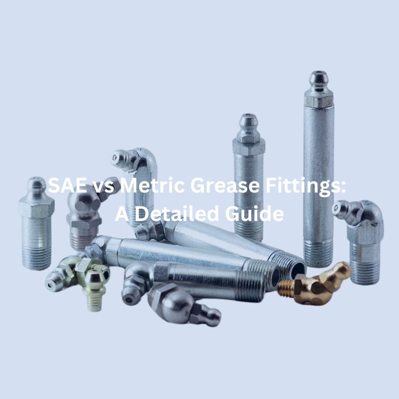
SAE vs Metric Grease Fittings: A Detailed Guide

Introduction

Grease fittings are small components that play an important role in machinery maintenance by allowing easy and efficient application of lubricant to moving parts. Proper lubrication is critical to minimizing wear, preventing corrosion, and extending equipment life. This detailed guide is designed to give readers a comprehensive understanding of SAE and metric grease fittings, including their features, applications, compatibility and selection criteria, so they can make informed decisions about their maintenance practices.

Understanding Grease Fittings

Grease fittings, also known as grease nipples or zerks, are mechanical components designed to facilitate the application of lubricants to moving parts of machinery. These fittings serve as access points through which grease can be injected directly into bearings, joints, and other components, ensuring that they remain well-lubricated and function smoothly. The primary function of grease fittings is to provide a sealed and secure pathway for lubricant delivery, preventing contaminants from entering the system and ensuring that lubrication reaches the intended areas effectively.

There are several types of grease fittings, each suited to different applications and environments. The most common types include:

  • Standard Grease Fittings: These are the most widely used and come in various thread sizes to fit different machinery. They feature a ball check mechanism that prevents dirt and debris from entering the fitting.
  • Flush Grease Fittings: These are designed to be flush with the surface of the machinery, making them less prone to damage in environments where protruding fittings might be knocked off or damaged.
  • Button Head Grease Fittings: Characterized by their larger diameter heads, these fittings are used in heavy-duty applications where a large volume of grease is required. They are particularly useful in industrial and construction equipment.

Proper lubrication is paramount in machinery maintenance, as it significantly reduces friction and wear between moving parts. Without adequate lubrication, components can quickly degrade, leading to increased downtime, higher maintenance costs, and a shorter lifespan for the machinery. Grease fittings ensure that the lubricant is delivered precisely where it is needed, enhancing the performance and reliability of the equipment. Additionally, regular lubrication through grease fittings helps in preventing rust and corrosion, which can compromise the integrity of the machinery over time.

Overview of SAE Grease Fittings

SAE grease fittings are predominantly used in the automotive industry, given their origins. However, their use has expanded to various other sectors, including agriculture, construction, aerospace, and heavy machinery. These fittings are integral to the maintenance of equipment such as tractors, excavators, aircraft, and industrial machines. The standardized nature of SAE fittings makes them highly versatile, suitable for a wide range of applications where reliable lubrication is critical.

Characteristics and Specifications of SAE Grease Fittings

SAE grease fittings are known for their precise engineering and durability. Key characteristics and specifications include:

  • Thread Sizes: SAE grease fittings come in a variety of thread sizes to accommodate different equipment requirements. Common thread sizes include 1/4″-28, 1/8″-27, 5/16″-18, and 3/8″-24, among others. These sizes correspond to specific applications and ensure a secure fit within the designated lubrication points.
  • Pressure Ratings: SAE grease fittings are designed to withstand varying pressure levels, ensuring that they can handle the demands of different lubrication systems. Typical pressure ratings for these fittings range from 6,000 to 10,000 psi, depending on the specific type and application. This ensures that the fittings can deliver lubricant effectively without leaking or failing under high pressure.
  • Materials Used: SAE grease fittings are typically made from durable materials such as steel, stainless steel, and brass. Steel fittings are commonly used due to their strength and cost-effectiveness. Stainless steel fittings offer superior corrosion resistance, making them suitable for harsh environments.

Overview of Metric Grease Fittings

Metric grease fittings are widely used in industries and regions that have adopted the metric system, including Europe, Asia, and many parts of Africa and Latin America. Common applications include automotive manufacturing, heavy machinery, industrial equipment, and agricultural machinery. Metric fittings are essential in maintaining equipment such as cars, trucks, construction vehicles, and farm equipment. Their use in these industries ensures that machinery remains well-lubricated and operates efficiently, reducing downtime and maintenance costs.

Characteristics and Specifications of Metric Grease Fittings

Metric grease fittings are designed to meet specific engineering standards, ensuring they provide reliable and efficient lubrication. Key characteristics and specifications include:

  • Thread Sizes: Metric grease fittings come in a range of thread sizes to suit different machinery and applications. Common thread sizes include M6x1, M8x1, M10x1, and M12x1. These sizes denote the diameter and pitch of the threads, allowing for precise fitting and secure attachment within lubrication points.
  • Pressure Ratings: Metric grease fittings are built to withstand high-pressure environments, ensuring they can deliver lubricant effectively without leakage or failure. Typical pressure ratings for these fittings range from 6,000 to 10,000 psi, similar to SAE fittings. This ensures they can handle the demands of various lubrication systems and maintain consistent performance under pressure.
  • Materials Used: The materials used in the construction of metric grease fittings are chosen for their durability and resistance to wear and corrosion. Common materials include steel, stainless steel, and brass. Steel fittings are favored for their strength and affordability, making them suitable for general applications. Stainless steel fittings offer excellent corrosion resistance and are ideal for use in harsh or corrosive environments. Brass fittings are also used for their corrosion resistance and ease of machining, often found in specialized applications where precision is critical.

Key Differences Between SAE and Metric Grease Fittings

Measure Metric Grease Fitting drawing

Thread Types and Sizes Comparison

One of the most notable differences between SAE and Metric grease fittings lies in their thread types and sizes. SAE (Society of Automotive Engineers) grease fittings typically use imperial thread sizes, such as 1/4″-28, 1/8″-27, 5/16″-18, and 3/8″-24. These threads are specified in inches and follow the Unified Thread Standard (UTS).

On the other hand, Metric grease fittings use thread sizes measured in millimeters, such as M6x1, M8x1, M10x1, and M12x1. The “M” denotes that the threads are metric, and the numbers indicate the diameter and pitch of the threads. The pitch refers to the distance between threads, which is crucial for ensuring a proper fit.

This difference in thread types means that SAE and Metric grease fittings are not directly interchangeable. Using the wrong type of thread can result in poor fitment, potential leakage, and damage to the machinery.

Dimensional Differences and Tolerances

SAE and Metric grease fittings also differ in their dimensional standards and tolerances. SAE fittings follow the UTS dimensional standards, which have specific guidelines for thread depth, diameter, and pitch. These standards ensure consistency and compatibility among various SAE fittings.

Metric grease fittings adhere to the International Organization for Standardization (ISO) standards, which dictate the dimensions and tolerances for metric threads. ISO standards ensure that Metric fittings maintain consistent thread dimensions and pitches, facilitating their use in metric-based systems.

Dimensional differences and tolerances between SAE and Metric fittings can affect the ease of installation and the reliability of the seal. Properly adhering to these standards is essential to ensure that the fittings perform optimally and do not cause mechanical issues.

Pressure Ratings and Performance Differences

While both SAE and Metric grease fittings are designed to handle high pressures, there can be differences in their performance based on their construction and application. Typical pressure ratings for both types of fittings range from 6,000 to 10,000 psi. However, specific applications might require fittings that can handle higher or lower pressures.

SAE fittings are often used in applications with rigorous performance requirements, such as automotive and aerospace industries. Their pressure ratings and performance are standardized to meet the stringent demands of these sectors.

Metric fittings, while also capable of handling high pressures, are commonly used in industrial and machinery applications. Their performance standards are set to meet the needs of these environments, ensuring reliable lubrication under various conditions.

Selection Criteria

Choosing the right grease fittings for your machinery is crucial for ensuring efficient lubrication and long-term reliability. When selecting between SAE and Metric grease fittings, several factors should be considered to ensure compatibility, performance, and ease of maintenance.

BSP grease fittings wholesale

Performance Requirements

  • Load and Pressure: Assess the operational load and pressure requirements of your machinery. High-load and high-pressure applications may require fittings with specific pressure ratings. Ensure that the selected grease fittings can handle the maximum pressure without risk of leakage or failure.
  • Lubricant Delivery: Consider the type and viscosity of the lubricant used. Some fittings are designed to accommodate thicker greases, while others are optimized for lighter oils. The fitting should ensure consistent and effective lubricant delivery to the critical parts of the machinery.
  • Frequency of Lubrication: Determine how often the machinery requires lubrication. Frequent lubrication needs might necessitate fittings that are easy to access and use, while less frequent needs might allow for more secure, less accessible fittings.

Environmental Factors

  • Operating Environment: Evaluate the conditions in which the machinery operates. In harsh environments with exposure to dirt, dust, moisture, or chemicals, corrosion-resistant materials like stainless steel or brass may be necessary to ensure longevity and reliability.
  • Temperature Extremes: Consider the temperature range within which the machinery operates. Extreme temperatures can affect the performance and durability of grease fittings. Materials and designs that can withstand high or low temperatures without degradation are preferable.
  • Exposure to Contaminants: Machinery exposed to contaminants requires grease fittings with effective sealing mechanisms to prevent dirt and debris from entering the lubrication system. This ensures the lubricant remains clean and effective.

Maintenance Considerations

  • Ease of Installation and Removal: Choose grease fittings that are easy to install and remove. This is particularly important for machinery that requires frequent maintenance. Quick and straightforward installation helps reduce downtime and maintenance costs.
  • Compatibility with Existing Equipment: Ensure that the new grease fittings are compatible with the existing equipment. This includes matching thread sizes, types, and material compatibility. Using fittings that align with current standards and specifications prevents potential issues during maintenance.
  • Availability and Replacement: Consider the availability of the grease fittings in your region. Easily accessible fittings reduce downtime when replacements are needed. Standardized fittings (either SAE or Metric) that are widely available can be advantageous.
  • Durability and Longevity: Select fittings made from high-quality materials that offer durability and long service life. This minimizes the need for frequent replacements and ensures continuous, reliable lubrication.

Selecting the right grease fittings involves a comprehensive evaluation of performance requirements, environmental factors, and maintenance considerations. By understanding the specific needs of your machinery and the conditions it operates in, you can choose grease fittings that enhance lubrication efficiency, reduce maintenance efforts, and extend the lifespan of your equipment. Whether opting for SAE or Metric fittings, ensuring compatibility and reliability is key to achieving optimal machinery performance and operational efficiency.

Installation and Maintenance Tips

  • Preparation: Before installation, ensure that the fitting and the receiving hole are clean and free from debris or old grease. Use a clean cloth or brush to remove any contaminants.
  • Thread Sealing: Apply a suitable thread sealant or Teflon tape to the threads of the grease fitting to prevent leaks and ensure a secure fit. This is especially important in high-pressure applications.
  • Insertion: Carefully screw the grease fitting into the receiving hole by hand to avoid cross-threading. Once it is hand-tight, use a wrench or a special grease fitting installation tool to secure it firmly in place. Avoid over-tightening, which can damage the threads and the fitting.
  • Alignment: Ensure the grease fitting is aligned correctly to allow easy access for the grease gun. Misalignment can make future lubrication difficult and may cause damage during maintenance.

Common Installation Mistakes and How to Avoid Them

  • Cross-Threading: One of the most common mistakes is cross-threading the fitting during installation. To avoid this, always start threading the fitting by hand and ensure it is properly aligned before using a wrench.
  • Over-Tightening: Over-tightening can strip the threads or damage the fitting. Tighten the fitting until it is snug and then apply a slight additional turn for security. Do not force it beyond this point.
  • Inadequate Sealing: Failing to use a thread sealant can lead to leaks. Always apply a suitable sealant to the threads before installation.

Troubleshooting Common Problems

  • Grease Leakage: If grease is leaking around the fitting, check for proper installation and ensure that the threads are sealed correctly. Replace damaged or worn fittings.
  • Blocked Fittings: If no grease is coming out when you apply the grease gun, the fitting may be blocked. Remove the fitting and clean it or replace it if necessary. Check the passage in the machinery for blockages as well.
  • Fitting Damage: If the fitting is damaged, bent, or worn, replace it immediately. Operating with a damaged fitting can lead to insufficient lubrication and potential machinery failure.
  • Difficulty in Lubrication: If it is hard to attach the grease gun or apply grease, ensure that the fitting is the correct type and size for your equipment. Also, check that the grease gun is functioning properly and filled with the correct lubricant.

Conclusion

In this detailed guide, we have explored the differences between SAE and metric grease fittings. By thoroughly evaluating these needs and understanding the unique benefits of each standard, you can make an informed decision that ensures optimal lubrication, performance, and service life for your equipment.

FAQ

SAE grease fittings use imperial thread sizes and are commonly used in the US, while Metric grease fittings use metric thread sizes and are prevalent in Europe and Asia.

No, SAE and Metric grease fittings are not interchangeable due to differences in thread types and sizes.

Common materials for grease fittings include steel, stainless steel, and brass, chosen for their durability and corrosion resistance.

To prevent cross-threading, always start threading the fitting by hand, ensuring it is properly aligned before using a wrench to secure it.

Thread sealant prevents leaks and ensures a secure fit, especially important in high-pressure applications.

Regularly inspect grease fittings for wear, damage, and blockages. Follow the manufacturer’s recommended lubrication schedule and keep fittings clean to ensure optimal performance.

More Posts

SAE Thread Fitting Types What You Need to Know

SAE Thread Fitting Types: What You Need to Know

SAE Thread Fitting Types: What You Need to Know

Table of Contents

Introduction

SAE fittings play a pivotal role in a myriad of industrial applications, beyond just automobiles and heavy machinery. These fittings are standardized under SAE guidelines, which ensures that they meet rigorous quality and safety standards crucial for applications in aerospace, agriculture, and construction equipment. This standardization helps manufacturers and maintenance teams streamline compatibility and inventory management, greatly reducing the risk of mismatches and equipment downtime.

Understanding SAE Threads

Basics of Thread Fitting

In mechanical engineering, threads are vital for assembling and disassembling components without causing damage or requiring permanent alterations. These helical structures facilitate the conversion of rotational movement into linear force, a principle central to many mechanical systems such as screws, bolts, and hydraulic fittings. Threads enable a tight fit between parts, which is crucial for maintaining pressure and preventing leaks in systems subjected to high dynamic loads. Their design allows for easy maintenance and repair by enabling components to be connected securely and removed as needed, which is particularly valuable in industrial applications where regular adjustments and inspections are necessary.

Introduction to SAE Fittings

SAE threads, established by the Society of Automotive Engineers, are designed to meet the stringent requirements of hydraulic systems, which demand robust sealing capabilities and enduring strength. These threads are characterized by their distinctive profile shapes that maximize sealing efficiency and mechanical fit. They are available in a variety of inch-based sizes and thread-per-inch configurations, providing a wide range of options to achieve the best fit for any given application. This standardization of thread profiles ensures that components are interchangeable and meet universal performance expectations, facilitating their use across a broad spectrum of industries and applications. The design and rigorous testing standards associated with SAE threads ensure they can withstand the pressures and challenges typical of modern hydraulic systems, thus guaranteeing reliability and safety in operation.

Types of SAE Fittings

SAE (Society of Automotive Engineers) hydraulic fittings are essential components in various hydraulic systems, designed to ensure tight and leak-free connections. Here’s a list of some common types of SAE hydraulic fittings, each serving specific applications and operational requirements:

SAE J514 37-Degree Flare (JIC) Fittings

The SAE J514 37-degree flare fittings, commonly referred to as JIC fittings, are renowned for their robust design which includes a flared tube end that provides a strong, durable metal-to-metal seal. This type of fitting is exceptionally versatile, and suitable for use in agricultural equipment, construction machinery, and aerospace applications. Their ability to handle medium to high-pressure conditions makes them ideal for hydraulic fluid conveyance in environments where shock and vibration are prevalent.

SAE O-Ring Boss Fittings

SAE ORB adapters supplier in China

SAE ORB fittings are designed with a male thread and an O-ring seated in a groove on the male face, offering a superior seal through the O-ring. This setup is particularly effective in high-pressure applications, ranging from hydraulic lifts to industrial presses, where the prevention of leaks is paramount. The simplicity of the seal structure allows for easier assembly and maintenance, enhancing their popularity in both static and dynamic hydraulic systems.

SAE O-Ring Face Seal Fittings

The ORFS fittings provide excellent leak protection with a zero-clearance design. The flat face and O-ring groove ensure a tight seal, reducing the potential for leaks, which is critical in systems exposed to high vibrations, such as mobile hydraulics and marine steering systems. The ORFS fittings’ robust design makes them suitable for high-pressure applications where hydraulic shock and fluctuations are common, ensuring a reliable and maintenance-free operation.

SAE Flange Fittings

SAE Flange fittings come in two main types: split (which includes two separate pieces that enclose the flange) and monoblock (where the flange is integrated as a single piece). These fittings are used extensively in heavy-duty applications, such as in commercial vehicles, large construction equipment, and industrial machinery, where large-diameter pipes or high-pressure flows are common. Their high strength and durability provide a secure and stable connection capable of withstanding extreme pressure and mechanical stress.

SAE 45-Degree Flare Fittings

This type of fitting, featuring a 45-degree flare angle, is generally used in lower-pressure environments compared to its 37-degree counterpart. Its applications include fuel and oil lines in automotive and aerospace industries, where a tight seal is necessary but the system pressure is relatively lower. The 45-degree flare fitting is particularly favored for its ease of assembly and effectiveness in systems where space and accessibility are limited.

SAE Inverted Flare Fittings

inverted flare Field attachable fitting Topa

Typically found in automotive applications, especially in brake and fuel systems, SAE inverted flare fittings are designed to provide reliable, leak-free connections in systems that require a metal-to-metal seal. The tube is flared outward and the fitting’s body provides the mating surface to form the seal. This design is highly effective for handling the high pressures seen in brake lines, ensuring safety and reliability in critical vehicle systems.

Each of these SAE hydraulic fitting types is crafted to meet specific technical standards and to perform reliably under varying conditions, making them indispensable in the realm of hydraulic systems design and maintenance.

Specifications and Standards

Technical Specifications

The technical specifications of SAE straight thread fittings are designed to meet rigorous industry requirements, ensuring performance under high pressure and adverse conditions. For instance, a common specification such as the 1/2-20 UNF thread size, featuring 20 threads per inch, is meticulously designed to ensure robust engagement and sealing capabilities. These specifications not only indicate the diameter and pitch of the thread but also define the type of seal required and the pressure rating. For hydraulic systems, these dimensions are critical as they must match precisely to prevent leaks and ensure system integrity. Materials used in these fittings are typically high-strength steel or stainless steel, chosen for their durability and resistance to corrosion and wear.

Standard Compliance and Certification

Adherence to established standards like SAE J514, which covers hydraulic tube fittings, is crucial for maintaining safety and efficiency across the industry. These standards are comprehensive, detailing not only the physical dimensions and tolerances but also the material specifications and assembly requirements. Compliance with such standards ensures that fittings from different manufacturers are interchangeable and can operate reliably in a unified system. Certification processes involve rigorous testing for durability, pressure resistance, and environmental resilience, guaranteeing that the fittings perform well under specified conditions.

Importance of Standardization in Hydraulic Systems

Standardization in hydraulic fittings, as enforced by standards like SAE J514, facilitates several critical benefits:

Interoperability: Ensures that components from different manufacturers can be used together without compatibility issues.

Safety: Reduces the risk of failures and leaks, which can lead to operational hazards and environmental damage.

Quality Assurance: Provides a benchmark for quality, helping consumers select products that meet industry-recognized criteria.

Innovation: Encourages manufacturers to innovate within the parameters of the standards, leading to improvements in efficiency and performance.

Industry Adoption and Regulatory Impact

The widespread adoption of SAE standards in the hydraulic fittings industry not only simplifies the design and maintenance of hydraulic systems but also influences regulatory practices. Regulatory bodies often incorporate these standards into safety and environmental regulations, which helps to streamline compliance efforts for manufacturers and users alike. The alignment of industry standards with regulatory requirements ensures that hydraulic systems are not only efficient and interchangeable but also compliant with international safety and environmental standards.

By adhering to precise technical specifications and robust standard compliance, the hydraulic fittings industry can maintain high levels of safety, reliability, and performance, ultimately contributing to the overall efficiency and sustainability of hydraulic systems across various applications.

Choosing the Right SAE Thread Fitting

Selecting the appropriate SAE hydraulic fitting is a meticulous process that demands consideration of several critical factors. These factors are designed to ensure optimal performance and longevity in hydraulic systems, where the right fitting can mean the difference between efficient operation and costly downtime.

Material Compatibility

material Topa China factory

Key Consideration: The compatibility of the fitting material with the hydraulic fluid is vital to prevent adverse chemical reactions that can degrade the material of the fitting, leading to leaks and potential system failure.

Common Materials:

Stainless Steel: Offers excellent corrosion resistance and strength, making it suitable for a wide range of hydraulic fluids and environments.

Carbon Steel: Generally less expensive than stainless steel and effective in non-corrosive environments. It’s commonly used where little to no moisture is present.

Brass: Best suited for applications involving water-based fluids and gases, brass fittings are resistant to corrosion from water but may not be suitable for stronger acids or alkalis.

Pressure Ratings

Importance: Ensuring the fitting can handle the system’s maximum pressure is critical to prevent blowouts and failures. The fitting must sustain not just the average working pressure but also any spikes or surges.

Assessment:

Verify Ratings: Check the pressure ratings of the fittings, often measured in psi (pounds per square inch). Ensure that the fitting’s rating exceeds the maximum expected system pressure by a safe margin.

Factor in Safety Margins: Engineering standards often recommend a safety factor, usually about 1.5 to 4 times the maximum operating pressure, depending on the application’s criticality and variability.

Environmental Factors

Temperature:

Range Consideration: The temperature range within which the system operates must be within the tolerable range of the fitting material. Extreme temperatures can affect the resilience and sealing capability of the material.

Thermal Expansion: Materials expand and contract with temperature changes. This dimensional change can affect the tightness and efficacy of the seal.

Corrosion Potential:

Environmental Exposure: Fittings exposed to corrosive environments, such as marine settings or areas with chemical exposure, require materials like high-grade stainless steel or specially coated metals.

Protective Measures: In highly corrosive environments, consider additional protective measures such as coatings, anodic protection, or using more inert materials to prolong the life of the fittings.

When choosing SAE fittings, it’s not just about selecting the right type but also about ensuring that every aspect of the fitting is tailored to the operational demands and environmental conditions of the system. Detailed knowledge of material properties, pressure requirements, and environmental factors is crucial for making informed decisions.

Troubleshooting Common Issues

Maintaining the integrity and performance of SAE thread fittings is vital to ensure the long-term reliability of hydraulic systems. Below are expanded insights into common issues and their comprehensive troubleshooting methods:

Incorrect Thread Engagement

Problem Description: Incorrect thread engagement often leads to several issues like leaks, which can compromise the hydraulic system’s efficiency, or thread stripping, which severely undermines the fitting’s structural integrity.

Solutions:

Proper Installation Practices: Always start by hand-threading to ensure that the threads are correctly aligned. This reduces the risk of cross-threading.

Use of Thread Lockers and Sealants: In applications where vibrations or varying pressures might loosen the fittings, apply thread lockers or appropriate sealants. This helps in creating a more secure and leak-proof seal.

Regular Inspections

Preventive Measures:

Scheduled Maintenance: Implement a routine inspection schedule to monitor the condition of fittings. This can be aligned with regular maintenance checks of the hydraulic system.

Checklist Development: Develop a detailed checklist that includes looking for signs of wear, corrosion, evident leaks, or any damage to the thread fittings.

Tool Usage:

Correct Tools Selection: Use the right tools for installation and maintenance to avoid damaging the fittings. For instance, using a wrench that fits the fittings properly can prevent slippage and potential rounding off of the edges.

Adherence to Torque Specifications

Critical Aspect: Incorrect torque application can either lead to loose fittings, resulting in leaks, or over-tightened fittings, which may cause damage to both threads and the fittings’ body.

Implementation Strategies:

Use of Torque Wrenches: Always use a calibrated torque wrench when installing fittings to apply the exact required torque. This precision tool helps prevent under-tightening or over-tightening.

Advanced Diagnostics and Monitoring

Technological Integration: Incorporate condition monitoring tools and systems that can detect early signs of leaks or failure. For instance, sensors can be installed to monitor system pressure and detect fluctuations that might indicate a fitting problem.

Data Analysis: Regular analysis of operational data can help predict potential issues before they become critical. This proactive approach allows maintenance teams to address problems promptly, reducing downtime and maintenance costs.

By thoroughly understanding these common issues and implementing robust troubleshooting strategies, maintenance teams can significantly enhance the reliability and performance of hydraulic systems using SAE fittings.

Conclusion

SAE threaded fittings are an integral part of hydraulic systems, providing reliability and safety through standardized design. Understanding their types, specifications and proper selection criteria is critical to optimizing system performance. As the industry evolves, it is critical to stay up-to-date on the latest advances in technology and standards. Working with professional groups and standards bodies can provide opportunities for continuous learning and adaptation. Contact Topa for our comprehensive guide to SAE threaded fittings for more in-depth information.

FAQ

SAE fittings are primarily used in hydraulic systems to ensure secure, leak-proof connections. They are widely utilized in industries such as automotive, aerospace, and heavy machinery, where reliable hydraulic connections are crucial.

Choosing the right hydraulic SAE fitting involves considering several factors such as material compatibility with the hydraulic fluid, pressure ratings that exceed the maximum pressure of the system, and environmental factors like temperature and corrosion potential. Always consult with a specialist or refer to manufacturer specifications for precise selection.

SAE straight threads rely on an O-ring or a backup washer to create a seal, making them suitable for high-pressure applications. SAE tapered threads, on the other hand, form a seal by the wedging action of the threads themselves, ideal for applications where the fitting needs to be frequently reassembled.

SAE standard fittings, particularly those designed with straight threads and O-rings, can often be reused if they are not damaged and the O-ring is still in good condition. However, fittings that show any signs of wear, damage, or deformation should be replaced to ensure system integrity.

Proper installation of an SAE fitting requires ensuring the threads are clean and free of debris, aligning the threads correctly to avoid cross-threading, and tightening the fitting to the manufacturer’s specified torque. Using a torque wrench is recommended to achieve the correct tightness.

Regular inspections for signs of wear, leaks, or corrosion are essential. It’s also important to ensure all fittings are tightened to the correct specifications, especially after system pressure changes or maintenance. Replace seals and O-rings as necessary to maintain a leak-free system.

More Posts

How to Measure SAE Fitting

How to Measure SAE Fitting

How to Measure SAE Fitting: Step-by-Step Guide

Introduction

There are several types of SAE fittings, including SAE J512, which is commonly used in automotive and refrigeration systems, and SAE J514, which is commonly used in hydraulics. each type has specific characteristics and applications. The purpose of this guide is to provide a comprehensive, step-by-step approach to accurately measuring SAE fittings. Accurate measurements are critical to ensure proper fitting selection, compatibility, and system integrity, ultimately improving the efficiency and longevity of your hydraulic system.

Understanding SAE Fittings

Definition and Characteristics of SAE Fittings

SAE fittings are standardized connectors established by the Society of Automotive Engineers. SAE fittings are characterized by their precision engineering, which allows them to maintain high performance under varying pressures and temperatures. They are made from robust materials like stainless steel, carbon steel, and brass, which provide durability and resistance to corrosion. The key characteristics of SAE fittings include their specific thread types, sealing methods, and dimensional standards, which ensure compatibility and interchangeability across different hydraulic systems and components.

SAE J512

SAE J512 fittings are widely used in the automotive and refrigeration industries. These fittings are designed for low and medium-pressure applications and are available in flared and inverted flared connection designs. In automotive systems, SAE J512 fittings are used in fuel lines, brake lines, and drivelines to provide secure, leak-proof connections. In refrigeration systems, these fittings are essential for connecting various components such as compressors, evaporators, and condensers to ensure efficient and reliable operation.

SAE J514

SAE J514 fittings are primarily used in hydraulic systems because of their ability to withstand high-pressure environments. These fittings include a variety of connection types, such as straight thread, tapered thread, and four-bolt flange connections. sae j514 fittings are critical in heavy machinery, industrial equipment, and mobile hydraulic applications to ensure the safe and efficient delivery of hydraulic fluid. The design of these fittings includes metal-to-metal or elastomeric seals that provide a reliable barrier against leakage. SAE J514 fittings are ruggedly constructed and precision threaded for demanding hydraulic applications to ensure system life and performance.

SAE J1453

SAE J1453, commonly known as O-Ring Face Seal (ORFS) fittings, are designed for high-pressure hydraulic applications where leak prevention is critical. ORFS fittings feature a flat face and an O-ring seal, which provides a superior seal compared to traditional metal-to-metal contact. This design significantly reduces the risk of leaks, even under high-pressure conditions, making ORFS fittings ideal for use in hydraulic systems exposed to extreme pressures and vibrations. Applications for SAE J1453 fittings include heavy construction equipment, agricultural machinery, and industrial hydraulic systems. The O-ring seal ensures a tight connection, minimizing downtime and maintenance costs associated with hydraulic fluid leaks.

Differences Between SAE Fittings and Other Standard Fittings

JIC vs SAE

NPT Hydraulic Fittings

NPT fittings, standardized under ANSI/ASME B1.20.1, utilize tapered threads to create a seal as they are screwed together, often requiring thread sealant to enhance the seal. Commonly used in plumbing, gas lines, and low-pressure fluid transfer applications, NPT fittings are known for their simple design and ease of use in low to medium-pressure environments. Unlike SAE fittings, which use straight threads and various sealing mechanisms like O-rings, NPT fittings rely on thread interference for sealing, making them distinct in design and function.

BSP Fittings

BSP fittings, standardized under BS 21 and ISO 228, come in two thread types: BSPT (tapered) and BSPP (parallel). These fittings are commonly used in plumbing and hydraulic systems, particularly in Europe and other regions. BSPT fittings create a seal using thread taper, while BSPP fittings require a washer or O-ring for sealing. With a 55° thread angle, BSP threads differ from SAE threads, which have a 60° angle. Additionally, BSP threads include both tapered (BSPT) and parallel (BSPP) designs, whereas SAE fittings typically use straight threads. BSP fittings are widely used internationally and are versatile for various applications.

Metric Fittings

Metric fittings, standardized under ISO 261 and ISO 262, use metric threads (M) measured in millimeters for pitch and diameter. Commonly applied in international hydraulic systems, automotive, and machinery, these fittings often utilize O-rings or bonded seals for sealing. The metric system’s ease of integration and international standardization offer significant advantages. Unlike SAE fittings, which use inches for thread measurement, metric fittings rely on millimeters. Additionally, while metric fittings share some sealing methods with SAE fittings, such as O-rings, they differ from NPT and BSPT fittings, which use thread interference for sealing.

Feature

SAE

JIC

NPT

BSP

Metric

Thread Type

UN/UNF

UN/UNF

Tapered
(NPT)

Tapered(BSPT),
Parallel (BSPP)

Metric(M)

Common
Applications

Automotive,
hydraulic
Systems,
refrigeration,
aerospace

Hydraulic
systems,
fuel
delivery
fluid power

Plumbing,
gas  lines,
low-
pressure
fluid
transfer

Plumbing,
hydraulic
systems in
Europe

International
hydraulic
systems,
automotive,
machinery

Sealing
Method

Metal-to-
metal,O-rings

37°flare
metal-to-
metal

Tapered
threads
with sealant

Tapered
threads,
washers,O-
rings

O-rings,
bonded seals

Thread
Angle

60°

37°flare

60°

55°

Varies

Advantages

High reliability,
precision,
vibration
resistance

High

pressure
and
vibration
resistance

Simple,
easy to use

Widely used
internationally,
versatile

International
standard,easy
integration

Step-by-Step Guide

Outer Diameter of the Fitting

Tools Needed:

Calipers (digital or vernier)

Clean cloth or brush

Steps:

Clean the Fitting: Before measuring, ensure that the fitting is clean and free from any debris or corrosion. Use a clean cloth or brush to remove any dirt or residues that might affect the measurement.

Zero the Calipers: If using digital calipers, ensure they are zeroed before measuring. For vernier calipers, ensure they are correctly set to zero.

Position the Calipers: Open the calipers and place them around the outermost part of the fitting’s diameter. Ensure the calipers are perpendicular to the fitting to avoid angled measurements, which can result in inaccuracies.

Measure the Diameter: Gently close the calipers until they touch the fitting’s surface without compressing it. Read the measurement displayed on the digital calipers or from the vernier scale. Record the outer diameter.

Verify the Measurement: Repeat the measurement process a few times to ensure consistency. If the measurements vary, average them to get a reliable diameter.

hydraulic fittings measure tools Topa

Length of the Fitting

Tools Needed:

Measuring tape or ruler

Calipers (for smaller fittings)

Steps:

Prepare the Fitting: As with the diameter measurement, ensure the fitting is clean and free from debris.

Select the Measuring Tool: Use a measuring tape for larger fittings or calipers for smaller fittings.

Measure the Length: Place the measuring tool along the length of the fitting, starting from one end to the other. Ensure the measuring tape or ruler is straight and not bent, as this can lead to inaccuracies.

Record the Measurement: Note the length indicated on the measuring tool. For smaller fittings, use calipers for a more precise measurement by placing the jaws at the two ends of the fitting.

Repeat for Accuracy: Measure the length multiple times to ensure accuracy and record the most consistent measurement.

Flare Angle Measurement (If Applicable)

Tools Needed:

Flare gauge or protractor

Calipers (for measuring reference points)

Steps:

Identify the Flare Angle: Determine if the fitting has a flare angle. Common flare angles are 37° (AN/JIC fittings) and 45° (SAE fittings).

Use a Flare Gauge: Place the flare gauge against the fitting’s flare to check the angle. Ensure the gauge is properly aligned with the flare surface.

Measure with a Protractor: If a flare gauge is not available, use a protractor. Place the fitting on a flat surface and align the protractor’s center with the fitting’s center. Measure the angle by aligning the protractor’s baseline with the fitting’s flare surface.

Record the Angle: Note the flare angle measured. Verify the angle by measuring at different points around the flare to ensure uniformity.

Confirm Accuracy: Double-check the flare angle by comparing it with standard flare angles for SAE fittings to confirm it matches the expected angle.

Examine the Threads

Once cleaned, closely examine the threads to identify the type of thread. SAE fittings typically use UN (Unified National) or UNF (Unified National Fine) threads. The type of thread can often be determined by the appearance and feel of the threads, but for precise identification, you may refer to thread charts or standards.

Unified National Fine (UNF)

UNF threads have a finer pitch, meaning the threads are closer together compared to UNC threads. This results in more threads per inch (TPI). UNF threads are available across a range of diameters, typically from small to medium sizes. The finer threads provide a greater surface area in contact with the mating part, which can offer a stronger and more secure hold.

Unified National Coarse (UNC)

UNC threads have a coarser pitch, meaning the threads are spaced further apart compared to UNF threads. This results in fewer threads per inch (TPI). UNC threads are also available in a wide range of diameters, typically from small to large sizes. The coarser threads make UNC fasteners easier to assemble and disassemble, even in less-than-ideal conditions.

Thread Pitch Measurement

Select the Thread Gauge

Thread pitch gauges come with multiple blades, each marked with different pitch values. Select a thread pitch gauge that corresponds to the type of threads you are measuring (UN or UNF). Ensure that the gauge covers the range of thread pitches you might encounter in SAE fittings.

Match the Threads

Take the thread pitch gauge and place one of its blades against the threads of the fitting. Ensure that the blade is aligned with the threads, making full contact along the entire length of the threads.

Slide the blade gently along the threads to see if it matches perfectly. If it does not, try the next blade on the gauge until you find one that fits precisely. The correct blade will nestle perfectly into the threads without any gaps or rocking.

Confirm the Match: A perfect match means that the blade’s teeth align exactly with the thread grooves on the fitting. The gauge should fit snugly into the threads without forcing it.

Read the Pitch

Once you find the blade that matches the threads, look at the markings on the thread pitch gauge. The blade will have a pitch value indicated, usually in threads per inch (TPI) for SAE threads.

Note the pitch value. This value represents the number of threads per inch and is critical for ensuring you have the correct thread specifications for replacement or compatibility checks.

Identifying Thread Types and Sizes

Accurately identifying thread types and sizes is essential for ensuring proper fit and function in hydraulic systems. SAE (Society of Automotive Engineers) fittings commonly use Unified National (UN) and Unified National Fine (UNF) thread types. This section explains these thread types and provides a detailed guide on how to identify thread type and size using thread gauges, understanding thread pitch, and determining thread diameter.

Troubleshooting Common Issues

Accurately measuring SAE fittings is crucial for ensuring the proper fit and function of hydraulic systems. However, several common problems can arise during the measurement process. This section highlights these issues and provides solutions and tips for troubleshooting them.

Incorrect Thread Identification

Issue:

Misidentifying thread type (e.g., UNC vs. UNF) can lead to selecting the wrong fitting, causing leaks or mechanical failures.

Solution:

Clean the Threads: Ensure threads are clean before measuring. Debris can obscure the thread profile.

Use Correct Gauges: Use thread pitch gauges specifically designed for SAE threads. Verify the pitch using multiple gauges if necessary.

Consult Standards: Cross-reference your measurements with standard thread charts to confirm the thread type.

Inaccurate Measurements Due to Tool Errors

Issue:

Calipers, micrometers, and thread gauges can give inaccurate readings if they are not calibrated or used correctly.

Solution:

Calibrate Regularly: Ensure all measurement tools are regularly calibrated according to manufacturer specifications.

Use Quality Tools: Invest in high-quality measuring tools to minimize errors. Cheap tools can be prone to inaccuracies and wear out quickly.

Check Tool Condition: Inspect tools for damage or wear before use. Damaged tools can give false readings.

Misinterpretation of Measurement Data

Issue:

Incorrectly interpreting measurement data can lead to choosing the wrong fitting size or type.

Solution:

Double-Check Readings: Always take multiple measurements and compare them. Averaging multiple readings can help eliminate errors.

Cross-Reference: Use reference materials such as thread size charts and fitting catalogs to verify measurements.

Conclusion

This guide has detailed the process of measuring SAE fittings, covering the identification of thread types and sizes, and the specific methods for measuring internal and external dimensions. Accurate measurement is crucial for maintaining the integrity and performance of hydraulic systems, preventing leaks, and ensuring reliable operation. By practicing and refining your measurement skills, you can ensure proper fitting selection and compatibility. We encourage you to share this guide, and provide feedback.

FAQ

You will need calipers, thread pitch gauges, a measuring tape, and possibly a protractor for measuring flare angles.

Use a clean cloth or brush to remove any dirt, grease, or debris from the fitting’s threads and surfaces.

UNF (Unified National Fine) threads have a finer pitch with more threads per inch, while UNC (Unified National Coarse) threads have a coarser pitch with fewer threads per inch.

Use a thread pitch gauge by matching the threads on the fitting with the corresponding gauge blade until you find a perfect fit.

Ensure your tools are calibrated, measure multiple times, and average the results. Clean the fitting and tools before measuring.

Accurate measurements ensure proper fitting selection, prevent leaks, and maintain the performance and safety of hydraulic systems.

More Posts

Compression vs Flare Fittings Which One Should You Choose

Compression vs Flare Fittings: Which One Should You Choose

Compression vs Flare Fittings: Which One Should You Choose?

Table of Contents

Introduction

Choosing the right fitting for your plumbing or industrial project can significantly impact the system’s performance and longevity. Did you know that improper fitting selection is a leading cause of system failures, costing industries millions in repairs and downtime each year? In this post, we will delve into a detailed comparison of compression and flare fittings. By examining their characteristics, advantages, and typical applications, we aim to provide you with the information needed to make an informed decision.

Understanding Compression Fittings

Definition and Overview

Compression fittings are widely used components in various fluid and gas transfer systems. They are designed to create a secure, leak-proof connection between two pipes or a pipe and a fixture. The primary components of a compression fitting include the compression nut, ferrule (also known as an olive), and the fitting body.

Compression Nut: This is a threaded nut that fits over the pipe and screws onto the fitting body, applying pressure to the ferrule.

Ferrule: A small ring made of metal or plastic that fits snugly around the pipe. When compressed by the nut, the ferrule forms a tight seal between the pipe and the fitting body.

Fitting Body: The main component that houses the ferrule and connects the two pipe ends. It often includes a seat or shoulder against which the ferrule is compressed.

How They Work

Compression fittings operate by using the compression force applied by the nut to create a seal. Here’s a step-by-step breakdown of how they work:

Preparation: The pipe end is cut cleanly and squarely, with any burrs removed to ensure a smooth fit.

Assembly: The compression nut and ferrule are placed onto the pipe.

Connection: The pipe is inserted into the fitting body until it sits against the fitting shoulder.

Compression: The compression nut is tightened onto the fitting body, which compresses the ferrule around the pipe. This action deforms the ferrule slightly, creating a tight seal between the pipe and the fitting body.

Types of Compression Fittings

Brass Compression Tube Fittings-Male Elbow

Compression fittings come in various types to suit different applications and preferences. Here are the most common types:

Double Ferrule Compression Fittings:

These fittings use two ferrules to create a stronger and more secure seal. The front ferrule provides the primary seal, while the back ferrule grips the pipe.

Standard Compression Fittings:

Standard compression fittings are the most common type, consisting of a compression nut, ferrule, and body. They are versatile and widely used for connecting pipes in various applications, providing a reliable seal when the nut is tightened.

Double Ferrule Compression Fittings:

Double ferrule compression fittings feature two ferrules instead of one. The front ferrule provides a seal while the back ferrule grips the pipe, offering enhanced reliability and resistance to vibration, making them suitable for high-pressure and high-vibration applications.

Flareless Compression Fittings:

Flareless compression fittings do not require flaring of the pipe ends. They use a single ferrule that compresses onto the pipe when the nut is tightened, providing a leak-proof connection without the need for pipe preparation.

Common Applications

Compression fittings are used in a variety of industries and applications due to their reliability and ease of use. Common applications include:

Residential Plumbing: Used for connecting water supply lines to faucets, toilets, and other fixtures.

HVAC Systems: Employed in heating and cooling systems to connect refrigerant lines.

Automotive: Used in fuel and hydraulic lines within vehicles.

Industrial: Applied in chemical processing, oil and gas, and other industrial systems requiring secure fluid connections.

Advantages

Compression fittings offer several benefits:

Ease of Installation: They can be installed without specialized tools, making them accessible for both professionals and DIY enthusiasts.

Reusability: Compression fittings can be disconnected and reconnected multiple times without significant loss of sealing capability.

Compatibility: They work well with a variety of materials, including copper, plastic, and steel pipes.

Disadvantages

Despite their advantages, compression fittings have some limitations:

Potential for Leaks: If not properly installed or if the pipe is not perfectly cut, leaks can occur. Ensuring a clean, square cut and proper tightening is crucial.

Pressure Limitations: Compression fittings are generally suitable for low to moderate-pressure applications. For high-pressure systems, alternative fittings might be necessary.

Understanding Flare Fittings

Definition and Overview

Flare fittings are a type of compression fitting used to connect metal tubing, providing a robust and leak-proof seal. They are commonly utilized in high-pressure applications due to their reliable and durable connections. The key components of a flare fitting include the flare nut, flare fitting, and the tube itself.

Flare Nut: This is a threaded nut that fits over the tube and screws onto the flare fitting, securing the connection.

Flare Fitting: The flare fitting, often called the flare body, has a conical seat that matches the flared end of the tube. This component provides the surface against which the tube is compressed.

Tube: The tube is typically made of metal (e.g., copper, aluminum, or stainless steel) and is flared at the end to match the conical seat of the flare fitting.

How They Work

Flare fittings create a seal through the compression of the flared end of the tube against the conical seat of the flare fitting. Here’s a step-by-step explanation of how they work:

Preparation: The end of the tube is cut squarely, deburred, and flared using a flaring tool to form a 45-degree or 37-degree angle.

Assembly: The flare nut is placed over the tube, followed by the insertion of the flared end into the flare fitting.

Compression: The flare nut is tightened onto the flare fitting, compressing the flared end of the tube against the conical seat of the fitting.

Sealing: The compression creates a tight seal between the flared tube and the fitting, ensuring a leak-proof connection.

Flare hydraulic fittings kits Topa

Common Applications

Flare fittings are widely used across various industries due to their reliability and ability to handle high-pressure environments. Common applications include:

Residential Plumbing: Used for gas lines and water supply connections.

HVAC Systems: Employed in refrigerant lines and air conditioning units.

Automotive: Used in brake lines, fuel lines, and hydraulic systems within vehicles.

Aerospace: Applied in hydraulic and fuel systems in aircraft.

Industrial: Utilized in high-pressure fluid and gas transfer systems in industrial settings.

Types of Flare Fittings

There are different types of flare fittings designed to meet various requirements and standards:

45-Degree Flare Fittings: These are the most common type, used primarily in residential plumbing and HVAC systems. The tube is flared to a 45-degree angle.

37-Degree Flare Fittings: Commonly used in high-pressure applications such as aerospace and hydraulic systems, these fittings offer a higher degree of sealing and reliability. The tube is flared to a 37-degree angle.

Inverted Flare Fittings: These fittings have an inverted cone design and are used in automotive brake and fuel systems, providing an extra layer of security against leaks.

Advantages

Flare fittings offer several notable advantages:

Strong, Leak-Proof Connections: The flared end of the tube forms a tight seal against the conical seat, preventing leaks.

Suitability for High-Pressure Applications: The robust design makes flare fittings ideal for use in high-pressure environments.

Durability: Flare fittings can withstand significant mechanical stress and vibrations, making them suitable for demanding applications.

Disadvantages

Despite their strengths, flare fittings do have some drawbacks:

Requires Special Tools for Installation: Installing flare fittings necessitates the use of a flaring tool, which can be a barrier for those without the proper equipment.

Not as Easy to Install or Adjust as Compression Fittings: The installation process for flare fittings is more involved and requires precision, making it less convenient than using compression fittings.

Detailed Comparison Between Flare and Compression Fittings

Definition and Components

Compression Fittings:

Definition: Compression fittings are used to join two pipes or a pipe to a fixture, creating a secure and leak-proof connection.

Components: Consists of a compression nut, ferrule (olive), and fitting body. The ferrule is compressed between the nut and the fitting body to create a seal.

Flare Fittings:

Definition: Flare fittings are designed to connect metal tubing by creating a secure, leak-proof seal through the flaring of the tube end.

Components: Include a flare nut, flared tube end, and flare fitting body with a conical seat that matches the flared tube.

Installation Process

Compression Fittings:

Procedure:

Cut the pipe squarely and clean the ends.

Slide the compression nut and ferrule onto the pipe.

Insert the pipe into the fitting body and tighten the nut to compress the ferrule and create a seal.

Flare Fittings:

Procedure:

Cut the pipe squarely and clean the ends.

Use a flaring tool to flare the end of the pipe to a 45-degree or 37-degree angle.

Place the flare nut over the flared pipe end and insert it into the flare fitting body.

Tighten the flare nut to compress the flared end against the fitting body’s conical seat.

Performance and Reliability

Compression Fittings:

Pressure Handling: Suitable for low to medium-pressure applications. Common in household plumbing and light industrial uses.

Mechanical Stress: Adequate for systems with minimal vibrations and mechanical stress.

Durability: May require periodic checks to ensure no leaks develop over time. Connections can loosen under vibration or thermal expansion.

Flare Fittings:

Pressure Handling: Designed for high-pressure environments. Common in HVAC refrigerant lines, gas lines, and automotive systems.

Mechanical Stress: Excellent for environments with significant mechanical stress and vibration. Common in automotive and aerospace systems.

Durability: Known for long-term durability and strong, leak-proof connections, especially in high-stress environments.

Compression seal Topa
Flare type seal Topa

How to Choose Between Compression and Flare Fittings

Key Factors to Consider

When deciding between compression and flare fittings, it’s essential to evaluate several key factors to ensure you choose the best option for your specific application. These factors include:

Pressure Requirements: Determine the pressure levels your system will encounter. Compression fittings are suitable for low to medium-pressure applications, while flare fittings are ideal for high-pressure environments.

Mechanical Stress: Assess the amount of mechanical stress and vibration your system will experience. Compression fittings are adequate for low-stress environments, whereas flare fittings excel in high-stress and high-vibration settings.

Ease of Installation: Consider the skill level required and the availability of tools. Compression fittings are easier to install and require basic tools, making them suitable for both DIY enthusiasts and professionals. Flare fittings, on the other hand, require more skill and specialized tools.

Material Compatibility: Check the compatibility of the fittings with the materials you are using. Compression fittings work well with various materials, including copper, plastic, and steel. Flare fittings are typically used with metal pipes like copper, aluminum, and stainless steel.

Maintenance Needs: Evaluate the ease of maintenance and reusability. Compression fittings are easier to adjust and maintain, while flare fittings offer long-term durability and are less prone to leaks in high-pressure applications.

Cost: Factor in the initial cost of the fittings and the tools required for installation, as well as potential maintenance costs.

Decision-Making Guide

Follow this step-by-step guide to determine whether compression or flare fittings are the right choice for your project:

Identify Application Requirements:

Pressure Levels: Assess the pressure requirements of your system.

Mechanical Stress: Consider the level of mechanical stress and vibration.

Material Compatibility: Ensure the fittings are compatible with the materials used in your system.

Evaluate Installation Needs:

Skill Level: Determine if the installation will be performed by a professional or a DIY enthusiast.

Tool Availability: Check if the necessary tools for installation are available.

Consider Maintenance and Durability:

Ease of Adjustment: Decide if the fittings need to be frequently adjusted or maintained.

Long-Term Durability: Assess the expected longevity and reliability of the fittings.

Calculate Costs:

Initial Cost: Compare the costs of the fittings and the required tools.

Maintenance Costs: Estimate the potential maintenance expenses over time.

Make an Informed Decision:

Based on the above factors, determine which type of fitting best meets your needs. If you require fittings for a high-pressure, high-stress environment and have the necessary skills and tools, flare fittings are the better choice. For lower pressure applications with minimal stress and easier installation, compression fittings are more suitable.

Conclusion

In conclusion, compression fittings are ideal for low to medium pressure applications, are easy to install, and are versatile, while flare fittings excel in high pressure and high pressure environments, providing a durable, leak-proof connection. We want to hear about your experiences with compression and flare fittings. If you need further assistance or advice, please feel free to contact us directly.

FAQ

What are compression fittings?

Compression fittings are used to connect pipes or a pipe to a fixture by compressing a ferrule between a nut and the fitting body to create a leak-proof seal.

What are flare fittings?

Flare fittings connect metal tubing by flaring the tube end and compressing it against a conical seat in the fitting body, creating a strong and leak-proof connection.

Which applications are best for compression fittings?

Compression fittings are best for low to medium-pressure applications such as household plumbing, HVAC systems, and light industrial uses.

When should I use flare fittings?

Flare fittings are ideal for high-pressure applications, including HVAC refrigerant lines, gas lines, automotive brake and fuel systems, and aerospace hydraulic systems.

What tools do I need for installing compression fittings?

Installing compression fittings requires basic tools like an adjustable wrench or spanner.

What tools do I need for installing flare fittings?

Installing flare fittings requires a flaring tool and a wrench, as the tube end needs to be precisely flared to fit the fitting body.

What is a Flare Fitting

What is a Flare Fitting

What is a Flare Fitting: The Final Guide

Introduction

Among the diverse types of fittings available, flare fittings distinguish themselves through their robust design and adaptable nature. Engineered to accommodate metal tubing such as copper or aluminum, flare fittings utilize a compression mechanism to create secure, leak-resistant connections. This makes them particularly suited for applications where reliability and ease of installation are paramount.

Understanding Flare Fittings

Definition and Purpose

Flare fittings, also referred to as flare nut fittings or flared fittings, represent a specialized category of compression fittings extensively used in plumbing, automotive, and industrial applications. These fittings excel in creating robust, leak-resistant connections for metal tubing, predominantly copper or aluminum, in environments where reliability and ease of assembly are paramount.

Applications in Various Industries

Flare fittings are indispensable in industries where the integrity of fluid and gas transfer systems is critical. They are particularly valued for their ability to maintain tight seals under high pressures, making them ideal for applications involving hydraulic systems, fuel lines, and HVAC (Heating, Ventilation, and Air Conditioning) components. Their versatility extends across residential, commercial, and industrial sectors, where they ensure efficient fluid and gas transmission without compromising safety or performance.

Components of a Flare Fitting

Fitting Body: Constructed from robust materials such as brass, stainless steel, or other corrosion-resistant alloys, the fitting body serves as the main housing for the tubing. It provides structural integrity and support while accommodating the tubing securely.

Nut: Positioned at the end of the fitting body, the nut plays a pivotal role in the assembly process. When tightened, it exerts pressure on the next crucial component—the sleeve or ferrule.

Sleeve or Ferrule: This critical component is instrumental in achieving a reliable seal. Usually made from soft metals like copper, aluminum, or even plastic, the sleeve slides over the end of the tubing. As the nut is tightened, the sleeve is compressed uniformly against the tubing and fitting body, forming a tight seal that prevents leaks even under demanding conditions.

Types of Flare Fittings

Flare hydraulic fittings kits Topa

Properly connecting brass pipe fittings involves several crucial steps to ensure a secure, leak-free joint. This step-by-step guide will help you navigate the process with precision and confidence.

Single Flare vs Double Flare

After cutting the pipe, you may notice rough edges or burrs at the cut ends. Use a deburring tool to remove these burrs, creating a smooth edge. This step is crucial as burrs can prevent the pipe from fitting properly into the fitting and can cause leaks. Once deburred, clean the pipe thoroughly to remove any debris, oils, or residues. Use a clean cloth or pipe cleaner to ensure the pipe is free of contaminants that could interfere with the seal.

Flare fittings are distinguished primarily by their configuration, with single flare and double flare being the two main types:

Single Flare:

Definition: Single flare involves the basic flaring of the tubing’s end. The tubing end is shaped outward to create a sealing surface against the fitting body when compressed.

Applications: Single flare fittings are commonly used in less demanding applications where moderate pressures are involved. They are simpler to create and are often found in household plumbing and low-pressure hydraulic systems.

Double Flare:

Definition: Double flare includes an additional step where the tubing end is flared twice. The first flare creates a seating surface, and the second flare folds the tubing edge back onto itself, forming a more secure and robust seal.

Applications: Double flare fittings are preferred in applications requiring higher pressure tolerance and enhanced resistance to vibration and mechanical stress. They are extensively used in automotive brake and fuel line systems, where safety and reliability are critical.

45-Degree Flare Fitting

Angle: The flare in a 45-degree flare fitting is formed at a 45-degree angle relative to the axis of the tubing.

Application: These fittings are commonly used in automotive brake systems and some refrigeration applications. They provide a secure seal and are compatible with soft metal tubing like copper.

37-Degree JIC Flare Fitting

Angle: The JIC flare fitting uses a 37-degree angle for the flare. This angle is standardized by the Joint Industry Council and is prevalent in hydraulic systems.

Application: JIC fittings are widely used in hydraulic applications where high pressure and vibration resistance are crucial. They are known for their reliability and ease of assembly.

37-Degree AN Flare Fitting

Angle: The AN flare fitting also features a 37-degree flare angle. Originally developed by the Army-Navy (AN), these fittings are prevalent in aviation and aerospace industries.

Application: AN fittings are preferred in applications requiring lightweight and high-performance fluid connections, such as in aircraft fuel and oil systems. They offer a secure seal and are designed to withstand rigorous conditions.

Flare vs Flareless Fitting

Flareless Fittings

Definition and Functionality:

Flareless fittings, also known as compression fittings, use a ferrule or sleeve to compress the tubing against the fitting body to create a seal.

The ferrule deforms to create a tight grip on the tubing when the fitting nut is tightened, ensuring a leak-tight connection.

Typically used with harder metal tubing like stainless steel.

Applications:

Ideal for high-pressure systems where reliable leak-tight connections are critical, such as hydraulic and instrumentation applications.

Suitable for environments with high vibration or dynamic stress.

Advantages:

High Pressure Capability: Designed to withstand significantly higher pressures compared to flare fittings.

Reliability: Ensures consistent and secure sealing under extreme operational conditions.

Reusability: This can be disassembled and reassembled multiple times without compromising sealing performance.

The choice between flared and flareless fittings

Comparison

Installation:

Flare fittings are easier to install due to their straightforward assembly process, making them suitable for applications requiring frequent maintenance or repairs.

Flareless fittings require more precise assembly to ensure proper ferrule alignment, but offer superior sealing under high-pressure conditions.

Pressure Rating:

Flare fittings are suitable for moderate pressures, while flareless fittings excel in high-pressure applications where reliable sealing is critical.z

Flare vs Compression Fittings

Compression fittings use a ferrule or olive to compress the tubing onto a fitting body to create a seal.

The ferrule deforms against the tubing and fitting body when the nut is tightened, ensuring a secure connection.

Suitable for both soft and hard tubing materials, including plastic and metal.

Applications:

Commonly used in plumbing, hydraulic, and pneumatic systems where leak-tight connections are critical.

Ideal for high-pressure applications and environments with vibration or dynamic stress.

Advantages:

High Pressure Capability: Designed to withstand significantly higher pressures compared to flare fittings.

Reliability: Ensures consistent and secure sealing under extreme operational conditions.

Versatility: Suitable for a wide range of tubing materials and sizes.

Comparison

Installation:

Flare fittings are easier to install due to their simpler assembly process, making them suitable for applications requiring frequent maintenance or repairs.

Compression fittings require precise assembly to ensure proper ferrule compression but offer superior sealing under high-pressure conditions.

Pressure Rating:

Flare fittings are suitable for moderate pressures, while compression fittings excel in high-pressure applications where reliable sealing is critical.

Application Specificity:

Choosing between flare and compression fittings depends on factors such as pressure requirements, tubing material, ease of installation, and the need for reusability.

Installation and Assembly Guidelines

Step-by-Step Installation Process

Tools Required for Assembly

Minimal Tools: Typically, you will need basic tools such as a wrench or spanner to tighten the fittings.

Wrench: Choose an appropriate size wrench that fits the nut of the fitting snugly to ensure proper tightening without damaging the fitting or tubing.

Best Practices for Ensuring a Secure Fit

Prepare Tubing: Ensure the tubing ends are cut cleanly and squarely to prevent leaks or fitting damage.

Flaring (for flare fittings): If using flare fittings, carefully flare the tubing end to the correct angle (e.g., 45 degrees for standard flare fittings) using a flaring tool.

Assembly Steps:

Slide the nut and ferrule (if using compression fittings) onto the tubing.

Insert the tubing into the fitting body until it bottoms out.

Finger-tighten the nut onto the fitting body to start the compression process.

Use a wrench to tighten the nut further, ensuring a snug fit without over-torquing (refer to manufacturer specifications for torque values).

Safety Considerations

Importance of Proper Tightening Without Over-Torquing

Torque Specifications: Follow manufacturer-recommended torque specifications to avoid damaging the fitting or tubing.

Secure Seal: Proper tightening ensures a secure seal that prevents leaks, maintaining system integrity.

Avoid Over-Torquing: Over-torquing can lead to deformation of the fitting, cracking of tubing, or compromised sealing integrity.

Potential Risks Associated with Incorrect Assembly

Leakage: Insufficient tightening can result in leaks, leading to fluid or gas loss and potential system failure.

Fitting Damage: Over-tightening can damage fittings, causing cracks or fractures that compromise the fitting’s integrity.

Safety Hazards: Improperly assembled fittings can pose safety risks due to leaks or system malfunctions, particularly in high-pressure systems.

Following these step-by-step installation guidelines and adhering to safety considerations ensures proper assembly of flare and compression fittings. By using the correct tools, following best practices for assembly, and understanding the importance of proper torque, you can achieve secure, leak-free connections that uphold safety and operational efficiency in fluid and gas systems. Always refer to manufacturer guidelines and specifications for specific installation requirements to maximize the performance and longevity of your fittings.

Maintenance and Troubleshooting

Routine Maintenance Tips

Regular maintenance of flare fittings is essential to ensure optimal performance and prevent potential leaks or system failures. Here are some recommended routine maintenance tips:

Regular Inspections:

Conduct periodic inspections of all flare fittings in your system to detect any signs of wear, corrosion, or potential leaks.

Inspect fittings visually for signs of damage, such as cracks, corrosion, or deformation.

Check Tightness:

Verify the tightness of fittings to ensure they remain securely fastened. Use a wrench or spanner to gently tighten fittings if they are loose, taking care not to over-torque.

Inspect Tubing:

Examine the tubing connected to flare fittings for any signs of wear, abrasion, or corrosion. Replace tubing if necessary to maintain system integrity.

Cleanliness:

Keep fittings and surrounding areas clean and free from debris or contaminants that could compromise seal integrity.

Troubleshooting Guide for Flare Fittings

When troubleshooting issues with flare fittings, it’s essential to systematically identify and resolve problems to maintain system integrity and prevent leaks. Here’s an expanded guide to troubleshooting common issues:

Identify Signs of Leakage

Visual Inspection:

Drips or Puddles: Check fittings and connections for visible signs of leakage, such as water drips, oil puddles, or moisture accumulation around fittings.

Use of Leak Detection Solutions: If leaks are not immediately visible, use a leak detection solution or a mixture of soap and water. Apply the solution to suspected areas and observe for bubbles, which indicate escaping gas or fluid.

Retighten Fittings:

Tightening Procedure: If leaks are detected, use a suitable wrench or spanner to gently tighten the fitting.

Correct Torque: Ensure the nut is tightened sufficiently to compress the ferrule against the tubing and fitting body. Refer to manufacturer specifications for recommended torque values to avoid under-tightening or over-tightening, which can lead to seal failure or damage.

Inspect Ferrules:

Examine Ferrules: Inspect the condition of ferrules or sleeves used in compression fittings. Look for signs of wear, deformation, cracks, or corrosion.

Replace Worn-Out Ferrules: If ferrules are worn out or damaged, replace them promptly to prevent leaks. Properly fitted ferrules are essential for creating a secure seal between the tubing and fitting body.

Replace Damaged Components

Component Integrity:

Address Wear or Corrosion: Replace any components showing signs of wear, corrosion, or damage, including fittings, tubing, or ferrules.

Ensure Compatibility: Use replacement components that match the specifications and materials required for your specific application to maintain compatibility and performance.

Review Installation Procedures:

Check Assembly Details: Review the original installation procedures to verify that fittings were assembled correctly.

Correct Flare Angles: Ensure flare fittings have been flared to the correct angle (e.g., 45 degrees for standard flares) using appropriate tools.

Verify Tightening: Confirm that fittings were tightened adequately during installation. Insufficient tightening or improper alignment can lead to leaks over time.

By following these detailed troubleshooting steps, you can effectively identify and address common issues with flare fittings in fluid and gas systems. Regular inspections, proper tightening procedures, and timely replacement of worn-out components are essential practices to maintain system reliability and prevent costly downtime associated with leaks. Prioritize safety, adherence to manufacturer guidelines, and systematic troubleshooting to ensure optimal performance of flare fittings in your applications.

Conclusion

Flare fittings serve as crucial components across plumbing, automotive, and HVAC systems, offering secure connections that enhance operational efficiency and safety. Mastery of their design, applications, and correct installation procedures is fundamental to optimizing performance and durability across diverse industrial and residential contexts. If you need any flare fitting or other hydraulic fittings, please contact Topa, we will give you the best hydraulic products and services!

FAQ

Flare fittings are used to create secure connections between metal tubing, such as copper or aluminum, in plumbing, automotive brake systems, and HVAC applications. They ensure leak-resistant seals under moderate pressures.

Flare fittings work by flaring the end of tubing outward and then compressing it against a mating surface within the fitting using a nut. This compression creates a tight seal that prevents leaks.

Flare fittings are preferred for their ease of installation, reliability in creating leak-resistant seals, and versatility with various tubing materials and sizes. They allow for easy disassembly and reassembly without compromising seal integrity.

Yes, flare fittings can be disassembled and reassembled multiple times without affecting their sealing performance, provided that the tubing and components are in good condition.

Single flare fittings involve a single flaring of the tubing end, while double flare fittings include an additional step to create a more pronounced seal. Double flares are commonly used in automotive brake systems for enhanced safety and reliability.

To troubleshoot leaks, visually inspect fittings for signs of leakage like drips or moisture accumulation. Use a leak detection solution or soapy water to pinpoint the exact location of leaks. Retighten fittings carefully and inspect ferrules for wear or damage, replacing them if necessary to restore seal integrity.

Contact Topa

Have a question or suggestion? Fill out the form below to get in touch with one of our experts.

JIC and SAE Fittings Understanding the Differences

JIC and SAE Fittings: Understanding the Differences

JIC and SAE Fittings: Understanding the Differences

Introduction

In the world of hydraulic engineering, where precision and durability are paramount, choosing the right fitting becomes a strategic decision. We’ll delve into the intricacies of JIC and SAE fittings, exploring their respective advantages, performance characteristics, and practical considerations. By examining their use in a variety of industries and real-world application scenarios, we aim to provide comprehensive insights that will help users make informed decisions and improve the operational efficiency of their hydraulic systems.

What are JIC Fittings?

Definition and History of JIC Fittings

JIC fittings, short for Joint Industry Council fittings, are a type of hydraulic fitting renowned for their reliability and versatility in creating fluid-tight connections in hydraulic systems. These fittings utilize a 37-degree flare cone seat to seal fluid connections, which provides a robust and leak-resistant interface. The design of JIC fittings allows for easy assembly and disassembly, making them ideal for applications requiring frequent maintenance or reconfiguration of hydraulic systems.

Standardization Process by Joint Industry Council

The Joint Industry Council (JIC) is responsible for establishing and maintaining standards for JIC fittings. Originally formed as a collaboration between several industrial organizations, the JIC standardized fittings to ensure compatibility and interchangeability across different manufacturers and applications. This standardization process involves specifying dimensions, thread sizes, materials, and performance characteristics to meet the rigorous demands of hydraulic systems in various industries.

hydraulic JIC fittings banner Topa China

What are SAE Fittings?

SAE fittings are hydraulic fittings designed and standardized by the Society of Automotive Engineers, a globally recognized organization that sets standards for automotive and aerospace engineering. These fittings are characterized by their robust construction and reliable sealing mechanisms, which ensure leak-free connections under high pressure and varying environmental conditions. SAE fittings often utilize O-ring seals or other specialized sealing methods to achieve tight connections in hydraulic systems.

Standardization Process by the Society of Automotive Engineers

The Society of Automotive Engineers (SAE) develops and maintains standards for SAE fittings to ensure compatibility, interchangeability, and performance consistency across different manufacturers and applications. This standardization process involves specifying dimensions, thread types, materials, performance ratings, and testing procedures to meet the rigorous demands of automotive, aerospace, and industrial hydraulic systems.

Design and Construction Differences

Thread Profile and Pitch Differences:

JIC Fittings:

JIC fittings feature a thread profile characterized by a 37-degree flare cone seat with straight threads. This design is standardized to ensure consistent performance and compatibility across different manufacturers and applications. The 37-degree flare cone seat provides a reliable metal-to-metal seal when the fitting is tightened, making it ideal for hydraulic systems requiring secure connections and resistance to leaks.

The straight threads on JIC fittings allow for straightforward assembly and disassembly, which is advantageous in applications where frequent maintenance or reconfiguration of hydraulic systems is necessary. This ease of installation and removal reduces downtime and enhances operational efficiency in industrial and mobile equipment sectors.

The standardized thread pitch on JIC fittings ensures proper engagement with mating components, contributing to leak-free performance under varying pressure conditions. This makes JIC fittings suitable for a wide range of hydraulic applications, including aerospace, automotive, industrial machinery, and marine systems.

SAE Fittings:

SAE fittings utilize a thread profile with a 45-degree flare cone seat and straight threads. Similar to JIC fittings, the design is standardized by the Society of Automotive Engineers (SAE) to ensure compatibility and reliability across automotive, aerospace, and heavy-duty hydraulic applications. The 45-degree flare cone seat provides a robust seal that is particularly effective in automotive systems where reliable connections are critical for safety and performance.

The straight threads on SAE fittings facilitate secure assembly and disassembly, contributing to ease of installation in automotive and industrial hydraulic systems. This design feature is beneficial in applications where space constraints or accessibility issues require efficient fitting installation and maintenance.

The standardized thread pitch on SAE fittings is optimized to provide secure engagement and sealing integrity under high-pressure conditions commonly encountered in automotive and heavy-duty equipment. This ensures leak-free performance and enhances operational reliability in demanding environments such as construction sites, mining operations, and agricultural machinery.

Sealing Mechanism

JIC Fittings

JIC fittings primarily rely on a metal-to-metal contact sealing mechanism between the flare cone seat and the fitting body. This design creates a reliable seal by utilizing the mechanical deformation of the metal surfaces under compression. When tightened, the 37-degree flare cone seat forms a tight connection that prevents leakage, even under high-pressure conditions commonly found in hydraulic systems.

The metal-to-metal sealing mechanism of JIC fittings offers several advantages:

High-Pressure Performance: JIC fittings are capable of withstanding high pressures, typically up to 6000 PSI (414 bar), without compromising sealing integrity. This makes them suitable for a wide range of industrial applications where hydraulic fluid containment is crucial.

Resistance to Vibration and Thermal Cycling: The robust metal-to-metal contact provides inherent resistance to vibration and thermal cycling. This ensures that the seal remains intact and reliable, even in environments where equipment is subjected to constant movement and temperature fluctuations.

Minimal Leakage: The tight seal achieved through metal-to-metal contact minimizes the risk of leakage, contributing to operational reliability and reducing maintenance requirements over time.

JIC fittings are commonly used in industries such as aerospace, automotive, manufacturing, and marine, where dependable hydraulic connections are essential for safety, performance, and operational efficiency.

37 vs 45 degree

SAE O-Ring Boss (ORB) Fittings

SAE O-ring boss (ORB) fittings utilize a different sealing mechanism based on elastomeric O-ring seals. These fittings feature a male straight thread with an O-ring groove and a female port with a chamfered seat for the O-ring. When assembled, the O-ring is compressed between the fitting and the port, creating a secure and leak-free seal.

The sealing mechanism of SAE ORB fittings offers distinct advantages:

Effective Sealing with O-Ring: The elastomeric O-ring provides excellent sealing performance by forming a tight seal against the chamfered seat of the female port. This design ensures leak-free connections in hydraulic systems operating at high pressures and under varying temperatures.

Ease of Assembly: SAE ORB fittings are designed for ease of assembly and disassembly. The O-ring seal allows for quick installation and replacement, reducing downtime during maintenance and repairs.

Versatility and Compatibility: The use of O-ring seals enhances compatibility with different fluids and chemicals commonly used in automotive, industrial, and agricultural hydraulic systems. This versatility makes SAE ORB fittings suitable for a wide range of applications where sealing reliability and ease of maintenance are critical.

Performance and Durability

Strengths and Weaknesses of JIC Fittings:

Advantages in Specific Pressure Ranges: JIC fittings excel in moderate to high-pressure ranges, typically up to 6000 PSI (414 bar). The 37-degree flare cone seat provides a secure seal under high pressure, making JIC fittings suitable for hydraulic systems in various industries.

Durability Under Varying Environmental Conditions: JIC fittings are known for their durability and reliability in harsh environmental conditions, including temperature extremes and exposure to chemicals. The metal-to-metal sealing mechanism enhances resistance to vibration and thermal cycling, contributing to long-term performance.

Weaknesses: JIC fittings may require careful assembly to ensure proper sealing, especially in applications subject to dynamic loads or frequent assembly/disassembly. The flare cone seat design, while effective, can be sensitive to imperfections in machining or assembly.

Strengths and Weaknesses of SAE Fittings:

Advantages in Automotive and Heavy-Duty Applications: SAE fittings are well-suited for automotive and heavy-duty applications due to their robust construction and reliable sealing with O-ring seals. They are widely used in automotive hydraulic systems, where vibration resistance and leak-free performance are critical.

Durability in High-Vibration Environments: SAE fittings offer excellent resistance to vibration and mechanical stress, making them ideal for applications exposed to high-vibration environments such as automotive engines, heavy machinery, and industrial equipment.

Weaknesses: SAE fittings with O-ring seals may require periodic inspection and replacement of seals to maintain leak-free performance. The use of elastomeric seals can introduce compatibility issues with certain fluids or chemicals, requiring careful selection based on application requirements.

Compatibility and Interchangeability

Factors Influencing Interchangeability Between JIC and SAE Fittings:

Thread Type and Pitch: JIC fittings use a 37-degree flare cone seat with straight threads, while SAE fittings use a 45-degree flare cone seat with straight threads. Despite these differences, fittings of the same nominal size (e.g., 1/4″, 3/8″, 1/2″) may have compatible threads for certain applications. However, careful consideration is needed to ensure proper sealing and compatibility under varying pressures and operational conditions.

Sealing Mechanism: JIC fittings rely on metal-to-metal contact between the flare cone seat and the fitting body for sealing, whereas SAE fittings often incorporate O-ring seals. This difference in sealing mechanism affects the sealing performance and may require adapters or special considerations when transitioning between JIC and SAE fittings.

Application Specific Requirements: The specific requirements of the application, including pressure ratings, fluid compatibility, environmental conditions (e.g., temperature, vibration), and regulatory standards (e.g., ISO, SAE), influence the choice and interchangeability of fittings. It’s crucial to match fittings that meet these requirements to ensure the safe and reliable operation of hydraulic systems.

Adapters and Conversion Considerations

To enhance interchangeability between JIC and SAE fittings, adapters are commonly used to transition between different thread types, sealing mechanisms, or sizes. Adapters may include:

Thread Adapters: Convert from one thread type (e.g., JIC) to another (e.g., SAE) to facilitate connection between different fittings.

Port Adapters: Enable connection between fittings with different port configurations or sizes, ensuring compatibility in hydraulic systems.

Material Compatibility: Consideration of material compatibility is essential when selecting adapters to prevent corrosion, leakage, or failure due to incompatible materials.

Compatibility with Different Hose Types and Materials:

Both JIC and SAE fittings are designed to be compatible with various hose types and materials commonly used in hydraulic applications:

Flexible Hoses: Compatible with hoses made from materials such as rubber, thermoplastics, or metal braids, ensuring flexibility and durability in hydraulic systems.

Rigid Tubing: Suitable for use with metal tubing made from materials like stainless steel or carbon steel, providing rigid connections for specific industrial applications.

Consideration of hose and tubing specifications, including inner diameter, pressure rating, and material compatibility, ensures proper selection of fittings for seamless integration into hydraulic systems. Compatibility with different hose types and materials is critical to achieving leak-free performance and longevity in hydraulic applications.

Relevant ISO Standards

ISO 8434-1: Specifies dimensions, requirements, and tests for metric and inch O-ring face seal connectors for hydraulic systems.

ISO 6162-1 and ISO 6162-2: Detail flange connectors for hydraulic systems, including dimensions, materials, and performance requirements.

ISO 11926: Covers port dimensions for fluid power connectors, including both metric and inch sizes.

Compliance Requirements in Different Regions

North America: JIC and SAE standards are widely recognized and compliant with regulatory requirements set by organizations such as ANSI (American National Standards Institute) and DOT (Department of Transportation).

Europe: Compliance with ISO standards is often required, alongside adherence to regional directives such as the Machinery Directive (2006/42/EC) and Pressure Equipment Directive (PED 2014/68/EU).

Global Recognition: Both JIC and SAE standards align with international guidelines and conventions, facilitating global trade and compatibility in hydraulic systems across continents and industries.

Selection Criteria for Different Applications

Industry-Specific Requirements

SAE Fittings: Preferred choice for automotive hydraulic systems due to their standardized 45-degree flare cone seat design and compatibility with O-ring seals. SAE fittings offer reliable performance in automotive steering, braking, and transmission systems, where leak-free connections are essential for safety and operational efficiency.

JIC Fittings: Can be used in automotive applications where specific performance requirements align with JIC standards. However, SAE fittings are more commonly specified in modern automotive designs for their compact size, standardized dimensions, and compatibility with industry-specific requirements.

Environmental Factors

Temperature:

JIC Fittings: Perform well in high-temperature environments due to their metal-to-metal sealing mechanism, which maintains integrity under thermal cycling conditions. This makes JIC fittings suitable for industrial applications where temperature fluctuations are common.

SAE Fittings: Withstand temperature variations effectively when equipped with O-ring seals that maintain flexibility and sealing performance across a wide temperature range. SAE fittings are preferred in automotive and aerospace applications where thermal stability is crucial for operational reliability.

Pressure:

JIC Fittings: Designed to handle high-pressure hydraulic systems, typically up to 6000 PSI (414 bar), due to their robust flare cone seat design and metal-to-metal sealing mechanism. JIC fittings provide reliable performance in industrial machinery and heavy equipment where high pressures are common.

SAE Fittings: Offer varying pressure ratings depending on the design and material specifications, with some configurations capable of handling pressures comparable to JIC fittings. SAE fittings with O-ring seals ensure leak-free performance under pressure, making them suitable for automotive and industrial applications.

Conclusion

In summary, the main differences between JIC and SAE fittings are their sealing mechanisms and thread design. Both fittings meet stringent industry standards and offer powerful solutions for hydraulic systems, but selection should take into account specific industry requirements, environmental conditions such as temperature and pressure, and compatibility with hose types and materials. If you have any questions, feel free to contact Topa!

FAQ

JIC fittings are commonly used in industrial applications where high-pressure hydraulic connections are required. They feature a 37-degree flare cone seat and metal-to-metal sealing, making them suitable for systems that demand reliability and resistance to vibration.

SAE fittings are prevalent in automotive and aerospace industries. They utilize a 45-degree flare cone seat and often incorporate O-ring seals, providing effective fluid containment and flexibility in applications requiring frequent maintenance.

Choose JIC fittings for industrial machinery and heavy equipment applications needing robust, high-pressure performance. Opt for SAE fittings in automotive and aerospace sectors for their standardized design, O-ring seals, and suitability for dynamic environments.

While both fittings serve similar purposes, they differ in thread design and sealing mechanism. Adapters can facilitate interchangeability between JIC and SAE fittings, but compatibility should be verified based on specific application requirements and environmental conditions.

JIC fittings adhere to standards set by the Joint Industry Council, focusing on dimensions, thread types, and materials for reliable hydraulic connections. SAE fittings comply with standards established by the Society of Automotive Engineers, emphasizing performance, durability, and safety in automotive and aerospace applications.

Consulting with hydraulic experts ensures fittings are chosen based on specific system requirements, such as pressure ratings, environmental factors, and regulatory compliance. Expert guidance also ensures proper installation, optimizing system performance and longevity.


More Posts

Navigate NPT vs SAE Fittings Essential Considerations

Navigate NPT vs SAE Fittings: Essential Considerations

Navigate NPT vs SAE Fittings: Essential Considerations

Table of Contents

Introduction

In the realm of hydraulic systems, the choice between NPT (National Pipe Tapered) and SAE (Society of Automotive Engineers) fittings holds critical significance. Selecting the appropriate fitting type ensures optimal system performance, safety, and longevity. This article delves into the essential considerations when navigating between NPT and SAE fittings, providing clarity on their respective characteristics, applications, and factors influencing choice.

Understanding NPT Fittings

Definition and Characteristics

NPT fittings are characterized by their tapered thread design, which is engineered to create a seal through thread deformation upon tightening. This tapering allows NPT fittings to achieve a secure, leak-resistant connection by wedging the threads together as they are screwed into place. The standard angle of NPT threads is 60 degrees, ensuring effective engagement and sealing within pipe connections.

NPT fitting guide Topa

Applications

NPT fittings are predominantly utilized in plumbing and fluid handling systems where reliable sealing is essential, particularly in environments with moderate pressures. They are commonly found in applications such as water distribution networks, irrigation systems, pneumatic circuits, and general fluid transfer setups. Their ability to provide a robust seal in low to medium-pressure conditions makes them indispensable in industries ranging from construction to manufacturing.

Advantages

The tapered design of NPT fittings offers several practical advantages:

Ease of Installation: Due to their tapered threads, NPT fittings can be easily assembled by hand, requiring minimal tools for installation. This simplicity reduces assembly time and labor costs.

Effective Sealing: The wedging action of the tapered threads enhances sealing effectiveness, providing a reliable barrier against leaks in applications where moderate pressures are present.

Versatility: NPT fittings are versatile and widely available, making them suitable for a diverse range of fluid handling systems and piping configurations.

Limitations

Despite their widespread use and advantages, NPT fittings have limitations that should be considered:

High-Pressure Constraints: NPT fittings are not recommended for applications involving high pressures (typically above 1,000 psi). The tapered design, while effective at lower pressures, can lead to potential leakage at thread joints under sustained high-pressure conditions.

Installation Requirements: Proper installation techniques are crucial to prevent leaks and ensure the longevity of NPT fittings. This includes using compatible thread sealants and applying appropriate torque during assembly to achieve a secure seal without damaging the threads.

Exploring SAE Fittings

Definition and Characteristics

SAE (Society of Automotive Engineers) fittings are distinguished by their parallel thread design, which maintains a consistent diameter throughout the threading process. This uniform thread profile ensures even distribution of stress along the threads, enhancing their ability to withstand high-pressure environments without compromising sealing integrity. SAE fittings commonly incorporate O-rings or metal-to-metal seals to achieve reliable hydraulic connections, further bolstering their suitability for rigorous applications.

Applications

SAE fittings are widely deployed across industries that rely on high-pressure hydraulic systems, including automotive, aerospace, and heavy machinery sectors. Their robust design and sealing capabilities make them indispensable in critical applications where system reliability, safety, and performance are non-negotiable. Key applications include hydraulic cylinders, pumps, actuators, and other components where the integrity of hydraulic connections directly impacts operational efficiency and safety.

SAE ORB adapters supplier in China

Advantages

The design and characteristics of SAE fittings offer several key advantages:

High-Pressure Performance: SAE fittings are specifically engineered to operate effectively under high-pressure conditions, typically ranging from hundreds to thousands of psi. The parallel thread design mitigates the risk of leakage, ensuring consistent performance in demanding hydraulic systems.

Sealing Mechanisms: The incorporation of O-rings or metal-to-metal seals enhances sealing reliability, providing a secure connection that withstands fluctuations in pressure and temperature.

Durability and Longevity: The robust construction of SAE fittings contributes to their durability, capable of withstanding frequent use and exposure to harsh environmental conditions without compromising performance.

Applications

SAE fittings are integral to various industrial applications where hydraulic systems play a critical role:

Automotive Sector: Used in vehicle braking systems, power steering mechanisms, and transmission systems where reliable hydraulic connections are vital for operational safety and performance.

Aerospace Industry: Deployed in aircraft hydraulic systems for landing gear, flight control mechanisms, and auxiliary systems that require precision, reliability, and resistance to extreme conditions.

Heavy Machinery: Essential for hydraulic equipment in construction, mining, and manufacturing sectors, ensuring efficient operation of machinery under heavy loads and challenging environments.

Detailed Comparison

Thread Design and Sealing Mechanism

NPT Fittings:

NPT fittings achieve sealing primarily through thread deformation. The tapered threads of NPT fittings create a wedging action when tightened, compressing the threads together and forming a seal. This design is effective in low to medium-pressure applications where the taper facilitates a secure connection. NPT fittings often rely on thread sealants, such as Teflon tape or pipe dope, to further enhance sealing and prevent leaks. However, the effectiveness of NPT fittings diminishes under high-pressure conditions due to potential leakage at the thread joints.

SAE Fittings:

SAE fittings utilize a different sealing mechanism, typically incorporating O-rings or metal-to-metal seals. Unlike NPT fittings that rely on thread deformation, SAE fittings maintain a parallel thread profile throughout the threading process. This consistent diameter along the threads ensures uniform distribution of stress when under pressure. The O-rings or metal-to-metal seals provide a reliable and consistent sealing integrity, capable of withstanding varying pressures and temperature fluctuations common in hydraulic systems. The use of sealing elements in SAE fittings minimizes the risk of leaks and enhances the overall reliability of the connection.

Performance under Pressure

NPT Fittings:

NPT fittings are well-suited for applications involving low to medium pressures, typically up to 1,000 psi. The tapered thread design provides adequate sealing in environments where pressure fluctuations are minimal. However, under sustained high-pressure conditions, the taper may fail to maintain a tight seal, leading to potential leaks at the thread joints. Engineers and technicians must carefully consider the operational pressure limits when specifying NPT fittings to ensure optimal performance and prevent system failures.

SAE Fittings:

SAE fittings excel in high-pressure hydraulic systems, thanks to their robust parallel thread design and effective sealing mechanisms. These fittings are engineered to withstand pressures ranging from hundreds to thousands of psi without compromising sealing integrity. The parallel threads distribute stress evenly along the entire length of the thread engagement, minimizing the risk of leaks even under extreme pressure conditions. This capability makes SAE fittings indispensable in critical applications where system reliability and safety are paramount, such as aerospace, automotive, and heavy machinery industries.

Thread Size and Design

NPT Fittings:

Thread Design: NPT fittings feature a tapered thread design with a standard angle of 60 degrees. This taper facilitates a sealing mechanism through thread deformation upon tightening.

Thread Size: NPT threads are designated by a nominal pipe size (NPS), followed by a number indicating the number of threads per inch (TPI). For example, 1/4″ NPT refers to a fitting with a nominal pipe size of 1/4 inch and 18 TPI.

International Standard: NPT fittings are primarily standardized under ASME B1.20.1 in the United States and are widely used in North America and some other regions.

SAE Fittings:

Thread Design: SAE fittings utilize straight, parallel threads that maintain a consistent diameter throughout the threading process.

Thread Size: SAE threads are designated by a dash size indicating the nominal size and thread count per inch. For example, -6 SAE refers to a fitting with a nominal size of 3/8 inch and 18 TPI.

International Standard: SAE threads are standardized under SAE J514/J516 specifications, which are recognized globally in automotive, aerospace, and industrial applications.

Thread Pitch

NPT Fittings:

Thread Pitch: NPT fittings have a coarse thread pitch due to their tapered design. The thread pitch varies depending on the nominal pipe size but generally ranges from 14 to 18 TPI for common sizes.

Applications: Suitable for applications where ease of assembly and sealing effectiveness in low to medium-pressure environments are critical.

SAE Fittings:

Thread Pitch: SAE fittings typically have a finer thread pitch compared to NPT fittings, ensuring precise engagement and sealing integrity under high-pressure conditions. Common thread pitches range from 16 to 20 TPI.

Applications: Ideal for high-pressure hydraulic systems in automotive, aerospace, and heavy machinery industries where reliable sealing and system integrity are paramount.

International Standards

NPT Fittings:

Standardization: Governed by ASME B1.20.1 in the United States, NPT fittings are widely recognized within North America and regions following ANSI/ASME standards.

Compatibility: While primarily used in the U.S., NPT fittings are also found in various international markets, often in applications requiring specific NPS thread configurations.

SAE Fittings:

Standardization: SAE J514/J516 specifications ensure uniformity and compatibility across global markets, making SAE fittings a preferred choice in international automotive, aerospace, and industrial sectors.

Global Acceptance: Widely adopted in Europe, Asia, and other regions adhering to SAE standards, ensuring interoperability and ease of sourcing for multinational corporations and suppliers.

By evaluating these factors comprehensively, engineers and technicians can make informed decisions to optimize hydraulic system performance, mitigate risks, and ensure long-term reliability across diverse industrial applications.

Improper Thread Sealant Application

Too Much Thread Sealant

Applying too much thread sealant, whether Teflon tape or pipe dope, can interfere with the threading process. Excessive sealant can prevent the threads from fully engaging, leading to leaks or weakened connections.

Solution: Apply Teflon tape by wrapping it around the male threads two to three times, ensuring even coverage without overwrapping. For pipe dope, use a small brush or applicator to spread an even layer on the threads, avoiding clumps or excess.

Too Little Thread Sealant

Applying too little thread sealant can leave gaps in the threads, allowing fluids or gases to escape. Inadequate coverage fails to create a proper seal, making leaks more likely.

Solution: Ensure that the sealant covers all the threads evenly. For Teflon tape, wrap it tightly and ensure it adheres smoothly to the threads. For pipe dope, spread it uniformly with no gaps or missed spots.

Incorrect Pipe Alignment

Misaligned pipes can place undue stress on the fittings, leading to leaks and potential damage. Pipes that are not properly aligned can cause fittings to warp or fail, compromising the entire system.

Solution: Before tightening, ensure the pipes are correctly aligned. Hand-tighten the fittings to check for alignment, making any necessary adjustments before using a wrench. Proper alignment reduces stress on the fittings and ensures a secure connection.

How to Select the Correct Thread Between NPT and SAE

Choosing the right thread type between NPT (National Pipe Taper) and SAE (Society of Automotive Engineers) depends on several critical factors related to your specific application requirements. Here’s a comprehensive guide on how to make an informed decision:

Operational Pressure Requirements

NPT Fittings: Suitable for low to medium-pressure applications, generally up to 1,000 psi. NPT fittings provide effective sealing through thread deformation but may leak under sustained high pressures due to their tapered thread design.

SAE Fittings: Designed for high-pressure hydraulic systems, typically exceeding 1,000 psi and capable of withstanding pressures up to several thousand psi. SAE fittings utilize parallel threads and sealing mechanisms like O-rings or metal-to-metal seals for reliable performance under rigorous pressure conditions.

Application Specifics

NPT Fittings: Ideal for applications where pressure fluctuations are minimal and cost-effective, such as plumbing, fluid handling systems, and pneumatic circuits.

SAE Fittings: Preferable for applications demanding robust sealing, durability, and safety in high-pressure environments, including automotive, aerospace, and heavy machinery sectors.

Sealing Mechanism

NPT Fittings: Achieve sealing through thread deformation upon tightening. They often require additional sealants like Teflon tape or pipe dope to enhance sealing effectiveness.

SAE Fittings: Utilize advanced sealing mechanisms such as O-rings or metal-to-metal seals, ensuring consistent and reliable sealing integrity across varying pressures and temperatures.

Compatibility and Standardization

NPT Fittings: Standardized under ASME B1.20.1 in the United States, NPT fittings are widely used but may vary slightly in dimensions and thread pitch depending on regional standards.

SAE Fittings: Standardized under SAE J514/J516 specifications globally, ensuring uniformity and compatibility across international markets. SAE fittings offer easier interchangeability and compatibility with other SAE-compliant components.

System Integration and Maintenance

NPT Fittings: Assess compatibility with existing system configurations and components to minimize installation issues and ensure operational efficiency. Proper installation techniques and maintenance practices are crucial to prevent leaks and ensure long-term performance.

SAE Fittings: Known for their ease of integration and maintenance due to standardized dimensions and compatibility across systems. SAE fittings facilitate streamlined maintenance procedures and reduce downtime in critical industrial applications.

Consultation and Expertise

Engage with industry professionals, such as hydraulic system engineers or suppliers specializing in fittings, to gain insights into specific application needs, performance requirements, and compatibility considerations.

Evaluate feedback and recommendations based on your operational environment, safety standards, and long-term objectives to make an informed decision between NPT and SAE fittings.

By carefully evaluating these factors—operational pressure requirements, application specifics, sealing mechanisms, compatibility, maintenance considerations, cost implications, and expert consultation—you can confidently choose the right thread type between NPT and SAE fittings to optimize performance, ensure system integrity, and meet your operational goals effectively.

Conclusion

In this exploration, we delved into the distinct characteristics of NPT and SAE fittings, emphasizing their thread designs, sealing mechanisms, pressure capabilities, and compatibility considerations. When selecting fittings, prioritize based on your application’s pressure requirements and operational environment. Opt for NPT fittings for cost-effective solutions in moderate pressure settings where precise sealing is essential but high pressures are not a concern. SAE fittings, on the other hand, are ideal for applications demanding robust sealing under high pressures, ensuring system integrity and safety. Consider compatibility with existing components and long-term maintenance costs to make a well-informed decision that aligns with your specific operational needs and performance expectations.

FAQ

NPT (National Pipe Taper) fittings are ideal for applications with low to medium-pressure requirements, such as plumbing, water distribution, and pneumatic systems.

SAE fittings are preferred for high-pressure hydraulic systems found in industries like automotive, aerospace, and heavy machinery, where reliable sealing under extreme conditions is crucial.

NPT fittings seal through thread deformation, while SAE fittings use O-rings or metal-to-metal seals for consistent sealing integrity under varying pressures.

Generally, NPT and SAE fittings have different thread designs and sealing mechanisms, making them not directly interchangeable without adapters or specific transition fittings.

NPT fittings adhere to ASME B1.20.1 standards in the United States, while SAE fittings follow SAE J514/J516 specifications globally, ensuring uniformity and compatibility within their respective applications.

NPT fittings are typically more cost-effective for applications with lower pressure requirements, whereas SAE fittings may involve higher initial costs but offer long-term reliability and reduced maintenance expenses in high-pressure environments.

More Posts

Contact Topa

Save 30% on maintenance costs with our easy-install hydraulic fittings. Contact Now!