
Hydraulic Fitting Impact Pressure Protection Strategies
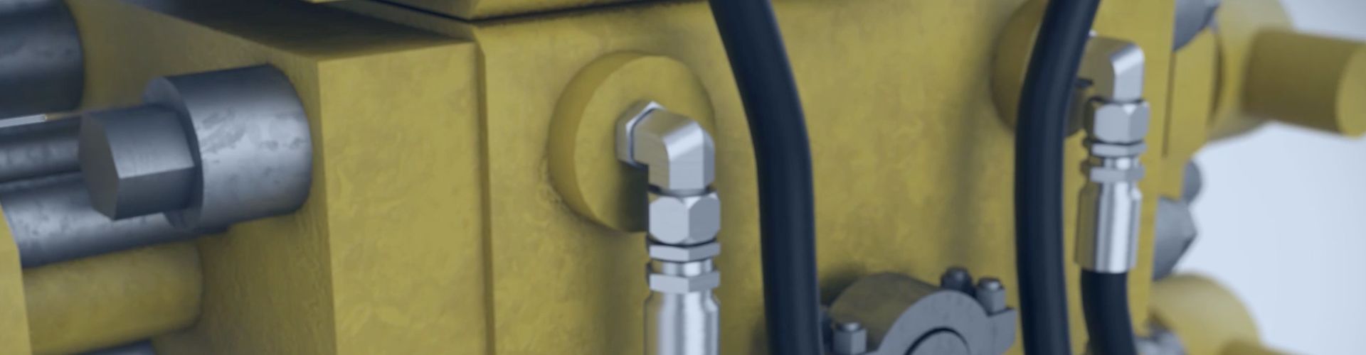
Hydraulic systems are the backbone of countless industrial and mobile
Hydraulic systems are the backbone of countless industrial and mobile
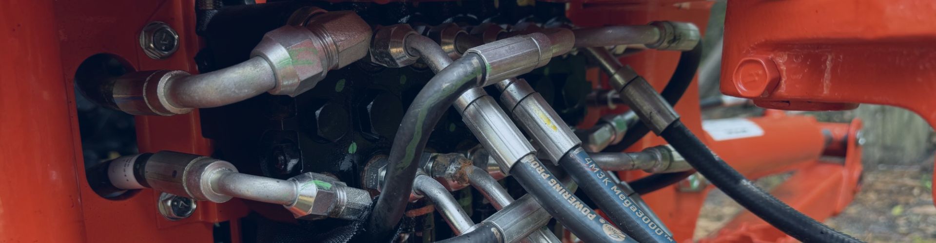
Hydraulic hoses, often overlooked in their apparent simplicity, are critical
From construction excavators to agricultural harvesters, these systems are constantly
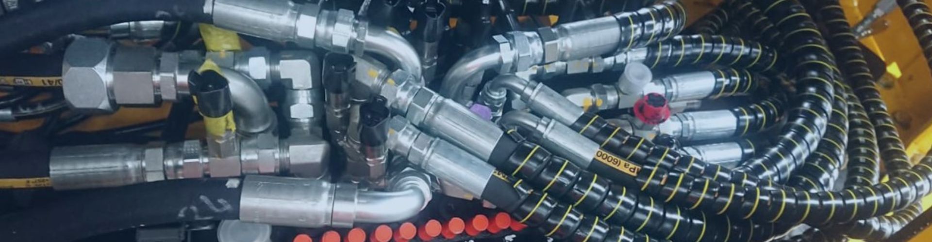
In the intricate world of industrial and mobile machinery, high-pressure
Hydraulic systems are the backbone of countless industrial, mobile, and

Introduction Hydraulic systems are vital for many industries, but their
Introduction In the realm of industrial operations, hydraulic systems are
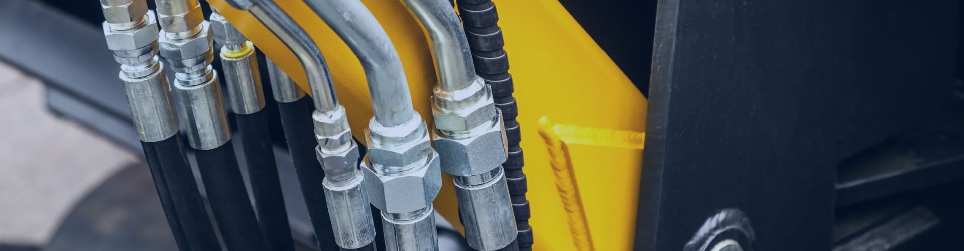
Introduction Hydraulic hose fittings are critical components in fluid power
Hydraulic systems are essential power transmission networks that drive critical
Leak-free hydraulic systems are paramount for safety, efficiency, and environmental