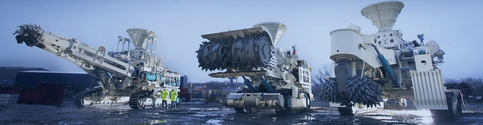
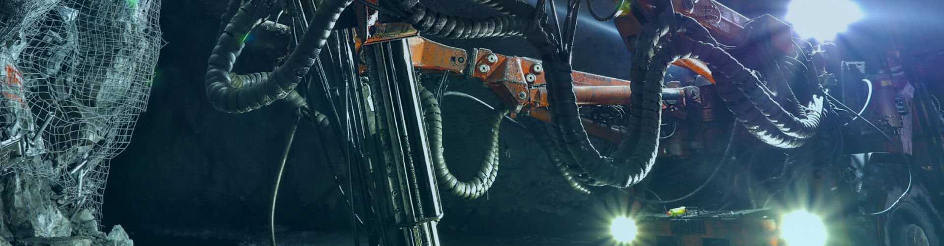
Advanced Hydraulic Fittings Selection: Marine & Mining
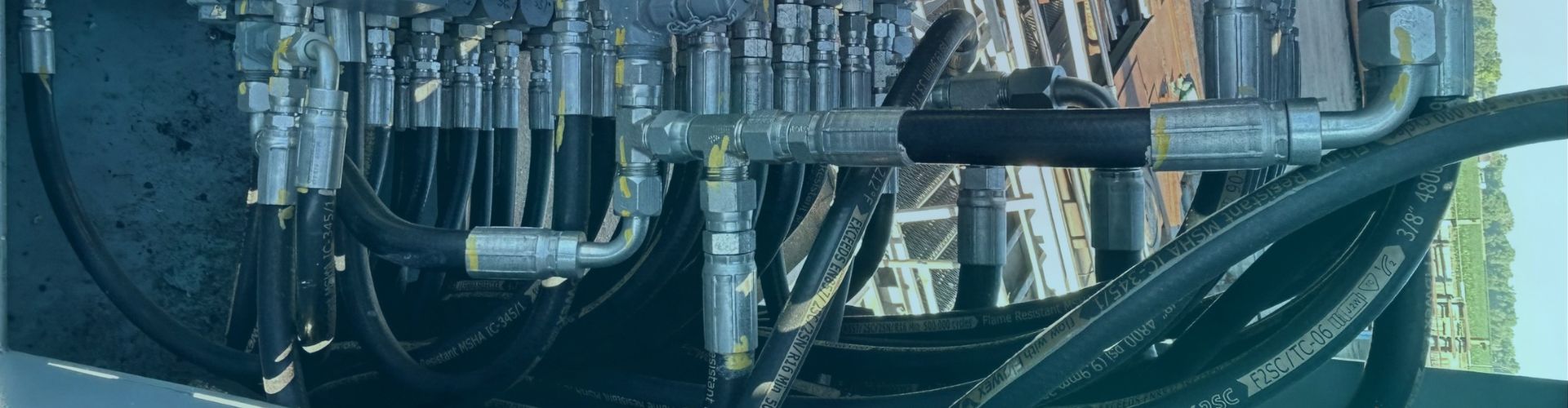
Hydraulic hose fittings serve as critical components in marine and
Hydraulic hose fittings serve as critical components in marine and
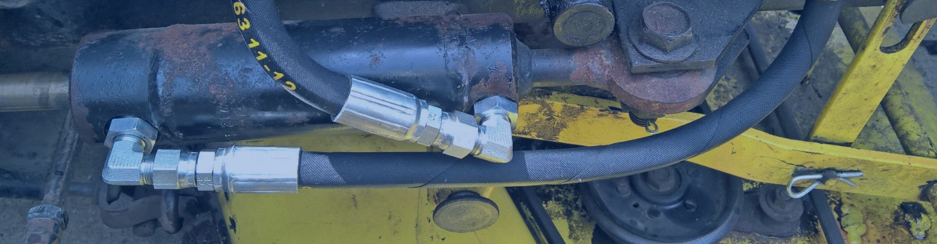
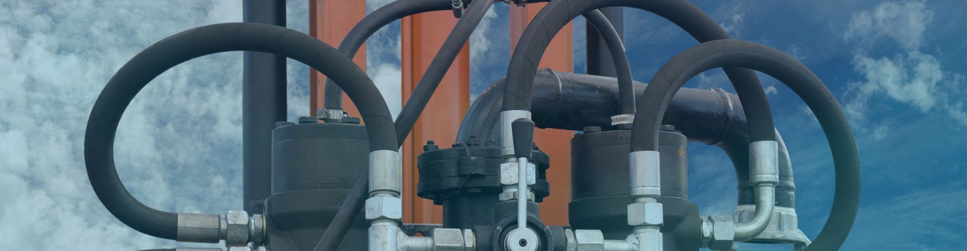
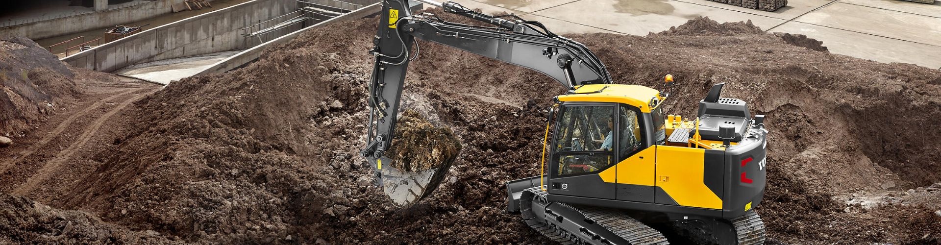
Hydraulic systems form the backbone of modern machinery across numerous
Hydraulic fittings are critical connection points in fluid power systems
Downtime eats profits—fast. Yet, most procurement managers still see hydraulic
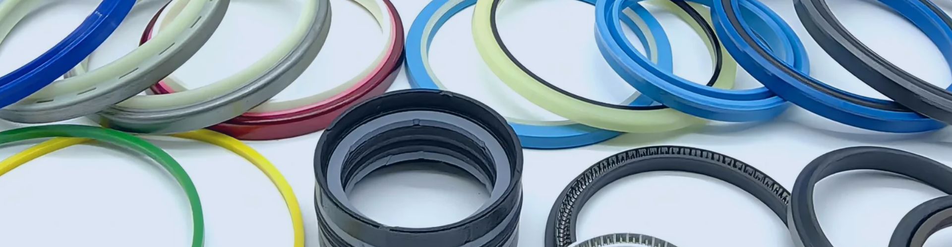
Hydraulic seals play a pivotal role in the efficiency and
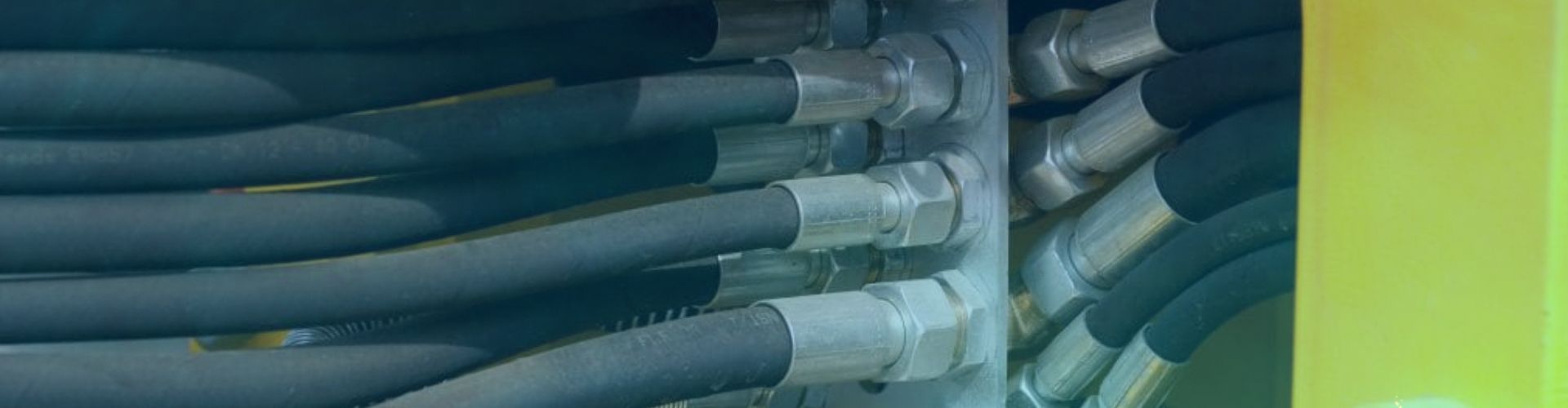
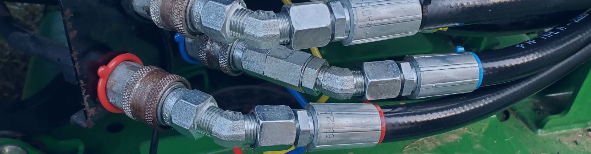
Hydraulic hose assemblies are the vital arteries of countless industrial
Failure to follow bend radius specifications can lead to catastrophic
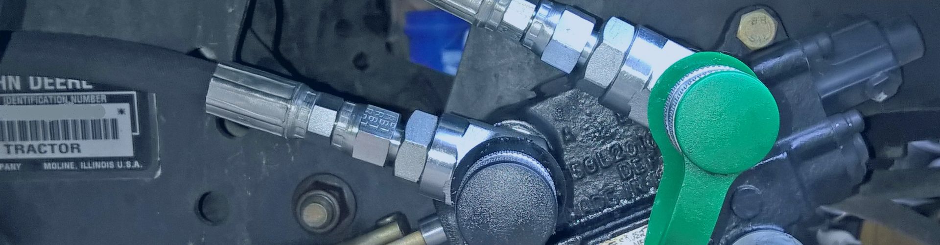
In manufacturing environments, even minor inefficiencies in fluid transport systems
Hydraulic cylinder, as a modern industrial equipment in the indispensable
Standard hydraulic fittings are often designed for general industrial applications