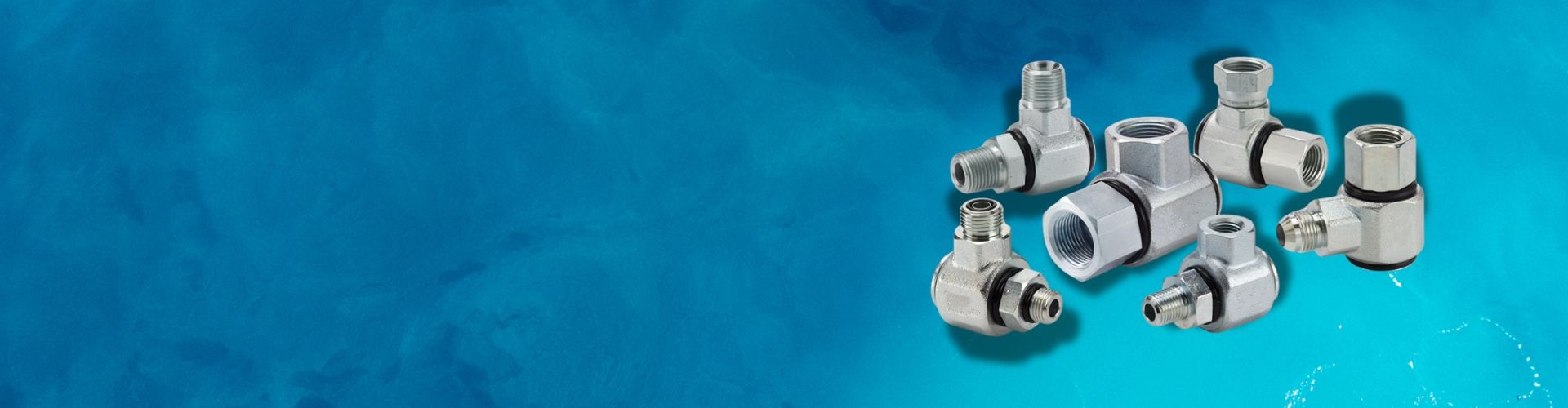
Hydraulic Swivel Fittings Design, Applications And Market Trends
Hydraulic swivel fittings, also known as live swivels, are essential
Hydraulic swivel fittings, also known as live swivels, are essential

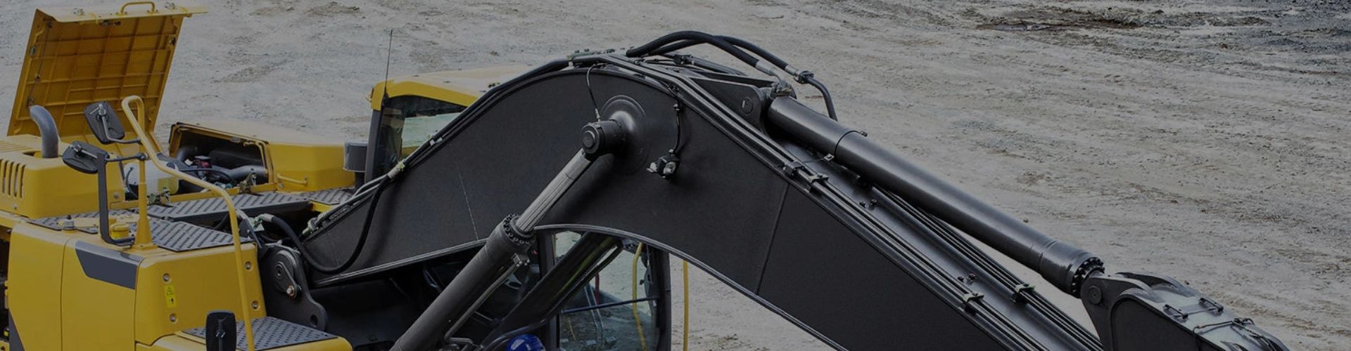
Hydraulic fittings are critical components in hydraulic systems, used to

Standard hydraulic fittings and hoses often fall short when faced

Choosing the right hydraulic cylinder is crucial for your machine’s

Hydraulic cylinders are the powerhouses of industry, delivering essential force
In hydraulic systems, every component plays a crucial role in

Hydraulic cylinders are essential components in various industries, driving equipment

Hydraulic cylinders are essential in many industrial applications, ensuring smooth,

In all kinds of industrial applications, hydraulic hoses play a

Introduction Hydraulic cylinders operate in extreme environments and face severe