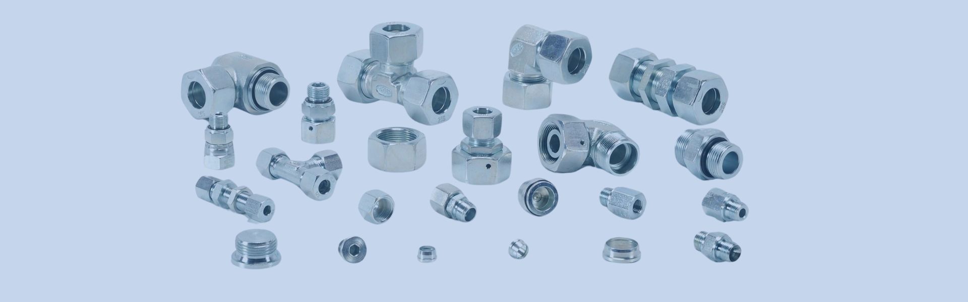
Stainless Steel Hydraulic Fitting Surface Treatment Types
Even though stainless steel has a natural resistance to rust
Even though stainless steel has a natural resistance to rust
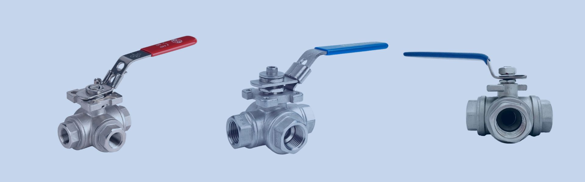
The two main types of ball valves—top entry and side
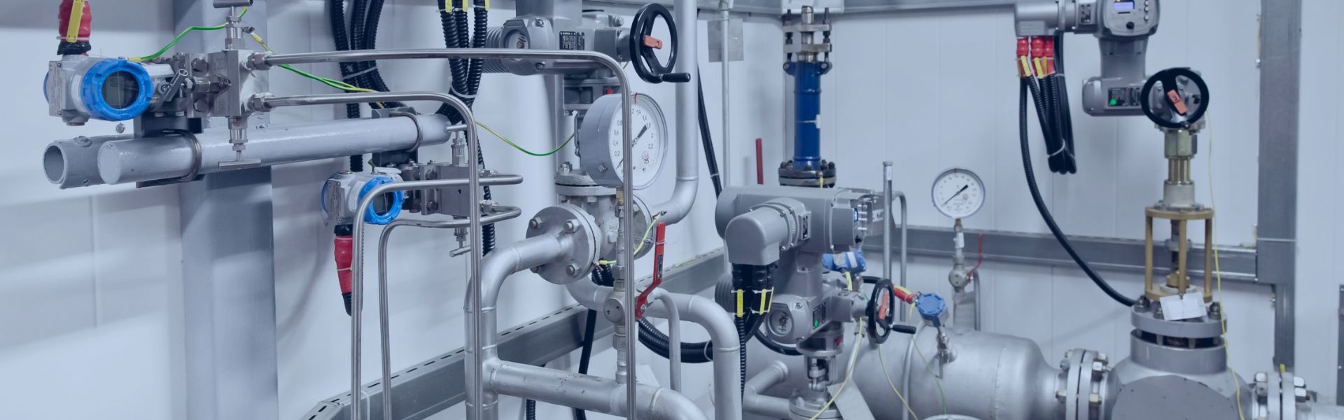
Imagine you are managing a complex industrial piping system where
Surface treatments are designed to improve key characteristics such as

Upgrading your valve system by replacing a gate valve with

A ball check valve is a type of one-way valve

Proper installation is the foundation of any efficient drip irrigation

When it comes to installing ball valves, getting the installation

Ball valves are designed to last a long time, but

Ball valve direction refers to the orientation of the flow