
Hydraulic Hoses Repair Guide: Patching, Binding, Splicing
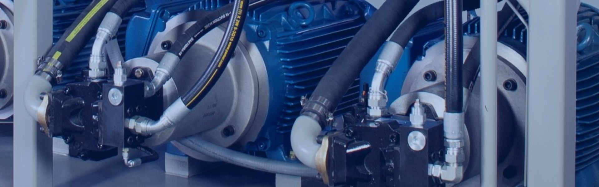
Hydraulic hoses are the lifelines of countless industrial and mobile
Hydraulic hoses are the lifelines of countless industrial and mobile

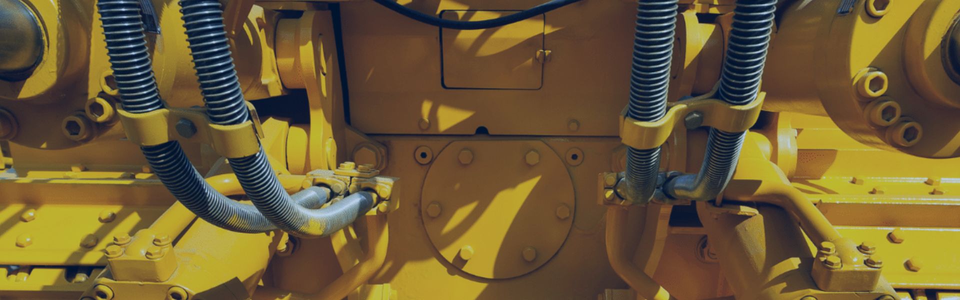
At 3:00 AM, a sudden hydraulic pump failure in a
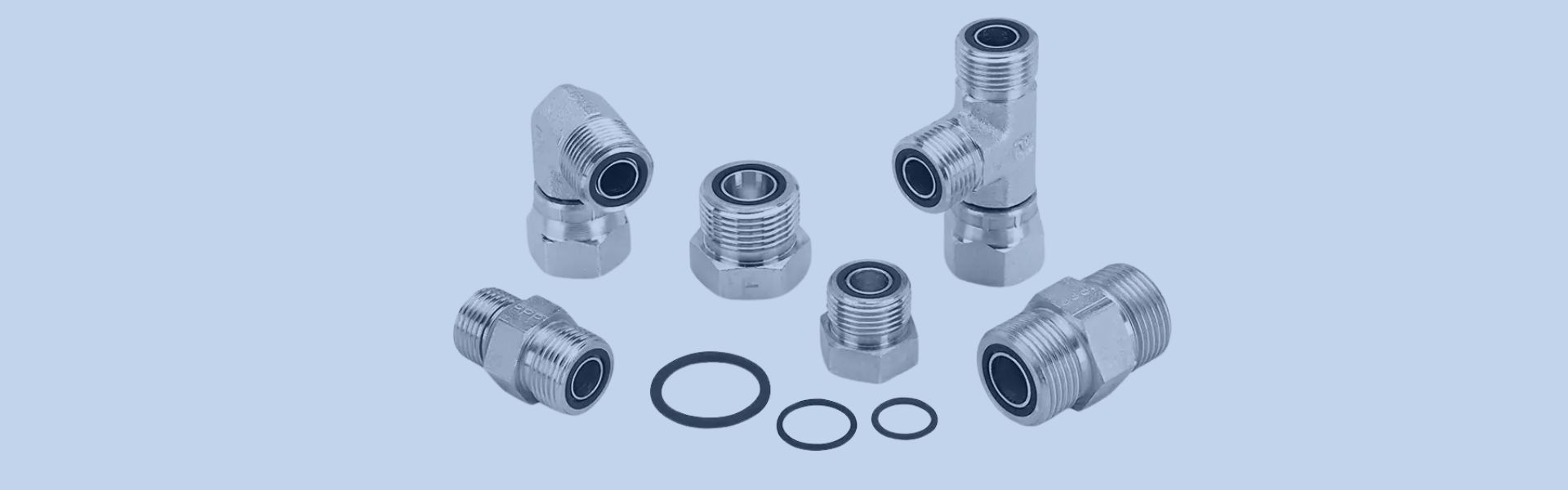
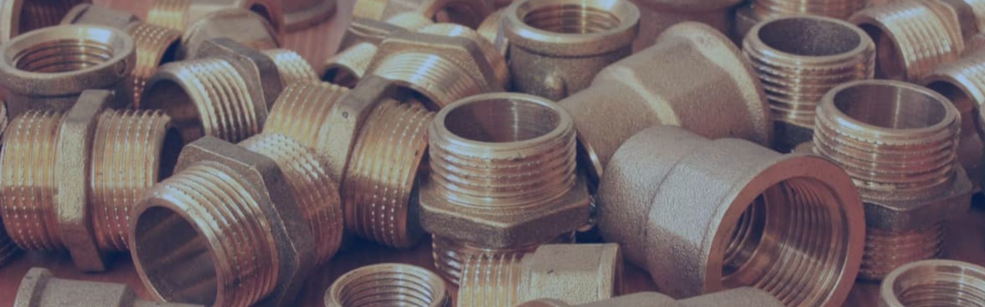
Hydraulic fittings (commonly referred to as hydraulic connectors) come in
These thread codes represent standards used by different countries or
Hydraulic hoses are crucial components in hydraulic systems, playing a
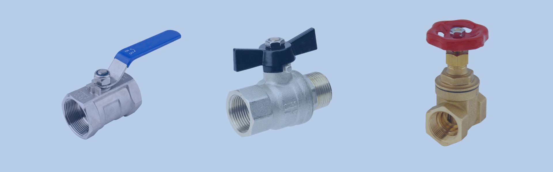
A ball valve’s mechanism consists of a spherical disc (the
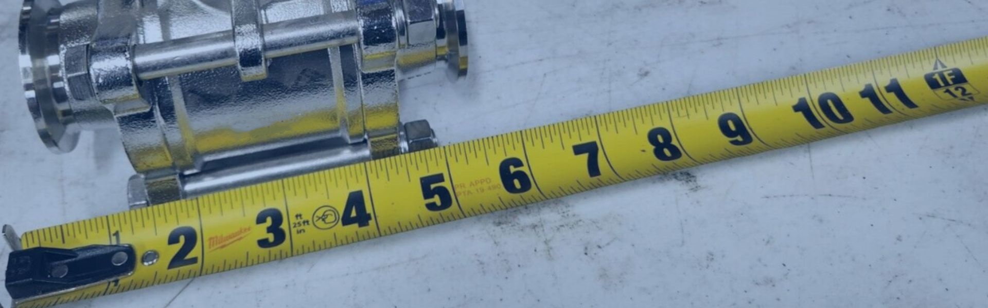
Choosing the right ball valve size is pivotal in ensuring
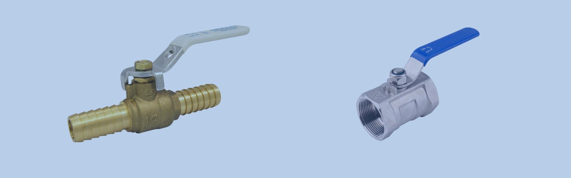
The specifications define the physical and operational characteristics of the
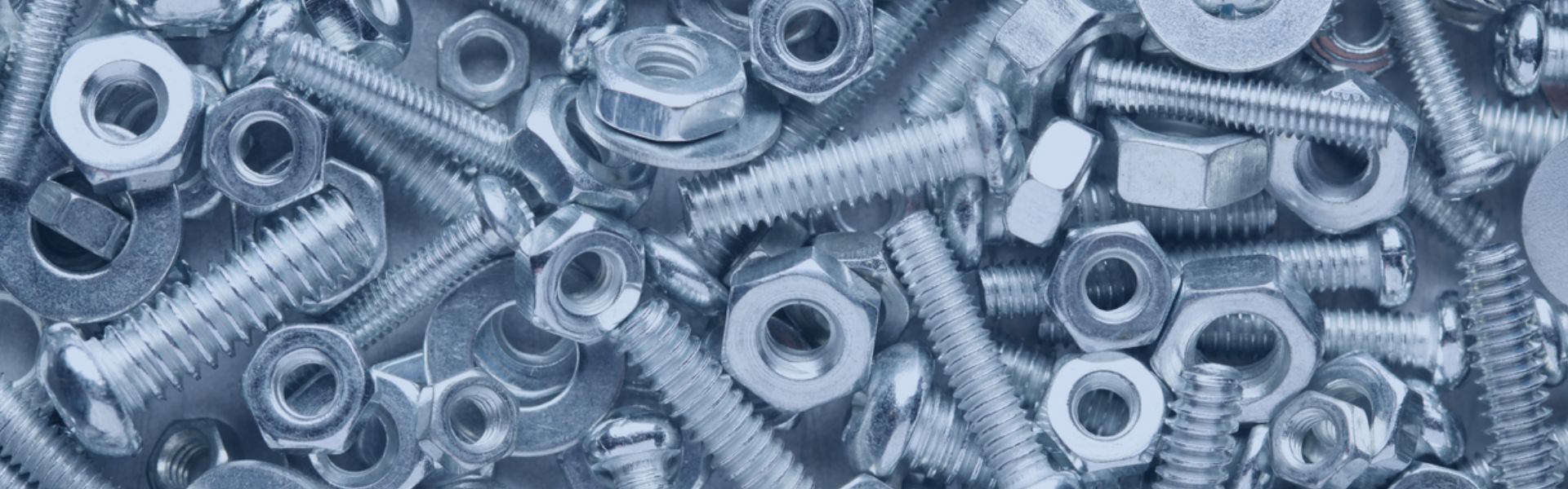
Aluminum fitting surface treatment is process used to enhance the
While brass itself is a resilient material, it is not