
Hydraulic Flange Standards: Key Global Variations
Imagine installing a brand-new hydraulic system—only to realize the flanges
Imagine installing a brand-new hydraulic system—only to realize the flanges
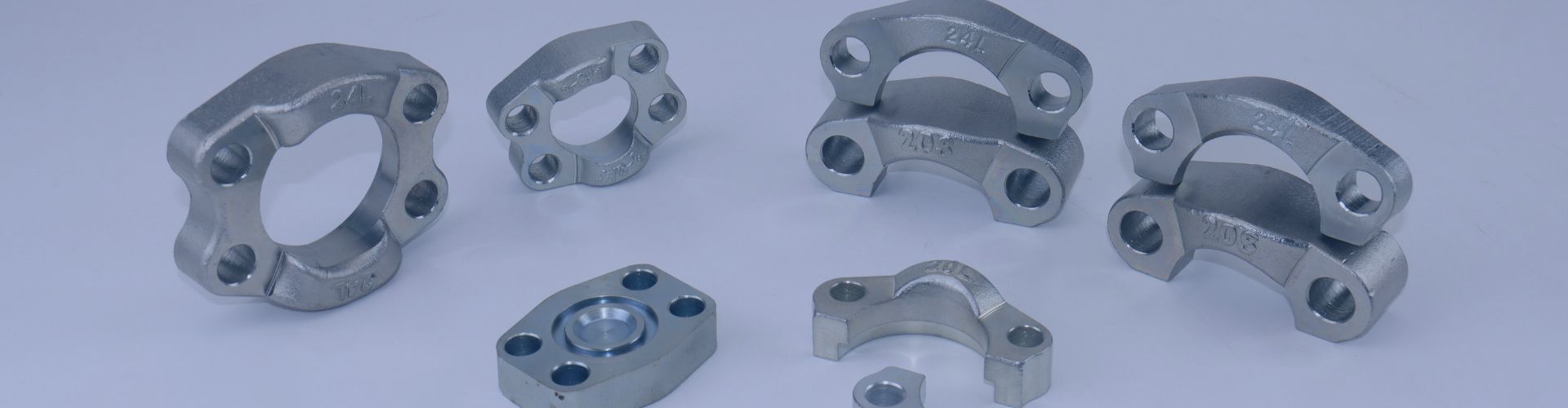
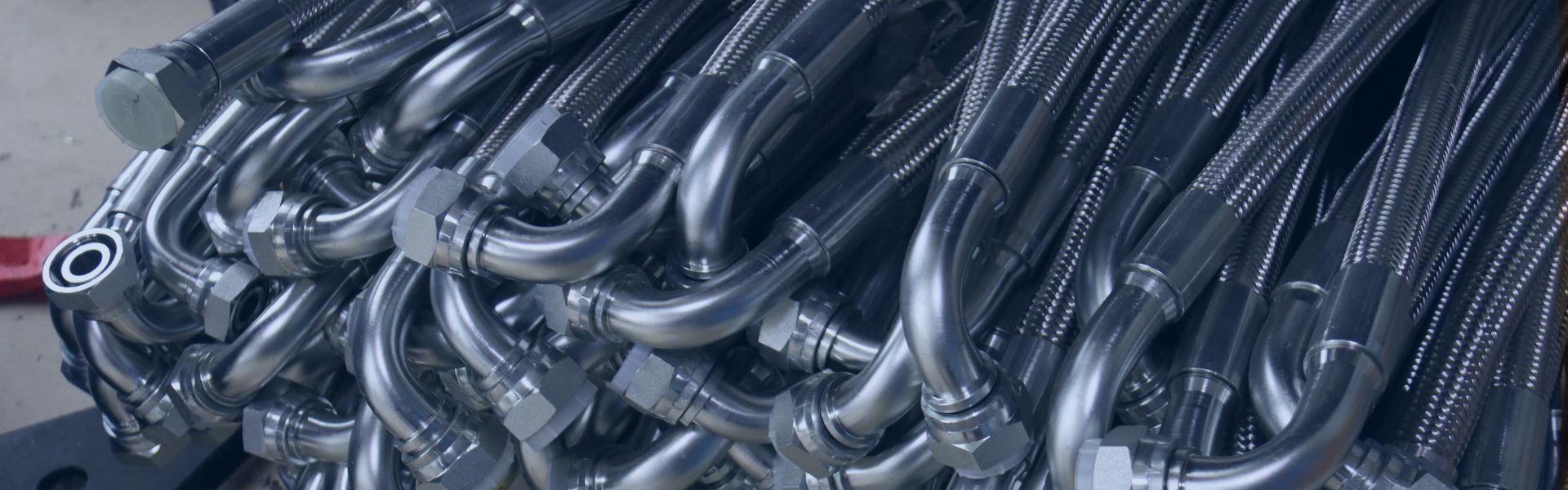
Flanges allow sections of a system to be joined or

In the intricate world of fluid control, selecting the right

Live swivel fittings represent a critical advancement in hydraulic system

In high-pressure industrial settings, hydraulic oil leaks remain a major
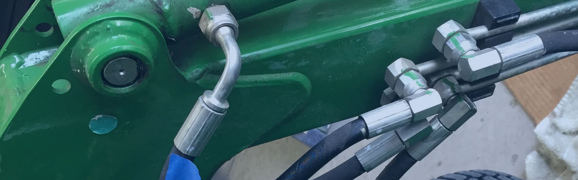
Hydraulic systems are vital in today’s industrial operations, yet loose
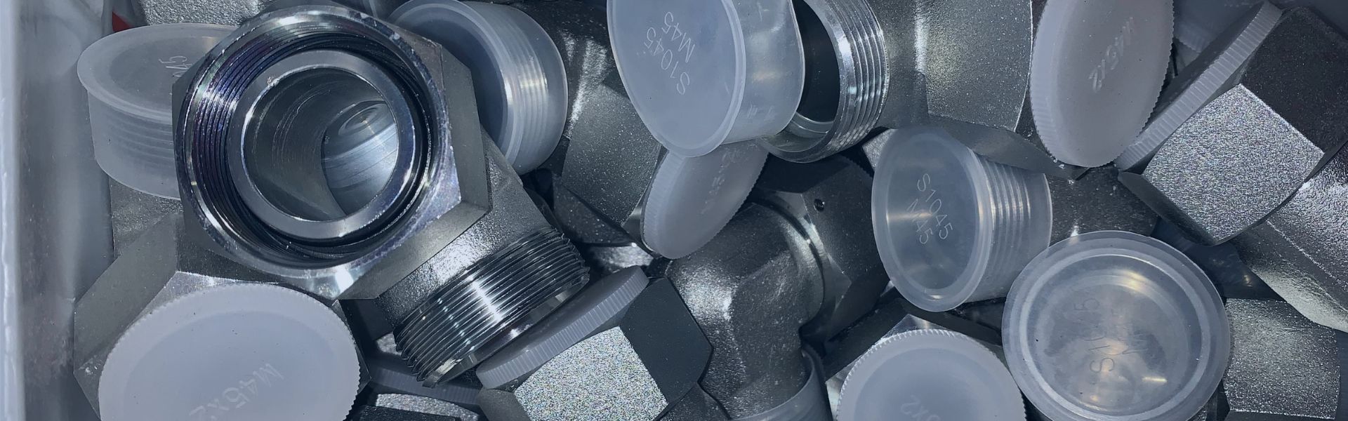
In the complex world of fluid power systems, hydraulic adapters
Hydraulic system performance critically depends on hose diameter selection, yet
The use of the wrong type of hydraulic fitting, a
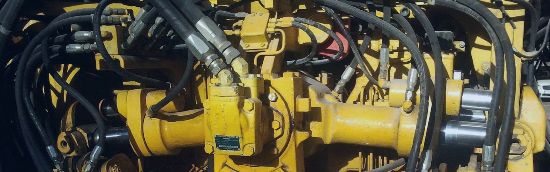
In today’s industrial world, hydraulic systems power countless operations across