
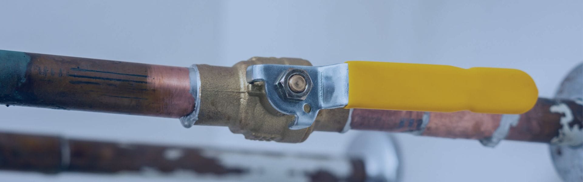
Ball Valve Direction: Understanding Flow Control Basics
Ball valve direction refers to the orientation of the flow
Ball valve direction refers to the orientation of the flow

Ball valves are crucial in fluid control systems, offering precise

Ball valves are critical in controlling the flow of liquids

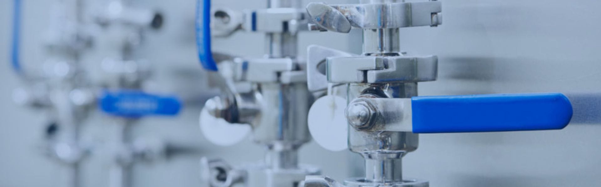
Full port ball valves, with a bore that matches the

A standout feature of full port ball valves is their

Full port ball valves have a bore that matches the

UNF threads, with their fine pitch, are ideal for applications
Over time, seals and valve seats can deteriorate, allowing small
In industries like oil and gas, chemicals, and power generation,

Pressure testing plays a vital role in confirming that hydraulic