
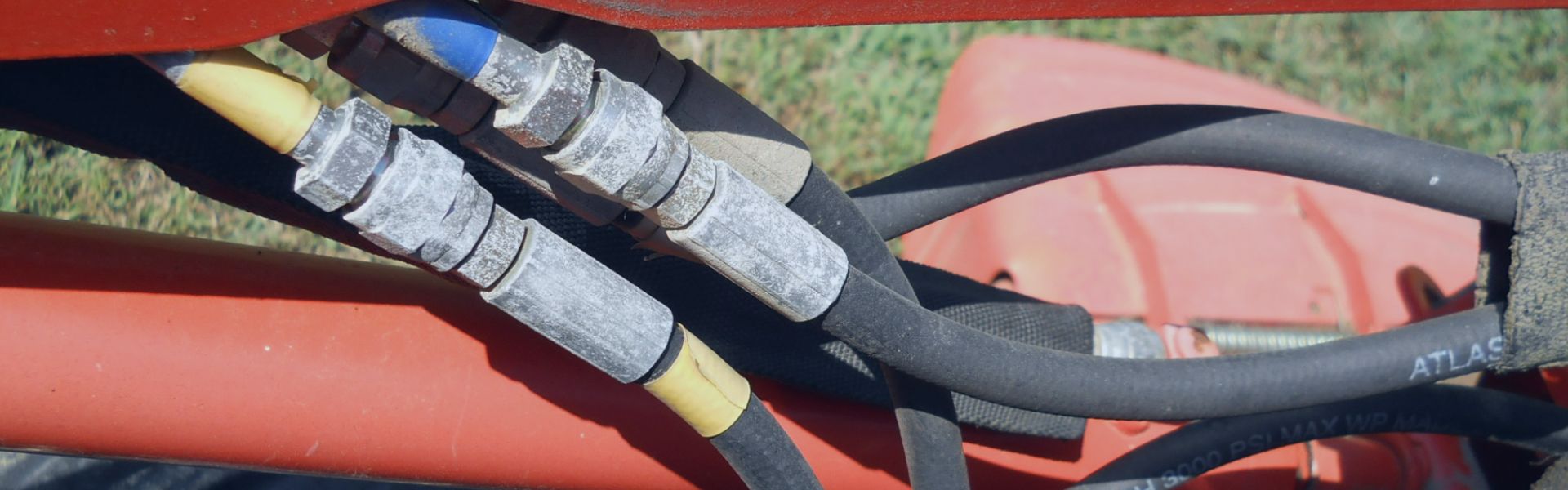
Hydraulic Hose Cleaning and Maintenance Methods
Given the demanding environment of hydraulic systems, maintaining hose cleanliness
Given the demanding environment of hydraulic systems, maintaining hose cleanliness

Choosing the right hydraulic seal is crucial for the optimal

Heat treatment of metal materials is a technology that changes

Hydraulic oil is a specially formulated fluid used in hydraulic

Steel heat treatment refers to a set of processes used
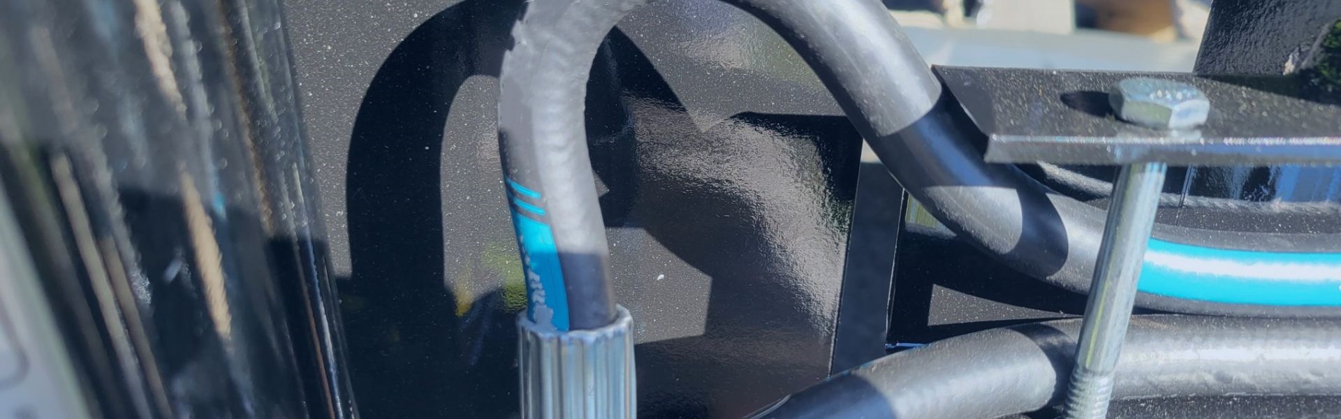
With the prolonged use of equipment, the hydraulic system may
The costs of neglected hose maintenance go beyond just repairing

Choosing the right hose material is crucial for your business
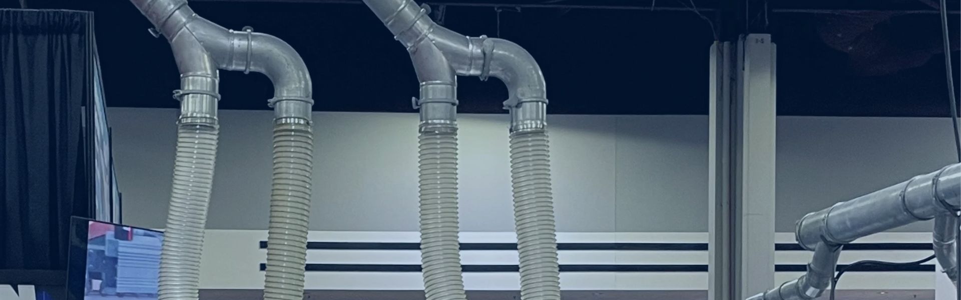
Industrial fluid systems rely on hoses to transport liquids and
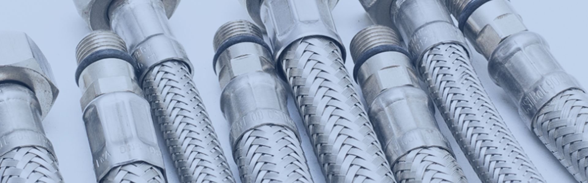
Hydraulic hose assemblies are essential components in hydraulic transmission systems.