
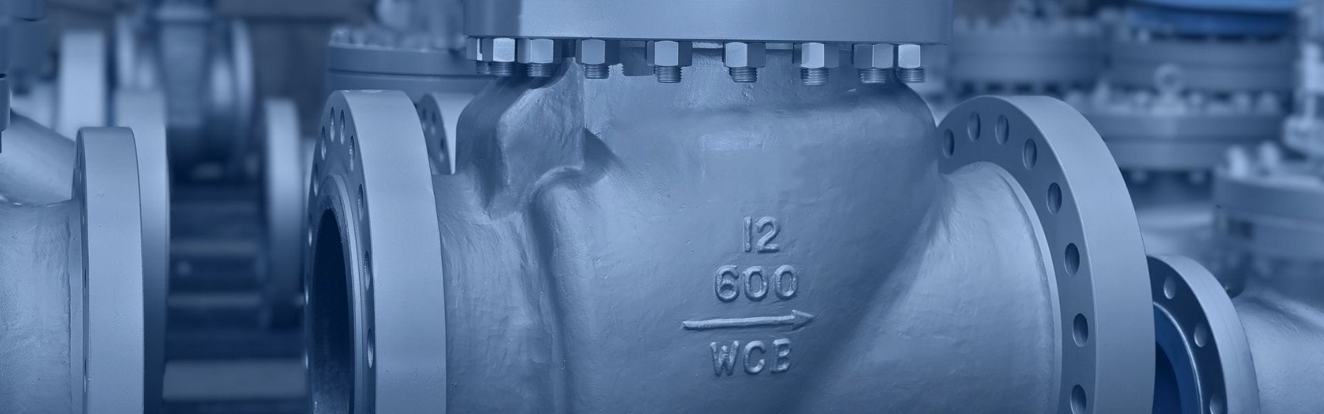
What is Pressure Drop in Hydraulic Systems?
Pressure drop refers to the reduction in pressure that occurs
Pressure drop refers to the reduction in pressure that occurs

In hydraulic systems, the correct installation of hoses and tubes
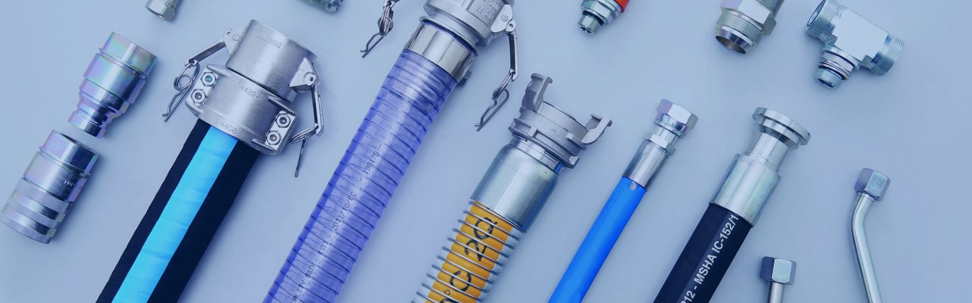
Industrial hoses play a crucial role in a wide range
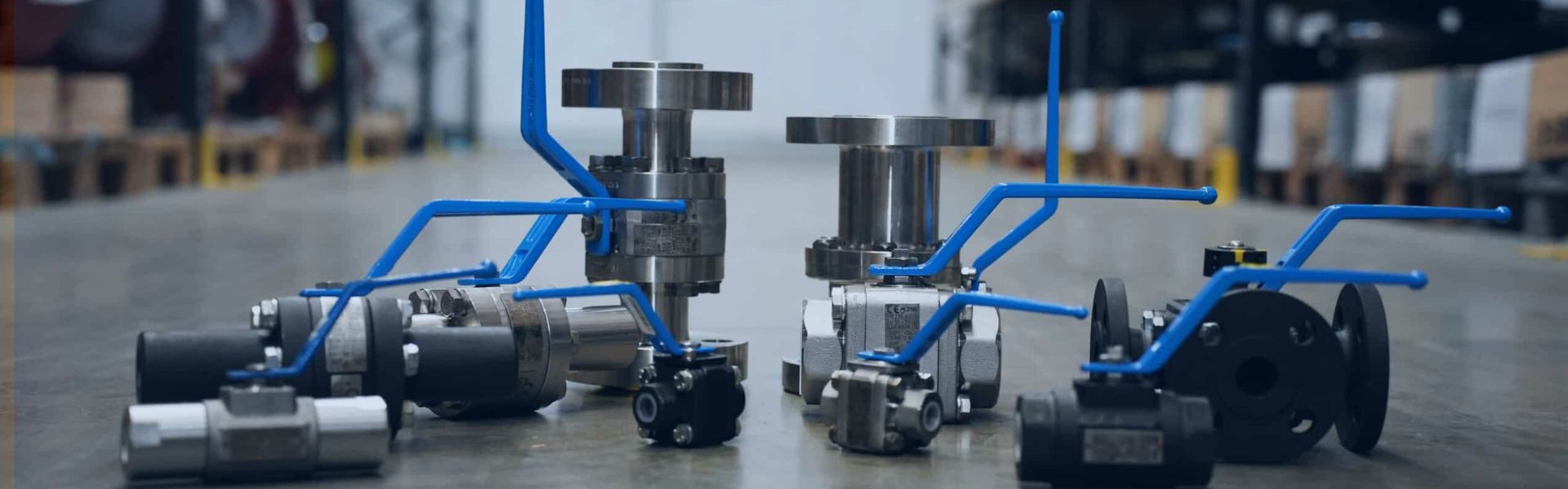
How do you choose the right valve? Let’s take a
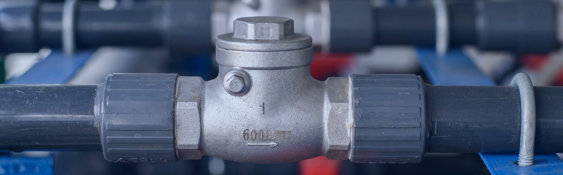
A ball check valve and a swing check valve are
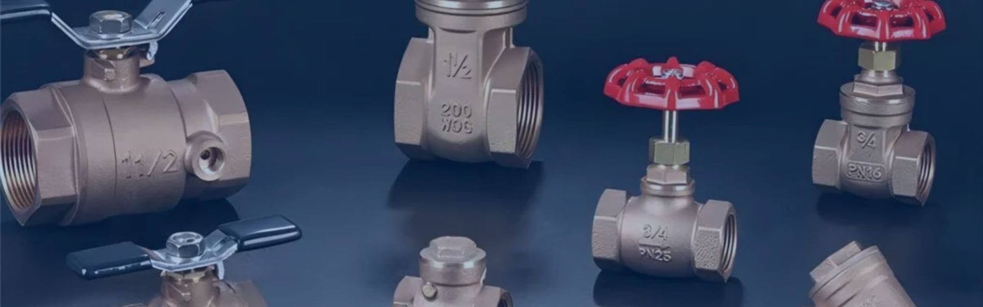
Why does the material matter so much? Well, different materials
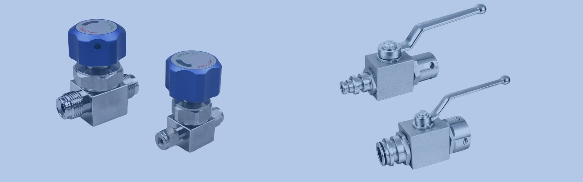
Both diaphragm and ball valves are designed to regulate the
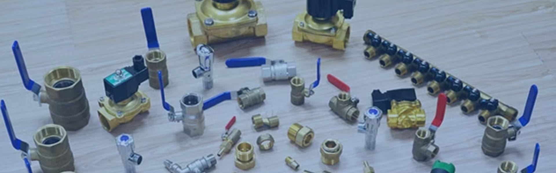
Valves are essential components in fluid systems, acting as gatekeepers
Ball valves are essential components used to control the flow
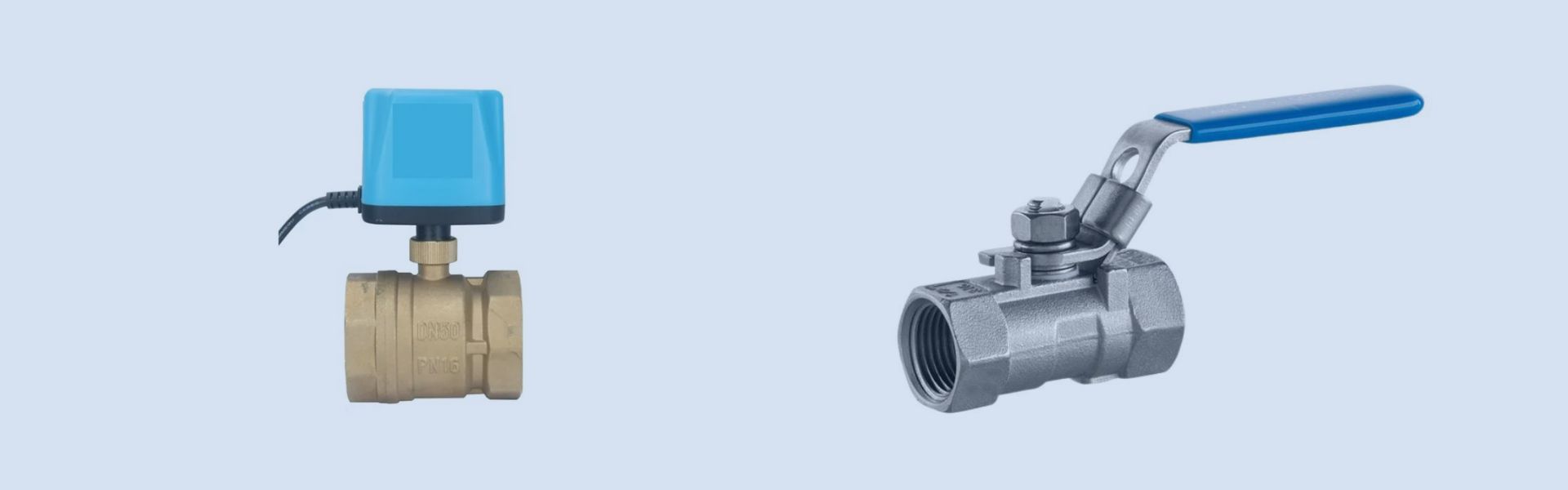
A solenoid valve is an electrically operated valve used to