Ball Valve vs Shut Off Valve: The Ultimate Comparison
When it comes to choosing the right valve for your
When it comes to choosing the right valve for your

A ball valve is a mechanical device used to control

Unlike traditional ball valves, which require precise measurements and threading,
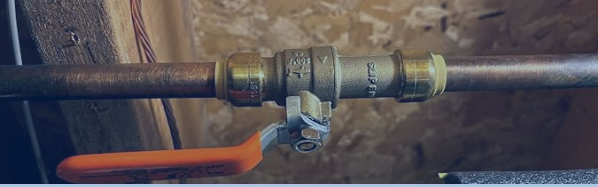
A slip ball valve is a type of valve commonly
Installing a ball valve into copper piping provides precise water
A ball valve is a type of quarter-turn valve that
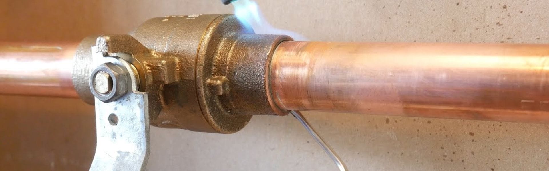
Misalignment between the ball valve and the copper pipe, insufficient
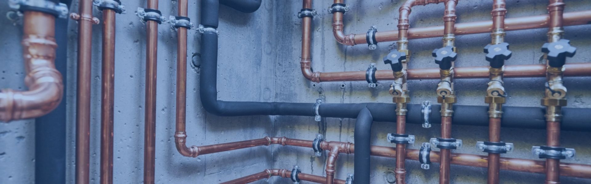
Fluid control systems are designed to manage the flow, pressure,
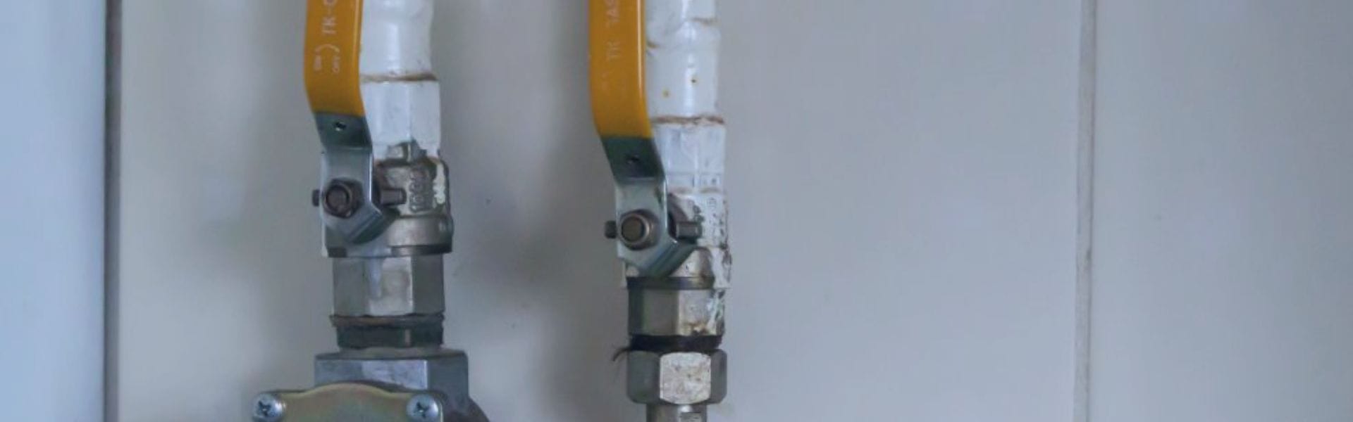
Ball valve allows for a tight seal, minimal flow resistance
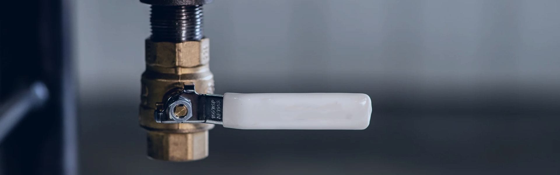
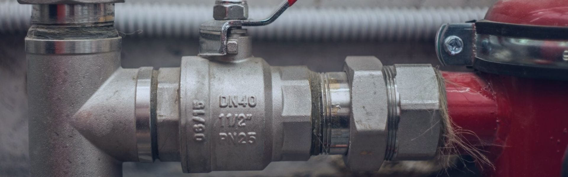
A proper understanding of a ball valve‘s markings and abbreviations