Ball Valve Installation: Common Issues and Fixes
A ball valve uses a spherical ball with a hole
A ball valve uses a spherical ball with a hole
Ball valve specification refers to the set of criteria and
The primary cause of a ball valve leaking from the
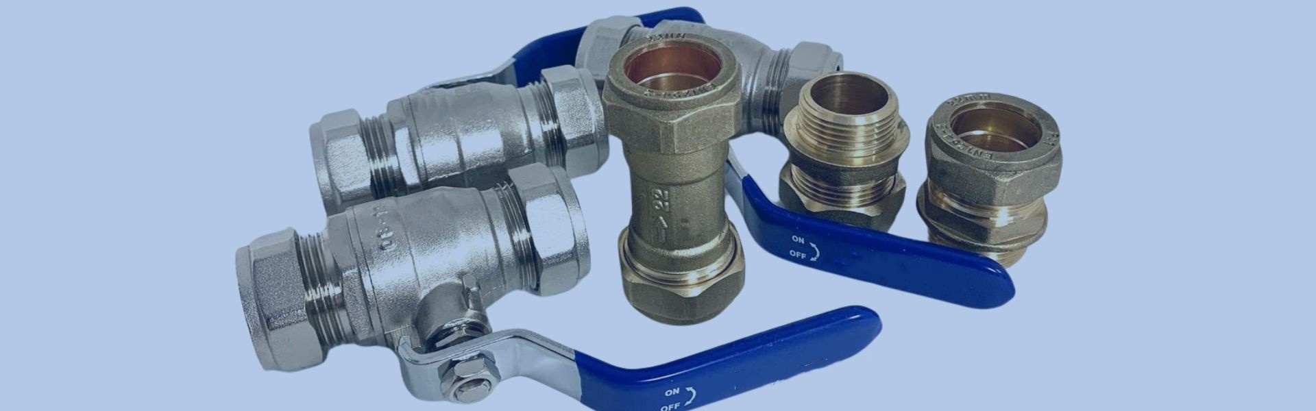
Ball valves are essential for fluid control due to their

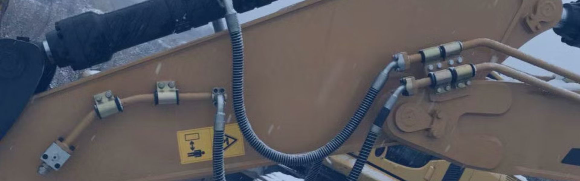
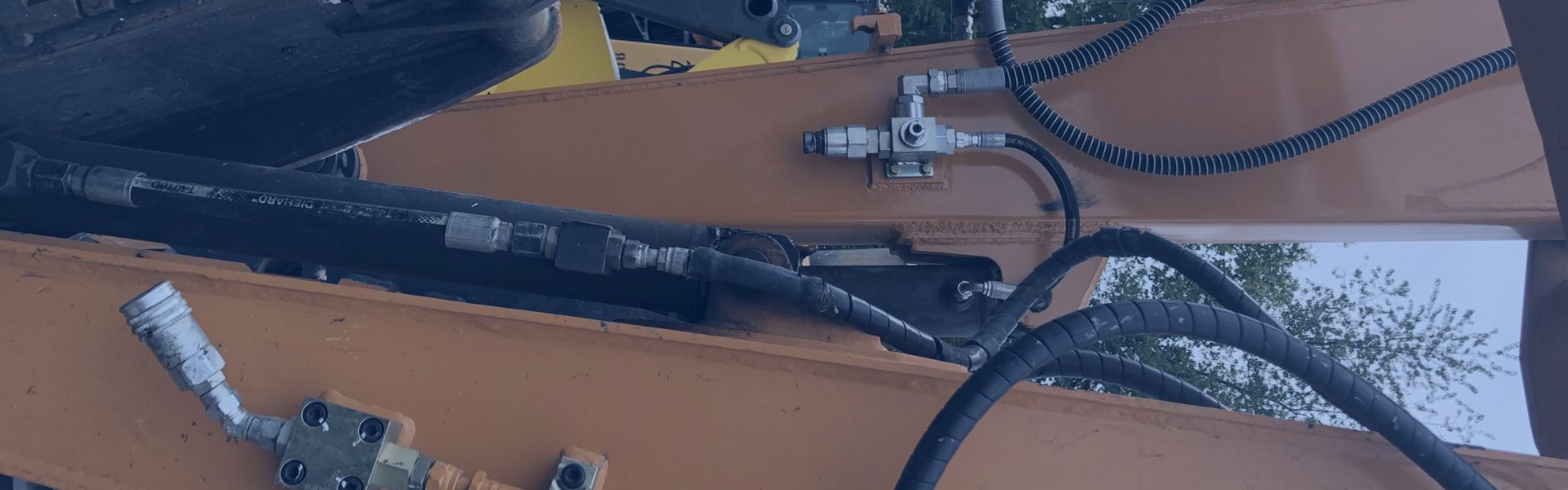
A hydraulic hose spiral layer is a specialized layer of
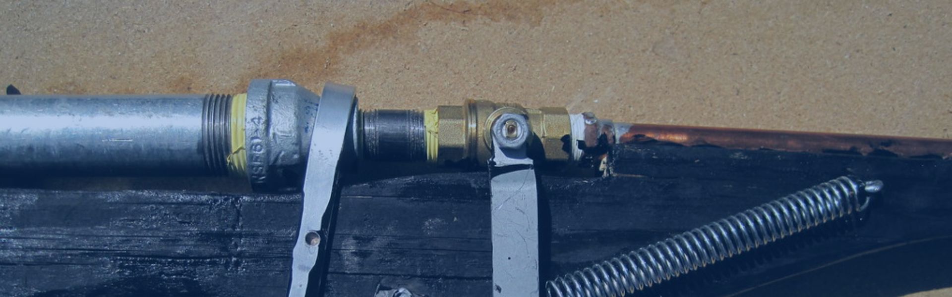
NPT thread specifications define the geometry, tolerances, and angle of
While both NPT and NPTF fittings may look similar, their
NPT, or National Pipe Tapered, fittings are a type of

Vulcanization is a chemical process that involves treating rubber or

The braid layer is a crucial component in the construction