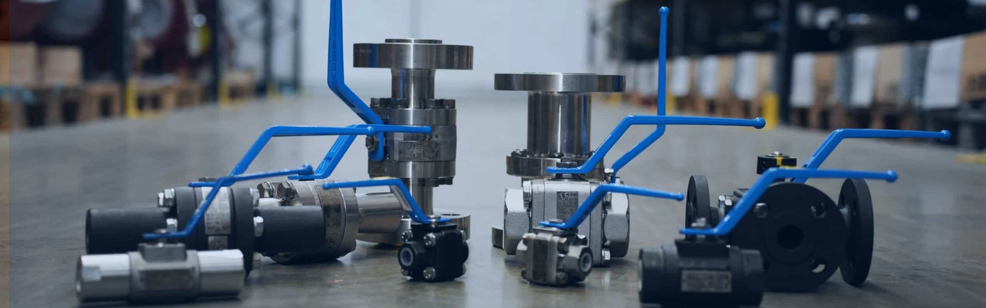
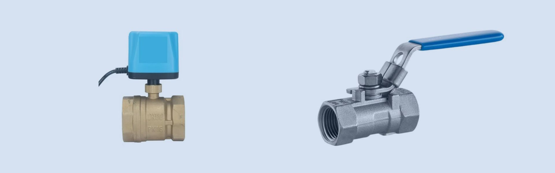
How to Stop a Dripping Ball Valve banner

How to Stop a Dripping Ball Valve

Over time, seals and valve seats can deteriorate, allowing small gaps that lead to leaks, while a worn valve stem or buildup of debris inside the valve can also interfere with its function. Even a seemingly minor leak can result in significant problems such as increased water waste, higher utility bills, water damage, decreased system efficiency, and negative environmental impact.

Signs Your Ball Valve is Leaking: How to Identify the Problem

How to Tell if Your Ball Valve is Leaking

Visible Drips or Water Pooling: The most obvious sign of a leaking ball valve is water dripping from the valve or pooling around the valve body. Check the valve area for any signs of moisture or puddles.

Low Water Pressure: A leaking valve can result in a noticeable drop in water pressure throughout your plumbing system. If you notice lower-than-normal pressure, it may indicate that the valve is leaking or not fully closing.

Hissing Sound: A subtle hissing sound near the valve could indicate a slow leak. This sound is often caused by air escaping due to pressure loss or a damaged seal.

Corrosion Around the Valve: If you spot rust, corrosion, or mineral buildup around the valve, it could be a sign that the valve has been leaking over time and causing damage to the surrounding area.

Symptoms of a Faulty Valve: Water Drips, Low Pressure, etc.

Persistent Dripping: Even if the valve is in the “off” position, a faulty ball valve may continue to drip water. This is often due to a worn-out seal or damaged valve components.

Intermittent Flow: If you notice an irregular flow of water, such as surges or drops in water pressure when using faucets or appliances, the ball valve could be the cause.

Difficulty Turning the Valve: If the valve handle feels stiff or difficult to turn, it could indicate internal damage or a clogged valve, which may lead to leaks when it’s in use.

Water Leaks Around the Valve Stem: If you see water leaking from the valve stem (the central shaft that opens and closes the valve), it’s a clear indication that the stem seal is damaged or the valve is improperly seated.

Dripping Ball Valve

Common Misconceptions About Leaking Ball Valves

“It’s Just a Little Drip, No Big Deal: While a small drip may seem insignificant, it can waste gallons of water and cause long-term damage to your plumbing system.

“A Leaking Valve Will Always Be Easy to Fix”: Many people assume that fixing a leaking valve is simple, but depending on the cause of the leak, repairs can range from straightforward to complex and may require specialized tools or replacement parts.

“Ball Valves Don’t Leak”: Some assume that ball valves, known for their tight seals, are immune to leaks. However, they can still suffer from wear and tear, especially with prolonged use or poor maintenance.

“The Leak Will Stop on Its Own”: Some believe that a dripping valve will eventually seal itself, but in reality, leaks tend to get worse over time and can lead to more serious issues like water damage or high utility bills.

Common Causes of a Dripping Ball Valve

Valve Seat Wear and Tear

What is the Valve Seat?: The valve seat forms the seal between the ball and the valve body, ensuring that water stays contained when the valve is closed.

Why It Wears Down: Constant pressure and friction from the ball can cause the valve seat to wear down over time, leading to leaks when the valve is in the “closed” position.

How to Spot Seat Damage: If the valve drips when closed, it could be a sign that the seat is no longer providing a tight seal. Look for uneven wear or visible damage in the seat area.

Worn-Out or Damaged Ball Valve Seals

Function of the Seals: Ball valve seals are designed to prevent leaks by creating a watertight barrier between the valve components.

How Seals Get Damaged: Exposure to extreme temperatures, water pressure fluctuations, or chemical reactions can cause seals to degrade, crack, or harden, resulting in a dripping valve.

Signs of Seal Damage: If you notice water dripping around the valve stem or from the valve handle, it’s likely that the seals are compromised and need replacing.

Issues with the Valve Stem or Gasket

Valve Stem Wear: The valve stem is the part that connects the handle to the ball inside the valve. Over time, the stem can become loose or damaged, leading to water leakage at the stem area.

Gasket Failures: The gasket around the valve stem is crucial in maintaining a leak-proof seal. If the gasket becomes worn or damaged, it can allow water to leak through the valve stem.

How to Check for Stem and Gasket Issues: Tighten the valve handle or inspect the stem area for any signs of loose fittings or corrosion. If the leak persists, the stem or gasket may need replacing.

Debris and Mineral Buildup Causing Leaks

How Debris Affects the Valve: Dirt, sand, and other debris can get trapped inside the ball valve, preventing the ball from fully closing. This can create gaps that lead to leaking.

Mineral Deposits: Hard water can leave behind mineral deposits like calcium, which can build up inside the valve and interfere with the sealing surfaces, causing a drip.

Cleaning and Maintenance: Regular cleaning and flushing of the valve can help prevent debris buildup. If you live in an area with hard water, installing a water softener can also help reduce mineral deposits.

Improper Installation or Maintenance Errors

Incorrect Valve Installation: If a ball valve is improperly installed, it may not function correctly, leading to leaks. Common issues include improper orientation, misaligned components, or failure to use appropriate sealants or lubricants.

Maintenance Mistakes: Skipping regular maintenance or using the wrong tools during repairs can cause valve parts to become damaged or improperly sealed. It’s crucial to follow proper installation and maintenance guidelines to avoid leaks.

How to Avoid Installation Errors: Always ensure the valve is installed according to manufacturer instructions. Use proper tools and materials to prevent damaging delicate components during repairs.

Step-by-Step Guide: How to Stop a Dripping Ball Valve

Step 1: Turn Off the Water Supply

Locate the Shutoff Valve: Before starting any repair work, make sure to turn off the main water supply to avoid any unwanted water flow during the process.

Verify the Shutoff: Open a nearby faucet to ensure the water is fully turned off and there’s no pressure in the pipes. This step is critical for preventing potential flooding or additional damage.

Test a Dripping Ball Valve

Step 2: Inspect the Valve and Identify the Leak Source

Visual Inspection: Examine the ball valve closely to spot any visible signs of leaks, such as water pooling, rust, or corrosion around the valve body.

Check for Drips: Determine whether the leak is coming from the valve stem, the valve body, or the ball valve seat. This will help pinpoint whether the seals, gaskets, or other components need replacement.

Test the Valve Movement: Try turning the handle to see if it moves smoothly or if it feels loose or misaligned. If the handle is difficult to turn or feels unbalanced, this could indicate internal wear or damage.

Step 3: Tighten the Ball Valve Stem

Locate the Stem Nut: The valve stem is the part that connects the handle to the internal mechanism of the valve. If the valve is dripping around the stem, it could be because the stem nut is loose.

Use the Right Tools: Using an adjustable wrench, carefully tighten the stem nut. Don’t overtighten, as this could cause additional damage. Tightening the stem can often stop minor leaks caused by loose components.

Check for Improvements: After tightening, check again for leaks to see if this simple adjustment resolves the issue. If the leak persists, you may need to move on to replacing internal parts like seals or gaskets.

Step 4: Replace Worn-Out Seals and Gaskets

Remove the Valve Handle and Stem: Once the valve is fully inspected, carefully disassemble the valve to access the seals and gaskets. This will likely involve removing the handle and unscrewing the valve stem.

Check for Damage: Examine the seals and gaskets for any visible damage or wear. If you find cracks, tears, or hardened rubber, these components will need to be replaced.

Install New Seals/Gaskets: Replace the old seals with new ones of the same size and material. Be sure to install them correctly to create a tight seal and prevent future leaks.

Step 5: Clean the Valve Parts and Check for Debris

Clean the Valve Body: Before reassembling, use a soft cloth or brush to clean the valve body and components. Remove any dirt, debris, or mineral buildup that could hinder the proper sealing of the valve.

Check for Blockages: Ensure that no debris or mineral deposits are obstructing the internal parts of the valve, especially around the ball, seals, or valve seat. Cleaning the components will also help prevent future leaks.

Lubricate if Necessary: Apply a small amount of valve lubricant to the valve stem and the seals if recommended by the manufacturer. This can help maintain smooth operation and prevent wear.

Step 6: Test the Valve After Reassembly

Reassemble the Valve: After cleaning and replacing any worn parts, carefully reassemble the valve by reversing the disassembly steps. Ensure everything is tightened securely, but avoid overtightening.

Turn the Water Back On: Slowly turn the water supply back on and check for leaks. Open the valve fully and test for proper functionality by checking for water flow and pressure.

Monitor for Drips: After a few minutes, closely inspect the valve area to ensure that no drips or leaks persist. If the problem is fixed, your ball valve should now be leak-free. If it continues to drip, further repairs or a valve replacement may be needed.

Preventative Maintenance: How to Avoid Future Leaks

How to Maintain Your Ball Valve for Long-Term Performance

Regular Valve Operation: Even if you’re not using the valve often, operate it periodically (e.g., once a month) to ensure the internal components don’t seize or stiffen. This helps maintain smooth operation and prevents valve parts from sticking.

Avoid Over-Tightening: While it may seem tempting to tighten the valve excessively to prevent leaks, over-tightening can damage seals and gaskets. Tighten only to the recommended torque.

Check for Alignment: Ensure that the ball valve is properly aligned with the pipes and doesn’t undergo undue stress or misalignment, which could cause premature wear.

Regular Inspection Tips to Catch Leaks Early

Visual Inspections: Regularly check for visible signs of leaks, such as moisture around the valve body, rust, corrosion, or water stains near the valve area.

Pressure Checks: Test the water pressure regularly. A drop in pressure could indicate a hidden leak somewhere in your system, including the ball valve.

Listen for Hissing Sounds: Periodically listen for any faint hissing sounds around the valve, which might indicate a slow leak or air escaping due to a faulty seal.

Monitor Water Usage: Keep an eye on your water bill. A sudden increase without a clear reason can be a red flag that there’s a hidden leak somewhere, including at the ball valve.

How to Clean and Lubricate Ball Valves for Smooth Operation

Clean the Valve Components: Over time, mineral deposits and debris can build up inside the valve, causing leaks or impairing function. Use a soft brush to remove any dirt, buildup, or rust from the valve body and seals.

Use the Right Lubricant: Apply a non-petroleum-based lubricant to the ball valve stem and seals to reduce friction and prevent them from wearing out prematurely. Ensure the lubricant is compatible with your water supply and materials.

Inspect Valve Seals and Gaskets During Cleaning: While cleaning, carefully check for cracks or deterioration in the seals and gaskets. If they appear damaged, it’s time to replace them to prevent future leaks.

Lubricate Moving Parts: Ensure that the valve handle and stem are well-lubricated to avoid stiffness or difficult operation. This will ensure smooth and effective valve control when needed.

Conclusion

To keep your ball valve leak-free and ensure its longevity, timely repairs are crucial. Even a small leak can lead to significant issues like water damage, higher utility bills, and reduced system efficiency, so addressing problems promptly helps avoid costly repairs and maintain the integrity of your plumbing system.


FAQ

What causes a ball valve to drip?

A ball valve can drip due to worn-out seals, gaskets, or a damaged valve seat. Additionally, mineral buildup, improper installation, or valve stem issues can also lead to leaks.

How can I stop a dripping ball valve without replacing it?

To stop a dripping ball valve without full replacement, first inspect and tighten the valve stem, clean any debris, and replace worn-out seals or gaskets. If the leak persists, consider replacing the valve seat or other damaged parts.

Can I fix a dripping ball valve myself?

Yes, you can fix a dripping ball valve yourself if you have basic plumbing tools and knowledge. Follow the proper steps to shut off the water supply, inspect the valve, and replace any damaged components like seals or gaskets.

How often should I check my ball valve for leaks?

It’s a good idea to inspect your ball valve at least once a year. Regularly check for visible leaks, corrosion, or changes in water pressure, especially if the valve is in frequent use or exposed to harsh conditions.

Is a dripping ball valve dangerous?

While a dripping ball valve might not be immediately dangerous, it can lead to water damage, rust, and mold over time. It’s important to fix the leak to avoid these potential issues and maintain the efficiency of your plumbing system.

What tools do I need to repair a leaking ball valve?

To repair a leaking ball valve, you’ll need basic plumbing tools such as a wrench, screwdriver, pipe sealant, replacement seals or gaskets, and potentially a valve seat kit. Make sure you have the right parts for your specific valve model.

Ball Valves for Hazardous Locations banner

Ball Valves for Hazardous Locations: Key Adaptations Explained

In industries like oil and gas, chemicals, and power generation, ball valves serve as a lifeline to prevent potentially disastrous accidents. So, why exactly are these valves irreplaceable in hazardous locations?

What Makes a Location Hazardous?

Defining Hazardous Locations: Explosion, Fire, and Chemical Risks

Explosion Hazards: Locations, where flammable gases, vapors, or dust are present in high concentrations, pose a serious risk of explosion. These locations are classified based on the likelihood of an explosive atmosphere occurring. Key examples include oil and gas refineries, chemical manufacturing plants, and grain elevators.

Fire Hazards: Areas where combustible materials, high temperatures, or open flames could cause ignition also fall under hazardous locations. Industries such as petrochemical processing or pharmaceutical production often face these risks.

Chemical Hazards: Hazardous locations may also involve environments with harmful or corrosive chemicals, where the use of specific valve materials and designs is necessary to avoid leaks or contamination. These locations often require valves made from materials resistant to both the chemicals they handle and any external ignition sources.

The Importance of Compliance with Safety Standards

ATEX Certification: The ATEX directive (European Union) ensures that equipment used in explosive atmospheres is safe to prevent ignition. ATEX-compliant ball valves are specifically designed to meet stringent safety regulations, making them indispensable in industries where explosive gases or dust are present.

NFPA Standards: The National Fire Protection Association (NFPA) sets safety standards for hazardous locations in the U.S. NFPA-rated valves are designed to minimize fire risks by preventing heat buildup, leakage, and spark generation.

UL Listings: Underwriters Laboratories (UL) certifies equipment used in hazardous locations for its safety performance. UL-rated ball valves assure that the valves meet or exceed specific safety criteria, such as preventing electrical sparks or isolating dangerous gases in industrial applications.

Environmental Factors That Influence Valve Design

Temperature Extremes: In hazardous locations, ball valves must operate in environments with extreme heat or cold. Materials such as stainless steel, carbon steel, or specialized alloys are used to ensure that the valve can handle temperature fluctuations without degrading or malfunctioning.

Pressure Fluctuations: High-pressure environments, such as deep-sea oil drilling or high-pressure gas pipelines, require valves that can withstand significant pressure without risking failure. Valve bodies and seals must be reinforced to handle the added stress.

Corrosive Environments: Exposure to harsh chemicals or corrosive substances can compromise the integrity of standard ball valves. In these settings, corrosion-resistant materials like brass, bronze, or plastic-lined valves are often used to ensure the valve’s longevity and safe operation.

Dust and Particle Risks: In certain hazardous locations, such as grain storage or mining sites, fine particles or dust in the air can increase the risk of ignition. Valve designs in these environments often include additional sealing and dust-proof features to prevent particles from coming into contact with ignition sources.

Explosion-Proof Ball Valves: How They Keep You Safe

What Makes a Ball Valve Explosion-Proof?

Design Features: Explosion-proof ball valves are engineered to prevent the ignition of flammable gases, vapors, or dust that may come into contact with the valve. Key features include:

Sealed Construction: These valves are constructed with tight seals to avoid leaks of potentially explosive materials.

No Sparks: Materials used in explosion-proof valves are chosen for their ability to resist spark formation, even under high pressure or when undergoing mechanical stress.

Specialized Actuators: Actuators used in explosion-proof valves are designed to prevent sparks and reduce the risk of ignition when the valve is operated.

Pressure and Temperature Resistance: Explosion-proof ball valves are built to withstand high-pressure and high-temperature environments, making them more robust in hazardous locations.

Explosion-Proof Ball Valves

The Role of Flameproof and Explosion-Safe Valve Designs

Flameproof Designs: Flameproof valves are built with robust enclosures that contain any potential explosion and prevent the flame from escaping. This is critical in environments where flammable substances are handled, as the valve must ensure that a potential ignition source doesn’t lead to a disaster.

Explosion-Safe Valve Designs: These valves are designed to prevent internal explosions from causing external hazards. If an explosion occurs within the valve, the design ensures that it doesn’t spread to the surrounding environment, preventing further damage or ignition of nearby gases or vapors.

Gas-tight Seals: Explosion-safe valves feature seals that ensure the internal pressure doesn’t escape, reducing the risk of an explosion triggering further hazards in the surrounding area.

ATEX Certification and Its Significance for Hazardous Location Valves

ATEX Certification Overview: ATEX (Atmosphères Explosibles) is a European Union directive that sets the requirements for equipment used in explosive atmospheres. Ball valves for hazardous locations must be ATEX-certified to ensure they meet safety standards for preventing ignition in explosive environments.

Category 1 vs. Category 2: ATEX classifies equipment into different categories based on the risk of exposure to explosive atmospheres. Category 1 equipment is designed for use in zones with a constant risk of explosion, while Category 2 is for areas where explosive atmospheres may occur occasionally. Explosion-proof ball valves must meet these specific classifications.

Risk Assessment and Compliance: ATEX certification involves rigorous testing, including spark testing, temperature control, and the evaluation of the material’s durability under harsh environmental conditions. Only valves that pass these tests are approved for use in hazardous zones.

Fire-Resistant and Flameproof Ball Valves: Key Adaptations Explained

Fire-Resistant Valve Materials and Design Features

Materials for Fire-Resistant Valves: Fire-resistant ball valves are made from materials that can withstand high temperatures without degrading or losing functionality. Common materials include:

Stainless Steel: Known for its durability and heat resistance, stainless steel is commonly used for fire-resistant valve bodies and components.

Special Alloys: Alloys like Inconel or Hastelloy, which offer superior performance at elevated temperatures, are often used for valve components exposed to extreme heat.

Fireproof Coatings: Many fire-resistant valves are coated with materials that further enhance their ability to resist high temperatures and reduce the risk of ignition.

Design Features:

Thermal Insulation: Some fire-resistant valves are equipped with thermal insulation that helps reduce the transfer of heat to sensitive components, preventing damage during a fire.

High-Temperature Seals: Seals made from fire-resistant elastomers or PTFE (Polytetrafluoroethylene) ensure tight closures and prevent leakage under high-temperature conditions.

Fireproof Actuators: The actuator mechanism of a fire-resistant ball valve is built to withstand heat, ensuring the valve remains operational during and after a fire.

The Difference Between Fire-Resistant and Flameproof Valves

Fire-Resistant Valves: These valves are designed to resist the effects of fire by maintaining their integrity and function during a fire. They are engineered to withstand exposure to high temperatures for a specified duration, typically to prevent failure in the event of a localized fire in a hazardous area. However, they may not necessarily contain an explosion if one occurs.

Applications: Fire-resistant valves are often used in environments where high temperatures are expected, but the risk of explosion is minimal.

Flameproof Valves: Flameproof valves, on the other hand, are specifically built to contain and prevent the spread of flames in explosive environments. These valves are constructed in such a way that any internal ignition or spark is contained within the valve casing, thus preventing the ignition of flammable gases or vapors in the surrounding environment.

Applications: Flameproof valves are commonly used in areas with higher risks of explosion, such as oil refineries, gas stations, and chemical processing plants.

How Flameproof Valves Meet Safety Standards in Hazardous Environments

Compliance with ATEX and NFPA Standards: Flameproof ball valves are designed to meet international safety standards like ATEX (for Europe) and NFPA (for the U.S.). These standards dictate the specific requirements for equipment used in explosive atmospheres, ensuring that flameproof valves can contain any potential explosions without igniting surrounding hazardous materials.

ATEX Certification: The ATEX certification ensures that the valve is safe for use in explosive atmospheres by specifying requirements for electrical components, surface temperatures, and mechanical integrity.

NFPA Ratings: The NFPA provides guidelines for fire protection and prevention in industrial settings, including the installation and maintenance of flameproof valves.

Ingress Protection (IP) Ratings: Flameproof valves are often assigned IP ratings, which indicate the level of protection against both dust and water. This ensures that the valve is sealed tightly to prevent external contaminants from causing failures.

Testing and Quality Control: Flameproof valves undergo rigorous testing, including fire exposure tests, high-pressure endurance, and spark generation tests, to ensure they meet the necessary safety standards and perform reliably in hazardous locations.

Chemical-Resistant Ball Valves for Harsh Environments

The Need for Chemical-Resistant Valves in Hazardous Locations

Handling Hazardous Chemicals Safely: Many industrial settings involve the transport or containment of aggressive chemicals that can corrode or degrade standard valve materials. In hazardous locations, the risk of chemical leaks or failures can lead to catastrophic results, including explosions, fires, or toxic spills.

Protecting Human Health and the Environment: Chemical-resistant ball valves are essential for safeguarding workers and the environment from the dangers of chemical exposure. They help prevent leaks that could contaminate the air, soil, or water, reducing health risks and regulatory violations.

Maintaining Operational Integrity: Valves that resist chemical corrosion and degradation are critical in ensuring the continuous and safe operation of machinery and systems, even in the harshest environments like chemical plants, refineries, or pharmaceutical factories.

Chemical-Resistant Ball Valves

Materials Like PTFE, PVDF, and Stainless Steel in Valve Construction

PTFE (Polytetrafluoroethylene): PTFE is one of the most common materials used in chemical-resistant valves. Known for its excellent chemical resistance and low friction properties, PTFE ensures smooth valve operation even when exposed to aggressive chemicals. It’s also non-reactive, making it ideal for handling corrosive substances.

PVDF (Polyvinylidene Fluoride): PVDF is another high-performance polymer often used in chemical-resistant valve designs. It offers superior resistance to acids, solvents, and other aggressive chemicals, making it a go-to material for industries such as chemical processing and water treatment.

Stainless Steel: Stainless steel valves are commonly used in hazardous locations where chemical resistance and strength are both necessary. While not completely impervious to corrosion, alloys like 316L stainless steel offer exceptional resistance to many corrosive chemicals and extreme environmental conditions.

Special Coatings and Linings: In addition to the materials themselves, chemical-resistant valves may also feature protective coatings or linings, such as epoxy, that further enhance their resistance to chemical attack.

Emergency Shutdown Valves: A Critical Safety Feature in Hazardous Areas

The Role of Emergency Shutdown (ESD) Valves in Preventing Accidents

Rapid Response in Critical Situations: Emergency shutdown (ESD) valves are vital safety components designed to stop the flow of hazardous materials or gases quickly during an emergency. In the event of a fire, explosion, or chemical leak, ESD valves are activated to prevent further damage, reduce the risk of catastrophic events, and protect both personnel and equipment.

Accident Prevention: These valves play a critical role in mitigating the impact of equipment failure or unforeseen events. By rapidly isolating system sections, ESD valves help limit the spread of hazardous substances, providing precious time for containment, firefighting, or evacuation efforts.

Industry Applications: Commonly used in oil & gas pipelines, chemical manufacturing plants, and power stations, ESD valves are indispensable in areas where failure could lead to devastating consequences, such as explosions, fires, or toxic chemical spills.

How Ball Valves Are Adapted for Emergency Shutdown Situations

Actuation and Fail-Safe Mechanisms: Ball valves used for emergency shutdown are equipped with actuators that can respond to automated or manual shutdown signals. These valves are often designed with fail-safe mechanisms that ensure they close quickly and reliably, even in the event of power loss or equipment malfunction.

Spring-Return Actuators: Many ESD ball valves use spring-return actuators that automatically close the valve in case of power failure, ensuring immediate isolation of hazardous materials.

Pneumatic or Hydraulic Actuation: Pneumatic or hydraulic actuators are commonly used for ESD valves, offering faster and more reliable valve closing in high-pressure environments.

Fast Closure Features: ESD ball valves are engineered to close swiftly when activated. Their design includes features like quick-closing ball mechanisms or optimized actuator response time to minimize the risk of spills, leaks, or other hazards in emergency situations.

Explosion-Proof and Fire-Resistant Properties: These valves must be explosion-proof and fire-resistant in hazardous areas. Ball valves used for ESD purposes are often built with flameproof enclosures and fire-resistant materials, ensuring they continue functioning even in extreme conditions.

Best Practices for Implementing ESD Valves in Hazardous Locations

Regular Testing and Maintenance: It is essential to regularly test ESD valves to ensure they are fully functional when needed. Testing should include verifying actuator response times, inspecting valve seals for wear, and ensuring that no obstruction in the valve mechanism could impede its operation.

System Integration: ESD valves should be integrated into the overall safety system of the facility, including fire and gas detection systems, emergency alarms, and shutdown protocols. This integration ensures that ESD valves are activated as part of a coordinated response to hazardous events.

Compliance with Safety Standards: Ensure that ESD valves are in compliance with industry standards such as NFPA, IECEx, and ATEX. These certifications guarantee that the valves meet the stringent requirements for performance and safety in hazardous locations.

Conclusion

Choosing the right ball valve for hazardous locations is crucial to ensuring both safety and operational efficiency. By thoroughly understanding these factors and keeping up with technological advancements, you can make informed decisions that enhance safety, ensure regulatory compliance, and improve the overall performance of your systems.


FAQ

What is a ball valve and why is it important in hazardous locations?

A ball valve is a valve with a spherical ball inside that controls the flow of liquids or gases. In hazardous locations, ball valves are essential for safely managing the flow of potentially dangerous substances, helping prevent accidents like leaks, explosions, or fires.

What are hazardous locations?

Hazardous locations are environments where there is a high risk of fire, explosion, or chemical release. These areas may contain flammable gases, vapors, or combustible dust that could ignite under certain conditions.

Why do ball valves need special adaptations for hazardous locations?

Standard ball valves may fail in hazardous environments due to extreme pressures, temperatures, or the presence of flammable substances. Special adaptations like explosion-proof designs, corrosion resistance, and high-temperature tolerance are necessary to ensure safety and reliability.

What materials should be used for ball valves in hazardous environments?

Materials like PTFE or PVDF are commonly used for corrosive chemical environments, while alloys such as Inconel or Hastelloy are ideal for high-pressure or high-temperature applications. These materials ensure the valve can withstand harsh conditions without degrading.

How can I ensure my ball valve is compliant with regulations?

To ensure compliance, select ball valves that meet industry standards such as ATEX, NFPA, or UL certifications. These certifications verify that the valve is designed to operate safely in hazardous environments according to regulatory guidelines.

What are some future trends in ball valve technology for hazardous locations?

Future trends include smart valves with IoT integration for real-time monitoring, advanced coatings for better corrosion and fire resistance, sustainability-focused materials, and automation for remote control and enhanced safety in hazardous environments.

Hydraulic Hose Assembly Testing Methods banner

Hydraulic Hose Assembly Testing Methods

Hydraulic hose assemblies are essential components in hydraulic transmission systems. The quality of the hose assembly directly affects the system and equipment performance. Therefore, it is necessary to establish testing methods and standards for hydraulic hose assemblies to ensure their reliability and longevity.

Definitions of Hydraulic Hose Assembly Testing Methods Parameters

Maximum Working Pressure

The Maximum Working Pressure (MWP) refers to the highest pressure at which the hydraulic hose assembly can safely operate under normal working conditions, without compromising system performance or safety. This is a critical specification, as exceeding the maximum working pressure can lead to hose failure, leakage, or rupture, potentially causing severe damage to the hydraulic system or machinery. The MWP is typically determined by the hose’s construction, materials, and reinforcement layers, ensuring that it can withstand the expected operating pressures without risk of failure.

For example, a hydraulic system designed to operate at 200 bar should use hose assemblies rated with a maximum working pressure that matches or exceeds this value. It’s essential for users to verify the hose assembly’s MWP to ensure it aligns with system pressure requirements.

Length Test

Length Change

Length Change refers to the axial elongation or shortening of the hydraulic hose assembly when subjected to its maximum working pressure. Under pressure, the hose material may expand or contract slightly, and this change is usually measured in millimeters or inches.

The amount of length change is important because it can affect the flexibility and positioning of the hose within the system. A hose assembly that elongates excessively may create additional strain on connectors, causing misalignments or even failures over time. Therefore, the permissible length change is strictly controlled and should be within manufacturer specifications to maintain optimal system performance.

Burst Pressure

The Burst Pressure is the pressure at which the hydraulic hose assembly will fail or rupture. It is typically measured at a pressure level that is twice the maximum working pressure. The burst pressure test ensures that the hose can handle extreme surges or unexpected pressure spikes that may occur during operation.

Hose assemblies with higher burst pressure ratings are generally considered safer and more durable, as they can withstand conditions beyond normal operating pressures without catastrophic failure. However, relying on burst pressure as a safeguard is not advisable, as the system should always operate within the maximum working pressure to ensure reliability.

For instance, if a hydraulic hose is rated for a maximum working pressure of 150 bar, its burst pressure should be at least 300 bar to ensure it can endure temporary pressure spikes or overloads without bursting.

Minimum Burst Pressure

The Minimum Burst Pressure is defined as the lowest pressure at which the hose assembly will fail. It is typically set at four times the maximum working pressure. This high safety margin ensures that even in the case of a sudden pressure surge or system malfunction, the hose assembly can withstand the pressure without immediate catastrophic failure.

For example, for a hose rated for 100 bar MWP, the minimum burst pressure would be 400 bar. This substantial difference between working and burst pressures ensures that the hose can provide extra protection in case of unexpected pressure conditions, such as hydraulic shock, without compromising the safety of the system.

Pulsation

Pulsation refers to the cyclical or rapid fluctuations in pressure that can occur within the hydraulic system, often caused by variable flow or the action of hydraulic pumps. Pulsation is typically characterized by rapid increases and decreases in pressure, which can place significant strain on hoses, fittings, and other components.

Hydraulic hoses must be designed to withstand pulsations without fatigue or failure. Pulsations can lead to hose fatigue, causing the material to degrade over time or leading to internal hose wear. The ability of a hydraulic hose assembly to endure these cyclical pressure changes without failure is crucial to maintaining system performance and longevity.

In practical terms, pulsation testing ensures that the hose can handle rapid pressure variations without showing signs of failure, such as cracking or bursting. Pulsation resistance is an essential aspect of hose design for applications like pumps, valves, and hydraulic cylinders that often experience cyclic pressure fluctuations.

Pressure Endurance Test

The Pressure Endurance Test is a crucial evaluation to assess the durability and integrity of a hydraulic hose assembly when exposed to high pressures. In this test, the hose assembly is subjected to a static pressure that is twice its rated maximum working pressure. The purpose of the test is to determine whether the hose can withstand extreme pressure conditions without failing and to ensure that it can maintain its structural integrity under operational stress.

Test Objective: The hydraulic hose assembly should be able to withstand the test pressure for a minimum of 60 seconds without exhibiting signs of failure, such as deformation, leakage, or rupture. This ensures that the hose can perform safely and effectively even under high-pressure conditions that may occur during certain operational scenarios or system malfunctions.

Test Procedure

Preparation:

Connect the Hose Assembly: The hydraulic hose assembly is securely connected to a hydraulic pressure source that can generate the required test pressure.

Pressure Gauge Installation: A calibrated pressure gauge is installed to monitor the pressure being applied to the hose assembly, ensuring that the pressure is increased gradually and accurately.

Gradual Pressure Increase:

The pressure is increased slowly to avoid sudden shocks to the hose. This helps prevent any immediate rupture or damage due to abrupt pressurization.

The pressure should be increased until it reaches 2 times the maximum working pressure (i.e., double the rated pressure of the hose). For example, if the maximum working pressure is 200 bar, the test pressure will be set to 400 bar.

Holding at Test Pressure:

The assembly must remain at this elevated pressure for at least 60 seconds (or longer, depending on the standard being applied).

During this time, the hose assembly is carefully monitored for any signs of failure, such as:

Deformation: Any permanent change in shape, such as elongation or bulging, indicating the hose’s inability to maintain its structural integrity.

Leakage: Any fluid leakage from the hose or fittings, which could indicate weaknesses in the hose material or connections.

Rupture: The most severe failure, where the hose bursts or tears, potentially causing system malfunction or safety hazards.

Post-Test Inspection:

After the 60-second duration, the pressure is gradually released, and the hose assembly is visually inspected for any permanent deformation, leakage, or rupture.

The hose should not exhibit any permanent changes in shape or performance. If there are signs of failure, the assembly fails the test and would need to be replaced or re-engineered.

Evaluation Criteria

Pass: The hose assembly withstands the pressure for 60 seconds without any signs of permanent deformation, leakage, or rupture. It is deemed suitable for use under high-pressure conditions.

Fail: If the hose shows any signs of damage or failure, such as leaks, bursts, or permanent deformations, it fails the test and is considered unfit for the intended application.

Importance of the Pressure Endurance Test

The Pressure Endurance Test is essential for ensuring that hydraulic hoses meet industry standards for safety and performance. By exposing the hose assembly to pressures beyond its rated capacity, this test simulates extreme conditions that the system may encounter during operation or under malfunction scenarios. It helps identify potential weaknesses in the hose’s construction, material, or connections, thereby improving the overall reliability and safety of the hydraulic system.

This test also plays a key role in the quality control process for manufacturers, providing assurance that the hoses they produce will perform safely and effectively under high-pressure conditions in the field.

Burst Pressure Test

The Burst Pressure Test is a critical test used to determine the maximum pressure a hydraulic hose assembly can handle before it fails. This test is designed to ensure the hose can withstand extreme pressure conditions well beyond its normal operating range, thus providing an added layer of safety for the system. The burst pressure is typically four times the hose assembly’s maximum working pressure. If the hose can endure this extreme pressure without failure, it demonstrates superior strength and reliability under high-stress conditions.

Test Objective: The Burst Pressure Test assesses the hose’s ability to withstand a much higher pressure than it would normally encounter in operation, simulating a worst-case scenario where sudden pressure surges or system failures occur. By evaluating the hose’s performance under these extreme conditions, the test ensures that the hose will not fail prematurely, even under unexpected high-pressure events.

Test Procedure

Preparation:

Connect the Hose Assembly: The hydraulic hose assembly is securely connected to a pressure source capable of providing controlled, gradually increasing pressure.

Install Pressure Monitoring Devices: A reliable pressure gauge or sensor is used to monitor the pressure applied to the hose, ensuring precise measurement as the pressure increases.

Gradual Pressure Increase:

The pressure is increased slowly, typically starting from the normal operating pressure level, until it reaches four times the maximum working pressure of the hose. This gradual increase is essential to avoid abrupt pressure spikes that could prematurely damage the hose.

The pressure is increased in stages to carefully monitor the hose’s response to each incremental increase.

Monitoring for Failure:

Throughout the process, the hose assembly is closely monitored for any signs of failure, such as visible bulging, deformation, or ruptures. This is a crucial observation point, as the test will continue until the hose eventually bursts.

Once the hose assembly bursts, the exact pressure at the moment of rupture is recorded. This value is considered burst pressure, and it provides valuable data on the hose’s strength and ability to withstand extreme pressure levels.

Post-Test Evaluation:

After the test is complete, the burst pressure and the point of failure are analyzed. The goal is to ensure that the hose assembly did not fail below the expected burst pressure threshold (i.e., four times the maximum working pressure).

Any observed failures are documented, and the hose’s material quality, design, and construction are evaluated to identify any weaknesses or areas for improvement.

Importance of the Test: The Burst Pressure Test is an essential measure of the safety margin for hydraulic hose assemblies. By confirming that a hose can handle pressures significantly higher than its rated maximum working pressure, manufacturers can ensure that their hoses will perform reliably and safely even in the event of unexpected pressure surges or system faults. This test also provides assurance to end-users that the hose assembly is built to withstand extreme conditions and is unlikely to fail under normal or slightly higher-than-normal operational pressures.

Pulsation Test

The Pulsation Test is designed to simulate the pressure fluctuations that are commonly experienced in hydraulic systems during operation. In real-world applications, hydraulic systems often experience rapid and repetitive changes in pressure, such as during the activation and deactivation of valves, or due to load variations in the system. The pulsation test ensures that the hydraulic hose assembly can maintain its structural integrity and function reliably under these dynamic, cyclic pressure conditions.

Test Objective: The primary goal of the Pulsation Test is to evaluate the hose assembly’s ability to withstand rapid and repeated changes in pressure without failure. This includes checking for issues such as leaks, material fatigue, deformations, or rupture that may occur due to the cyclical nature of hydraulic pressure.

Pulsation Test hydraulic hose

Test Procedure

Preparation:

Connect the Hose Assembly: The hydraulic hose assembly is connected to a pulsation rig or test bench that can generate rapid pressure cycles, simulating the fluctuating pressure conditions experienced in a working hydraulic system.

Set Pressure Parameters: The pressure levels should be set within the rated working pressure of the hose assembly, ensuring that the test reflects real-world operating conditions. The pressure will fluctuate between a minimum and maximum value according to the system’s design.

Application of Pressure Cycles:

The hose assembly is subjected to rapid pressure cycles, where the pressure is repeatedly increased and decreased, simulating the normal operation of hydraulic systems (e.g., the opening and closing of valves or operating machinery under varying loads).

Cycle Duration and Count: The test typically involves applying a large number of cycles—often thousands or more—depending on the specific requirements of the hose assembly. The number of cycles is recorded to ensure that the hose assembly can endure prolonged pressure fluctuations.

Monitoring for Failure Signs:

Throughout the test, any signs of failure, such as leaks, deformations, or ruptures, are carefully observed. These failures may occur due to the cumulative effects of pressure fluctuations over time, which can lead to material fatigue or weak points in the hose assembly.

The pressure levels and cycle counts are monitored to ensure the hose is subjected to the correct conditions, and any premature signs of damage are noted.

Evaluation:

Once the pulsation test is completed, the hose assembly is evaluated for its performance. If no significant issues such as leaks, cracks, or pressure loss are observed, the hose has passed the test. The ability to withstand a high number of pressure cycles without failure indicates that the hose is durable and reliable under dynamic working conditions.

Key Considerations:

The pulsation frequency (the speed of the pressure cycles) and the pressure range used in the test should mimic the actual operating conditions of the hydraulic system in which the hose assembly will be used.

The test duration can vary depending on the intended application, with some hose assemblies required to endure hundreds of thousands or even millions of cycles before being deemed suitable for use.

Length Change Test

The Length Change Test is designed to assess how much the hydraulic hose assembly’s length changes when exposed to the maximum working pressure. Hydraulic hoses are subjected to varying pressures during normal operation, and understanding how the hose responds to pressure is crucial for ensuring the system’s overall integrity. The length change is an important parameter that helps to determine the hose’s ability to maintain its flexibility, alignment, and functionality under pressure. Excessive length change can indicate potential issues with the hose’s reinforcement or flexibility, which may affect system performance.

Test Objective: The test measures the axial elongation or contraction of the hose under its maximum working pressure to ensure that the hose assembly maintains its designed dimensions and does not exhibit excessive deformation. A significant change in length may lead to issues like misalignment, strain on fittings, and compromised system performance.

Test Procedure

Preparation:

Secure the Hose Assembly: The hydraulic hose assembly is securely installed and connected to a pressure source that can generate the required maximum working pressure.

Measure Initial Length: Before applying pressure, the axial length of the hose is carefully measured using accurate measuring tools. This measurement serves as the baseline for comparison.

Pressurization:

The hose is pressurized gradually to its maximum working pressure. This pressure should be consistent with the hose’s rated maximum working pressure, as defined in the hose specifications.

Measure Post-Test Length:

After the hose assembly has reached the maximum working pressure, the axial length is measured again to determine how much the hose has expanded or contracted. This measurement is compared to the original length to calculate the total length change.

Analysis:

The change in length is then compared against the manufacturer’s acceptable tolerances. A minimal, controlled change in length is expected, but excessive elongation or contraction may indicate an issue with the hose’s structural integrity, such as weakening reinforcement or issues with the hose material.

Evaluation:

If the length change falls within the specified limits, the hose passes the test. However, if the length change exceeds acceptable tolerances, it may indicate a potential problem, such as poor hose construction or inappropriate material choices, and further investigation or adjustments are required.

Conclusion

Testing hydraulic hose assemblies is essential for ensuring the reliability and safety of hydraulic systems. By conducting these tests, such as pressure endurance, burst pressure, pulsation, and length change tests, manufacturers can verify that their hose assemblies meet the required standards for durability and performance. Regular testing also helps prevent system failures, reduces maintenance costs, and improves overall equipment longevity.


FAQ

What is the purpose of the Pressure Endurance Test for hydraulic hoses?

The Pressure Endurance Test checks if the hydraulic hose can withstand twice its maximum working pressure for at least 60 seconds without signs of deformation or leakage.

How is the Burst Pressure Test conducted?

The Burst Pressure Test subjects the hose to a pressure that is four times its maximum working pressure until the hose fails. This test ensures the hose can handle extreme pressure conditions.

What is a pulsation test and why is it important?

The pulsation test simulates rapid pressure cycles that occur in hydraulic systems, ensuring the hose assembly can withstand these fluctuations without failure, such as leaks or deformations.

What is the Length Change Test?

The Length Change Test measures the axial expansion or contraction of the hose when subjected to its maximum working pressure, ensuring the hose maintains its dimensional stability during operation.

Why is regular testing of hydraulic hoses necessary?

Regular testing ensures that the hose assemblies can perform under various conditions and pressures, preventing system failures, extending hose life, and ensuring operational safety.

What signs indicate a failure during the tests?

Signs of failure include hose rupture, leakage, excessive deformation, or loss of structural integrity. These issues suggest that the hose may not meet the required safety or performance standards.

Orbit Valve vs Ball Valve banner

Orbit Valve vs Ball Valve: Understanding the Differences

How do you choose the right valve? Let’s take a closer look at two common options: the orbit valve and the ball valve. These valves may both serve the same basic function—controlling fluid flow—but they differ greatly in design, operation, and ideal applications. In short, while both valves control fluid flow, their performance and functionality vary based on design.

Orbit Valve vs Ball Valve: A Quick Overview

What is an Orbit Valve?

An orbit valve is a type of valve known for its unique rotary disc design, primarily used in applications where precise flow regulation is required. Unlike other valves that rely on a simple opening and closing mechanism, the orbit valve controls flow by rotating a disk in such a way that it gradually adjusts the opening size, allowing for more accurate flow control. This feature makes orbit valves especially useful in irrigation, HVAC systems, and any application that requires steady, adjustable flow.

Design: Orbit valves consist of a rotating disk that controls the flow of fluid. The disk is turned by a mechanical actuator, allowing operators to control the flow incrementally.

Function: Orbit valves are designed for flow modulation, not just simple on/off control. They are ideal for systems that require fine-tuned adjustments over time, providing consistent performance under varying pressure conditions.

Orbit Valve

What is a Ball Valve?

A ball valve is a widely used type of valve with a spherical ball that controls the flow of fluid. The ball has a hole through the middle, and when the valve handle is turned, the ball rotates to either align the hole with the pipe (allowing flow) or block the hole (shutting off flow). Ball valves are known for their simple operation, reliable sealing, and durability, making them a go-to option in many industrial and residential settings.

Design: The ball valve features a hollow ball that rotates within the valve body. A handle or actuator is used to turn the ball, opening or closing the flow path.

Function: Ball valves excel at providing quick on/off control for fluid flow. Their ability to seal tightly and provide quick response times makes them highly effective in systems requiring reliable shutoff capabilities.

Key Differences in Their Design and Function

Flow Control vs. On/Off Control:

Orbit Valve: Designed for precise flow modulation, allowing operators to control the amount of fluid passing through at a continuous rate. This makes it perfect for applications that require variable flow, like irrigation and HVAC systems.

Ball Valve: Primarily designed for on/off control of fluid flow. When fully open, the ball valve allows maximum flow; when fully closed, it completely shuts off the flow. While some ball valves are available with modulating features, they are most commonly used for simple flow control.

Design Complexity:

Orbit Valve: More complex in design, with a rotating disc mechanism that provides gradual flow adjustments. This allows for fine-tuned flow regulation but requires more maintenance and careful operation.

Ball Valve: Simpler in design with fewer moving parts (just the ball and stem). Simplicity leads to ease of maintenance and quick operation, making ball valves ideal for systems that require fast, reliable operation with minimal maintenance.

Sealing Ability:

Orbit Valve: Typically designed for precise sealing, but not as efficient as the ball valve at preventing leaks in high-pressure situations. Orbit valves may have slightly more potential for leakage over time, depending on the material and pressure conditions.

Ball Valve: Known for excellent sealing capabilities, especially in high-pressure and high-temperature systems. The spherical ball ensures a tight seal when closed, minimizing the risk of leakage.

Application Suitability:

Orbit Valve: Best suited for systems requiring gradual and precise flow control. Popular in irrigation systems, HVAC, and water treatment systems where you need to adjust the flow over time.

Ball Valve: Ideal for quick shutoff and isolation applications, often used in water, oil, gas pipelines, and industrial chemical processes where flow needs to be rapidly stopped or started.

Orbit Valve Features: A Closer Look

Unique Design Elements of the Orbit Valve

The orbit valve stands out in the world of fluid control due to its unique design features that prioritize precise flow regulation. Here’s a closer look at the key design elements that make it different:

Rotating Disc Mechanism: Unlike traditional valves that use a simple opening and closing mechanism, the orbit valve uses a rotating disk to control flow. This disk gradually adjusts the opening size, which allows for more nuanced flow control rather than just binary open/close action.

Linear Flow Control: The orbit valve provides linear control over the flow of fluid, meaning that small adjustments to the valve position result in predictable, proportional changes in flow. This is particularly beneficial in systems that require steady, consistent flow adjustments, such as irrigation systems or HVAC setups.

Multi-Turn Actuation: Orbit valves often feature multi-turn actuation systems, meaning the valve can be adjusted slowly and incrementally to achieve the desired flow. This is in contrast to more common valve types, like ball valves, which typically offer a quick quarter-turn operation.

Increased Flow Area: Orbit valves are designed to maximize the flow area within the valve body. The larger flow passage allows for smoother fluid movement and less friction, which is critical for reducing wear and tear over time.

Self-Cleaning Design: Many Orbit valves incorporate self-cleaning mechanisms to prevent debris buildup that could obstruct the flow. This feature makes them ideal for environments where particulate matter in the fluid is a concern.

Key Features That Differentiate It from Other Valves

The orbit valve’s unique design features give it advantages in specific applications, setting it apart from other valve types like ball valves, globe valves, or gate valves:

Gradual Flow Control: Orbit valves provide more precise flow modulation compared to the typically all-or-nothing flow control found in ball valves. The ability to finely tune the flow makes orbit valves ideal for systems that require more control, such as irrigation or chemical dosing systems.

Higher Durability in Harsh Conditions: The orbit valve’s design often incorporates heavy-duty materials that allow it to withstand harsh environments, including high temperatures and abrasive fluids. This makes them more durable in industrial applications compared to other valves that might degrade more quickly.

Minimized Leakage: The design of the orbit valve generally results in lower leakage over time compared to older valve designs. The rotating disk and multi-turn actuation create a more efficient seal, which minimizes leakage when the valve is in the closed position.

Multi-Turn vs. Quarter-Turn Actuation: While ball valves use quarter-turn actuation for quick opening and closing, orbit valves require multiple turns to adjust the valve position. This gives the orbit valve more precise control over flow in applications where gradual adjustments are needed.

Orbit Valve drawing

Orbit Valve Operation and Performance

The performance of an orbit valve is defined by how effectively it controls flow and handles different fluid conditions. Below are the operational characteristics that define its performance:

Flow Regulation: Orbit valves excel at modulating flow because of their rotary disk mechanism. As the disk rotates, the opening for fluid passage expands or contracts, giving the operator the ability to adjust the flow gradually. This is perfect for applications where fluid flow needs to be adjusted based on external conditions or system demands.

Pressure Handling: Orbit valves can be engineered to handle a wide range of pressures, though they are typically not as high-pressure resistant as ball valves. However, they perform exceptionally well in medium-pressure systems, such as irrigation or water treatment facilities, where steady and regulated flow is more important than withstanding extreme pressures.

Temperature Performance: Orbit valves are often designed to handle moderate to high temperatures without compromising performance. This makes them suitable for applications such as HVAC systems or boiler feedwater where temperature fluctuation is a common concern.

Leakage Prevention: Thanks to the rotating disk design and high-quality sealing materials, Orbit valves offer relatively low leakage rates, even in systems with fluctuating pressures. However, they may still experience leakage in applications where there are significant pressure spikes or where sealing components degrade over time.

Valve Operation: How Orbit Valves and Ball Valves Function

Detailed Comparison of Valve Operation Mechanisms

The way a valve operates is key to understanding how it manages fluid flow in various systems. Orbit and ball valves operate on very different mechanisms, each tailored to specific needs within fluid control systems. Here’s a detailed look at their operation:

Orbit Valve Operation: Orbit valves use a rotating disk mechanism that gradually adjusts the size of the opening through which fluid flows. When the valve is turned, the disk rotates in such a way that it incrementally changes the flow path, allowing for precise flow regulation. This multi-turn process allows the valve to modulate flow smoothly, making it suitable for systems where gradual adjustments are needed over time. This operation requires multi-turn actuation, which is typically controlled manually or via an automated actuator.

Ball Valve Operation: Ball valves, on the other hand, are designed for quick, simple on/off control. They feature a hollow ball with a hole in the middle that is positioned to allow or block flow depending on the valve’s rotation. When the valve handle is turned 90 degrees (a quarter-turn), the ball rotates, aligning or misaligning the hole with the pipe to either open or close the flow path. This simple design makes ball valves fast and easy to operate, requiring minimal turns to achieve the desired result.

How Orbit Valves Regulate Flow

Orbit Valves are particularly known for their precise flow control capabilities. Here’s how they accomplish that:

Gradual Adjustments: Unlike ball valves, which can only switch between fully open and fully closed states, orbit valves provide a gradual, incremental change in the flow as the disk is rotated. This allows for fine-tuned flow regulation over a continuous range, enabling operators to achieve the desired flow rate in real-time. This precision is especially useful in systems where constant adjustments are required, such as in irrigation, HVAC systems, or chemical dosing applications.

Controlled Flow Paths: The rotating disk inside the orbit valve can vary the size of the opening as it turns, controlling how much fluid can pass through. This variable flow control makes it ideal for applications where maintaining a steady and specific flow rate is important. Orbit valves often feature multi-turn actuators, which allow users to make small adjustments, giving them complete control over the flow rate.

Reduced Flow Resistance: The design of the orbit valve typically results in lower flow resistance than other types of valves. This is because the rotating disk design is less likely to create turbulent or obstructed flow paths, which can be common in valves like Globe Valves. The result is more efficient fluid movement and a reduced risk of pressure drops within the system.

Ball Valve’s Quarter-Turn Operation and Sealing Effectiveness

Ball valves operate using a quarter-turn mechanism, making them incredibly efficient for applications that require quick and reliable on/off control. Here’s how they function:

Quarter-Turn Operation: The most distinctive feature of a ball valve is its quarter-turn actuation. When the valve handle is rotated 90 degrees, the spherical ball inside the valve rotates to either open or close the flow path. This makes ball valves quick and easy to operate, as they require minimal motion to switch between the open and closed states. The ease of operation makes them a go-to choice for applications where rapid shutoff is necessary, such as in pipeline systems, water treatment, and chemical industries.

Sealing Effectiveness: Ball valves are renowned for their superior sealing capabilities. The spherical ball design ensures that the valve can create a tight seal when closed, significantly reducing the chance of leakage. The precision of the ball and the valve seat ensures a perfect seal even under high-pressure conditions. This makes ball valves especially useful in systems where minimizing leakage is critical.

Low Maintenance: Because of their simple construction and robust sealing properties, ball valves require less maintenance compared to more complex valves like the orbit valve. Their quick shut-off and effective sealing often result in fewer repair needs over time, making them a reliable choice in high-volume, industrial applications.

Valve Sealing and Leakage Prevention: Key Considerations

Orbit Valve Sealing Technology and Its Benefits

Sealing is a critical factor in ensuring that a valve performs reliably and efficiently without leakage, which can lead to system failures or safety hazards. Orbit valves are designed with sealing technologies that help minimize the risk of leaks, but there are certain features and considerations to keep in mind:

Rotating Disk Sealing: The Orbit valve uses a rotating disk to regulate fluid flow, and the design of this disk is often coupled with advanced sealing materials to prevent leaks at the valve’s interface. The gradual and incremental adjustment of the disk helps maintain a tighter seal over time, reducing the likelihood of wear and leakage.

Material Selection: Orbit valves are often made from durable materials like stainless steel or hardened alloys, which are resistant to corrosion and wear. These materials help ensure the integrity of the seal under varying conditions, including exposure to harsh chemicals or high temperatures.

Flow Direction and Sealing Efficiency: Orbit valves typically feature controlled flow paths that direct the fluid smoothly through the valve, reducing turbulence and the possibility of leaks. Additionally, because orbit valves are not intended for quick open/close operations, their sealing mechanisms are designed to hold up over long periods of steady use, providing consistent sealing performance in low to medium pressure systems.

Self-Cleaning Capabilities: Many orbit valves incorporate self-cleaning mechanisms that help prevent debris buildup on the seal. This feature is particularly beneficial in systems where sediment or particulate matter might otherwise compromise the valve’s sealing capability over time.

Ball Valve components

Ball Valve’s Sealing Efficiency and Leak Prevention

Ball valves are known for their exceptional sealing capabilities, which is one of the reasons they are so widely used in applications that require tight shutoff. Here are the key features of ball valve sealing technology:

Ball and Seat Design: The ball valve relies on the spherical ball with a hole in the center that rotates to control flow. When the valve is in the closed position, the ball is pressed against the valve seat, creating an airtight seal. This design makes it highly effective at preventing leaks when the valve is closed, even under high pressure or temperature conditions.

Sealing Materials: Ball valves often use soft-seated or metal-seated designs. Soft-seated ball valves use materials like Teflon (PTFE) or rubber to form a flexible seal that can withstand pressure fluctuations and ensure tight sealing. Metal-seated ball valves use materials like hardened steel or carbide for higher temperature and pressure applications, offering excellent sealing in harsh environments.

Minimal Wear and Tear: The quarter-turn operation of the ball valve minimizes friction between the ball and the seat, resulting in less wear and tear compared to other valve types that rely on more complex, multi-turn movements. This contributes to the long-term reliability and durability of the seal, which is essential in preventing leakage over the valve’s lifespan.

High Sealing Performance: Ball valves are often the preferred choice for high-pressure applications due to their superior sealing performance. When properly maintained, ball valves provide an exceptionally tight seal that reduces the risk of leakage in systems handling high-pressure fluids or gases.

Conclusion

An orbit valve is the better choice for systems that require precise flow regulation due to its ability to modulate flow gradually. The ball valve’s quarter-turn design is ideal if you need quick shutoff control. In terms of sealing performance, the ball valve provides a more reliable seal, particularly in high-pressure or high-temperature conditions.


FAQ

What is the main difference between an Orbit valve and a ball valve?

Orbit valves are designed for precise flow regulation and gradual adjustments, making them ideal for applications requiring continuous control. Ball valves, on the other hand, are used for quick on/off control and provide excellent sealing capabilities.

What applications are best suited for orbit valves?

Orbit valves are best for applications where precise flow regulation is needed, such as in irrigation systems, HVAC, and chemical dosing.

When should I choose a ball valve over an Orbit valve?

Choose a ball valve if you need a quick shutoff and tight sealing in high-pressure systems, such as gas pipelines, water systems, or chemical transport.

Are Orbit valves suitable for high-pressure applications?

Orbit valves perform well in medium-pressure systems, but they may not offer the same sealing performance under extreme high-pressure conditions as ball valves.

How does sealing performance differ between orbit and ball valves?

Ball valves offer superior sealing due to their spherical design and tight contact with the valve seat, reducing the risk of leaks. Orbit valves are designed for gradual flow control but may not seal as effectively under high pressure.

Which valve requires more maintenance, orbit valve or ball valve?

Ball valves generally require less maintenance due to their simple quarter-turn operation, while orbit valves may require more attention to ensure the rotating disk mechanism remains free from debris or wear.

Ball Check Valve vs Swing Check Valve banner

Ball Check Valve vs Swing Check Valve: Which to Choose?

A ball check valve and a swing check valve are both types of one-way valves used to prevent backflow in piping systems, but they function differently and are suited to different applications. Ball check valves are better for compact installations and smaller systems, while swing check valves are more suitable for larger, high-flow systems but may require more space and are typically installed horizontally.

What is a Ball Check Valve?

A Ball Check Valve is a type of check valve that utilizes a ball mechanism to control the flow of fluid. The ball, typically made of rubber, plastic, or metal, sits within the valve body and is designed to move freely when fluid flows in the correct direction. As fluid flows in the intended direction, the ball is pushed away from the valve seat, allowing the fluid to pass through. However, if the flow reverses, the ball is pushed against the valve seat, sealing the valve and preventing backflow.

Ball check valves are known for their simplicity and efficiency in preventing fluid from flowing backward in pipes or systems. The smooth ball design helps minimize the wear and tear often seen in other valve types and ensures a tight seal when needed.

How Ball Check Valves Work

Flow Direction Control: When fluid flows in the correct direction, the ball is lifted from the valve seat, allowing the fluid to pass through.

Backflow Prevention: If the fluid attempts to flow backward, the ball is forced back against the valve seat, creating a tight seal and preventing any fluid from reversing direction.

Automatic Operation: Ball check valves are self-regulating, meaning they do not require any external control or manual intervention to function. The ball simply responds to changes in pressure and flow direction.

Ball Check Valve

Common Applications of Ball Check Valves

Pumping Systems: Ball check valves are commonly used in pumping systems to prevent backflow that could damage the pump or cause cavitation.

Water and Wastewater Treatment: In water treatment plants, these valves help maintain one-way flow of water, preventing contamination and ensuring clean water distribution.

Oil and Gas Pipelines: Ball check valves are often used in pipelines to ensure the correct flow of oil and gas and to prevent backflow, which could cause operational problems.

HVAC Systems: In heating, ventilation, and air conditioning systems, ball check valves help maintain proper fluid flow and prevent reverse flow that could affect the system’s efficiency.

Agricultural Irrigation Systems: In irrigation systems, ball check valves prevent the backflow of water that could lead to contamination of clean water supplies.

Benefits of Using a Ball Check Valve

Reliable Backflow Prevention: The ball mechanism creates a strong seal, effectively preventing reverse flow and protecting the system from damage or contamination.

Durable and Long-Lasting: The ball check valve’s simple design reduces wear and tear, ensuring a long service life with minimal maintenance requirements.

Compact Design: Ball check valves are typically smaller and more compact than other types of check valves, making them ideal for systems with limited space.

What is a Swing Check Valve?

A Swing Check Valve is another type of check valve designed to allow fluid to flow in only one direction. Unlike the ball check valve, a swing check valve features a hinged disc or flapper that swings open when fluid flows in the correct direction and swings closed when the flow reverses. The valve’s design consists of a body, disc, and a hinge mechanism, making it highly effective in preventing backflow while offering minimal resistance to the forward flow of fluid.

Swing check valves are commonly used in larger pipelines and industrial systems, particularly where a low-pressure drop is essential. The mechanism is simple but effective, making swing check valves reliable for maintaining directional flow.

How Swing Check Valves Operate

Flow Direction Control: When the fluid moves in the correct direction, it pushes the hinged disc or flap open, allowing the fluid to pass through with minimal obstruction.

Backflow Prevention: If the flow reverses, the disc swings back to close the valve, effectively sealing the passage and preventing backflow.

Gravity-Assisted Closure: The swinging motion of the disc is usually assisted by gravity, ensuring that it returns to the closed position when the fluid tries to flow in the wrong direction.

Swing check valves are generally best suited for horizontal pipelines, where the gravity-assisted disc can close efficiently. However, they can also be used in vertical pipelines depending on the specific application.

swing Check Valve

Common Applications of Swing Check Valves

Swing check valves are commonly used in industries where backflow prevention is critical, and pressure is relatively low. Some typical applications include:

Water Treatment Plants: To ensure that water flows in the right direction through treatment systems, preventing contamination or reverse flow.

Pumping Stations: Preventing backflow from pump systems that could cause damage or operational issues.

Industrial Process Systems: Used in various manufacturing and chemical processing systems to maintain correct fluid flow and prevent contamination.

HVAC Systems: Preventing water or refrigerant from flowing back into pumps or compressors, ensuring system efficiency.

Oil and Gas Pipelines: Preventing reverse flow that could damage expensive pumps and compressors.

Key Differences Between Ball Check Valves and Swing Check Valves

While both ball check valves and swing check valves serve the same primary function of preventing backflow, their designs, mechanics, and optimal use cases differ significantly. Understanding these differences can help you choose the best valve type for your system based on factors such as flow characteristics, pressure, and system configuration.

Ball Check Valve vs Swing Check Valve: Design and Mechanics

Ball Check Valve Design: A ball check valve features a ball that sits in a valve body, which is pushed open when fluid flows in the correct direction. The ball automatically seals the valve when the flow reverses, preventing backflow. The design is compact and can be used in both horizontal and vertical pipelines. It is often more suitable for smaller, more confined spaces due to its smaller profile.

Swing Check Valve Design: A swing check valve has a hinged disc or flap that swings open when fluid flows in the correct direction. The disc is gravity-assisted, meaning that once the fluid pressure decreases or reverses, the disc swings back to its closed position, preventing backflow. Swing check valves are typically larger and more suited for horizontal installations, as gravity plays a role in closing the valve.

Size and Complexity: Ball check valves are generally more compact and easier to install in tight spaces, while swing check valves are typically larger and require more installation space. The swing mechanism in the swing check valve can also be more complex, requiring a hinge and a disc that could be more prone to wear and mechanical failure over time.

Valve Function: Backflow Prevention and Fluid Control

Ball Check Valve Function: Ball check valves provide highly effective backflow prevention by relying on the pressure difference between the flow direction and the reverse direction. The ball responds quickly to changes in flow direction, making this type of valve highly reliable in systems where rapid backflow prevention is essential. Ball check valves can handle higher flow velocities without sacrificing performance.

Swing Check Valve Function: Swing check valves also prevent backflow, but the valve closure is slower compared to the instantaneous action of the ball check valve. The swinging disc is more affected by the velocity of the flow and pressure changes, and the valve typically requires a slower or more gradual change in flow direction to seal properly. While swing check valves are reliable, they may not be as quick to respond to rapid flow reversals.

Flow Control: Ball check valves generally offer less resistance to the flow of fluid, which can make them better suited for systems that require smooth, uninterrupted flow. Swing check valves, due to their larger design and hinged mechanism, can create slightly more resistance, particularly when the fluid velocity changes or fluctuates.

Flow Characteristics: When to Choose One Over the Other

Ball Check Valve: Best for High-Flow and Compact Spaces Ball check valves excel in high-flow systems where the backflow must be prevented without causing significant pressure drop or flow resistance. They are ideal for smaller, more compact pipelines and systems where space is at a premium. Additionally, they work well in applications with higher velocities or in systems that demand quick sealing to avoid backflow.

Swing Check Valve: Best for Larger Systems with Low Flow Resistance Swing check valves are ideal for larger systems, particularly when installed in horizontal pipelines, where the gravity-assisted mechanism ensures efficient closing of the valve. These valves are often preferred in situations where flow rates are more consistent, and the backflow risk is minimal or slower. They are commonly found in large industrial pipelines, drainage systems, and water treatment plants.

Comparing Installation for Both Valves

Choosing the right valve is just the first step. Understanding the installation requirements and maintenance needs of both ball check valves and swing check valves is crucial to ensuring their longevity, optimal performance, and minimal downtime in your system. Below is a guide that compares installation processes and offers tips for maintaining both types of valves.

Installation Guide for Ball Check Valves

Orientation: Ball check valves are versatile in terms of orientation. They can be installed in both vertical and horizontal pipelines. However, it is essential to ensure that the flow direction is aligned with the valve’s design. Some ball check valves may have specific installation instructions to ensure the ball moves freely.

Space Requirements: Ball check valves are typically more compact than swing check valves, making them easier to install in tight spaces or smaller systems. Ensure there is enough space for the valve to open and close without obstruction.

Fitting Size: It’s important to match the valve size with your pipeline diameter to prevent flow restrictions. Proper fitting and sealing are key to avoiding leaks.

Sealing and Tightness: Ball check valves require a tight seal to function properly. Ensure that the valve body and the ball seat are free of debris or buildup that could impair the valve’s sealing capacity.

Flow Direction Indicator: Most ball check valves have a clear flow direction indicator (such as an arrow) to ensure proper installation. Following these indicators will ensure the valve operates as intended.

Installation Guide for Swing Check Valves

Orientation: Swing check valves are best installed in horizontal pipelines. The swinging disc relies on gravity to return to the closed position, so vertical or inclined installations are not recommended. Installing a swing check valve incorrectly may lead to operational issues or improper valve closure.

Space and Clearance: Swing check valves require more space around them to accommodate the swinging motion of the disc. When installing these valves, ensure that the disc has enough clearance to swing freely without obstruction.

Fitting Size and Pressure Ratings: Similar to ball check valves, it’s important to match the valve’s size with the pipe diameter. Make sure that the swing check valve is rated for the pressure and temperature conditions of your system. Improper pressure ratings can affect valve performance and cause premature wear.

Direction of Flow: Ensure that the valve is installed in the correct direction, as indicated by flow arrows or markings. Swing check valves are typically directional and will not function properly if installed backward.

Valve Selection Guide: Choosing the Right Valve for Your System

Choosing the right check valve for your system requires a thorough understanding of the flow characteristics, operating conditions, and specific needs of your application.

Factors to Consider When Choosing Between Ball and Swing Check Valves

System Size and Configuration: Ball check valves are often preferred for smaller systems due to their compact size and flexible installation. They work well in both horizontal and vertical pipelines, making them ideal for tight or confined spaces. In contrast, swing check valves are larger and more suited to horizontal installations. The gravity-assisted closure mechanism works best when installed in a horizontal pipeline, which helps with the proper closure of the valve.

Valve Operation and Maintenance Needs: Ball check valves are easier to maintain in many cases since they have fewer moving parts compared to swing check valves. The ball mechanism can be checked or replaced without needing to remove the entire valve from the pipeline. Swing check valves, on the other hand, may require more intricate maintenance due to the moving disc and hinge system, particularly when dealing with wear and corrosion.

Sealing and Efficiency: Ball check valves generally provide a tighter seal, making them more effective at preventing backflow in systems where precise flow control is necessary. Swing check valves, while efficient, may have a slower closing action due to their larger moving parts. If the system requires fast backflow prevention, a ball check valve may be more efficient. However, swing check valves are often chosen for their ability to handle larger flow rates and higher pressures.

Applications Ball Valve

Flow Rate, Pressure, and Application Considerations

Flow Rate Requirements: Ball check valves excel in systems with lower to moderate flow rates, where they can quickly open and close to maintain fluid direction. For higher flow rates, swing check valves are often preferred because their larger design allows them to handle greater volumes of fluid with minimal resistance.

Pressure Conditions: Ball check valves can withstand higher pressures and are generally better suited for systems where high-pressure resistance is a concern. The simple mechanism makes them effective in preventing backflow without compromising the integrity of the system. Swing check valves, while effective in a range of pressures, may struggle with higher pressure scenarios, especially if the valve is too large or the disc is not securely closed.

Application Type:

Ball Check Valves: Ideal for systems like small water pumps, residential plumbing, or low-pressure pipelines where compactness and quick response times are crucial.

Swing Check Valves: Better suited for larger-scale industrial applications such as HVAC systems, pipelines, and systems handling high-flow liquids or gases.

How to Match the Right Valve to Your Hydraulic System

Consider the Direction of Flow: Both valve types are designed to allow flow in one direction, but it’s essential to determine how the fluid moves within your system. In applications where there is potential for flow reversal, either valve could be used, but the choice depends on the complexity of the system. For instance, a ball check valve might be better in more complex systems, while a Swing Check Valve would be ideal for simpler, gravity-assisted systems.

Pipeline Size and Layout: The size of the pipeline and its layout play an important role in valve selection. Ball check valves work well in smaller pipes and spaces where easy access and minimal obstruction are needed. Swing check valves are typically used in larger pipelines where fluid dynamics allow the disc to swing freely without hindrance.

Conclusion

When selecting the right valve, consider factors like flow rate, pressure, installation space, and long-term maintenance. To maximize valve efficiency and performance, ensure proper installation, regular maintenance, and selecting the correct valve size for your system to avoid unnecessary wear and ensure a reliable, leak-free operation.


FAQ

What is the main difference between a ball check valve and a swing check valve?

A ball check valve uses a ball that seals the valve when backflow occurs, while a swing check valve uses a hinged disc that swings shut to prevent backflow.

Where should I use a ball check valve?

Ball check valves are ideal for smaller systems and applications that require flexibility, as they can be installed in both horizontal and vertical pipelines.

When should I use a swing check valve?

Swing check valves are best suited for larger, horizontal systems where gravity can help close the valve, offering minimal pressure drop during flow.

Do ball check valves need more maintenance than swing check valves?

Ball check valves generally require less maintenance due to fewer moving parts, while swing check valves may need more attention because of their hinge and disc mechanism.

Can I install a ball check valve in any direction?

Yes, ball check valves can be installed in both vertical and horizontal pipelines, making them versatile for various applications.

Which valve is more efficient for high-pressure systems?

Both valves can handle high pressure, but swing check valves are often better for large-scale systems with higher pressure due to their design and lower pressure drop.

Bronze vs Brass Ball Valve banner

Bronze vs Brass Ball Valve: Which Material Is Best?

Why does the material matter so much? Well, different materials offer distinct advantages, such as corrosion resistance, durability, and compatibility with certain fluids and environments. For example, brass is a solid choice for water systems, while bronze excels in high-temperature conditions. With that in mind, we’ll explore the specific differences between bronze and brass ball valves next, giving you the insight needed to choose the best material for your application.

What Are Bronze Ball Valves?

Bronze ball valves are a type of valve made primarily from an alloy of copper, tin, and other elements like phosphorus, aluminum, and silicon. Known for their robustness and reliability, these valves are frequently used in industrial, commercial, and residential systems where durability and corrosion resistance are critical.

Unlike other valves, which may be made from a single material, bronze ball valves offer a perfect blend of strength, corrosion resistance, and wear resistance, making them a go-to option for many demanding applications. Whether it’s controlling water flow in a plumbing system or regulating gas in an industrial plant, bronze ball valves provide the reliability and performance that many systems require.

Bronze Ball Valve

Composition and Properties of Bronze

Bronze is an alloy composed primarily of copper and tin, with varying amounts of other metals added to enhance specific properties. The exact composition of bronze can vary, but typical ratios include around 88% copper and 12% tin. Other elements such as phosphorus, aluminum, and silicon may also be included to improve its performance in certain environments.

Key Properties of Bronze Include:

Corrosion Resistance: Bronze is highly resistant to corrosion, especially in marine or freshwater environments. It is resistant to rust and oxidation, which makes it ideal for use in water systems or outdoor applications.

Strength and Durability: Bronze offers excellent tensile strength and hardness. It’s highly resistant to wear and tear, meaning that bronze ball valves can withstand rough handling and extreme conditions.

Thermal Conductivity: Bronze has a good level of thermal conductivity, making it suitable for high-temperature environments where metal parts may be exposed to heat.

Malleability: Compared to other metals like cast iron, bronze is more malleable, making it easier to form into precise shapes, which is important for creating tight seals in ball valves.

Resistance to Fatigue: Bronze has excellent resistance to fatigue under cyclic stresses, which means it can handle frequent operation without weakening or failing over time.

Common Applications of Bronze Ball Valves

Bronze ball valves are widely used in various industries due to their strength, corrosion resistance, and reliability. Some of the most common applications include:

Plumbing Systems: Bronze ball valves are frequently used in residential and commercial plumbing systems for controlling the flow of water. Their corrosion resistance makes them an excellent choice for systems that handle drinking water or household fluids.

Marine and Offshore Applications: In marine environments, where exposure to saltwater is a concern, bronze ball valves are essential for controlling water flow in shipboard systems, docks, and other marine equipment. Their ability to resist corrosion in saltwater makes them ideal for these demanding conditions.

Industrial Systems: In manufacturing plants, chemical processing, and power plants, bronze ball valves are used to control the flow of a variety of fluids, gases, and chemicals. Their durability and resistance to corrosion make them a go-to choice in environments where harsh chemicals or high temperatures are involved.

HVAC Systems: For heating, ventilation, and air conditioning (HVAC) systems, bronze ball valves are used to regulate the flow of fluids in boilers, cooling towers, and other critical components of these systems. Their reliability and ease of maintenance ensure optimal performance in these often complex systems.

What Are Brass Ball Valves?

Brass ball valves are valves made from a copper-zinc alloy known as brass. This alloy is commonly used for its combination of strength, corrosion resistance, and excellent machinability. Brass ball valves are widely used in both residential and industrial applications where reliable flow control is necessary. Much like bronze ball valves, they are designed to control the flow of fluids through pipes but tend to offer different benefits depending on the application, environment, and specific needs of the system.

The material composition and the resulting properties of brass make it ideal for a variety of applications, offering a reliable and cost-effective solution in many systems. Brass is often favored for its affordability compared to other metals like bronze or stainless steel.

Composition and Properties of Brass

Brass is an alloy primarily made from copper and zinc, with varying amounts of other elements like lead, tin, or iron, depending on the intended application. Brass compositions typically contain 60% to 90% copper, with the remainder being zinc and small amounts of other metals that enhance specific properties.

Key Properties of Brass Include:

Corrosion Resistance: Brass has a natural resistance to corrosion, particularly in environments that involve water or humid conditions. While not as resistant to corrosion as bronze in certain extreme environments, brass offers solid protection against rust, making it suitable for many plumbing and water systems.

Strength and Durability: While brass is not as hard as bronze, it still provides excellent strength, which makes it a good option for controlling high-pressure flows. Brass ball valves are durable enough to last in most residential and commercial applications.

Malleability and Machinability: Brass is a highly malleable and ductile material, which means it can be easily shaped, machined, or cast into precise valve components. This makes brass a cost-effective material for creating high-quality ball valves.

Thermal Conductivity: Brass has a moderate level of thermal conductivity, which allows it to perform well in moderate temperature conditions. While not as heat-resistant as bronze, it can still handle standard operating conditions in most applications.

Low Friction: Brass exhibits low friction, which is particularly beneficial in ball valve operation, ensuring smooth movement of the ball and providing reliable sealing performance over time.

Slip Ball Valves

Common Applications of Brass Ball Valves

Brass ball valves are used in a wide range of applications due to their durability, cost-effectiveness, and ease of use. Some of the most common uses of brass ball valves include:

Residential Plumbing Systems: Brass ball valves are widely used in plumbing systems to control the flow of water in household pipes, faucets, and fixtures. Their low cost and corrosion resistance make them an excellent choice for residential applications where moderate pressure is present.

Natural Gas and Propane Systems: Brass ball valves are frequently employed in residential and commercial natural gas systems. Their ability to resist corrosion from natural gas makes them ideal for controlling the flow of gas into appliances and heating systems.

HVAC Systems: Brass ball valves are commonly used in heating, ventilation, and air conditioning (HVAC) systems to regulate the flow of water or refrigerants. The material’s resistance to corrosion and ease of installation make it a good fit for these systems, where precision and long-term reliability are essential.

Irrigation Systems: Brass ball valves are often used in agricultural irrigation systems due to their ability to control water flow efficiently. Their resistance to corrosion from water and ability to handle medium pressures make them well-suited for these systems.

Corrosion Resistance: Which Material Wins the Battle?

When choosing the right material for ball valves, corrosion resistance is one of the most important factors to consider. Both bronze and brass have their strengths when it comes to resisting corrosion, but each material performs differently depending on the specific environment or substance they come into contact with. Both bronze and brass are alloys that offer corrosion resistance, but their performance can vary significantly when exposed to certain chemicals or environmental factors. Let’s take a closer look at how each material responds to common substances.

Bronze: Corrosion Resistance in Aggressive Environments

Saltwater & Marine Environments: Bronze is highly resistant to corrosion from saltwater, making it ideal for use in marine or coastal environments. It resists oxidation and corrosion from saltwater exposure far better than most other metals, which is why bronze is commonly used in shipbuilding, offshore platforms, and underwater pipelines.

Acidic and Alkaline Solutions: Bronze performs well in mild to moderately acidic or alkaline solutions. However, in highly acidic environments, bronze may start to corrode due to the degradation of copper. This is less of an issue in neutral pH solutions, such as water systems.

Oxidation and Patina: Over time, bronze develops a patina (greenish layer) when exposed to air and moisture. While this is a sign of oxidation, it actually acts as a protective barrier, preventing further corrosion. This makes bronze especially durable in outdoor and industrial settings.

Brass: Corrosion Resistance in Various Chemical Environments

Water Systems: Brass has strong corrosion resistance in freshwater systems, but it is more vulnerable than bronze in salty or chlorinated water. Brass can suffer from dezincification—a process in which zinc is leached out of the alloy, leaving behind porous copper, which weakens the material.

Acidic & Alkaline Conditions: Brass is more sensitive to highly acidic or alkaline solutions, especially when the solution contains chlorides or sulfur. It can suffer from stress corrosion cracking, which can cause leaks and failures under certain conditions.

Sulfuric and Hydrochloric Acid: Brass is highly susceptible to corrosion when exposed to sulfuric acid or hydrochloric acid, leading to accelerated degradation. This limits its use in chemical processing industries where such acids are present.

Valve Performance: Which Material Handles High-Pressure and Extreme Temperatures?

When selecting a ball valve for any application, especially in industries dealing with high-pressure or extreme-temperature environments, performance becomes a critical factor. Both bronze and brass offer solid performance, but their ability to handle intense conditions varies depending on the material’s inherent properties.

Comparing Strength and Sturdiness

Strength and sturdiness are key factors that influence the performance of a ball valve in high-pressure systems. Both bronze and brass are durable materials, but their physical properties differ in a way that impacts their ability to withstand pressure and maintain integrity over time.

Bronze: Superior Strength in Heavy-Duty Applications

High Tensile Strength: Bronze typically has a higher tensile strength than brass, which means it can withstand greater forces before deforming. This makes bronze the preferred material for high-pressure systems that require consistent and reliable performance under stress.

Resistance to Fatigue: Bronze excels in resisting fatigue under repeated cycles of pressure, which makes it ideal for heavy-duty industrial applications where valves may need to operate under pressure for extended periods.

Impact Resistance: Bronze is also more resistant to impact stress compared to brass, which is important in environments where the valve may experience sudden surges of pressure or mechanical shocks.

Brass: Adequate for Moderate Pressure, but Limited Under Extreme Stress

Moderate Tensile Strength: While brass is durable and has good strength, it generally falls short when compared to bronze in high-pressure systems. Brass is typically used in applications that do not exceed moderate pressure limits.

More Prone to Deformation: In high-stress environments, brass is more likely to deform under heavy loads or extreme forces. For example, brass valves can experience creep deformation in sustained high-pressure conditions.

Lower Fatigue Resistance: Brass is more susceptible to material fatigue over time in high-pressure systems, especially if subjected to constant cycles of stress.

Brass vs Bronze for High-Pressure Systems

High-pressure systems are prevalent in industries like oil and gas, water treatment, chemical processing, and steam distribution. These systems require valves that can reliably control the flow of fluids without failing under intense pressure.

Bronze in High-Pressure Systems

Preferred for Industrial Applications: Bronze is the preferred material for ball valves in high-pressure industrial systems, including those in power plants, steam boilers, and heavy machinery. Its superior strength, impact resistance, and ability to resist deformation make it ideal for these high-demand environments.

Valve Performance under Pressure: In high-pressure systems, bronze ball valves can handle pressures up to 600 PSI and beyond, depending on the specific grade of bronze used. This makes bronze particularly effective in applications that deal with fluids like steam, oils, and high-viscosity liquids.

Long-Term Reliability: Bronze ball valves are less likely to leak or fail under high-pressure conditions, ensuring consistent operation and reducing downtime in industrial settings.

Brass in High-Pressure Systems

Limited High-Pressure Performance: Brass is typically used for low to medium pressure systems. While it performs well in systems with pressures up to 300-400 PSI, brass is not suitable for high-pressure environments due to its comparatively lower strength and risk of deformation.

Risk of Stress Cracking: In high-pressure applications, brass ball valves can be prone to stress corrosion cracking (SCC), especially in environments where the valve is exposed to chemicals or high-temperature fluctuations. This limits its use in more demanding industries where valves need to endure extreme pressure for extended periods.

Performance in Extreme Temperature Environments

In many industries, ball valves are exposed to extreme temperature ranges, whether in hot water systems, steam boilers, cryogenic tanks, or industrial furnaces. The ability of a valve to maintain its performance under such conditions is crucial for the safety and efficiency of the system.

Bronze in Extreme Temperature Environments

High-Temperature Resistance: Bronze excels in high-temperature environments, especially in systems where temperatures exceed 300°F (150°C). This makes it suitable for steam systems, heating systems, and applications involving hot gases or liquids. Bronze ball valves can typically withstand temperatures as high as 400°F to 600°F (200°C to 315°C), depending on the specific grade of bronze used.

Low-Temperature Performance: Bronze also performs well at low temperatures, maintaining its structural integrity even in cryogenic environments. However, its performance in freezing conditions is not as strong as some other materials, like stainless steel, which is better for ultra-low temperatures.

Thermal Expansion: Bronze has a low coefficient of thermal expansion, which means it is less likely to warp or deform when subjected to rapid temperature fluctuations.

Brass in Extreme Temperature Environments

Moderate Temperature Range: Brass, on the other hand, can handle moderate to high temperatures but starts to lose its structural integrity when temperatures exceed 200°F (93°C) to 300°F (150°C). In applications where temperature changes are significant or where the system operates under high-heat conditions, brass may soften and deform, leading to potential leaks or valve failure.

Temperature Sensitivity: Brass is more sensitive to thermal cycling than bronze. Repeated exposure to high temperatures can cause brass to become brittle or develop cracks, particularly when it is under pressure or subjected to mechanical stress.

Poor Low-Temperature Performance: Brass is not recommended for applications where extremely low temperatures are involved, as it tends to become brittle and prone to cracking when exposed to freezing conditions.

Conclusion

Bronze is the better choice for demanding conditions, while brass offers a budget-friendly solution for less intense applications. By evaluating the specific needs of your project—whether it’s the type of fluid, pressure requirements, or system longevity—you can select the material that ensures optimal performance and cost-efficiency.


FAQ

What is a ball valve?

A ball valve is a valve that controls the flow of a fluid or gas through a pipe using a spherical ball with a hole in the center. When the valve is open, the hole aligns with the pipe, allowing fluid to pass through. When closed, the hole is not aligned, stopping the flow.

What is the difference between bronze and brass ball valves?

Bronze is stronger and more corrosion-resistant than brass, making it ideal for high-pressure, high-temperature, and chemically aggressive environments. Brass is more cost-effective and commonly used in moderate-pressure applications like residential plumbing.

Which material is better for plumbing systems: bronze or brass?

Brass is often the better choice for residential plumbing because it is affordable, easy to work with, and performs well under moderate pressure. However, for systems exposed to harsher conditions or chemicals, bronze may be a more durable and corrosion-resistant option.

Can ball valves be used in high-temperature systems?

Yes, ball valves made from bronze are particularly well-suited for high-temperature applications. Bronze can withstand elevated temperatures better than brass, making it ideal for industrial systems dealing with steam, hot water, or oils.

How do I know which material to choose for my ball valve?

The choice depends on factors like the system’s pressure, temperature, fluid type, and environmental conditions. Brass is cost-effective for low-pressure systems, while bronze is a better option for high-pressure or chemically aggressive environments.

Are bronze ball valves more expensive than brass?

Yes, bronze ball valves tend to be more expensive than brass ball valves due to their superior strength, durability, and corrosion resistance. However, in the long run, bronze can provide better value in harsh or high-pressure environments, as it may require less maintenance and last longer.

Diaphragm Valve vs Ball Valve banne

Diaphragm Valve vs Ball Valve: Performance Breakdown

Both diaphragm and ball valves are designed to regulate the flow of fluids within a system, but they do so in different ways. Diaphragm valves are ideal for controlling flow gradually, and their flexibility allows them to handle a wide range of fluid types. Ball valves, on the other hand, excel in providing a swift on/off mechanism and are better suited for applications where quick and reliable shutoff is necessary.

Diaphragm Valve

How a Diaphragm Valve Works

Overview of the Diaphragm Mechanism: Flexible Sealing for Fluid Control

Diaphragm valves are unique in their design, using a flexible diaphragm that acts as a seal. This diaphragm, which is typically made of rubber, elastomer, or thermoplastic materials, is pressed against a valve seat to stop or allow the flow of fluid through the valve. When the diaphragm is lifted or lowered by the actuator, it either opens or closes the flow path, providing precise control of liquid or gas flow.

The Role of the Diaphragm in Isolating the Fluid from the Actuator

One of the key advantages of diaphragm valves is their ability to isolate the fluid from the actuator. This isolation is crucial in applications where contamination could be a concern. Since the fluid never comes in contact with the actuator, there’s less risk of corrosion or contamination of the fluid or actuator components. This makes diaphragm valves particularly well-suited for applications in the food, pharmaceutical, and chemical industries, where hygienic conditions are paramount.

Step-by-Step Breakdown of the Diaphragm Valve Operation

Closed Position: In its closed position, the diaphragm is pressed against the valve seat, preventing any fluid from passing through.

Opening the Valve: The actuator moves the diaphragm upward, creating an opening in the valve seat. This allows the fluid to pass through the valve.

Flow Regulation: The movement of the diaphragm can be adjusted, offering fine control over the flow rate. The valve can be positioned to allow a small amount of flow or be fully opened for maximum flow.

Shutoff: When the diaphragm is returned to its closed position, the fluid flow is completely stopped, ensuring tight shutoff capabilities.

Diaphragm Valve

Common Applications of Diaphragm Valves in Fluid Handling Systems

Diaphragm valves are particularly effective in industries where clean and precise fluid control is necessary:

Pharmaceuticals and Biotechnology: Preventing contamination is a top priority. Diaphragm valves are ideal for aseptic applications.

Food and Beverage Processing: The hygienic design helps avoid contamination, making them suitable for food-grade fluids.

Chemical and Petrochemical Industries: Diaphragm valves can handle aggressive or corrosive chemicals due to their excellent corrosion resistance.

Water Treatment: Their simple, reliable design makes diaphragm valves a common choice for water and wastewater systems.

Key Features of Diaphragm Valves

Precise Flow Regulation and Tight Shutoff Capabilities

Diaphragm valves are known for their ability to regulate fluid flow with high precision. The flexible diaphragm can be adjusted with fine control, allowing for very specific flow rates. When it comes to shutoff, diaphragm valves provide a reliable seal, ensuring that the valve does not leak, even under pressure.

Self-Draining Design for Hygienic Applications

Many diaphragm valves feature a self-draining design, making them an excellent choice for hygienic applications where fluid residue must be avoided. The self-draining feature ensures that the valve is easy to clean and sanitize, reducing the risk of bacterial growth and contamination.

Resistance to Corrosion and Abrasive Fluids

Diaphragm valves can be built with materials that resist corrosion and wear, making them suitable for handling aggressive chemicals or abrasive slurries. The diaphragm, typically made from elastomers or plastics, provides a durable barrier between the fluid and the valve body.

Compact Design for Space-Constrained Installations

Diaphragm valves are relatively compact and can fit into spaces where other types of valves may be too large or cumbersome. This makes them ideal for installations where space is at a premium.

Valve Comparison: Performance Metrics That Matter

Flow Rate and Control Accuracy: Which Valve Performs Better?

Understanding Flow Rate: How It Impacts System Performance

Flow rate refers to the volume of fluid passing through the valve per unit of time, typically measured in liters per minute (LPM) or gallons per minute (GPM). The flow rate is crucial for ensuring that the system operates within its intended capacity. A valve that doesn’t meet the required flow rate can lead to inefficiencies, pressure drops, or even system failure. It’s vital to match the valve’s flow characteristics with the system’s demands to maintain performance and avoid operational disruptions.

Ball Valves: Precision and Quick Action for High-Flow Applications

Ball valves excel in high-flow environments, offering excellent flow characteristics with minimal resistance. Their spherical design allows for smooth, uninterrupted flow when fully open, making them ideal for applications that require quick shutoff and immediate response. Their actuation speed makes them suitable for systems where precision and speed are essential, like in hydraulic systems or natural gas pipelines. Ball valves are particularly efficient in applications where fast flow regulation is needed.

Diaphragm Valves: Fine Flow Control for Low to Medium Flow Systems

Diaphragm valves, on the other hand, are designed for fine-tuned flow control, particularly in low to medium flow systems. The flexible diaphragm provides a more gradual response than the ball valve, making it ideal for applications requiring precise adjustments or for those involving viscous, abrasive, or slurry fluids. Although diaphragm valves can be slower to act compared to ball valves, they provide excellent flow modulation in systems that demand fine control over long periods.

Which Valve Offers Greater Control in Sensitive Applications?

For sensitive applications, such as those found in pharmaceuticals, food processing, or chemical manufacturing, diaphragm valves tend to provide better control. Their ability to regulate flow gradually and offer tighter shutoffs makes them ideal for environments where fluid contamination must be minimized. Ball valves, while fast, can sometimes be less suitable for delicate fluids due to their quick action, which might disturb the flow or cause inconsistent results in sensitive processes.

How to Choose the Right Valve Based on Flow Requirements

When selecting between diaphragm and ball valves, consider the flow characteristics of your system. For high-flow applications with quick shutoff needs, a ball valve is typically the better choice. For precise control in lower-flow environments or systems requiring hygienic conditions, a diaphragm valve is more appropriate. It’s important to evaluate the total system flow requirements, pressure conditions, and fluid characteristics to make the most effective valve selection.

Diaphragm Valve drawing

Pressure Handling and Flow Regulation

Diaphragm Valves: How They Handle Pressure Fluctuations

Diaphragm valves are known for their flexibility in handling pressure fluctuations. The diaphragm mechanism allows the valve to adjust dynamically to pressure changes, making it ideal for applications where pressure can vary. This flexibility helps prevent damage to the system and maintains stable flow, even when pressure is inconsistent. However, diaphragm valves may struggle in systems where very high or extreme pressure is a constant.

Ball Valves: Maintaining Consistent Pressure in High-Flow Systems

Ball valves are engineered for high-pressure applications and are known for their ability to maintain consistent pressure in high-flow systems. Their robust construction and tight sealing capabilities ensure that pressure is evenly maintained, even in more demanding systems such as oil and gas pipelines, chemical reactors, and industrial machinery. Ball valves excel in environments where maintaining constant pressure is critical to system performance.

Comparing Pressure Resistance: Ball vs Diaphragm in High-Pressure Environments

In high-pressure environments, ball valves are generally superior due to their stronger and more durable design. Their metal-to-metal sealing surfaces provide superior resistance to high pressures and can handle harsher conditions without compromising performance. Diaphragm valves, while excellent for moderate pressure systems, may require frequent maintenance or replacement in high-pressure environments, as their flexible sealing materials may wear out or degrade under intense pressure conditions.

The Role of Each Valve in Flow Regulation and Maintaining Stability

Both diaphragm and ball valves play a vital role in regulating flow and maintaining stability within fluid systems. Diaphragm valves are often used for fine-tuning flow, providing smooth, incremental adjustments, which is especially important in sensitive systems. Ball valves, with their quick-response action, are more suited for rapid flow changes and are often used in systems requiring less fine control but greater speed and reliability.

Pressure-Relief Systems: Which Valve Is More Effective?

In pressure-relief systems, ball valves are typically preferred due to their ability to provide quick and reliable pressure regulation. When used with automated actuators, ball valves can open and close rapidly, making them ideal for relieving excessive pressure in critical situations. Diaphragm valves, although effective at regulating flow, are less suited for rapid pressure changes due to their slower actuation times.

Diaphragm Valve vs Ball Valve: Key Differences in Valve Operation

Actuation and Response Time

Ball Valves: Quick and Efficient Actuation for Immediate Flow Control

Ball valves are known for their rapid actuation, making them ideal for systems where immediate shutoff or flow control is required. The quarter-turn design allows the valve to open or close quickly, which is essential in high-pressure applications or emergency shutdown situations. Ball valves typically offer swift, on-demand response times, making them perfect for processes where precise and rapid flow control is critical, such as in gas pipelines or water treatment plants.

Diaphragm Valves: Slower Response Time, Ideal for Gradual Flow Regulation

In contrast, diaphragm valves have a slower response time. While they may not offer the same speed as ball valves, their unique design allows for precise regulation of fluid flow, making them better suited for applications that require gradual adjustments. The diaphragm mechanism, which moves gradually to control flow, is perfect for sensitive systems like those in pharmaceutical or food industries, where fine-tuned control is more important than speed.

Comparing Actuation Types: Manual vs. Automated Actuation in Both Valves

Both ball and diaphragm valves can be actuated manually or automatically, depending on the system’s needs. Manual actuation offers simplicity and is often used in smaller systems or where flow changes are infrequent. Automated actuators, on the other hand, provide consistent control for more complex operations. Diaphragm valves may often require more frequent adjustments due to their gradual response, while ball valves excel in automated systems requiring precise, quick adjustments.

Which Valve Offers Faster Response for Emergency Shutdowns?

In emergency shutdown scenarios, ball valves are the preferred choice due to their fast quarter-turn operation. This makes them crucial for applications like fire suppression systems, chemical plants, and oil rigs, where swift action can be the difference between a contained issue and a catastrophic failure.

The Ball Valve Mechanism

Seal and Leakage Resistance

Ball Valves: Reliable Sealing Mechanism for Tight Shutoff, Minimal Leakage

Ball valves are renowned for their tight sealing capabilities, making them highly effective at preventing leaks. Their spherical ball design, with a bore that matches the pipe size, ensures a secure seal when closed. As the ball rotates, it either allows or stops flow with minimal risk of leakage. This tight shutoff ability makes ball valves ideal for high-pressure systems or applications where leakage could be hazardous or costly.

Diaphragm Valves: Enhanced Leak Resistance Through Flexible Seals

Diaphragm valves, on the other hand, rely on the diaphragm’s flexibility to create a seal between the flow media and the actuator. This provides a high level of leak resistance, especially in applications where exposure to corrosive or abrasive fluids is a concern. The flexibility of the diaphragm allows it to maintain a secure seal over time, even in challenging conditions.

Leakage Considerations in Each Valve Type: When to Expect Leakage Issues

While both valve types are designed to minimize leakage, they are susceptible to different forms of wear. In ball valves, leakage typically occurs due to seal degradation or valve seat wear, especially under high-pressure or high-frequency use. In diaphragm valves, the primary concern is the wear and tear of the diaphragm material, which can lead to leakage if not maintained properly.

How Each Valve Handles Seal Wear and Tear Over Time Ball valve seals, especially those made from elastomers or PTFE (Teflon), tend to wear down under constant exposure to high-pressure conditions or aggressive chemicals. This can result in leaks or inefficient flow control. Diaphragm valves are more susceptible to diaphragm fatigue over time, which can affect their sealing capacity. Regular inspections and material replacements are necessary to maintain leak resistance in both valve types.

Choosing the Right Valve for Leak-Free Operation in Critical Systems

For systems where leaks could result in significant risks (e.g., hazardous materials handling), both valve types offer solutions, but the choice depends on the operating conditions. Ball valves are ideal for applications that demand quick and tight shutoff, while diaphragm valves excel in handling corrosive and abrasive fluids where a flexible, durable seal is essential.

Shutoff Mechanisms: How Do They Differ?

Ball Valves: Fast Shutoff Capabilities for High-Pressure Systems

Ball valves are renowned for their ability to provide rapid shutoff. With just a quarter turn of the actuator, the valve can fully close, offering a quick and reliable seal in high-pressure systems. This makes them ideal for use in applications where the ability to shut off the flow immediately is crucial, such as in emergency situations or for controlling hazardous fluids.

Diaphragm Valves: Gradual Shutoff with Greater Flow Control

Diaphragm valves, on the other hand, provide a more gradual shutoff. As the diaphragm moves towards the valve seat, the flow is slowly restricted. This design offers greater control over the flow but can be slower than the immediate response of a ball valve. Diaphragm valves are often used in systems where gradual adjustments to flow are required, such as in dosing or metering applications.

Comparing Shutoff Mechanisms in Critical Applications

In critical applications, where rapid changes in pressure or flow could be dangerous, ball valves are often preferred due to their speed and reliability in shutting off flow quickly. However, diaphragm valves are favored in systems that require controlled, precise flow regulation without the need for immediate shutoff.

Valve Selection Criteria: How to Make the Right Choice

Key Considerations When Selecting a Valve for Your System

Choosing the right valve for your fluid control system is critical for optimizing performance, minimizing downtime, and reducing maintenance costs. Here are the primary factors to consider:

Application Requirements: Determine whether the valve will handle liquids, gases, or slurries, and whether the application requires specific materials for hygiene, corrosion resistance, or high temperatures.

Flow Rate and Pressure: Assess the flow rate requirements and pressure range of your system to ensure the valve can accommodate both without compromising performance.

Temperature and Environmental Conditions: Ensure the valve can withstand the operating temperature range and environmental conditions (e.g., corrosive environments, extreme temperatures, or high-vibration settings).

Valve Type and Operation Mode: Consider the valve’s functionality—whether a quick shutoff or fine flow control is needed, and whether manual or automated actuation is preferred for your application.

How Flow Control and Pressure Affect Valve Choice

Flow control and pressure regulation are critical factors in valve selection:

Flow Control Needs: If your system requires precise and consistent flow regulation, a diaphragm valve might be a better choice due to its fine flow control capabilities. On the other hand, ball valves are more suitable for systems where high flow rates and quick on/off control are necessary.

Pressure Considerations: Ball valves are often more suited for high-pressure applications due to their robust construction and ability to maintain stable pressure. Diaphragm valves, while effective in a range of pressures, are typically used in lower to medium pressure systems where gradual pressure adjustments are needed.

When selecting a valve, consider how well it can handle variations in pressure and how it affects flow stability within your system. The wrong choice can lead to inefficiencies, safety risks, or increased operational costs.

Conclusion

By selecting the appropriate valve—whether it’s a diaphragm valve for precise control and leak resistance, or a ball valve for fast, high-flow applications—you’ll optimize both efficiency and reliability in your system.


FAQ

What is the main difference between a diaphragm valve and a ball valve?

The main difference lies in their design and function. Diaphragm valves use a flexible diaphragm to control fluid flow, offering fine regulation and leak resistance. Ball valves, on the other hand, use a spherical ball to open and close the flow path, providing quick shutoff and high-flow capabilities.

Which valve is better for high-flow applications?

Ball valves are better for high-flow applications because they allow for smooth, unrestricted flow with minimal resistance, making them ideal for fast operations and high-pressure systems.

Are diaphragm valves suitable for hygienic applications?

Yes, diaphragm valves are highly suitable for hygienic applications. Their design ensures fluid does not contact the actuator, reducing contamination risks, which makes them ideal for industries like food processing, pharmaceuticals, and biotechnology.

Do diaphragm valves require more maintenance than ball valves?

Yes, diaphragm valves generally require more maintenance due to the flexible diaphragm that can wear out over time, especially in abrasive or harsh environments. Ball valves, in contrast, have fewer moving parts and tend to require less maintenance.

Which valve offers better leak resistance?

Diaphragm valves typically offer better leak resistance because the flexible diaphragm creates a tight seal that prevents leaks. Ball valves also offer reliable sealing but may experience wear and leakage over time, especially if improperly maintained.

How do I choose the right valve for my system?

Choosing the right valve depends on your system’s flow rate, pressure, temperature, and the level of precision needed. A ball valve may be the best choice if you need fast shutoff and can handle higher flows. A diaphragm valve is preferable for more precise flow control and leak resistance, especially in low—to medium-flow systems.

Check Valve vs Ball Valve banner

Check Valve vs Ball Valve: Which One to Choose?

Valves are essential components in fluid systems, acting as gatekeepers to control the flow of liquids and gases. Their primary function is to regulate, direct, or control the flow within pipelines, ensuring efficient operation while maintaining pressure stability. For instance, check valves prevent backflow, while ball valves provide quick on/off control. Valves play a crucial role in system integrity by maintaining proper flow direction, preventing pressure loss, and avoiding leaks.

What is a Check Valve?

Definition and Basic Function of a Check Valve

A check valve is a one-way valve that allows fluid to flow in only one direction and automatically prevents reverse flow. It functions as a safeguard to ensure that the fluid or gas does not flow back into the system, which could cause contamination, pressure issues, or damage to components. These valves are often used in situations where backflow could harm the operation of the system, such as in water supply lines, pump discharge systems, and fuel systems.

Types of Check Valves

Swing Check Valve: This is one of the most common types, featuring a disc that swings open when fluid flows in the correct direction and swings closed when the flow reverses. It’s ideal for applications with low to moderate flow rates and minimal vibrations.

Spring Check Valve: This type uses a spring-loaded disc to keep the valve closed when there is no fluid flow. When fluid flows in the correct direction, it overcomes the spring tension and opens the valve. Spring check valves are compact and often used in high-pressure systems.

Piston Check Valve: These valves use a piston mechanism to regulate flow. The piston is designed to move in response to fluid pressure, preventing backflow when the pressure decreases. Piston check valves are often used in high-flow and high-pressure applications.

Check Valves

How Check Valves Prevent Backflow and Maintain Pressure

Check valves are crucial in preventing backflow, which can lead to contamination, loss of pressure, or damage to equipment. When fluid is moving in the desired direction, the valve opens and allows flow. If the flow direction reverses, the valve closes automatically, sealing off the system and blocking any reverse flow. By maintaining proper flow direction, check valves help sustain the pressure within the system and ensure that the equipment operates efficiently without the risk of pressure fluctuations or damage. These valves are particularly important in applications such as sewage treatment, fire protection systems, and water pumps where maintaining the integrity of the flow is critical.

What is a Ball Valve?

Overview of Ball Valves and Their Mechanism

A ball valve is a type of valve that uses a hollow, perforated, and pivoting ball to control the flow of fluid. The ball is positioned inside the valve body, and it has a hole (or port) that aligns with the pipe when the valve is fully open, allowing fluid to pass through. When the valve is closed, the ball rotates 90 degrees to block the flow of fluid, preventing it from passing through. Ball valves are widely known for their simple design, ease of operation, and reliability, making them a popular choice for on/off flow control in various industries, including oil and gas, water treatment, and HVAC systems.

Types of Ball Valves

Floating Ball Valve: The ball in this type of valve is not fixed to any stem or support, except for being held in place by the pressure of the fluid against it. This design is ideal for smaller valves (usually up to 2-3 inches in diameter) and works well in low-pressure applications. The pressure from the fluid helps keep the ball tightly sealed against the valve seat.

Trunnion Ball Valve: Unlike the floating ball valve, the ball in a trunnion valve is fixed in place by a set of supports (or trunnions) that are mounted on the valve body. This type of valve is used in larger sizes and higher pressure applications because it ensures better control of flow, even at high pressures. The ball’s fixed position allows for more stability and reduces the chances of valve seat wear.

Multi-Port Ball Valve: Multi-port ball valves come with more than two ports, allowing for a more versatile flow control. They are commonly used to manage flow in different directions within a single valve, often found in systems that require more complex flow routes, like mixing or diverting applications. These valves can have three or more ports, making them ideal for redirecting flow in various piping configurations.

The Role of Ball Valves in On/Off Flow Control

Ball valves are most commonly used for on/off control in fluid systems, as their simple quarter-turn mechanism allows for quick and easy operation. When fully open, the ball’s port aligns with the pipe, offering minimal resistance to flow. When fully closed, the ball rotates to block the flow entirely, providing a tight seal that prevents leakage. This ability to fully stop or start the flow of fluids makes ball valves ideal for applications requiring precise flow control without the need for throttling. Their quick and reliable action makes them an excellent choice for applications like water distribution, fuel lines, and various industrial systems where stopping or starting the flow quickly is necessary for system safety and efficiency.

Check Valve vs Ball Valve: Key Differences

Operational Principles: One-Way vs Two-Way Flow

Check Valve: A check valve operates on a one-way flow principle. It allows fluid to pass through only in one direction and automatically prevents backflow when the flow direction reverses. The valve closes without manual intervention, ensuring that no fluid returns to the system. This makes it ideal for protecting equipment from reverse flow or pressure surges.

Ball Valve: In contrast, a ball valve controls flow in two directions but is typically used for on/off flow control. The ball inside the valve either aligns with the flow path (allowing fluid to pass through) or rotates to block it completely. Ball valves are used to start or stop the flow, not to prevent backflow. They are manually operated or actuated for precise control when needed.

Design and Structure: Simplicity vs Complexity

Check Valve: Check valves have a simpler design, typically consisting of a valve body, a disc (or ball), and a spring (in some cases). The simplicity of their design means they are lightweight and easy to install and maintain. They work automatically with no need for manual operation or external power sources, making them low-maintenance devices suited for passive flow control.

Ball Valve: Ball valves have a more complex design, consisting of a ball, a stem, seals, and often additional components like seats or actuator mechanisms. The complexity of ball valves means they are generally more durable and suited for more varied applications. While they can be automated and used for throttling, they require more precision in design and installation compared to check valves.

Check Valve

Speed and Efficiency: Quick Action vs Gradual Flow Control

Check Valve: Check valves respond to changes in fluid flow automatically and passively. Their action is based on the fluid’s pressure and direction, which means they can quickly close when backflow is detected. However, they do not control the rate or gradual adjustment of flow. Their efficiency lies in their ability to prevent reverse flow without the need for external control.

Ball Valve: Ball valves offer faster and more direct control over flow, providing immediate on/off action with a 90-degree turn of the handle. They excel in applications where rapid start/stop functionality is needed. Although ball valves can offer precise control, their design typically does not support gradual adjustments of flow (though some variations, like the ball valve with a throttling capability, can manage flow to some extent). Their speed and efficiency in controlling fluid make them ideal for applications where on-demand flow regulation is necessary.

Choosing the Right Valve for Your System

How to Choose Based on Application

Choosing the right valve depends on the specific needs of your system. Here’s how to determine which valve is best for your application:

For Backflow Prevention: If your primary concern is preventing backflow and protecting downstream equipment, a check valve is the ideal choice. These valves are designed to automatically block reverse flow, ensuring that your system remains free from contamination and pressure fluctuations.

For On/Off Control: If you need to control the flow of fluid in a pipeline quickly and efficiently, a ball valve is the better option. With a quick 90-degree turn, a ball valve offers reliable on/off control and can be used in systems requiring fast flow regulation, such as industrial processing lines or water distribution systems.

For Complex Flow Paths: In cases where flow needs to be diverted or directed in multiple directions, multi-port ball valves are ideal. They provide flexibility and ease in managing multiple flow paths without the need for complex piping systems.

For Pressure Management: In applications where pressure management is critical, ball valves with pressure-rated features can offer more precise control, while check valves help maintain a stable flow direction under varying pressure conditions.

Considerations for Fluid Dynamics and Pressure Regulation

When choosing between a check valve and a ball valve, it’s essential to factor in the fluid type, pressure, and flow characteristics of your system:

Fluid Type: Check valves are ideal for systems dealing with non-viscous fluids like water, gases, or light oils. Ball valves, however, can handle a wide range of fluids, including viscous liquids, slurries, and gases, making them more versatile in industrial applications.

Pressure Regulation: Ball valves are often better suited for systems with high pressure or systems that require precise control over flow rates. However, check valves are essential for preventing backflow in low to moderate-pressure systems and maintaining constant flow without reverse pressure surges.

Flow Characteristics: Check valves allow fluid to pass through in one direction, making them ideal for systems where directional flow is necessary. In contrast, ball valves can control two-way flow, and their function is better suited for applications requiring quick shutdown or startup of fluid flow.

Choosing for Plumbing vs Industrial Use

While both check valves and ball valves are used in plumbing and industrial applications, the requirements for each can differ significantly:

Plumbing Use: In residential or commercial plumbing, check valves are typically used to prevent backflow in water supply systems, ensuring water doesn’t flow backward into the main supply. Ball valves are used to control the water supply to appliances or fixtures, providing easy on/off functionality.

Industrial Use: In industrial applications, ball valves are commonly used for controlling large volumes of fluids in complex systems, such as in oil and gas pipelines, chemical processing, and power plants. Check valves are also critical in industrial settings to prevent reverse flow and protect sensitive equipment, such as pumps, from damage caused by backflow or pressure surges.

Valve Specifications: What You Need to Know

When selecting valves for your system, it’s important to understand the following specifications:

Pressure Rating: Ensure that the valve can handle the pressure of the system. Ball valves typically come with higher pressure ratings, while check valves are designed for specific pressure ranges based on their design and application.

Flow Rate: Ball valves provide precise control over flow rate, making them ideal for systems where the flow needs to be adjusted. Check valves, however, don’t offer flow rate control but rather ensure that the flow direction is maintained.

Size and Compatibility: Choose valves that are compatible with the diameter and type of your piping system. Check valves come in sizes that align with common pipe diameters, while ball valves are available in a variety of sizes to accommodate larger or specialized systems.

Material: The material of the valve affects its durability and suitability for different environments. For example, stainless steel ball valves are ideal for corrosive fluids, while brass check valves are commonly used for water systems. Make sure to select the correct material based on your fluid and environmental conditions.

Actuation: For automated systems, ball valves can be fitted with actuators for remote operation. On the other hand, check valves are typically passive and don’t require actuators, but some may include spring-loaded mechanisms for quicker operation.

Conclusion

While check valves are essential for backflow prevention, ball valves are suited for precise, controlled flow management. Always evaluate the fluid type, pressure, and system design before deciding to ensure you’re choosing the most efficient valve for the job.


FAQ

What is the main difference between a check valve and a ball valve?

A check valve allows fluid to flow in only one direction and automatically prevents backflow. A ball valve, on the other hand, provides manual on/off control by rotating a ball inside the valve to block or allow flow.

Can a check valve be used in high-pressure systems?

Yes, check valves can be used in high-pressure systems, but it depends on the type and material of the valve. Piston check valves are particularly well-suited for high-pressure applications.

What applications are best suited for ball valves?

Ball valves are ideal for applications that require quick, reliable on/off flow control, such as in gas pipelines, water treatment plants, and industrial processing systems.

Do check valves require regular maintenance?

Check valves typically require less maintenance due to their simple design. However, periodic checks are recommended to ensure they are functioning properly and are free from debris that might prevent them from closing fully.

Can ball valves be used for throttling or flow regulation?

While ball valves are primarily used for on/off control, they can be used for throttling in some cases. However, their performance in flow regulation is less precise compared to other valve types, such as globe valves.

How do I choose between a check valve and a ball valve?

Choose a check valve if preventing backflow is your main concern, and opt for a ball valve if you need precise, quick control over the flow of fluids in your system. Consider the application, fluid type, and pressure requirements when making your choice.

Trunnion vs Floating Ball Valve banner

Trunnion vs Floating Ball Valve: Choosing the Right One

Ball valves are essential components used to control the flow of fluids (liquids, gases, or slurries) in pipelines, offering quick, reliable operation with minimal flow resistance when open and a tight seal when closed. Widely used in industries like oil and gas, water treatment, and chemical processing, ball valves consist of a spherical ball with a port that rotates to either allow or block fluid flow, making them ideal for on/off control applications.

What is a Trunnion Ball Valve?

Definition and Function of Trunnion Ball Valves

A trunnion ball valve is a type of ball valve where the ball is fixed at two points, called trunnions, which are mounted on the top and bottom of the valve body. This design allows the ball to remain stationary while the valve is in operation. Trunnion ball valves are primarily used to control the flow of fluids in pipelines, offering a reliable means of managing high-pressure and high-flow systems. The main function of the trunnion ball valve is to start or stop the flow of fluids by rotating the ball inside the valve body, which either aligns or blocks the fluid path.

Trunnion Ball Valve

Key Features and Design of Trunnion Ball Valves

Fixed Ball Design: Unlike floating ball valves, the ball in a trunnion valve is fixed in place by the trunnions, which helps reduce stress on the valve seat and stem. This design is particularly suited for larger valves and higher-pressure applications.

Trunnion Mounting: The trunnion design provides additional support for the ball, preventing it from shifting under high-pressure conditions. This increases the valve’s stability and ensures a longer service life.

Reduced Torque: Since the ball is fixed, less torque is required to operate the valve compared to floating ball valves, making trunnion ball valves easier to handle in larger sizes.

Reliable Sealing: Trunnion ball valves provide excellent sealing performance, which is crucial for preventing leaks in high-pressure systems. Their robust sealing system ensures that the valve remains leak-proof even at high pressures.

How Trunnion Ball Valves Handle High Pressure and Large Flow Rates

Trunnion ball valves are specifically designed to perform well under high-pressure and high-flow conditions. The fixed ball design minimizes the stress on the valve seat and stem, reducing wear and tear and ensuring more reliable performance. This makes them suitable for use in large pipelines, such as those found in the oil and gas, chemical, and power industries, where both pressure and flow rate are substantial. The trunnion’s support also helps distribute the pressure evenly across the valve, reducing the risk of valve failure due to excessive force. With the ability to handle large flow rates and high pressure, trunnion ball valves are commonly used in critical systems where performance and reliability are paramount.

What is a Floating Ball Valve?

Overview of Floating Ball Valve Design and Mechanism

A floating ball valve is a type of ball valve where the ball is not fixed at any mounting points but instead “floats” freely within the valve body. The ball is held in place by the pressure of the fluid, which helps it align with the valve seat. When the valve is open, the port in the ball aligns with the pipeline, allowing the fluid to flow through. When closed, the ball rotates 90 degrees to block the flow, effectively sealing the valve. The floating ball mechanism allows for a quick, reliable on/off control, making these valves ideal for applications that require simple, straightforward fluid flow management.

The ball’s free-floating design ensures that it remains tightly pressed against the valve seat when closed, providing a secure seal and preventing leakage. The valve stem is connected to the ball, allowing for manual or automated operation to open or close the valve. Floating ball valves typically offer better flow control at lower pressures and are known for their compact design and ease of use.

How Floating Ball Valves Differ in Design from Trunnion Valves

Ball Support: Unlike trunnion ball valves, which have a fixed ball supported by trunnions at the top and bottom of the valve body, floating ball valves rely on the pressure of the fluid to keep the ball in place. This means that the ball is not mechanically anchored, allowing it to float freely and self-align with the seat.

Valve Operation: In trunnion ball valves, the ball is fixed, requiring less torque to operate and making them suitable for larger valves and high-pressure applications. In contrast, floating ball valves require the pressure of the fluid to press the ball against the seat to form a seal, making them more suitable for lower pressure and smaller systems.

Size and Pressure: Floating ball valves are generally used in smaller pipe sizes (up to 2-4 inches) and lower pressure systems, whereas trunnion ball valves excel in larger pipe sizes and higher pressure environments. The lack of trunnion support in floating ball valves makes them less suited for very large or high-pressure applications, as they can experience greater stress on the valve seat.

Floating Ball Valve

Best Applications for Floating Ball Valves

Low to Medium Pressure Systems: Floating ball valves are commonly used in applications where fluid pressure is moderate or low. They are ideal for smaller pipelines, including water, gas, and chemical distribution systems.

Residential and Commercial Plumbing: Due to their compact size and reliable sealing, floating ball valves are frequently used in residential plumbing systems for controlling water flow to fixtures, pumps, and other equipment.

Oil and Gas: Floating ball valves are used in oil and gas operations, particularly in pipelines that handle lower pressure or smaller volumes of fluid. Their reliable sealing and ease of operation make them a practical choice for these systems.

HVAC Systems: In heating, ventilation, and air conditioning (HVAC) systems, floating ball valves are often used to control the flow of refrigerants and other fluids, offering quick and efficient on/off control in moderate pressure environments.

Agricultural Applications: Floating ball valves are also used in agricultural irrigation systems, where they control the flow of water to crops, making them well-suited for systems that require durability and low to medium flow rates.

Trunnion vs Floating Ball Valve: Key Design Differences

Trunnion Ball Valve Design

Fixed Ball (Trunnion Ball Valve): In a trunnion ball valve, the ball is mounted securely at two points — the trunnions — which are fixed to the top and bottom of the valve body. This design ensures that the ball remains stationary during operation, regardless of the pressure inside the valve. The fixed ball setup is especially beneficial for larger valves and high-pressure systems, as it prevents the ball from shifting under fluid flow, reducing the risk of wear and ensuring a more stable sealing process.

Floating Ball (Floating Ball Valve): In a floating ball valve, the ball is not fixed, meaning it “floats” within the valve body. It is held in place by the pressure of the fluid, which forces the ball against the valve seat to create a seal. The free-floating ball design offers a more compact and simplified valve body, ideal for smaller, lower-pressure systems where high flow control is not required. This design allows the ball to align itself with the valve seat without the need for external support or trunnions.

Floating Ball Valve Design

Self-Aligning Ball Mechanism: The floating ball design relies on the pressure of the fluid to push the ball against the valve seat, creating a tight seal. The ball’s self-aligning nature allows it to automatically position itself against the seat when the valve is closed, ensuring minimal leakage. This self-adjustment is one of the key advantages of floating ball valves, as it reduces the complexity of the design while still providing reliable sealing under typical pressure conditions.

Sealing Mechanism: The floating ball’s self-aligning feature is critical in ensuring proper sealing. As fluid pressure increases, it forces the ball to move closer to the valve seat, effectively tightening the seal. This makes floating ball valves particularly effective in applications where precise on/off control is needed without complicated sealing systems. The design ensures a consistent seal but can be more prone to wear in high-pressure systems due to the stress on the valve seat.

How the Valve Stem Affects Performance in Both Designs

Trunnion Ball Valve Stem: In trunnion ball valves, the stem connects to the fixed ball, allowing for precise rotation and control. Since the ball is fixed, less torque is required to operate the valve, making the stem’s operation smoother, especially in larger, higher-pressure systems. The stem’s design in a trunnion ball valve ensures greater stability under heavy pressure, reducing the risk of stem wear and failure in high-stress environments.

Floating Ball Valve Stem: The stem in a floating ball valve is connected to the free-floating ball, allowing it to rotate and move the ball inside the valve. As the ball is not fixed, the torque required to rotate the valve is higher compared to trunnion ball valves. In floating ball valves, the stem’s operation is more influenced by the fluid pressure and flow, and higher torque might be required when the valve is larger or when operating under higher pressure. While it provides less ease of operation under extreme conditions, the floating ball stem design remains efficient for smaller-scale, lower-pressure applications.

Trunnion vs Floating Ball Valve

Pressure Distribution and Stress Management in Each Valve Type

Trunnion Ball Valve: One of the main benefits of the trunnion design is its ability to distribute pressure evenly across the valve body. Since the ball is fixed in place, the pressure exerted on the ball is better managed by the trunnions, reducing the stress on the valve seat and stem. This makes trunnion ball valves ideal for high-pressure applications, as they maintain more stable sealing, minimize stress on the valve components, and extend the valve’s operational life under tough conditions. The fixed ball also minimizes the risk of ball deformation or wear from continuous fluid flow and pressure fluctuations.

Floating Ball Valve: In a floating ball valve, the pressure of the fluid forces the ball against the valve seat, which can lead to higher stress on the seat and stem. As the ball is not fixed, it can experience increased wear over time, especially in high-pressure systems. The pressure distribution is less controlled in floating ball valves, which is why they are better suited for low- to medium-pressure systems. The self-aligning ball compensates for some pressure fluctuations, but at the cost of increased stress on the sealing surfaces, especially if the valve is used in high-pressure or high-flow applications.

Valve Selection Guide: Choosing the Best Valve for Your System

Factors to Consider: Pressure, Flow Rate, and Fluid Type

Choosing the right valve for your system involves assessing several critical factors to ensure optimal performance, reliability, and longevity. Here are the most important considerations:

Pressure: Determine the maximum operating pressure your system will experience. Trunnion ball valves are well-suited for high-pressure applications due to their robust design and the ability to distribute pressure evenly. They handle extreme pressure conditions efficiently. On the other hand, floating ball valves are better for moderate to low-pressure applications. High pressures could lead to more wear on the self-aligning ball and seat, reducing the efficiency of floating ball valves over time.

Flow Rate: The required flow rate helps you decide the right size and type of valve. Trunnion ball valves are typically preferred for large pipelines with high flow rates due to their ability to handle large volumes of fluid without sacrificing control. Floating ball valves are more suited for systems with smaller flow rates or where quick on/off control is sufficient, as they perform best in applications where flow is moderate to low.

Fluid Type: The type of fluid in the system—whether it’s water, oil, gas, slurry, or chemicals—affects your valve selection. Floating ball valves are great for controlling clean liquids, gases, or slurries in low-pressure systems. In contrast, trunnion ball valves are more adaptable to various fluid types, including corrosive chemicals and slurries, as they offer better durability and sealing capabilities in harsh conditions.

Size, Material, and Specification Requirements

Valve Size: The size of the valve plays a crucial role in system performance. Trunnion ball valves are available in larger sizes, ranging from 4 inches to over 40 inches, and are ideal for heavy-duty applications. Floating ball valves, however, are typically found in smaller sizes (up to 2 to 6 inches), suited for residential, light industrial, and moderate-pressure systems.

Material: Valve material is directly related to fluid compatibility and environmental conditions. Common materials include:

Stainless Steel: For both trunnion and floating ball valves, stainless steel is a popular choice due to its resistance to corrosion and its ability to handle a wide range of fluids.

Carbon Steel: Used primarily for trunnion ball valves in larger, industrial systems, carbon steel is cost-effective and strong, but not as resistant to corrosion as stainless steel.

Brass: Often used in smaller floating ball valves, brass offers a balance of durability and cost-effectiveness for low-pressure applications.

Valve Specifications: Each valve type has specifications such as pressure ratings, flow characteristics, and temperature limits. Ensure the valve’s pressure rating matches your system’s maximum working pressure. Additionally, consider factors like end connections (flanged, threaded, or welded), operating torque, and seal material (e.g., PTFE, graphite) to ensure compatibility and optimal performance.

Trunnion vs Floating Ball Valve

Choosing between a trunnion ball valve and a floating ball valve largely depends on the operational requirements of your system. Here’s a quick guide to help you decide:

Choose a Trunnion Ball Valve if:

Your system involves high-pressure applications (above 150 psi or more).

You need large flow rates or are dealing with bigger pipeline sizes (typically 4 inches or larger).

The system handles harsh or abrasive fluids such as slurries, oils, or chemicals.

You need minimal maintenance and a valve that operates reliably under pressure for long periods.

Your system requires a more stable design to handle larger volumes and higher stresses.

Choose a Floating Ball Valve if:

Your system operates at lower pressure or moderate flow rates (generally under 150 psi).

You need a smaller valve size (usually under 6 inches).

Your application involves clean fluids like water, light oils, or gas.

You are looking for a cost-effective solution for standard on/off control.

Your application requires a compact valve design that is easy to install and maintain.

Conclusion

In summary, selecting the right valve is crucial for ensuring the efficiency, safety, and longevity of your fluid system. By understanding the key differences between trunnion and floating ball valves and evaluating your specific system needs, you can make a decision that balances performance, cost, and long-term reliability. Whether you prioritize high-pressure tolerance or cost efficiency, the right choice will enhance your system’s overall effectiveness and minimize the risk of failure.


FAQ

What is the main difference between a trunnion ball valve and a floating ball valve?

The main difference is that a trunnion ball valve has a fixed ball supported by trunnions, making it ideal for high-pressure and large-flow systems, while a floating ball valve has a free-floating ball, self-aligning with the seat, and is better for low- to medium-pressure systems.

Which valve is better for high-pressure applications, trunnion or floating?

Trunnion ball valves are better suited for high-pressure applications because their fixed ball design helps distribute pressure evenly and provides more stability in large systems.

Can floating ball valves handle large flow rates?

Floating ball valves are typically better suited for moderate flow rates. For very large flow rates, trunnion ball valves are a more appropriate choice due to their ability to handle higher pressures and larger volumes.

What types of fluids are best suited for floating ball valves?

Floating ball valves are ideal for handling clean liquids and gases at lower pressures. They are commonly used in water systems, HVAC applications, and light industrial processes.

Are trunnion ball valves more expensive than floating ball valves?

Yes, trunnion ball valves tend to be more expensive due to their more robust design, higher pressure tolerance, and suitability for larger systems. However, their durability and performance in high-pressure conditions often justify the cost.

How do I know if I need a trunnion or floating ball valve?

If your system operates under high pressure or requires large flow rates, a trunnion ball valve is the right choice. For smaller systems with moderate flow and lower pressure, a floating ball valve will be more cost-effective and efficient.

Solenoid Valve vs Ball Valve banner

Solenoid Valve vs Ball Valve: A Comprehensive Comparison

A solenoid valve is an electrically operated valve used to control the flow of fluids or gases within a system. It works by utilizing a solenoid coil that, when energized, activates a plunger or armature to either open or close the valve. On the other hand, a ball valve is a valve that uses a spherical ball with a hole (port) through its center to regulate the flow of fluids. By rotating the ball 90 degrees, it either allows or blocks the flow of the medium. The need for a solenoid valve vs ball valve comparison arises because these valves serve distinct functions and are suited for different applications.

Valve Types: An Overview of Common Valves

Solenoid Valves: Operation and Uses

Operation: Solenoid valves are electrically controlled valves that use an electromagnet (solenoid) to move a plunger or armature, opening or closing the valve. When electrical current is applied, the solenoid coil generates a magnetic field that pulls or pushes the plunger, controlling the flow of fluid or gas through the valve. The plunger’s position determines whether the valve is open, closed, or modulating.

Uses: Solenoid valves are commonly used in systems requiring automation and precise on/off control. Key applications include:

Water Treatment: Managing water flow in filtration and distribution systems.

HVAC Systems: Regulating refrigerants or air flow in heating and cooling units.

Industrial Automation: Control of pneumatic and hydraulic systems in manufacturing processes.

Medical Equipment: For precise control of gases or fluids in medical devices like ventilators and infusion pumps.

Ball Valves: Operation and Uses

Operation: Ball valves operate using a spherical ball with a hole (port) through the center. The valve is turned 90 degrees, either aligning the hole with the flow path (open) or rotating it to block the flow (closed). Ball valves can be operated manually (using a handle) or automatically (using an actuator). The design ensures a tight seal when closed, which minimizes leakage.

Full Port vs. Reduced Port: Full port ball valves allow the fluid to pass through the same diameter as the pipeline, whereas reduced port valves have a smaller opening, which can create pressure drop.

Uses: Ball valves are favored for applications where durability, flow control, and high-pressure capabilities are needed. Common uses include:

Oil and Gas: For controlling the flow of crude oil, natural gas, and refined products in pipelines and refineries.

Chemical Processing: Handling aggressive chemicals in safe, reliable systems.

Water Distribution Systems: Ensuring reliable isolation and control in municipal water treatment and distribution.

HVAC: Used for high-pressure steam systems and temperature regulation in industrial heating applications.

Solenoid Valve vs Ball Valve: How They Work

Solenoid Valve Operation Explained

Basic Mechanism: A solenoid valve operates using an electrically controlled solenoid, which is a coil of wire that generates a magnetic field when energized. This magnetic field moves a plunger or armature inside the valve, shifting it between open, closed, or intermediate positions. The valve may have a direct-acting mechanism (where the solenoid directly opens or closes the valve) or a pilot-operated mechanism (where the solenoid actuates a pilot valve that controls the flow to the main valve).

On/Off Functionality: Solenoid valves are primarily designed for on/off control, regulating fluid flow by fully opening or closing the valve when activated.

Types of Solenoid Valves:

Normally Closed (NC): The valve is closed when de-energized and opens when the solenoid is energized.

Normally Open (NO): The valve is open when de-energized and closes when the solenoid is energized.

Two-Way and Three-Way Valves: A two-way valve has two ports, controlling one input and one output, while a three-way valve allows for more complex routing of fluid, offering options like diversion or mixing.

Control Method:

Electromagnetic Actuation: The solenoid coil’s magnetic force actuates the valve, and the flow of electricity directly controls the opening or closing of the valve. This allows for precise, automated control without manual intervention.

Response Time: Solenoid valves typically have quick response times, making them ideal for systems requiring fast and frequent actuation.

Solenoid Valve

Ball Valve Operation Explained

Basic Mechanism: A ball valve is manually or automatically operated by rotating a hollow, perforated spherical ball inside the valve body. The ball is designed with a central hole (port) that aligns with the pipe when the valve is open, allowing fluid to pass through. When the valve is closed, the ball rotates 90 degrees, blocking the flow of fluid by turning the hole perpendicular to the pipeline.

Manual vs. Automatic Operation: Ball valves can be operated manually (using a lever or handle) or with the help of an actuator for automated control (often electric or pneumatic).

Flow Control: When the ball valve is partially open, the size of the hole through the ball can regulate the flow of fluid, offering throttling capabilities, though ball valves are typically best for fully open or closed positions.

Types of Ball Valves:

Full Port Ball Valve: The hole through the ball is the same size as the pipeline, minimizing pressure loss when fully open.

Reduced Port Ball Valve: The hole is smaller than the pipeline diameter, creating a pressure drop when the valve is in use.

Trunnion Mounted Ball Valve: Designed for larger and higher-pressure systems, where the ball is supported by bearings at both ends to maintain stability under extreme conditions.

Control Method:

Mechanical Actuation: The operation of a ball valve is mechanical, relying on turning the valve handle or actuator to rotate the ball inside. Manual operation is straightforward, but automated ball valves use actuators that can respond to signals from controllers or systems, making them suitable for remote control or integration with complex fluid management systems.

Response Time: Ball valves have relatively slower response times compared to solenoid valves due to their mechanical movement, but they provide more durability in high-pressure or high-flow applications.

Key Differences in Valve Actuation and Control

Actuation Type:

Solenoid Valve: Actuated electrically via the energizing of a solenoid, providing quick, reliable on/off control with minimal mechanical components.

Ball Valve: Operated manually or with an actuator, with a mechanical ball rotation for flow control, typically offering more robust performance for high-pressure and large-volume applications.

Control Mechanism:

Solenoid Valve: Generally used for precise, automated on/off flow control. The electrical actuation is typically best for smaller systems that require fast response and reliable control. Solenoid valves may be more susceptible to failure if exposed to extreme conditions or high-pressure environments.

Ball Valve: Provides simple and robust manual or automated flow control. It is often used in systems that require long-term reliability and can handle higher pressures and temperatures. While it offers less precision in throttling, it excels in fully open or closed applications.

Speed and Response Time:

Solenoid Valve: Offers quicker response times, typically in milliseconds, making them ideal for systems requiring rapid and frequent switching.

Ball Valve: The ball valve has slower response times, generally requiring manual manipulation or actuator movement, making them less suited for rapid cycling but ideal for steady control of larger flows.

Precision and Flow Control:

Solenoid Valve: Excellent for on/off control but not well-suited for throttling or precise modulation of flow. Its primary role is to start or stop fluid flow, making it suitable for systems with binary states.

Ball Valve: Though best known for full open or closed positions, ball valves with a reduced port or specific designs can be used for moderate throttling control. However, they still fall short compared to other valves like globe valves when it comes to fine flow modulation.

Choosing the Right Valve: Solenoid Valve vs Ball Valve

How to Assess Your Fluid Control Needs

Choosing the right valve begins with a clear understanding of your fluid control requirements. Start by analyzing the specific needs of your system:

Type of Fluid:

Determine whether your system is dealing with liquids, gases, or a mixture. Some valves are better suited for certain fluids (e.g., solenoid valves for clean water, ball valves for viscous liquids or gases).

Flow Requirements:

Consider whether you need precise flow control or if simple on/off control will suffice. Solenoid valves are ideal for automated on/off control, while ball valves provide simple, reliable shut-off with minimal flow resistance.

System Design:

Evaluate whether your system needs to be automated. For example, solenoid valves are often chosen for systems requiring remote control or automation, whereas ball valves are typically chosen for manual or actuated systems.

Solenoid Valve drawing

Factors to Consider

When choosing between a solenoid valve and a ball valve, these are the three critical factors to take into account:

Pressure:

Solenoid Valve: Solenoid valves are generally suitable for moderate pressure systems but may not be ideal for extremely high-pressure environments. They can struggle with pressure surges and fluctuating pressures unless designed specifically for high-pressure use.

Ball Valve: Ball valves excel in high-pressure applications. Their robust design can handle extreme pressures without compromising reliability, making them ideal for industries like oil and gas or chemical processing.

Flow Rate:

Solenoid Valve: Best suited for systems with relatively low to moderate flow rates. Solenoid valves may not handle high-volume flows as effectively as ball valves. However, they are well-suited for situations where you need quick, controlled opening and closing of the valve.

Ball Valve: Ball valves are better for high-flow applications, as their large openings (especially full-port ball valves) reduce pressure drop and allow for larger volumes of fluid to pass through with minimal resistance.

Temperature:

Solenoid Valve: Solenoid valves can be sensitive to temperature extremes, particularly high temperatures, which can damage the electrical components or seals. Special high-temperature solenoid valves are available for extreme conditions, but they may not be as durable as ball valves in such environments.

Ball Valve: Ball valves are highly durable and can handle both high and low temperatures effectively, making them ideal for industries with temperature extremes, like chemical processing or steam systems.

The Role of Automation in Valve Selection

Solenoid Valve: Solenoid valves are a natural fit for automated systems due to their electrical actuation. They are often used in systems requiring frequent cycling or automated on/off control, such as in industrial automation, HVAC systems, or water treatment plants.

Automation allows for precise, reliable fluid control without the need for manual operation, making solenoid valves ideal for environments where speed, accuracy, and automation are crucial.

Additionally, solenoid valves can be integrated with sensors and controllers for even more advanced automation, providing a high level of flexibility and control.

Ball Valve: While traditionally operated manually, ball valves can also be automated using pneumatic, electric, or hydraulic actuators. When automation is required, ball valves are often chosen for their ability to handle high-pressure, high-flow systems reliably.

Automated ball valves are commonly used in industries such as oil and gas, chemical processing, and water treatment, where the system requires both reliability and the ability to withstand large volumes of fluid or high-pressure conditions.

Ball valves equipped with actuators allow for more precise control in high-flow or high-pressure systems, offering a combination of manual reliability and automated precision.

Conclusion

Ultimately, solenoid valves offer excellent automation and ease of control, but ball valves provide superior durability and sealing, making them a better choice for demanding, high-performance applications with long-term reliability considerations.


FAQ

What is the primary difference between a solenoid valve and a ball valve?

Solenoid valves are electrically operated and ideal for automated on/off control, while ball valves are mechanically operated and excel in high-pressure, high-flow systems.

Can solenoid valves handle high-pressure systems?

Solenoid valves are typically best for moderate pressure systems. For high-pressure environments, ball valves are a more reliable option.

Are ball valves suitable for precise flow control?

Ball valves are better for simple on/off control. For precise flow modulation, valves like globe valves or needle valves are better choices.

How do solenoid valves work?

A solenoid valve uses an electromagnet (solenoid) to move a plunger or armature, which opens or closes the valve when electrical current is applied.

Where are ball valves commonly used?

Ball valves are widely used in industries like oil and gas, chemical processing, water distribution, and HVAC due to their durability and ability to handle large volumes of fluids.

Do solenoid valves require a lot of maintenance?

Solenoid valves are low maintenance as they have fewer moving parts, but they may require occasional checks for wear, especially in extreme conditions or high-frequency operations.

Contact Topa

Save 30% on maintenance costs with our easy-install hydraulic fittings. Contact Now!