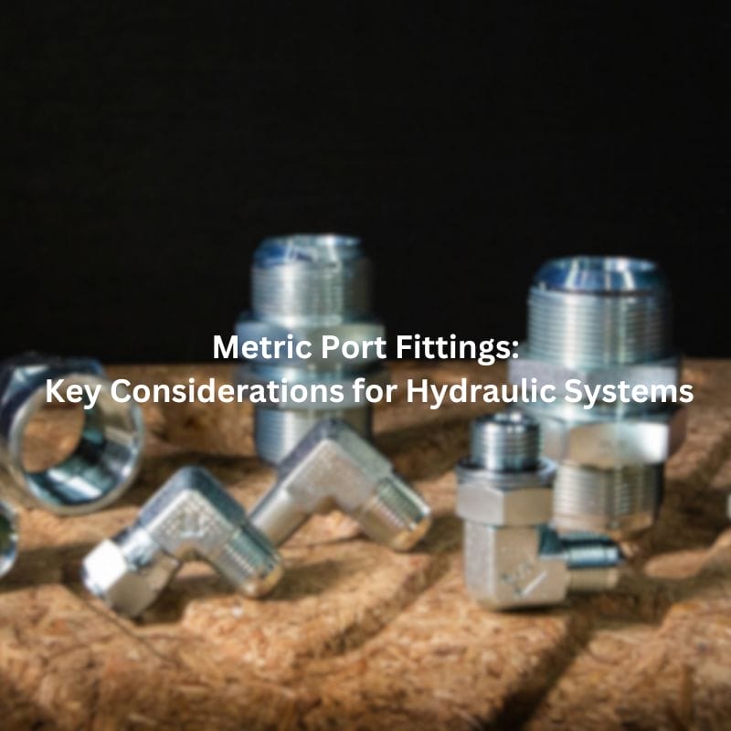
Metric Port Fittings Key Considerations for Hydraulic Systems

Metric Port Fittings: Key Considerations for Hydraulic Systems

Metric Port Fittings: Key Considerations for Hydraulic Systems

Introduction

Selecting the proper fitting for hydraulic systems is crucial to ensure efficient and leak-free operations. Incorrect fittings can lead to system failures, leaks, and costly downtime. Understanding the different types of metric ports is essential for making informed choices. The most common metric ports used in hydraulic systems are DIN (Deutsches Institut für Normung), BSPP (British Standard Pipe Parallel), and ISO 6149. Each type has its specifications, applications, and compatibility requirements, which must be considered to maintain the integrity and performance of the hydraulic system.

Types of Metric Ports

DIN Ports

DIN (Deutsches Institut für Normung) ports are standardized in Germany and widely utilized across numerous industrial applications due to their robustness and versatility. These ports are specifically designed to handle high-pressure environments, making them an ideal choice for sectors where durability and reliability are paramount. Commonly found in manufacturing, automotive, and heavy machinery industries, DIN ports are engineered to meet stringent performance criteria, which is why they are often seen in hydraulic systems that demand high precision and robustness.

DIN ports feature a 24-degree cone angle, providing a secure and leak-proof connection when paired with the appropriate fittings. This design not only enhances the reliability of the hydraulic system but also ensures that the connections remain stable even under extreme pressures. Their widespread use in critical applications underscores their importance in maintaining the efficiency and safety of hydraulic systems.

Compatibility with Specific Fittings

The success of DIN ports in hydraulic systems largely depends on their compatibility with specific fittings that adhere to the same DIN standards. Fittings designed for DIN ports are characterized by their 24-degree cone angle, which matches the port design to create a secure and leak-proof connection. This compatibility is crucial for ensuring the integrity of the hydraulic system, as mismatched fittings can lead to leaks, pressure drops, and potential system failures.

When selecting fittings for DIN ports, it is essential to verify that they conform to the same DIN standards. This ensures not only a proper fit but also optimal performance under the specified operating conditions. The use of standardized fittings simplifies maintenance and replacement processes, as components from different manufacturers that meet the DIN standards can be interchangeably used without compromising the system’s performance.

DIN 2353

ISO 6149 Ports

ISO 6149 ports are internationally standardized and widely recognized for their high performance and reliability in hydraulic systems. These ports are designed to meet stringent international standards, making them suitable for a variety of demanding applications, including mining, oil and gas, and industrial machinery. The ISO 6149 standard ensures that the ports and fittings are compatible and can withstand high pressures and harsh operating conditions.

The robust design of ISO 6149 ports makes them an excellent choice for heavy-duty applications where reliability and performance are paramount. These ports are engineered to provide a secure and leak-proof connection, even under extreme pressures, making them ideal for use in critical hydraulic systems that operate in challenging environments.

Compatible Fittings and Benefits

Fittings compatible with ISO 6149 ports are designed to provide superior leak resistance and durability. These fittings typically feature an O-ring seal, which forms a tight and reliable seal with the port, preventing fluid leakage and ensuring the integrity of the hydraulic system. The use of O-rings also simplifies the installation process, as the fittings can be easily screwed into place without requiring excessive torque.

The benefits of using ISO 6149 fittings include their ability to withstand high pressures and harsh operating conditions. This makes them suitable for demanding applications where performance and reliability are critical. The standardized design of ISO 6149 ports and fittings ensures compatibility across different manufacturers, allowing for easy replacement and maintenance without compromising the system’s performance.

Identifying the Correct Fitting

Thread Identification

Techniques for Identifying Thread Types

Identifying the correct thread type is crucial for ensuring a proper fit in hydraulic systems. Proper thread identification techniques include:

Measuring the Thread Pitch:

Thread pitch refers to the distance between adjacent threads. It is typically measured in millimeters for metric threads. Using a thread pitch gauge, which has multiple blades of different pitches, can help identify the correct pitch by matching the blade that fits the threads without gaps.

Measuring the Thread Diameter:

The thread diameter is the outer diameter of the thread, also known as the major diameter. This can be measured using a caliper. Ensuring accurate measurement is vital, as slight variations can lead to mismatched fittings.

Using Thread Gauges:

Thread gauges come in various sizes and are used to match the internal and external threads of the fittings and ports. These gauges help verify the size and type of the threads, ensuring compatibility.

Comparing to Standards:

Cross-referencing the measurements with standard charts (like ISO, DIN, or BSPP standards) helps in identifying the correct thread type. These charts provide detailed specifications for different thread types, aiding in accurate identification.

Importance of Accurate Measurement

Accurate measurement of threads is fundamental to the correct selection of fittings, preventing issues such as cross-threading, leaks, and system failures. Here’s why precision is essential:

Preventing Leaks:

Incorrect thread identification can lead to poor fitting connections, resulting in leaks. Leaks not only reduce system efficiency but can also lead to contamination and potential environmental hazards.

Avoiding Cross-Threading:

Cross-threading occurs when threads do not match correctly, causing damage to both the fitting and the port. This can lead to costly repairs and system downtime.

Ensuring System Integrity:

Properly identified and matched threads maintain the integrity of the hydraulic system, ensuring consistent pressure and performance. Accurate measurements guarantee that the fittings will handle the system’s operational requirements without failure.

Sealing Methods

Different Sealing Techniques

Sealing methods are essential for maintaining the integrity of hydraulic systems and preventing fluid leaks. The two most common sealing techniques are:

O-ring Seals:

O-rings are circular elastomer seals that fit into a groove and compress between the fitting and port, creating a seal. They are widely used due to their reliability and ease of installation.

Bonded Seals (Dowty Seals):

Bonded seals consist of a metal washer with a vulcanized rubber sealing ring bonded to the inside. They provide a high-pressure seal by compressing the rubber element when the fitting is tightened.

Metric Sealing Methods

Pros and Cons of Each Method

O-ring Seals:

Pros:

Reusable: O-rings can be reused multiple times if they are not damaged, making them cost-effective.

Easy to Replace: O-rings are simple to replace, which is advantageous during maintenance.

Versatile: Available in various materials (e.g., nitrile, Viton), O-rings can be selected based on the system’s operating conditions.

Cons:

Degradation Over Time: O-rings can degrade due to environmental factors such as temperature, chemical exposure, and aging.

Requires Proper Groove Design: The groove must be correctly designed to ensure effective sealing and avoid extrusion under pressure.

Bonded Seals:

Pros:

High-Pressure Resistance: Bonded seals are excellent for high-pressure applications due to the robust sealing provided by the metal-to-rubber bond.

Durable: The metal washer provides structural integrity, protecting the rubber seal from damage.

Cons:

Single-Use: Bonded seals are typically single-use, as the rubber element can be compressed permanently after the initial installation.

Harder to Replace: Replacing bonded seals can be more challenging compared to O-rings, requiring more effort and potentially higher costs.

Selection Guidelines

Compatibility Considerations

Ensuring Fitting and Port Match

Ensuring that the fitting matches the port type is crucial for preventing leaks and maintaining system efficiency. A mismatch between the fitting and port can lead to several issues, including inadequate sealing, cross-threading, and compromised system integrity. To avoid these problems, follow these steps:

Cross-Referencing Standards:

Utilize industry standards such as ISO, DIN, and BSPP to verify the compatibility of fittings and ports. These standards provide detailed specifications that can help ensure a proper match.

Manufacturers often provide compatibility charts or technical documents that specify which fittings are suitable for their ports.

Using Compatible Components:

Always use components from reputable manufacturers that adhere to industry standards. This practice reduces the risk of incompatibility and ensures high-quality connections.

If components from different manufacturers are being used, ensure they are cross-referenced for compatibility.

Avoiding Cross-Threading and Leaks

Proper alignment and careful installation are key to avoiding cross-threading, which can damage both the port and the fitting, leading to leaks. To achieve a leak-free and secure connection:

Correct Alignment:

Ensure that the threads of the fitting and port are aligned correctly before tightening. Misalignment can cause cross-threading, which damages the threads and creates potential leak points.

Hand-tighten the fitting initially to confirm proper alignment. Once aligned, use the appropriate tool to achieve the final torque.

Material and Coating Selection

Material Choices

The choice of material impacts the durability and performance of fittings. Common materials include:

Steel:

High strength, making it suitable for high-pressure applications.

Cost-effective compared to other materials.

Often used in general industrial and hydraulic applications where high pressure is a factor.

Stainless Steel:

Offers excellent corrosion resistance, making it ideal for harsh environments, including marine and chemical applications.

Higher cost but provides superior durability and longevity.

Suitable for sanitary and high-purity applications due to its resistance to contamination and easy cleaning.

Brass:

Good corrosion resistance, suitable for medium-pressure applications.

Easier to machine, making it a preferred material for complex fittings.

Commonly used in plumbing, gas applications, and systems requiring moderate pressure and corrosion resistance.

Importance of Corrosion Resistance and Durability

Corrosion resistance is vital for extending the lifespan of fittings, especially in harsh environments where exposure to chemicals, moisture, or saltwater is prevalent. The right material and coating can significantly enhance the longevity and reliability of the system:

Material Selection:

Choose materials that inherently resist corrosion, such as stainless steel, for applications exposed to harsh environments.

For cost-sensitive projects, coated steel can provide a balance between durability and affordability.

Coating Options:

Zinc plating or galvanization can enhance the corrosion resistance of steel fittings, making them suitable for less severe environments.

Nickel or chrome plating offers superior corrosion protection and is often used in more demanding applications.

Pressure and Temperature Ratings

Matching Fittings to System Specifications

Ensuring that fittings can withstand the system’s pressure and temperature requirements is essential for safety and performance. Properly matched fittings prevent failures and ensure reliable operation:

Consulting Manufacturer Specifications:

Always check the manufacturer’s specifications for pressure and temperature ratings of the fittings. These ratings are typically provided in technical datasheets or catalogs.

Ensure that the selected fittings can handle the maximum pressure and temperature conditions of the hydraulic system.

Understanding System Requirements:

Assess the operational conditions of the system, including normal and peak pressures and temperatures. Select fittings that can consistently perform under these conditions.

Safety Margins and Performance Requirements

Incorporating safety margins in the selection process ensures that fittings operate reliably under varying conditions, reducing the risk of failure. Consider these factors:

Safety Margins:

Choose fittings with pressure and temperature ratings higher than the maximum operating conditions of the system. This margin provides a buffer against unexpected spikes and ensures long-term reliability.

Common practice is to select fittings rated for at least 1.5 times the system’s maximum pressure.

Performance Requirements:

Evaluate the dynamic and static conditions of the hydraulic system. Dynamic conditions involve varying pressures and temperatures, while static conditions involve constant pressures and temperatures.

Ensure fittings can handle both types of conditions without compromising performance or safety.

Common Challenges and Solutions

Leak Prevention

Common Causes of Leaks

Leaks in hydraulic systems can arise from several factors, each of which needs to be carefully managed to maintain system integrity. The most common causes of leaks include:

Improper Fitting Selection:

Using the wrong type of fitting for the specific port can result in poor sealing and leaks. This often happens when fittings are not cross-referenced with the appropriate standards, leading to mismatches.

Incorrect Installation:

Incorrectly installed fittings, such as those that are over-tightened or under-tightened, can lead to leaks. Over-tightening can damage threads and seals, while under-tightening can leave connections too loose to maintain a proper seal.

Wear and Tear:

Over time, seals and fittings can degrade due to wear and tear, leading to leaks. This is particularly common in systems that operate under high pressure or in harsh environments.

Poor Quality Components:

Using low-quality fittings and seals can compromise the integrity of the hydraulic system. These components may not meet the necessary standards for pressure and temperature, leading to premature failure.

Leaks in Hydraulic Ports

Troubleshooting and Rectification Techniques

Effective troubleshooting and rectification techniques are essential for maintaining system performance and preventing leaks from escalating into more significant issues:

Inspecting Connections:

Regularly inspect all connections in the hydraulic system to identify any signs of leaks. Look for drips, wet spots, or discoloration around fittings and seals.

Use a UV dye and black light to detect leaks that might not be visible to the naked eye.

Replacing Worn Seals:

Replace seals that show signs of wear, such as cracks, hardening, or deformation. O-rings and bonded seals should be checked regularly and replaced as part of a preventive maintenance schedule.

Ensuring Proper Torque Application:

Follow manufacturer recommendations for the correct torque values during installation. Use a calibrated torque wrench to ensure that fittings are neither over-tightened nor under-tightened.

Avoid using pipe wrenches or other non-calibrated tools that can easily apply excessive force.

Using Thread Sealants and Lubricants:

Apply appropriate thread sealants or lubricants to ensure a better seal and facilitate easier installation. Ensure that the sealant is compatible with the hydraulic fluid and the materials of the fittings and ports.

Compatibility Issues

Addressing Mismatched Fittings and Ports

Mismatched fittings and ports are a common source of leaks and inefficiencies in hydraulic systems. Ensuring compatibility through proper selection and cross-referencing standards can prevent these issues:

Cross-Referencing Standards:

Verify that the fittings and ports conform to the same standards (e.g., DIN, ISO, BSPP). Cross-reference the specifications provided by manufacturers to ensure compatibility.

Utilize standardized charts and tools to match threads accurately.

Ensuring Proper Fit:

Double-check measurements such as thread pitch, diameter, and angle to ensure that fittings will match the ports correctly.

Conduct a dry fit before the final installation to ensure that components align correctly without forcing.

Solutions for Hybrid Systems with Mixed Fittings

Hybrid systems with mixed fittings require careful management to ensure compatibility and prevent leaks. Using adapters and ensuring proper sealing can help in managing these systems effectively:

Using Adapters:

Employ adapters that are designed to bridge different fitting types and standards. Ensure that the adapters are of high quality and compatible with the system’s pressure and temperature requirements.

Verify that adapters provide a secure and leak-proof connection between different types of fittings.

Ensuring Proper Sealing:

Use appropriate sealing methods, such as O-rings or bonded seals, to ensure that connections remain leak-proof even when different fitting types are used.

Check for compatibility of sealing materials with the hydraulic fluid and the environmental conditions of the system.

Regular Maintenance and Inspection:

Implement a regular maintenance schedule to inspect and replace worn or incompatible components in hybrid systems. This proactive approach can prevent leaks and system failures.

Train personnel to recognize and address compatibility issues promptly, ensuring that they understand the importance of maintaining a secure and efficient hydraulic system.

Conclusion

Selecting the right metric port fittings is crucial for the performance, safety, and longevity of hydraulic systems. Understanding the different types of metric ports, identifying the correct fittings, and following best practices for installation and maintenance are essential for achieving optimal results. The correct fitting selection ensures a secure, leak-free connection, maintaining system pressure and performance. Proper selection also helps in preventing system failures and reducing maintenance costs.

FAQ

Metric fittings are used to connect various components within hydraulic systems, ensuring secure, leak-proof connections that maintain system pressure and efficiency.

To identify the correct thread type, measure the thread pitch and diameter using a thread gauge or caliper, and compare these measurements with standard charts (e.g., ISO, DIN, BSPP).

The main types of metric ports include DIN ports, BSPP (British Standard Pipe Parallel) ports, and ISO 6149 ports, each designed for specific applications and standards.

Accurate measurement ensures the correct selection of fittings, preventing issues such as leaks and cross-threading, which can damage components and compromise system integrity.

O-ring seals provide a reliable and reusable seal, are easy to replace, and are available in various materials to suit different operating conditions.

To prevent leaks, ensure proper fitting and port compatibility, follow correct installation procedures (including proper torque application), regularly inspect connections, and replace worn seals promptly.

Metric Compression Fittings Everything You Need to Know

Metric Compression Fittings: Everything You Need to Know

Metric Compression Fittings: Everything You Need to Know

Introduction

Metric Compression Fittings are critical components used to create secure, leak-proof connections in various piping and tubing systems. These fittings are designed to withstand high pressure and temperature, making them indispensable in industries such as hydraulics, pneumatics, automotive, plumbing, HVAC, aerospace, and defense. This post aims to provide a comprehensive understanding of metric compression hydraulic fittings, covering their definition, advantages, applications, working principles, and selection criteria. By exploring these aspects, we aim to equip you with the knowledge needed to make informed decisions when choosing and using Metric compression hydraulic fittings in your projects.

What Are Metric Compression Hydraulic Fittings?

Metric compression hydraulic fittings are specialized connectors used to join sections of tubing or piping securely and without leakage. They are commonly utilized in various applications where maintaining the integrity of fluid or gas systems is crucial. The primary components of a metric compression fitting include a compression nut, a compression ring (or ferrule), and a fitting body. When the nut is tightened, it compresses the ring onto the tubing, creating a tight, secure seal that prevents leaks.

Metric Compression hydraulic fitting

Types

Metric compression hydraulic fittings come in two main types: single ferrule and double ferrule.

Single Ferrule

Single ferrule fittings use one compression ring to create a seal between the tubing and the fitting body. The single ferrule design is simple and effective, providing a strong grip and seal with fewer components. These fittings are often chosen for applications where ease of installation and cost-effectiveness are priorities. They are widely used in various industries due to their reliability and straightforward design.

Double Ferrule

Double ferrule fittings feature two compression rings: a front ferrule and a back ferrule. The front ferrule creates a seal on the tubing surface while the back ferrule provides additional support and grip, enhancing the fitting’s overall performance. This design ensures a more secure connection and is particularly useful in high-pressure and high-vibration environments. Double ferrule fittings are known for their superior sealing capabilities and resistance to mechanical stress, making them ideal for critical applications.

Common Materials Used

Metric compression fittings are manufactured from various materials, each chosen for its specific properties and suitability for different applications. The most common materials include:

Stainless Steel: Known for its excellent corrosion resistance, strength, and durability, stainless steel is often used in harsh environments and applications requiring high levels of hygiene, such as in food processing, pharmaceutical, and chemical industries.

Brass: Brass fittings are popular for their good corrosion resistance, machinability, and thermal conductivity. They are widely used in plumbing, HVAC, and automotive applications due to their cost-effectiveness and reliability.

Other Materials: Depending on the specific requirements, Metric compression hydraulic fittings can also be made from other materials like plastic, copper, and various alloys. Each material offers unique advantages in terms of performance, cost, and suitability for different operating conditions.

Advantages

Leak-Proof Connections

One of the most significant advantages of Metric hydraulic compression fittings is their ability to create leak-proof connections. The compression mechanism ensures a tight seal between the fitting and the tubing, preventing any fluid or gas from escaping. This feature is critical in applications where even a minor leak can lead to significant safety hazards or operational inefficiencies.

High Pressure and Temperature Tolerance

Metric compression hydraulic fittings are designed to withstand high pressures and temperatures, making them suitable for demanding environments. They are constructed from robust materials like stainless steel and brass, which can endure extreme conditions without compromising performance. This high tolerance makes them ideal for applications in hydraulic systems, where pressures can be exceptionally high, and in environments with significant temperature variations, such as automotive or industrial processes.

Easy Installation and Maintenance

Another notable advantage of Metric compression hydraulic fittings is their ease of installation and maintenance. Unlike welded or soldered joints, compression fittings do not require specialized tools or equipment for installation. They can be quickly assembled using basic tools, which simplifies the installation process and reduces labor costs. Additionally, their design allows for easy disassembly and reassembly, facilitating straightforward maintenance and replacement without the need for complex procedures or significant downtime.

Applications

Hydraulic Systems

In hydraulic systems, where fluid power is used to perform various functions, maintaining high-pressure integrity is vital. Metric compression hydraulic fittings are commonly used to connect hydraulic lines and components, ensuring that the hydraulic fluid remains contained within the system. Their ability to withstand high pressures and prevent leaks makes them indispensable in heavy machinery, construction equipment, and industrial automation systems.

Automotive Applications

In the automotive industry, Metric compression hydraulic fittings are used in various systems, including fuel lines, brake systems, and air conditioning units. Their robust construction and ability to withstand high pressures and temperatures make them suitable for the demanding conditions encountered in vehicles. The fittings ensure that fluids, such as fuel and brake fluid, are securely transported without leaks, contributing to the overall safety and performance of the vehicle.

Plumbing and HVAC Systems

Metric compression hydraulic fittings are also extensively used in plumbing and HVAC (Heating, Ventilation, and Air Conditioning) systems. In plumbing, they provide secure connections for water supply lines, ensuring leak-free performance in residential, commercial, and industrial settings. In HVAC systems, these fittings are used to connect refrigerant lines, ensuring the efficient transfer of cooling or heating fluids. Their versatility and ease of installation make them a preferred choice for contractors and engineers in these applications.

Choosing the Right Metric Compression Fitting

Selecting the appropriate metric compression fitting for your application is crucial to ensure system integrity, safety, and performance. Several key factors must be taken into account during the selection process:

Material Compatibility

The material of the compression fitting must be compatible with the fluid or gas it will be in contact with and the operating environment. For example, stainless steel is often chosen for its excellent corrosion resistance, making it ideal for harsh environments and applications requiring high levels of hygiene, such as food processing and pharmaceuticals. Brass is favored for its good corrosion resistance, machinability, and thermal conductivity, making it suitable for plumbing, HVAC, and automotive applications. Choosing the wrong material can lead to premature failure, corrosion, or chemical reactions that compromise the system’s integrity.

Pressure and Temperature Ratings

It is essential to choose fittings that can withstand the maximum pressure and temperature conditions of your application. Each fitting comes with specified pressure and temperature ratings, which indicate the limits within which the fitting can operate safely. Exceeding these limits can lead to leaks, bursts, or other catastrophic failures. Therefore, always ensure that the selected fitting meets or exceeds the required specifications for your system’s operating conditions.

Metric Compression ferrule Fittings

Sizing and Thread Type

Proper sizing is crucial for ensuring a secure and leak-free connection. Metric compression hydraulic fittings are available in various sizes, and selecting the correct size involves matching the fitting to the outside diameter of the tubing. Additionally, the thread type and pitch must be compatible with the mating components. Mismatched threads can lead to improper sealing, leaks, and mechanical failure. Always verify the thread type (e.g., parallel or tapered) and ensure it matches the mating parts.

Common Standards and Specifications

Metric compression hydraulic fittings are manufactured according to various standards and specifications to ensure compatibility and performance. Understanding these standards can help you select the right fittings for your application:

DIN (Deutsches Institut für Normung)

DIN standards are widely recognized and used in many industries worldwide. They cover various aspects of compression fittings, including dimensions, materials, and performance requirements. DIN-compliant fittings ensure high quality and compatibility with other DIN-standard components, making them a reliable choice for many applications.

ISO (International Organization for Standardization)

ISO standards provide internationally recognized guidelines for the design, manufacturing, and testing of compression fittings. ISO-compliant fittings are designed to meet stringent global standards, ensuring consistency, reliability, and interoperability across different regions and industries. Choosing ISO-compliant fittings can simplify sourcing and ensure compatibility with other ISO-standard components.

EN (European Norm)

EN standards are specific to the European Union and cover a wide range of industrial products, including compression fittings. EN standards ensure that fittings meet the necessary safety, quality, and performance criteria required in the European market. Using EN-compliant fittings can facilitate compliance with regional regulations and ensure high-quality performance.

Metric vs. Imperial Compression Fittings

Key Differences in Sizing and Standards

Metric and imperial compression fittings differ primarily in their sizing conventions and the standards they adhere to. Metric fittings are measured using the metric system, which uses millimeters (mm) as the unit of measurement for tubing outer diameters (OD). In contrast, imperial fittings use the imperial system, measuring tubing OD in inches.

Sizing

Metric Fittings: Sizes are expressed in millimeters (e.g., 6mm, 8mm, 10mm). This provides a more precise measurement system, particularly advantageous in applications requiring exact dimensions and tight tolerances.

Imperial Fittings: Sizes are expressed in fractions of an inch (e.g., 1/4″, 1/2″, 3/4″). The imperial system, while still widely used in certain regions and industries, offers less precision compared to the metric system.

Standards

Metric Standards: Adherence to standards such as DIN (Deutsches Institut für Normung), ISO (International Organization for Standardization), and EN (European Norm) ensure consistency, quality, and compatibility across a wide range of applications and regions.

Imperial Standards: These fittings typically adhere to standards set by organizations like SAE (Society of Automotive Engineers) and ASTM (American Society for Testing and Materials). While these standards are robust, they are primarily used in regions where the imperial system is predominant, such as the United States.

3420 BSPP Hydraulic Fittings drawing

Advantages of Metric Fittings Over Imperial

Precision and Compatibility

Metric fittings offer greater precision due to their smaller unit measurements. This precision is crucial in applications requiring tight tolerances and exact dimensions, such as in high-performance hydraulic and pneumatic systems.

The widespread international adoption of the metric system facilitates easier sourcing and compatibility across different regions and industries, reducing the risk of mismatched components and improving supply chain efficiency.

Ease of Conversion and Standardization

The metric system’s simplicity, based on multiples of ten, makes calculations and conversions more straightforward compared to the imperial system, which uses fractions and different base units. This ease of use simplifies engineering design, manufacturing processes, and inventory management.

Global standardization around the metric system allows for more consistent manufacturing practices and quality control, ensuring that metric fittings meet stringent international standards and perform reliably in diverse applications.

Situations Where Imperial Fittings Might Be Preferred

Regional Preferences and Legacy Systems

In regions where the imperial system is still predominant, such as the United States, imperial fittings may be preferred due to existing infrastructure and legacy systems. Many industries and applications in these regions have long histories of using imperial measurements and switching to metric fittings might require significant changes to existing processes and equipment.

Maintenance and replacement parts for older systems designed with imperial fittings will often necessitate the continued use of imperial fittings to ensure compatibility.

Industry-Specific Requirements

Certain industries, particularly in North America, have specific standards and practices built around the imperial system. For example, the aerospace and automotive industries in the United States often use imperial fittings to comply with local standards and regulations.

In applications where equipment and components are primarily sourced from imperial-standard suppliers, maintaining consistency with imperial fittings can simplify procurement and reduce the risk of compatibility issues.

In summary, while Metric compression hydraulic fittings offer advantages in terms of precision, global compatibility, and ease of use, imperial fittings may still be preferred in regions with established legacy systems, industry-specific requirements, and user familiarity. Understanding the key differences and advantages of each system can help you make informed decisions when selecting the appropriate fittings for your specific applications.

Conclusion

In summary, Metric compression hydraulic fittings are essential components known for their precision, reliability, and versatility across various industries. They offer leak-proof connections, withstand high pressures and temperatures, and are easy to install and maintain. Understanding the differences between metric and imperial fittings, along with the importance of choosing the right materials and adhering to standards, ensures optimal performance in any application. For further information or to find the right fittings for your needs, consider contacting Topa.

FAQ

Metric compression hydraulic fittings are connectors used to join sections of tubing or piping securely, creating leak-proof connections in various fluid and gas systems.

Common materials include stainless steel, brass, and sometimes plastic or copper, each chosen based on the specific application requirements such as corrosion resistance and strength.

They provide leak-proof connections, high pressure and temperature tolerance, easy installation and maintenance, and versatility across different applications.

Consider factors such as material compatibility, pressure and temperature ratings, sizing, thread type, and adherence to relevant standards like DIN, ISO, and EN.

These fittings are used in hydraulic and pneumatic systems, automotive applications, plumbing, HVAC, aerospace, and defense industries.

Single ferrule fittings use one compression ring to seal the connection, while double ferrule fittings use two rings for enhanced sealing and grip, offering better performance in high-pressure and high-vibration environments.

Contact Topa

Have a question or suggestion? Fill out the form below to get in touch with one of our experts.

Metric Bite Type Fittings A Comprehensive Guide

Metric Bite Type Fittings: A Comprehensive Guide

Metric Bite Type Fittings: A Comprehensive Guide

Introduction

Metric bite type fittings are essential components in fluid and gas systems, renowned for their reliability and versatility. These fittings provide a secure and leak-proof connection, making them indispensable in industries such as hydraulics, pneumatics, automotive, and more. This guide delves into the different types of metric bite type fittings, their specific applications, and the best practices for their selection, installation, and maintenance. By understanding these aspects, professionals can make informed decisions that enhance the efficiency and safety of their systems.

Understanding Metric Bite Type Fittings

Definition and Basic Concept

Metric bite type fittings are mechanical connectors designed to join sections of tubing in a secure and leak-proof manner. The term “bite type” refers to the way the fitting interacts with the tube. When the nut of the fitting is tightened, the ferrule (a ring-like component within the fitting) bites into the outer surface of the tube. This action creates a strong mechanical grip and a gas-tight or liquid-tight seal. These fittings are often used in high-pressure applications due to their ability to maintain integrity under stress.

The basic concept behind metric bite type fittings revolves around their ability to provide a reliable and efficient connection without the need for welding or soldering. This makes them particularly advantageous in applications where disassembly and reassembly are required, or where heat-sensitive materials are involved. The metric specification indicates that the dimensions and tolerances of these fittings adhere to the metric system, which is widely used in international applications and industries.

4C Bite Type Tube Plug Topa

History and Development

The history of metric bite type fittings dates back to the mid-20th century when the need for reliable and easy-to-install connections in hydraulic and pneumatic systems became increasingly apparent. Early versions of these fittings were developed to address the limitations of traditional threaded and welded connections, which often required specialized skills and tools.

The development of bite type fittings was driven by the demands of industries such as aerospace, automotive, and manufacturing, where high-pressure systems are common. Engineers sought a solution that could offer both reliability and ease of use. The introduction of the ferrule-based design marked a significant advancement, providing a secure grip on the tubing without compromising the flow of fluids or gases.

Over the years, advancements in materials science and manufacturing techniques have further refined the design and performance of metric bite type fittings. Modern fittings are made from a variety of materials, including stainless steel, brass, and carbon steel, each selected for their specific properties and suitability for different applications. Innovations such as improved ferrule designs and enhanced sealing technologies have continued to enhance the performance and reliability of these fittings.

Key Features and Benefits

Metric bite type fittings offer several key features and benefits that make them a preferred choice in many applications:

Leak-Proof Seal: The biting action of the ferrule creates a tight seal that prevents leaks, even under high pressure. This ensures the integrity of the fluid or gas system, reducing the risk of contamination and loss of efficiency.

High Pressure and Temperature Tolerance: These fittings are designed to withstand extreme conditions, making them suitable for use in demanding environments such as hydraulic systems, automotive applications, and industrial machinery.

Ease of Installation: Unlike welded or soldered connections, metric bite type fittings can be installed quickly and easily with standard tools. This reduces installation time and costs, making them an attractive option for both initial installations and maintenance.

Versatility: Available in a wide range of sizes and configurations, metric bite type fittings can be used in various applications. They are compatible with different types of tubing materials, including metal and plastic.

Standardization: Adhering to metric standards ensures compatibility and interchangeability with other components, simplifying the design and maintenance of fluid and gas systems.

Types of Metric Bite Type Fittings

Metric bite type fittings come in various configurations to meet the diverse needs of fluid and gas systems. These fittings are engineered to provide reliable and leak-proof connections in a range of applications, from industrial machinery to automotive systems. The primary types of metric bite type fittings include male fittings, female fittings, elbow fittings, tee fittings, and cross fittings. Additionally, these fittings are available in different materials, such as stainless steel and brass, to suit specific requirements and environments.

Male Fittings

Male fittings, also known as male connectors, feature external threads that allow them to be screwed into female fittings or ports. These fittings are commonly used to connect tubing to other components in a system, such as valves, pumps, and cylinders. The external threading ensures a secure and tight connection, preventing leaks and maintaining system integrity.

Female Fittings

Female fittings, or female connectors, have internal threads that receive the external threads of male fittings. These fittings are designed to connect tubing to male-threaded components, creating a seamless and reliable connection. Female fittings are widely used in systems where quick disassembly and reassembly are required, as they provide a straightforward and secure method for joining components.

Elbow Fittings

Elbow fittings are designed to change the direction of tubing in a fluid or gas system. These fittings are available in different angles, most commonly 45 degrees and 90 degrees, allowing for precise routing of tubing around obstacles and within confined spaces. Elbow fittings are essential in applications where space constraints or specific flow directions must be accommodated. They are available in both male and female configurations, as well as in various sizes and materials.

Metric Bite Type Fittings type

Tee Fittings

Tee fittings, or tee connectors, facilitate three-way connections in a fluid or gas system. These fittings have one inlet and two outlets (or vice versa), forming a T-shaped intersection. Tee fittings are commonly used to split or combine fluid or gas flow in a system, making them ideal for applications requiring distribution to multiple points. They are available in equal and reduced configurations, allowing for different flow rates and tube sizes to be connected.

Cross Fittings

Cross fittings, also known as four-way fittings, enable four-way connections in a fluid or gas system. These fittings have one inlet and three outlets (or vice versa), forming a cross-shaped intersection. Cross fittings are used in applications where fluid or gas needs to be distributed to multiple branches from a single source. They are less common than tee fittings but are essential in complex systems that require multiple flow paths.

Material Variations

Metric bite type fittings are manufactured from a variety of materials to meet the demands of different applications and environments. The most common materials include:

Stainless Steel: Known for its corrosion resistance, strength, and durability, stainless steel fittings are ideal for harsh environments, such as marine and chemical processing applications.

Brass: Brass fittings offer excellent machinability, corrosion resistance, and conductivity, making them suitable for applications in plumbing, refrigeration, and low-pressure hydraulic systems.

Carbon Steel: Carbon steel fittings provide high strength and durability, making them suitable for high-pressure and heavy-duty applications, such as industrial machinery and automotive systems.

Applications of Metric Bite Type Fittings

Hydraulic Systems

In hydraulic systems, metric bite type fittings are crucial for maintaining the integrity and efficiency of fluid power systems. These fittings connect hydraulic hoses, tubes, and components, ensuring that high-pressure fluids are transferred safely and reliably. Common applications include:

Construction Equipment: Hydraulic excavators, bulldozers, and loaders rely on these fittings for the operation of hydraulic cylinders and motors.

Manufacturing Machinery: Presses, injection molding machines, and CNC machines use hydraulic systems with metric bite type fittings for precise control and movement.

Automotive Industry

The automotive industry extensively uses metric bite type fittings in various systems where durability and leak-proof connections are critical. These fittings are found in:

Fuel Lines: Ensuring secure and leak-free connections in fuel delivery systems.

Brake Systems: Providing reliable connections in hydraulic brake lines, crucial for vehicle safety.

Transmission Cooling Systems: Used in cooling lines to maintain optimal transmission temperatures.

Plumbing Systems

In plumbing systems, these fittings are used to connect pipes and tubes, ensuring a leak-proof seal that is vital for water distribution and waste management. Applications include:

Residential Plumbing: Connecting water supply lines to faucets, toilets, and showers.

Commercial Buildings: Ensuring reliable connections in water distribution systems for offices, hotels, and restaurants.

Irrigation Systems: Providing secure connections in garden and agricultural irrigation systems.

How Metric Bite Type Fittings Work

Metric bite type fittings function through a unique biting mechanism that creates a strong and leak-proof connection between tubing and the fitting itself. The core components of a metric bite type fitting include the body, nut, and ferrule (or cutting ring). Here’s a step-by-step breakdown of how they work:

Insertion: The tube is inserted into the fitting body until it reaches a defined stop. This ensures the tube is properly aligned within the fitting.

Tightening the Nut: When the nut is tightened, it forces the ferrule to move axially along the tube. As the ferrule advances, it starts to bite into the outer surface of the tube.

Biting Action: The ferrule’s sharp edge cuts into the tube, creating a secure grip. This biting action deforms the tube slightly, forming a tight, mechanical seal between the tube and the fitting body.

Sealing: The compression of the ferrule against the tube and fitting body forms a robust seal. This seal is capable of withstanding high pressures and prevents any leakage of fluids or gases.

The effectiveness of this mechanism relies on the precise engineering of the fitting components, ensuring that the ferrule bites uniformly into the tube and the seal remains intact even under fluctuating pressures and temperatures.

Assembly and Installation Process

Proper assembly and installation of metric bite type fittings are crucial for achieving a secure and leak-proof connection. Here is a step-by-step guide:

Preparation

Ensure that the tube end is cut squarely and is free from burrs. Use a tube cutter for a clean cut.

Clean the tube end to remove any debris, oil, or contaminants that might affect the sealing process.

Insertion

Insert the tube into the fitting body until it bottoms out against the internal shoulder of the fitting. This ensures that the tube is properly positioned for the biting action.

Initial Tightening:

Hand-tighten the nut onto the fitting body. This initial tightening aligns the tube and ferrule properly within the fitting.

Wrench Tightening:

Using a wrench, tighten the nut further according to the manufacturer’s specifications. Typically, this involves turning the nut a specific number of turns beyond hand-tight.

The common practice is to mark the position of the nut and then tighten it by an additional 1.5 to 2 turns for initial assembly, ensuring the ferrule bites securely into the tube.

Inspection

After tightening, inspect the connection to ensure there is no visible gap between the fitting body and the nut.

Check for any misalignment or improper seating of the tube within the fitting.

Maintenance Tips

Conduct Regular Inspections

Frequency: Schedule inspections at regular intervals based on the system’s operating conditions and manufacturer recommendations.

What to Look For: Check for signs of wear, corrosion, or damage on the fittings, tubing, and connected components.

Actions: If any wear or damage is detected, replace the affected components promptly to avoid system failure.

Clean the Fittings Periodically

Cleaning Frequency: Establish a routine cleaning schedule to maintain the fittings’ cleanliness and prevent contamination.

Cleaning Method: Use appropriate cleaning solutions and methods recommended by the manufacturer. Avoid abrasive materials that could damage the fittings.

Benefits: Regular cleaning prevents the buildup of dirt, debris, and contaminants that can compromise the seal and functionality of the fittings.

Apply Lubrication if Recommended by the Manufacturer

Lubrication Points: Identify the specific points on the fitting that require lubrication, such as the threads or ferrule.

Lubrication Type: Use the type of lubricant specified by the manufacturer to ensure compatibility and effectiveness.

Procedure: Apply the lubricant as directed during installation or maintenance to reduce friction and wear, and to ensure smooth assembly and disassembly.

Troubleshooting Common Issues

Leaks

Symptoms: The presence of fluid or gas escaping from the fitting connection.

Causes:

Improper installation (e.g., insufficient tightening or misalignment of the tube).

Worn or damaged components (e.g., ferrule, tube, or fitting body).

Solutions:

Check for proper installation by verifying the fitting is tightened according to manufacturer specifications.

Inspect the fitting and tubing for damage; replace any worn or damaged parts.

Reassemble the fitting, ensuring the tube is fully inserted and the nut is properly tightened.

Vibration

Symptoms: Excessive movement or noise from the fitting connection, potentially leading to leaks or component fatigue.

Causes:

Inadequately secured fittings.

High levels of vibration in the operating environment.

Solutions:

Ensure all fittings are securely tightened.

Consider using vibration-resistant fittings or supports to dampen the effects of vibration.

Implement additional supports or clamps to stabilize the tubing and fittings, reducing movement and the risk of fatigue.

Conclusion

In summary, metric bite type fittings are crucial for ensuring secure, leak-proof connections in fluid and gas systems across various industries. Their robust design, ease of installation, and versatility make them indispensable in applications ranging from hydraulics and pneumatics to automotive and HVAC systems. Regular maintenance and proper troubleshooting are essential to maximize their lifespan and efficiency. For tailored solutions and optimal performance, always seek professional advice to address specific needs and challenges in your systems.

FAQ

Metric bite type fittings are used to create secure, leak-proof connections in fluid and gas systems, commonly found in hydraulic, pneumatic, automotive, and HVAC applications.

The fittings themselves can often be reused if they are in good condition, but the ferrules typically should not be reused as they may not seal properly a second time.

Ensure the tube is cut squarely, deburred, and clean before insertion. Follow the manufacturer’s torque specifications when tightening the nut to create a proper seal.

Metric bite type fittings are commonly made from stainless steel, brass, and carbon steel, chosen based on the specific application’s pressure, temperature, and corrosion resistance requirements.

Regular inspections should be conducted at intervals recommended by the manufacturer or based on the system’s operating conditions, typically ranging from monthly to annually.

Check for proper installation and ensure the fitting is tightened according to specifications. If the leak persists, inspect for damage and replace any worn components as needed.

Metric Bolt Measurements A Comprehensive Size Guide

Metric Bolt Measurements: A Comprehensive Size Guide

Metric Bolt Measurements: A Comprehensive Size Guide

Table of Contents

Introduction

Accurate bolt measurements are crucial in various industries, from automotive and aerospace to construction and manufacturing. These measurements ensure the integrity and safety of mechanical assemblies, preventing failures that can lead to costly downtime or even catastrophic accidents. This guide aims to provide a comprehensive understanding of metric bolt measurements, offering detailed insights into the components, dimensions, grades, and measurement techniques essential for selecting and using bolts correctly.

Basics of Metric Bolt Measurements

What are Metric Bolts?

Metric bolts are a type of fastener that conform to the metric measurement system, which is the predominant standard used globally. Unlike imperial bolts, which are measured in inches, metric bolts are specified in millimeters, facilitating uniformity and compatibility in international projects. These bolts are available in a variety of sizes and grades, each tailored to meet specific application needs. The use of metric bolts ensures precision and standardization across diverse industries, making them essential components in engineering, manufacturing, and construction.

Why Accurate Measurements Matter

Accurate bolt measurements are essential for ensuring the integrity and safety of mechanical assemblies. Incorrect bolt dimensions can lead to improper fits, which may result in mechanical failures, structural weaknesses, or even catastrophic accidents. Precise measurements ensure that the bolts fit correctly, providing the necessary strength and stability. This is particularly crucial in industries where safety and reliability are paramount, such as aerospace, automotive, and construction.

Components of a Metric Bolt

Overall Length

Head

The head of a metric bolt is the top part that is usually shaped to accommodate a specific type of tool, such as a wrench or a screwdriver. Common head shapes include hexagonal, round, and flat. The head size and shape are important for the application as they determine the tool required for installation and the amount of torque that can be applied.

Shank

The shank is the unthreaded portion of the bolt that lies between the head and the thread. The length of the shank varies depending on the bolt’s intended use. It provides additional strength and helps in positioning the bolt correctly in the assembly.

Thread

The thread is the helical ridge that runs along the bolt’s length, starting from the shank to the end of the bolt. Threads are crucial for the bolt’s ability to screw into a nut or a threaded hole, providing the necessary clamping force to hold components together. The pitch of the thread, which is the distance between adjacent threads, is a critical measurement in ensuring compatibility with nuts and threaded holes.

Nut

The nut is a separate component that works with the bolt to fasten components together. It has an internal thread that matches the bolt’s external thread. The correct pairing of bolt and nut threads is vital for achieving the desired clamping force and ensuring the assembly’s stability.

Industries Using Metric Bolts

Industries Using Metric Bolts

Metric bolts are widely used across various industries due to their standardization and reliability. Some of the key industries include:

Automotive: In the automotive industry, metric bolts are used extensively in the assembly of vehicles. They are essential for fastening parts such as engines, chassis, and body panels, ensuring the vehicle’s structural integrity and performance.

Construction: Construction projects often rely on metric bolts for assembling structural components, machinery, and equipment. These bolts are crucial for maintaining the safety and stability of buildings, bridges, and other infrastructures.

Machinery: In the manufacturing and machinery industries, metric bolts are used to assemble equipment, tools, and machines. They provide the necessary strength and precision required for the proper functioning of mechanical systems.

Understanding Bolt Dimensions

Diameter

Nominal Diameter

The nominal diameter of a bolt refers to the diameter of the bolt’s shank, which is the part without the threads. This measurement is crucial as it determines the bolt’s size category and ensures that it fits correctly in pre-drilled holes or nuts. The nominal diameter is typically specified in millimeters for metric bolts.

How to Measure Diameter

To measure the diameter of a bolt accurately, you can use a caliper. Place the caliper’s jaws around the unthreaded part of the bolt and read the measurement. Ensure that the caliper is perpendicular to the bolt to avoid skewed readings. For threaded sections, measuring across the threads at their widest point will give you the major diameter.

Length

Overall Length vs. Grip Length

Overall Length: The overall length of a bolt is the total length from the flat part of the head to the tip of the bolt. This measurement is essential for determining how far the bolt will extend into the material or components it is fastening.

Grip Length: The grip length is the unthreaded portion of the bolt, which lies between the head and the start of the threads. This section bears the load and provides the clamping force required in the assembly. It is important to choose a bolt with an appropriate grip length to ensure a secure hold.

Tools for Measuring Bolt Length

To measure the length of a bolt, you can use a ruler or a caliper. For longer bolts, a ruler is sufficient. Place the bolt alongside the ruler, starting from the head to the tip, and note the measurement. For more precision, especially with shorter bolts, a caliper is preferred. Ensure that the bolt is straight when taking the measurement to avoid inaccuracies.

Measure Banjo bolt Thread

Thread Pitch

Thread pitch is the distance between adjacent threads on a bolt, measured parallel to the bolt’s axis. It is usually specified in millimeters for metric bolts. For example, a bolt with a thread pitch of 1.5 mm has 1.5 millimeters between each thread. The thread pitch is critical for ensuring compatibility between the bolt and the nut or threaded hole, as it affects the fit and the fastening strength.

Methods for Measuring Thread Pitch

To measure thread pitch, you can use a thread gauge or a caliper. A thread gauge consists of multiple blades, each marked with a different pitch. Simply match the bolt’s threads to the gauge’s blades until you find the one that fits perfectly. Alternatively, using a caliper, measure the distance between the peaks of two adjacent threads and note the measurement.

Head Size

Different Types of Bolt Heads

Bolts come with various head types, each designed for specific applications and tools. Common types include:

Hexagonal Head: Widely used for its ease of installation with a wrench or socket.

Round Head: Often used where a low-profile head is needed.

Flat Head: Designed to sit flush with the material surface, providing a smooth finish.

Socket Head: Used in applications requiring a recessed head, installed with an Allen wrench.

Measuring Head Dimensions

To measure the head dimensions, you need to consider both the diameter and the height of the head. Use a caliper to measure the diameter across the flats for hexagonal heads or the overall diameter for round heads. Measure the height from the base to the top of the head. These measurements are important for ensuring that the bolt head fits within the intended space and can be properly engaged by the appropriate tool.

Understanding these dimensions is crucial for selecting the right bolt for your application, ensuring proper fit, and achieving the desired mechanical performance. Accurate measurement techniques and tools are essential for maintaining the integrity and safety of your assemblies.

Metric Bolt Grades and Strength

Bolt Grades

Metric bolts come in various grades, each indicating the bolt’s strength and suitability for different applications. The grade of a bolt is determined by its material composition and the heat treatment it has undergone. Higher grade bolts are made from stronger materials and are subjected to more rigorous heat treatments, making them suitable for applications that require higher strength and durability. Common metric bolt grades include:

Grade 4.6: Typically used for light-duty applications. It has a tensile strength of 400 MPa and a yield strength of 240 MPa.

Grade 8.8: One of the most common grades, suitable for medium-duty applications. It has a tensile strength of 800 MPa and a yield strength of 640 MPa.

Grade 10.9: Used for high-strength applications, this grade offers a tensile strength of 1000 MPa and a yield strength of 900 MPa.

Grade 12.9: The highest common grade, used in the most demanding applications. It has a tensile strength of 1200 MPa and a yield strength of 1080 MPa.

Markings and Identification

Some metric bolts are marked with their grade on the head, which makes it easy to identify their strength and material composition. These markings usually consist of two numbers separated by a dot. The first number represents one-tenth of the nominal tensile strength in MPa, while the second number is the ratio of yield strength to tensile strength. For example, a Grade 8.8 bolt has a tensile strength of 800 MPa and a yield strength of 80% of that, or 640 MPa. Additionally, bolts may have other markings to indicate the manufacturer’s identification or other specific attributes.

Strength Specifications

Tensile Strength

Tensile strength is the maximum amount of tensile (pulling) stress that a bolt can withstand before failing. It is a critical parameter for determining the suitability of a bolt for a particular application. High tensile strength is required in applications where the bolt will be subjected to significant stretching forces.

Yield Strength

Yield strength is the amount of stress at which a bolt begins to deform plastically. Below this stress, the bolt will return to its original shape when the load is removed. Above this stress, the bolt will be permanently deformed. Yield strength is an important consideration in applications where the bolt will be subjected to constant or fluctuating loads, as it indicates the load level beyond which the bolt will not maintain its shape.

Proof Load

Proof load is the maximum stress that a bolt can withstand without any permanent deformation. It is a safety margin below the yield strength, ensuring that the bolt remains functional under the specified load. Proof load testing is typically performed to verify the bolt’s quality and performance in real-world conditions.

Choosing the Right Grade

Selecting the right bolt grade is crucial for ensuring the safety, reliability, and performance of the assembly. Here are some factors to consider:

Load Requirements: Determine the tensile and shear loads the bolt will be subjected to. Higher loads require bolts with higher tensile and yield strength.

Environmental Conditions: Consider the operating environment, such as exposure to moisture, chemicals, or extreme temperatures. Stainless steel or coated bolts may be necessary for corrosive environments.

Material Compatibility: Ensure the bolt material is compatible with the materials being fastened. This helps prevent galvanic corrosion and other material-related issues.

Safety Margins: Always choose a bolt grade that provides a sufficient safety margin beyond the maximum expected load to account for unexpected stresses and ensure long-term reliability.

Cost and Availability: While higher-grade bolts offer superior strength, they are also more expensive. Balance the cost with the application’s requirements to make an economical choice without compromising safety.

How to Custom Metric Bolt Fitting

Create the Blueprint

The first step in customizing a metric bolt fitting is to create a detailed blueprint. This involves drafting a technical drawing that outlines all the specifications of the bolt, including its dimensions, thread type, head shape, and any special features. Ensure that the blueprint adheres to industry standards and includes precise measurements and tolerances. Collaboration with engineers or designers might be necessary to ensure the blueprint meets the required functionality and compatibility with other components.

banjo Thread Size

Select the Dimensions

Once the blueprint is ready, the next step is to select the appropriate dimensions for your custom bolt. This includes:

Diameter: Choose the nominal diameter based on the load requirements and the size of the holes it will pass through.

Length: Determine the overall length, ensuring it provides the necessary clamping force and fits the intended application.

Thread Pitch: Select the correct thread pitch to ensure compatibility with the corresponding nuts or threaded holes.

Accurate dimension selection is critical for ensuring the bolt performs as expected in its application.

Choose the Material

The material of the bolt is crucial for its strength, durability, and suitability for the intended environment. Consider the following factors when choosing the material:

Load Requirements: High-strength applications may require alloy steel or other high-strength materials.

Corrosion Resistance: For environments exposed to moisture or chemicals, consider materials like stainless steel or bolts with corrosion-resistant coatings.

Temperature Resistance: If the bolt will be used in high-temperature environments, select materials that can withstand the thermal stresses.

Common materials for metric bolts include carbon steel, alloy steel, stainless steel, and titanium. Each material has its own set of properties, so it’s important to choose one that matches the specific needs of your application.

Conclusion

In this comprehensive guide on metric bolt measurements, we covered essential aspects of understanding and selecting the right metric bolts for various applications. We defined metric bolts and emphasized the importance of accurate measurements. We explored bolt dimensions—diameter, length, thread pitch, and head size—along with measurement techniques. Additionally, we discussed bolt grades, strength specifications, and factors to consider when choosing the right grade. Finally, we outlined steps for customizing metric bolt fittings. To ensure accuracy, use proper tools, regularly calibrate instruments, double-check measurements, understand specifications, and consult experts. Apply this knowledge to enhance project reliability, and share the guide to promote best practices across industries.

FAQ

What are metric bolts?

Metric bolts are fasteners measured in millimeters, adhering to the metric system, which is the standard used worldwide.

How do I measure the diameter of a metric bolt?

Use a caliper to measure the diameter of the bolt’s shank (unthreaded part) or the major diameter (widest part) of the threaded section.

What is thread pitch?

Thread pitch is the distance between adjacent threads, measured parallel to the bolt’s axis. It ensures compatibility with nuts or threaded holes.

Why are bolt grades important?

Bolt grades indicate the strength and material composition of the bolt, helping to determine its suitability for different applications.

How can I ensure accurate bolt measurements?

Use high-quality measuring tools, regularly calibrate them, double-check measurements, and familiarize yourself with industry standards.

What factors should I consider when choosing a bolt grade?

Consider load requirements, environmental conditions, material compatibility, safety margins, and cost to select the appropriate bolt grade for your application.

How to Measure Metric Grease Fitting Sizes Accurately

How to Measure Metric Grease Fitting Sizes Accurately

How to Measure Metric Grease Fitting Sizes Accurately

Table of Contents

Introduction

Metric grease fittings, also known as Zerk fittings, allow for the effective lubrication of machinery components, ensuring smooth operation and longevity. These small but vital components come in different sizes, and using the correct size is essential to prevent equipment failure, reduce downtime, and maintain safety standards. This comprehensive guide aims to provide clear, step-by-step instructions on how to measure metric grease fitting sizes accurately, ensuring that maintenance professionals and engineers can select the right fittings for their specific applications.

Understanding Metric Grease Fittings

Metric grease fittings are small components designed to facilitate the lubrication of mechanical systems. These fittings allow for the introduction of lubricant under pressure into bearing assemblies, pivot points, and other moving parts to reduce friction and wear. Unlike their imperial counterparts, metric grease fittings adhere to the metric system of measurements, making them essential for equipment and machinery designed with this standard.

There are several types of metric grease fittings, each suited for specific applications:

Straight Fittings: These are the most common type, featuring a straight-through passage for grease flow.

Angled Fittings: Available in 45-degree and 90-degree angles, these fittings are used where straight fittings cannot be installed due to space constraints.

Flush-Type Fittings: Designed to sit flush with the surface, these fittings are used in applications where protruding fittings could be damaged or interfere with operation.

Drive-Type Fittings: These fittings are installed by driving them into place and are used where threading is not feasible.

Button Head Fittings: These are larger fittings used in heavy machinery where higher volumes of grease are required.

Materials and Uses

Metric grease fittings are manufactured from various materials, each chosen for its specific properties and suitability for different environments:

Steel: The most common material used, steel fittings are durable and cost-effective, suitable for general-purpose applications.

Stainless Steel: Offering superior corrosion resistance, stainless steel fittings are ideal for harsh environments, including marine and chemical processing industries.

Brass: Known for its anti-corrosive properties, brass fittings are often used in applications involving water or mild chemicals.

Zinc-Plated Steel: These fittings provide an additional layer of corrosion resistance and are used in outdoor or moist environments.

Importance of Proper Sizing

Accurate sizing of metric grease fittings is paramount for several reasons:

Effective Lubrication: Properly sized fittings ensure that lubricant reaches all necessary parts of the machinery, reducing friction and wear.

Preventing Leaks: Incorrectly sized fittings can lead to leaks, resulting in insufficient lubrication and potential equipment failure.

Ease of Maintenance: Correctly sized fittings simplify the maintenance process, allowing for quick and efficient lubrication without the need for adapters or modifications.

Safety: Ensuring the right size fittings helps maintain the safety of the equipment, preventing malfunctions that could lead to accidents.

Step-by-Step Measurement Process

Accurately measuring metric grease fittings requires careful preparation and the right tools. This section will guide you through each step of the process to ensure precise measurements.

Preparation

Cleaning the Fitting: Before measuring, thoroughly clean the grease fitting to remove any dirt, grease, or debris. Use a solvent or degreaser and a brush to ensure all residues are removed, as contaminants can affect measurement accuracy.

Inspection: Inspect the fitting for any visible damage or wear. Bent or damaged fittings should not be used for measurement as they can provide inaccurate readings. Replace any defective fittings before proceeding.

Drying: Ensure the fitting is completely dry after cleaning. Moisture can also interfere with accurate measurements.

Measuring the Diameter

External Diameter

Select the Right Tool: Use a pair of digital or vernier calipers for precise measurement.

Position the Calipers: Open the calipers and place them around the external diameter of the fitting’s threaded part. Ensure the jaws of the calipers are perpendicular to the axis of the fitting to avoid skewed measurements.

Take the Measurement: Gently close the caliper jaws until they touch the fitting’s surface without applying excessive force. Read the measurement displayed on the calipers.

Record the Measurement: Note down the external diameter to the nearest hundredth of a millimeter for accuracy.

Internal Diameter

Select the Tool: For internal diameters, you can use either a pair of small calipers or a micrometer.

Insert the Calipers: Carefully insert the caliper jaws into the internal bore of the fitting. For micrometers, place the spindle inside the bore.

Take the Measurement: Open the calipers or extend the micrometer spindle until they touch the internal walls of the fitting. Ensure the tool is aligned properly to avoid angled measurements.

Record the Measurement: Read and record the internal diameter.

Measure Metric Grease Fitting

Measuring the Thread Pitch

Thread pitch is the distance between threads, measured in millimeters. It is crucial for ensuring compatibility with corresponding components. Accurate thread pitch measurement ensures that the fitting will mate correctly with the receiving part, preventing leaks and mechanical failures.

Using a Thread Gauge

Select the Thread Gauge: Choose a metric thread gauge that includes various pitch sizes.

Match the Threads: Align the teeth of the thread gauge with the threads of the fitting. Start with a pitch size that seems close to the fitting’s thread.

Check the Fit: If the gauge does not fit perfectly, try the next size until you find a match where the gauge teeth align seamlessly with the fitting’s threads.

Record the Pitch: Once you find the correct thread pitch, record the measurement indicated on the gauge.

Measuring the Length

Overall Length

Select the Right Tool: Use a ruler or a set of calipers.

Position the Tool: Align the ruler or calipers with the fitting’s axis to measure from end to end.

Take the Measurement: Measure the entire length of the fitting, including both the threaded and non-threaded parts.

Record the Measurement: Note down the overall length.

Threaded Length

Identify the Threaded Part: Locate the beginning and end of the threaded section of the fitting.

Position the Tool: Place the ruler or calipers at the start of the threads and extend them to the end of the threads.

Take the Measurement: Measure the length of the threaded part.

Record the Measurement: Note the threaded length separately from the overall length.

Common Mistakes and How to Avoid Them

Accurate measurement of metric grease fittings is crucial for ensuring the proper function and longevity of mechanical systems. However, several common mistakes can lead to incorrect measurements, which can cause equipment malfunctions and increased maintenance costs. Understanding these mistakes and how to avoid them is essential for any maintenance professional or engineer.

Incorrect Tool Usage

Common Mistakes:

Using the Wrong Tool: Using a ruler instead of calipers for diameter measurements, or not using a thread gauge for thread pitch, can lead to inaccurate readings.

Improper Calibration: Not calibrating measurement tools before use can result in significant errors.

Inappropriate Pressure: Applying too much or too little pressure with calipers can skew the measurements.

Incorrect Positioning: Misaligning calipers or micrometers can lead to inaccurate diameter and length measurements.

How to Avoid Them:

Choose the Right Tool: Ensure you are using the appropriate tool for each measurement. Use calipers for diameters, micrometers for small internal diameters, and thread gauges for thread pitch.

Calibrate Tools: Regularly calibrate your measurement tools according to the manufacturer’s instructions to ensure accuracy.

Apply Gentle Pressure: When using calipers, apply gentle and consistent pressure to avoid compressing or distorting the fitting.

Align Properly: Ensure that calipers and micrometers are perpendicular to the surface being measured. This alignment helps avoid angular discrepancies.

rust Metric Grease Fitting

Misreading Measurements

Common Mistakes:

Misinterpreting the Scale: Misreading the scale on a vernier caliper or micrometer can lead to incorrect measurements.

Recording Errors: Failing to record measurements immediately or incorrectly noting them down can cause confusion and errors.

Ignoring Decimal Points: Overlooking decimal points in digital readings can result in significant inaccuracies.

Tips on Accurate Reading and Recording:

Understand the Scale: Familiarize yourself with the scales on your measurement tools. For vernier calipers, understand how to read both the main scale and the vernier scale.

Double-Check Readings: Always double-check your readings before recording them. Cross-reference with a colleague if possible.

Use Digital Tools: If available, use digital calipers and micrometers for easier and more accurate readings.

Record Immediately: Write down measurements as soon as they are taken to avoid memory lapses or errors.

Check Decimal Points: Pay close attention to decimal points and ensure they are accurately recorded.

Ignoring Tolerances

Common Mistakes:

Neglecting Manufacturer Specifications: Ignoring the tolerances specified by the manufacturer can lead to poor fitting and mechanical failures.

Assuming Exact Fit: Believing that all fittings are manufactured to exact sizes without considering allowable variances can cause issues.

Importance of Considering Manufacturing Tolerances:

Fit and Function: Manufacturing tolerances account for slight variances in the production process. Understanding these tolerances ensures that parts will fit and function correctly even if there are minor differences in size.

Avoiding Over-tightening: Recognizing that fittings may vary within a specified range helps prevent over-tightening, which can damage parts and lead to leaks.

How to Account for Tolerances:

Refer to Specifications: Always refer to the manufacturer’s specifications for tolerances. These specifications provide an acceptable range of dimensions for each fitting.

Measure Multiple Times: Take multiple measurements to ensure consistency and accuracy. Variations in your readings can help you understand the tolerance range.

Adjust Measurements: If your measurements are close to the tolerance limits, consider the intended application and whether slight adjustments might be needed.

How to Choose the Suitable Metric Grease Fittings

Selecting the appropriate metric grease fittings is crucial for ensuring efficient lubrication and the smooth operation of mechanical systems. The right choice can prevent equipment failure, reduce maintenance costs, and extend the lifespan of machinery. Here’s a comprehensive guide on how to choose the suitable metric grease fittings.

Understand Your Application

Identify the Equipment Type:

Determine the type of machinery or equipment that requires lubrication. Different machines have different lubrication needs and constraints.

Operating Conditions:

Consider the operating environment, including temperature, humidity, and exposure to chemicals or corrosive substances. This will influence the material choice for the grease fittings.

Lubrication Requirements:

Understand the type and viscosity of the lubricant to be used, as this can affect the choice of fitting.

Consider the Size and Thread Type

Measure Existing Fittings:

If replacing existing fittings, measure the old ones to ensure a proper fit. Use calipers and thread gauges for accurate measurements.

Standard Sizes:

Refer to standard metric sizes to ensure compatibility with existing components. Cross-reference your measurements with industry standards.

Thread Type:

Ensure the thread type matches the receiving component. Common thread types include metric fine and coarse threads.

Evaluate Installation and Maintenance Requirements

Ease of Installation:

Choose fittings that are easy to install and do not require special tools or equipment.

Maintenance Accessibility:

Consider how easy it will be to access the fittings for regular maintenance. Angled fittings may be necessary for hard-to-reach areas.

Factor in Load and Pressure Conditions

Load Bearing Capacity:

Ensure the fittings can handle the load and pressure of the equipment. Heavy machinery may require sturdier fittings like button head fittings.

Pressure Rating:

Verify that the fittings can withstand the pressure of the lubrication system. Consult manufacturer specifications for pressure ratings.

Consult Manufacturer Specifications and Recommendations

Manufacturer Guidelines:

Always refer to the machinery or equipment manufacturer’s guidelines for recommended grease fitting types and specifications.

Industry Standards:

Follow industry standards and best practices for selecting grease fittings to ensure safety and compatibility.

Choosing the right metric grease fittings involves understanding your specific application requirements, selecting the appropriate type and material, ensuring the correct size and thread type, considering installation and maintenance needs, and consulting manufacturer guidelines. By following these steps, you can ensure optimal performance, efficiency, and longevity of your mechanical systems.

Conclusion

In conclusion, accurately measuring metric grease fittings is essential for ensuring proper lubrication and the efficient operation of machinery. We covered the types of metric grease fittings, including straight, angled, flush-type, and button head fittings, and the appropriate materials for different applications, such as steel, stainless steel, brass, and zinc-plated steel. Accurate measurements involve using the right tools, avoiding common mistakes, and considering manufacturing tolerances. Precise measurements prevent equipment failures, reduce maintenance costs, and extend machinery lifespan. We encourage you to apply these measurement techniques in your work and share your experiences to help others achieve optimal performance and reliability in their operations.

FAQ

Metric grease fittings, also known as Zerk fittings, are components used to lubricate mechanical systems by allowing grease to be injected into bearing assemblies and other moving parts.

Accurate measurement ensures proper lubrication, prevents leaks, reduces equipment failures, and extends the lifespan of machinery by ensuring the correct fitting size is used.

Common tools include calipers for measuring diameters, thread gauges for measuring thread pitch, and micrometers for precise internal diameter measurements.

Select the material based on the operating environment: steel for general use, stainless steel for corrosive environments, brass for applications involving water or mild chemicals, and zinc-plated steel for additional corrosion resistance.

The common types include straight fittings for direct access points, angled fittings for space-constrained areas, flush-type fittings for surfaces where protruding fittings could be damaged, and button head fittings for high-volume grease requirements in heavy machinery.

Double-check your measurements for accuracy and compare them with industry standards. If discrepancies persist, re-measure and consider manufacturing tolerances or consult with the fitting manufacturer for guidance.

Understanding Metric Pipe Fitting Sizes A Quick Reference

Understanding Metric Pipe Fitting Sizes: A Quick Reference

Understanding Metric Pipe Fitting Sizes: A Quick Reference

Introduction

Metric pipe fitting sizes are a standardized system used globally in various industries, such as plumbing, automotive, and manufacturing, for connecting pipes and tubes. These fittings are essential for ensuring compatibility and efficiency in systems that rely on precise fluid or gas flow. The history of metric pipe fittings dates back to the push for international standardization, which aimed to simplify global trade and manufacturing processes. This guide is designed to help you understand metric pipe fitting sizes, offering a quick and easy reference for accurate and reliable installations.

Basics of Metric Pipe Fitting Sizes

Metric pipe fittings are components used to connect sections of pipe or tubing in systems that require the precise conveyance of fluids or gases. These fittings are measured using the metric system, which is based on meters and millimeters. This standardization allows for consistent and accurate sizing, ensuring that parts from different manufacturers can fit together seamlessly.

Common Materials Used

Metric pipe fittings are manufactured from a variety of materials, each chosen for its specific properties and suitability for different applications. Common materials include:

Brass: Known for its durability and resistance to corrosion, brass is often used in plumbing and heating applications.

Stainless Steel: Valued for its strength and resistance to rust and corrosion, stainless steel fittings are ideal for high-pressure and high-temperature environments.

Plastic: Lightweight and resistant to chemical corrosion, plastic fittings are commonly used in residential plumbing and irrigation systems.

Why Metric?

Using metric fittings offers several advantages compared to imperial fittings. One key advantage is the ease of measurement and calculation. The metric system is based on units of ten, which simplifies conversions and reduces the likelihood of errors during design, manufacturing, and installation. Additionally, metric fittings often provide more precise measurements, which is critical in applications requiring high accuracy.

Global Standardization and Its Benefits

Global standardization through the metric system offers significant benefits, particularly in international trade and manufacturing. With metric fittings, companies can source components from around the world without worrying about compatibility issues, as the sizes are universally recognized. This standardization facilitates smoother supply chains, reduces inventory complexity, and ensures that products meet international quality standards.

Understanding Measurements

How Metric Pipe Fittings Are Measured

Metric pipe fittings are measured using the metric system, typically in millimeters (mm). The key dimensions measured include the outer diameter (OD) and the inner diameter (ID) of the pipe, as well as the thread size if applicable. These measurements are critical for ensuring a proper fit and reliable performance in the assembled system.

Diameter: The diameter of a pipe fitting is one of its most crucial measurements. The outer diameter (OD) is the measurement across the widest point of the fitting, while the inner diameter (ID) is the measurement of the open space inside the fitting. These measurements ensure that the pipe and fitting will fit together properly.

Thread Size: For threaded fittings, the thread size is another essential measurement. This includes the pitch (the distance between threads), the thread angle, and the major diameter (the outer edge of the threads). Accurate thread measurements ensure a secure and leak-free connection.

Other Measurements: Additional measurements that may be important depending on the application include the wall thickness of the pipe (which affects its strength and flow capacity) and the overall length of the fitting. These measurements help in designing systems that are both efficient and durable.

Topa metric hydraulic fitting Manufacturer in China Topa

Types of Metric Pipe Fittings

Straight Fittings

Straight fittings, also known as straight connectors or couplings, are used to connect two sections of pipe or tubing in a straight line. They provide a secure and leak-proof connection, ensuring the continuous flow of fluids or gases without any change in direction. These fittings are commonly used in plumbing, hydraulic, and pneumatic systems, as well as in various industrial applications where a direct, uninterrupted pipeline is required.

Common Sizes and Variations

Straight fittings come in a variety of sizes to match the outer diameter (OD) of the pipes they are connecting. Common sizes include 6 mm, 8 mm, 10 mm, 12 mm, 16 mm, and 20 mm. Variations include different thread types (e.g., BSP, NPT) and configurations, such as male-to-male, female-to-female, and male-to-female connectors.

Elbow Fittings

Elbow fittings are used to change the direction of a pipeline, typically by 90 degrees or 45 degrees. These fittings are essential in systems where the pipes need to navigate around obstacles or fit into confined spaces. Elbow fittings are widely used in plumbing, heating, and cooling systems, as well as in industrial piping networks.

Common Sizes and Variations

Common sizes for elbow fittings include 10 mm, 15 mm, 20 mm, 25 mm, and 32 mm. Variations include different angles (e.g., 45-degree, 90-degree), as well as short-radius and long-radius elbows. Additionally, elbows can be threaded or socket-welded, depending on the application and required connection type.

Tee Fittings

Tee fittings, also known as T-fittings, are used to connect three sections of pipe or tubing, forming a T-shaped intersection. These fittings allow for the branching off of a pipeline into two separate directions, making them ideal for distributing fluids or gases to multiple locations. Tee fittings are commonly found in plumbing, irrigation, and HVAC systems.

Common Sizes and Variations

Standard sizes for tee fittings include 10 mm, 15 mm, 20 mm, 25 mm, and 32 mm. Variations include equal tees (where all three branches are the same size) and reducing tees (where one or more branches are of different sizes). Tees can also have threaded or socket-welded connections.

Reducer Fittings

Reducer fittings are used to connect pipes of different diameters, allowing for a smooth transition between larger and smaller pipes. These fittings are essential in systems where the flow rate or pressure needs to be adjusted by changing the pipe size. Reducers are commonly used in plumbing, HVAC, and industrial piping systems.

Common Sizes and Variations

Common sizes for reducer fittings include combinations such as 20 mm to 15 mm, 25 mm to 20 mm, and 32 mm to 25 mm. Variations include concentric reducers (which have a symmetrical shape) and eccentric reducers (which have an offset shape to prevent air pockets in horizontal pipelines). Reducers can also be threaded or socket-welded.

Coupling Fittings

Coupling fittings, also known as couplers, are short lengths of pipe used to connect two pipes together. They provide a secure and leak-proof connection, making them ideal for extending the length of a pipeline or repairing a damaged section. Couplings are widely used in plumbing, hydraulic, and pneumatic systems.

Common Sizes and Variations

Standard sizes for couplings include 6 mm, 8 mm, 10 mm, 12 mm, 16 mm, and 20 mm. Variations include full couplings (which join two pipes of the same size) and reducing couplings (which join pipes of different sizes). Couplings can also have threaded or socket-welded connections.

Other Specialized Fittings

Specialized fittings are designed for specific applications and may not be as widely used as standard fittings. These include fittings like crosses, unions, caps, plugs, and flanges:

Crosses: Used to connect four sections of pipe in a cross-shaped intersection. Commonly used in fire sprinkler systems and certain industrial applications.

Unions: Allow for easy disconnection and reconnection of pipes, useful in systems that require regular maintenance or assembly.

Caps and Plugs: Used to close off the ends of pipes, preventing the flow of fluids or gases. Essential for system shutdowns or future expansions.

Flanges: Provide a method for connecting pipes, valves, and other equipment with bolts, allowing for easy assembly and disassembly. Commonly used in high-pressure applications.

Selecting the Right Metric Pipe Fitting Size

Pressure Ratings

Definition: Pressure rating indicates the maximum pressure that a fitting can withstand without failing.

Importance: Ensuring that fittings match the pressure requirements of your system is critical for safety and performance.

Selection Tips: Check the specifications provided by the manufacturer. Always select fittings with a pressure rating equal to or higher than the system’s maximum pressure.

Temperature Ratings

Definition: Temperature rating specifies the range of temperatures that a fitting can endure without degrading.

Importance: Using fittings outside their temperature range can lead to failures such as leaks, material degradation, and system inefficiency.

Selection Tips: Consider the operating temperature of your system and select fittings designed to perform well within that range. For extreme temperatures, specialized fittings may be necessary.

Material Compatibility

Definition: Material compatibility ensures that the fitting material is suitable for the type of fluid or gas being conveyed.

Importance: Incompatible materials can cause corrosion, leaks, and system failures.

Selection Tips: Match the fitting material with the fluid or gas type. For example, stainless steel fittings are excellent for corrosive environments, while brass is suitable for water and air applications.

Metric Pipe Fitting Measurement Tips

Use Calipers for Precision

Digital Calipers: Provide highly accurate measurements of both the outer diameter (OD) and inner diameter (ID) of the pipe fittings. Ensure the calipers are zeroed before use.

Vernier Calipers: Also accurate, but require careful reading. Make sure to calibrate them periodically for consistent accuracy.

Thread Gauges for Threaded Fittings

Thread Pitch Gauges: Used to measure the thread pitch (the distance between threads). Select the gauge that fits snugly into the threads without forcing it.

Thread Diameter Gauges: Measure the major and minor diameters of the threads to ensure compatibility with mating parts.

Measuring Tape for Length

Flexible Measuring Tape: Ideal for measuring the overall length of pipes and fittings, especially when dealing with curved or irregular shapes.

hydraulic fittings measure tools Topa

Proper Measurement Points

Outer Diameter (OD): Measure across the widest point of the fitting. Ensure the caliper is perpendicular to the fitting to avoid inaccurate readings.

Inner Diameter (ID): Measure the open space inside the fitting. Ensure the caliper tips touch the inner walls without deforming the fitting.

Thread Size: Measure both the major and minor diameters of the thread. For male threads, measure the outermost points, and for female threads, measure the innermost points.

Practical Tips for Accurate Measurement

Ensure Cleanliness

Clean Fittings: Before measuring, clean the fittings thoroughly to remove any debris, oil, or dirt that could affect the measurement.

Dry Surfaces: Make sure the surfaces are dry to prevent slippage of measuring tools.

Avoid Deformation

Gentle Handling: Handle fittings gently to avoid deforming them during measurement. Deformation can lead to inaccurate readings.

Correct Tool Pressure: Apply consistent, gentle pressure when using calipers to avoid compressing the material.

Measure Multiple Times

Consistency Check: Measure each fitting multiple times to ensure consistency. Record each measurement and take the average to account for any minor discrepancies.

Different Angles: Measure from different angles to confirm uniformity, especially with threaded fittings.

Account for Tolerances

Manufacturer Specifications: Refer to manufacturer specifications for acceptable tolerances. Metric fittings are manufactured within certain tolerance ranges to ensure compatibility.

Fit and Function: Ensure that the measured dimensions fall within these tolerances to guarantee proper fit and function.

Use Appropriate Tools

Calibrated Instruments: Ensure all measuring instruments are calibrated regularly to maintain their accuracy.

Specialized Tools: Use specialized tools like micrometers for high-precision measurements if needed.

Tips for Ensuring a Proper Fit

Match the Sizes

Correct Diameter: Ensure the outer diameter of the pipe matches the inner diameter of the fitting for a snug fit.

Thread Compatibility: Verify that the thread pitch and diameter match between the fitting and the pipe.

Use Sealing Materials

Teflon Tape: Wrap Teflon tape around male threads to ensure a tight seal and prevent leaks.

Pipe Dope: Apply pipe dope (thread sealant) on threads to enhance sealing, especially in high-pressure applications.

Check for Alignment

Proper Alignment: Ensure that the pipes and fittings are properly aligned to avoid stress and potential leaks at the joints.

Support Systems: Use supports and brackets to maintain alignment and prevent sagging or misalignment over time.

Avoid Over-tightening

Tightening Technique: Tighten fittings until they are snug, then apply an additional quarter turn. Over-tightening can strip threads and cause leaks.

Regular Inspection and Maintenance

Routine Checks: Regularly inspect fittings for signs of wear, corrosion, or leaks.

Timely Replacement: Replace any worn or damaged fittings promptly to maintain system integrity.

Conclusion

In summary, understanding metric pipe fitting sizes involves knowing how to measure accurately, considering factors like pressure, temperature, and material compatibility, and using the correct tools and techniques for a secure installation. By following these guidelines, you can ensure efficient and reliable piping systems. For further reading and additional resources, refer to industry standards and guides. If you need expert advice or support, please contact us!

FAQ

What are metric pipe fittings?

Metric pipe fittings are components used to connect pipes or tubes in hydraulic, plumbing, and various other systems, measured using the metric system.

Why should I use metric fittings over imperial fittings?

Metric fittings provide easier and more precise measurements, facilitating global standardization and compatibility across different manufacturers.

How do I measure the size of a metric pipe fitting?

Use calipers to measure the outer diameter (OD) and inner diameter (ID), and thread gauges to determine thread size and pitch.

What materials are common for metric pipe fittings?

Common materials include brass, stainless steel, and plastic, each selected based on their properties and suitability for specific applications.

How do I ensure a proper fit for metric pipe fittings?

Ensure cleanliness, use appropriate sealing materials like Teflon tape, and avoid over-tightening. Align pipes correctly and check for consistency in measurements.

Where can I find more information or support for selecting metric pipe fittings?

Refer to industry standards, and manufacturer’s guides, or contact expert support for personalized advice and further resources.

Metric Hydraulic Fitting Identification Topa

Metric Hydraulic Fitting Identification

Metric Hydraulic Fitting Identification: Step-by-Step Guide

Table of Contents

Introduction

Metric hydraulic fittings are widely used due to their standardized measurements and compatibility with international systems. Accurate identification of these fittings is essential to maintain system integrity and avoid costly downtime. This guide aims to provide a comprehensive, step-by-step process for identifying metric hydraulic fittings, ensuring that you can accurately match and replace fittings in your hydraulic systems.

Understanding Metric Hydraulic Fittings

Metric hydraulic fittings are connectors designed to join sections of hydraulic hose, pipe, and tubing in a hydraulic system. These fittings are measured using the metric system, which is based on millimeters. They play a vital role in maintaining the flow of hydraulic fluid, thereby ensuring the proper operation of machinery.

Types of Metric Hydraulic Fittings

DIN 24° Fittings

DIN 24° fittings feature a 24-degree cone seat and are a staple in European hydraulic systems. They come in both light (L) and heavy (S) series, differentiated by wall thickness and pressure capacity, ensuring a reliable metal-to-metal seal for high-pressure application

Metric Standpipe Fittings

Metric standpipe fittings are straight connectors typically used for joining two hydraulic hoses or a hose to a machine component. They are essential in systems requiring a straightforward, high-integrity connection, especially in heavy machinery and industrial applications.

Metric Flange Fittings

Metric flange fittings connect hydraulic hoses and pipes using a flange system that bolts directly to components. They are employed in high-pressure environments where a secure, rigid connection is necessary, often in industrial and mobile hydraulic systems.

Compression Fittings

Compression fittings use a ferrule to compress the pipe as the fitting is tightened, ensuring a leak-proof connection. These fittings are used in hydraulic systems where reliable, easy-to-install connections are required, often in instrumentation and low to medium-pressure applications.

Parallel Threads

Maintain a constant diameter along the thread length. They typically require an additional sealing method, such as an O-ring or bonded seal, to ensure a leak-proof connection.

Tapered Threads

Decrease in diameter along the thread length, creating a seal through thread deformation. These threads can provide a reliable seal without additional sealing components.

Step-by-Step Identification Process

Determine the Metric Thread Type

Topa metric fitting

Identifying the thread type is the first and most crucial step in the identification process. Understanding whether the thread is parallel or tapered helps determine the appropriate sealing method and fitting compatibility. Here’s a detailed guide to determine the metric thread type:

Visual Inspection

Parallel Threads:

Description: Parallel threads maintain a consistent diameter along their entire length. When you measure the diameter at different points along the thread, it should remain the same.

Identification: Visually inspect the threads to see if they appear straight and uniform without tapering. These threads typically rely on an additional sealing mechanism, such as an O-ring, to ensure a leak-free connection.

Tapered Threads:

Description: Tapered threads gradually decrease in diameter from the base to the tip. This tapering helps create a tight seal as the threads are screwed together.

Identification: Observe the threads to check if they taper. Measure the diameter at several points along the length to confirm the tapering effect. The reduction in diameter is a clear indicator of tapered threads.

Use of Thread Gauges

Parallel Threads:

Fit: When using a thread gauge on parallel threads, the gauge should fit uniformly without any gaps along the length of the thread.

Procedure: Select the appropriate gauge for the estimated pitch and insert it into the threads. If the gauge fits snugly and evenly, it confirms the presence of parallel threads.

Tapered Threads:

Fit: For tapered threads, the thread gauge will fit tightly at one end and loosely at the other, reflecting the gradual decrease in diameter.

Procedure: Choose a thread gauge corresponding to the estimated pitch and insert it into the threads. If the gauge fits tightly at the start and becomes looser as it moves along the thread, this indicates a tapered thread.

hydraulic fittings measure tools Topa

Measurement with Calipers

Step-by-Step: Use a caliper to measure the thread’s outside diameter. Ensure the caliper is perpendicular to the thread axis to obtain an accurate reading.

Multiple Points: Measure the diameter at several points along the thread to determine if the diameter remains constant or changes.

Parallel Threads:

Consistency: Measure the diameter at different points along the thread. If the measurements are consistent, the threads are parallel.

Verification: Consistent measurements indicate the thread is parallel, confirming the absence of tapering.

Tapered Threads:

Decrease: Measure the diameter at multiple points along the thread. A noticeable decrease in diameter confirms the presence of tapered threads.

Verification: The decreasing measurements at different points along the thread indicate it is tapered, confirming the tapering effect.

Thread Form and Pitch

Metric Thread Pitch:

Measurement: Use a pitch gauge to measure the distance between threads. Insert the pitch gauge into the threads to determine the correct pitch.

Common Pitches: Common metric thread pitches include 1.0mm, 1.5mm, and 2.0mm. Ensure the pitch gauge fits snugly into the threads without any gaps.

Identifying the Form:

Thread Profile: Examine the thread profile and angle. Metric threads typically have a 60-degree thread angle, which is standard across various types.

Visual and Measurement: Use both visual inspection and measurement tools to identify the thread form. Ensure the threads match the 60-degree angle typically associated with metric threads.

Measure the Thread Diameter

Accurate measurement of the thread diameter is essential for correct fitting identification. Here’s a detailed guide to measuring the thread diameter using calipers:

Preparation

Clean the Threads:

Importance: Ensure that the threads are clean and free of debris or damage. Dirt or damage can distort measurements, leading to incorrect identification.

Method: Use a brush or cloth to clean the threads thoroughly, removing any dirt, grease, or residue.

Select the Correct Calipers:

Type: Use digital or vernier calipers for precise measurements. Digital calipers provide easy-to-read results, while vernier calipers offer high accuracy with a manual scale.

Calibration: Ensure that the calipers are calibrated correctly before use to guarantee accurate measurements.

Positioning the Calipers

Perpendicular Alignment:

Importance: Position the calipers perpendicularly to the axis of the thread. This ensures that the measurement is taken at the correct angle and not skewed.

Technique: Hold the calipers steady and make sure they are aligned straight across the thread peaks (crests).

Correct Placement:

Placement: Place the caliper jaws on the outermost points of the thread peaks (the crests). Avoid placing the calipers on the thread roots (the valleys), as this will give an incorrect diameter reading.

Precision: Make sure the calipers are centered and not off to one side, which could affect the measurement accuracy.

Taking the Measurement

Initial Measurement:

Procedure: Gently close the caliper jaws around the thread crests. Ensure that the calipers are not applying too much pressure, as this can compress the threads and give a false reading.

Care: Close the calipers slowly to avoid damaging the threads or the caliper itself.

Reading the Calipers:

Digital Calipers: Read the measurements displayed on the digital calipers. The digital readout will provide a precise and immediate measurement.

Vernier Calipers: If using vernier calipers, read the scale accurately. Align the vernier scale with the main scale to determine the precise measurement.

Double-Checking for Accuracy

Multiple Measurements:

Consistency: Take multiple measurements at different points along the thread length to ensure consistency. This helps to confirm that the thread diameter is uniform and the measurement is accurate.

Technique: Measure at the start, middle, and end of the threaded section to detect any variations.

Cross-Verification:

Reference Charts: Compare the measured diameter with standard thread diameter charts to verify accuracy. This step is crucial to ensure that the measured value matches standard dimensions for the specific thread type.

Confirmation: Use reputable sources or manufacturer specifications to cross-check the measurements.

Common Pitfalls to Avoid

Measuring at an Angle:

Error: Ensure that the calipers are not tilted or angled when taking the measurement. An angled measurement will give a larger or smaller diameter than the actual value.

Solution: Double-check the alignment of the calipers and adjust as needed to ensure they are perpendicular to the thread axis.

Damaged Threads:

Caution: Be cautious when measuring worn or damaged threads. In such cases, it may be necessary to take an average of multiple measurements or refer to original specifications if available.

Technique: Measure in several places and use the most consistent readings, or consult the fitting’s original design specifications for accurate dimensions.

Identify the Thread Pitch

Identifying the thread pitch is a critical step in the process of metric hydraulic fitting identification. The thread pitch is the distance between threads, measured in millimeters for metric threads. Here’s a detailed guide to accurately determine the thread pitch using thread gauges:

Using the Thread Gauge

Insert the Gauge:

Selection: Begin by selecting a thread gauge that you estimate to be close to the pitch of the thread you are measuring. This initial selection can be based on visual estimation or experience.

Insertion: Carefully insert the gauge into the threads of the fitting, ensuring it aligns with the thread grooves.

Check for Fit:

Snug Fit: Ensure the gauge fits snugly into the threads without any gaps. A proper fit means that the gauge’s teeth should align perfectly with the tread grooves.

Visual Inspection: Visually inspect to confirm that the gauge sits neatly in the thread grooves without any visible gaps or misalignment.

ring gauge Topa

Identifying the Correct Pitch

Trial and Error:

Multiple Gauges: If the first gauge does not fit correctly, try gauges with different pitches until you find one that fits snugly. This process may require several attempts with different sizes.

Adjustment: Slight adjustments and multiple trials help ensure the most accurate match.

Snug Fit:

Alignment: The correct gauge will sit neatly in the thread grooves without any play or misalignment. This indicates that the pitch of the gauge matches the pitch of the threads.

Verification: Confirm that the gauge fits securely along the entire length of the thread.

Verify Fit:

Rotation: Double-check the fit by slightly rotating the gauge in the threads. If it continues to fit snugly without slipping or binding, you have identified the correct pitch.

Consistency: Ensure the gauge remains aligned and fits securely through minor adjustments.

Common Metric Thread Pitches

Examples:

Common metric thread pitches include 0.5mm, 0.75mm, 1.0mm, 1.5mm, and 2.0mm. For hydraulic fittings, pitches like 1.0mm, 1.5mm, and 2.0mm are frequently encountered.

Standard Sizes:

Use reference charts to cross-check the pitch size. These charts list standard thread pitches for various fitting types and sizes, helping confirm your measurements.

Documentation

Record the Measurement:

Documentation: Once the correct thread pitch is identified, note it down along with the previously measured thread diameter. This documentation is crucial for cross-referencing and ensuring the accuracy of the fitting identification.

Accuracy: Proper documentation helps in future reference and verification, ensuring that the fitting type is accurately identified.

Common Challenges and Solutions

Incorrect Measurements

To avoid incorrect measurements, always use calibrated tools and measure multiple times. Calibrated tools ensure precision, and multiple measurements at different points along the thread help confirm consistency. Ensure the tools are properly positioned; the calipers should be perpendicular to the thread axis and placed correctly on the thread crests. Additionally, the fitting must be clean and undamaged, as dirt or deformations can lead to inaccurate readings. By maintaining clean threads and using precise, calibrated instruments, you can significantly reduce the risk of measurement errors.

Identifying Worn or Damaged Threads

Worn or damaged threads can complicate the identification process, as they may not match standard profiles. To address this, use thread repair tools to restore the thread profile to its original shape. These tools can help smooth out deformities and make the threads easier to measure accurately. If thread repair is not feasible, refer to the original equipment specifications or documentation to find the correct thread size and type. This approach ensures that even if the threads are damaged, you can still identify the fitting accurately by cross-referencing with the original specifications.

Distinguishing Similar Thread Types

Accurately identifying metric hydraulic fittings is essential for maintaining the efficiency and reliability of hydraulic systems. By following this step-by-step guide and utilizing the appropriate tools and reference materials, you can ensure precise fitting identification and avoid potential system failures. Use the steps and resources provided to enhance your maintenance practices and keep your hydraulic systems running smoothly.

Conclusion

If you need any kind of metric hydraulic fittings, please contact Topa and we will arrange it for you as soon as possible!

FAQ

What tools are essential for identifying metric hydraulic fittings?

Essential tools include calipers, thread gauges, a magnifying glass, and reference charts. Ensure all tools are calibrated and specifically designed for metric threads.

How can I distinguish between parallel and tapered threads?

Measure the thread diameter at multiple points along its length. Parallel threads maintain a consistent diameter, while tapered threads show a decrease in diameter from base to tip.

What should I do if the threads are worn or damaged?

Use thread repair tools to restore the thread profile. If repair is not possible, refer to the original equipment specifications to determine the correct thread size and type.

How do I accurately measure the thread pitch?

Clean the threads and use a thread gauge set with various pitch sizes. Insert the gauge into the threads and ensure it fits snugly without gaps. Double-check the fit by rotating the gauge slightly.

What are common metric thread pitches used in hydraulic fittings?

Common metric thread pitches include 0.5mm, 0.75mm, 1.0mm, 1.5mm, and 2.0mm. For hydraulic fittings, 1.0mm, 1.5mm, and 2.0mm pitches are frequently encountered.

How can I differentiate between similar metric thread types?

Utilize detailed reference charts to compare measurements. Seek expert advice or consult manufacturer documentation if needed to ensure accuracy. This helps distinguish closely related thread types accurately.

Metric Hydraulic Fitting Types The Ultimate Guide Topa

Metric Hydraulic Fitting Types: The Ultimate Guide

Metric Hydraulic Fitting Types: The Ultimate Guide

Table of Contents

Introduction

Did you know that hydraulic systems power more than 70% of industrial machinery worldwide? In the world of hydraulic systems, understanding the types of metric hydraulic fittings is crucial for ensuring optimal performance and reliability. This guide aims to provide comprehensive and actionable information on metric hydraulic fittings, their types, and their applications.

What is the classification of metric hydraulic fittings?

Metric hydraulic fittings are connectors used in hydraulic systems to join components, ensuring a secure and leak-free connection. They come in various types such as threaded, flanged, and quick-connect fittings, and are essential for maintaining the efficiency and safety of hydraulic machinery by providing reliable and precise connections tailored to metric measurements.

Understanding Metric Hydraulic Fittings

Metric hydraulic fittings are components specifically designed to connect various parts of a hydraulic system, ensuring a secure and leak-proof assembly. These fittings are measured in metric units (millimeters), aligning with the international standard of measurement used in many countries, especially across Europe and Asia. The primary purpose of these fittings is to maintain the integrity and efficiency of hydraulic systems by providing reliable connections that can withstand high pressure and adverse environmental conditions.

Hydraulic systems rely heavily on these fittings to function correctly. Without proper fittings, the hydraulic fluid could leak, leading to a loss in pressure and efficiency, and potentially causing system failure. Therefore, choosing the right type of hydraulic fitting is crucial for the overall performance and longevity of the system.

Metric vs Imperial Fittings

The primary difference between metric and imperial fittings lies in their measurement units. Metric fittings are measured in millimeters, while imperial fittings are measured in inches. This distinction is significant because it affects the compatibility of components within a hydraulic system.

Metric Fittings: Metric fittings are commonly used in systems designed and manufactured in countries that follow the metric system, such as those in Europe and Asia. These fittings are preferred for their precision and compatibility with international standards. They are often used in applications that require high accuracy and consistency in measurements.

Imperial Fittings: Imperial fittings are prevalent in the United States and other regions that use the imperial system. These fittings are measured in inches and fractions of inches, making them compatible with equipment and systems designed to imperial specifications. Imperial fittings are commonly found in North American industries, including automotive and aerospace.

Metric standard threads fitting Chart Topa

Common Types of Metric Hydraulic Fittings

DIN (Deutsches Institut für Normung) Fittings

DIN fittings are standardized by the German Institute for Standardization (Deutsches Institut für Normung), ensuring a high level of precision and reliability. These fittings are widely utilized in European hydraulic systems due to their robust design and adherence to strict engineering standards. DIN fittings come in various styles, the most common being DIN 2353 and DIN 24°, each designed for specific applications and performance requirements.

DIN 2353 Fittings

DIN 2353 fittings are compression fittings designed for connecting hydraulic tubes. They are highly regarded for their ability to create leak-proof connections, even under high pressure. These fittings consist of a body, a ferrule, and a nut, which work together to form a secure connection. DIN 2353 fittings are available in three series, each defined by the tube’s outer diameter and wall thickness:

LL (Light Series): Suitable for low-pressure applications, often used in general industrial systems.

L (Light Series): Designed for medium-pressure applications, commonly found in automotive and industrial machinery.

S (Heavy Series): Built for high-pressure applications, typically used in heavy-duty industrial and mobile equipment.

DIN 24° Fittings

DIN 24° fittings, also known as flare fittings, are used extensively in hydraulic systems for their ability to handle high pressure and provide a secure, leak-free connection. These fittings feature a 24° cone and a sealing ring that ensures a tight seal. They are particularly valued for their robustness and are often used in critical applications where system integrity is paramount.

Key Characteristics

Precision Engineering: DIN fittings are manufactured with high precision, ensuring consistent quality and performance across different applications. The stringent manufacturing standards ensure that each fitting meets the exact specifications required for safe and efficient hydraulic system operation.

Versatility: DIN fittings are available in various configurations, including straight, elbow, tee, and cross fittings, catering to a wide range of hydraulic applications. This versatility makes them suitable for complex hydraulic circuits where multiple connections are needed.

High Pressure Capability: DIN fittings are designed to withstand high pressure, making them ideal for demanding hydraulic applications. Their robust construction ensures that they can handle the extreme conditions often encountered in industrial and mobile hydraulic systems.

Corrosion Resistance: Many DIN fittings are made from materials like stainless steel, providing excellent resistance to corrosion and extending the lifespan of the fittings in harsh environments.

Metric Parallel Thread (M Thread)

Metric Parallel Threads, also known as M Threads, have a constant diameter throughout the threaded portion, making them simple to manufacture and use. These threads are standardized and widely used in various applications, particularly where low-pressure and ease of manufacturing are key considerations.

International Standards

ISO 724:

This standard specifies the basic dimensions and tolerances for metric threads, ensuring consistency and interchangeability across different applications and manufacturers. ISO 724 outlines the thread profiles, including major and minor diameters, pitch, and thread angle, which are essential for proper mating and performance.

ISO 261:

ISO 261 covers the standard pitch and diameter combinations for metric threads, providing a comprehensive framework for selecting the appropriate thread size for various applications. This standard helps in maintaining uniformity and compatibility, crucial for the widespread use of M Threads in international markets.

Metric Tapered Threads

Metric Tapered Threads are conical in shape, designed to provide a tightening fit that enhances sealing capability. The tapering of the threads ensures that as the connection is tightened, the threads wedge together, creating a seal that becomes tighter with increased torque. This characteristic makes them particularly suited for high-pressure applications where robust and reliable sealing is critical.

Key Characteristics

Conical Shape:

The threads are designed with a taper, meaning the diameter of the thread decreases from one end to the other. This conical shape allows the threads to form a tight, pressure-resistant seal as they are screwed together​

High-Pressure Capability:

Tapered threads are ideally suited for systems operating under high pressure. The design eliminates the need for secondary sealing methods, such as O-rings, by ensuring that the metal-to-metal contact is sufficient to prevent leaks even under high stress​.

Excellent Sealing:

The self-sealing nature of tapered threads provides robust sealing without the need for additional components. This inherent sealing capability makes them highly reliable in applications where preventing leaks is paramount.

International Standards

ISO 7-1:

This standard specifies the dimensions and requirements for pipe threads where pressure-tight joints are made on the threads. ISO 7-1 ensures that metric tapered threads are manufactured to a consistent specification, facilitating their reliable use in high-pressure applications globally.

Metric O-Ring Face Seal

Metric O-Ring Face Seal fittings are designed with a flat face and an O-ring on the end. This design enhances the sealing capabilities of the fittings, making them highly reliable in preventing leaks. ORFS fittings are particularly known for their ability to handle high-pressure environments, ensuring zero-leakage performance even under extreme conditions.

International Standards

ISO 8434-3:

ISO 8434-3 specifies the dimensions, performance requirements, and testing methods for O-Ring Face Seal (ORFS) fittings. This standard ensures that ORFS fittings meet stringent quality and performance criteria, providing confidence in their use across different applications and industries.

Komatsu Metric Threads

Komatsu metric threads are specialized thread types used exclusively in Komatsu machinery. These threads differ slightly from standard metric threads and are designed to meet the unique hydraulic system requirements of Komatsu equipment. This specialization ensures optimal performance and compatibility with Komatsu’s construction and mining machinery.

Komatsu-Specific Standards

Komatsu uses proprietary standards for its metric threads to ensure high performance and reliability. These standards are tailored to meet the specific needs of Komatsu machinery, ensuring that all hydraulic components work together seamlessly. While these standards are proprietary, they align with general industry practices to ensure quality and reliability

Japanese Industrial Standard (JIS)

Topa 28611 Metric JIS Fittings

JIS metric threads, while not technically metric, share many similarities with metric threads and are often used in conjunction with standard metric fittings. They are primarily utilized in Japanese-made equipment, ensuring compatibility and performance in various industrial applications.

International Standards

JIS B 0203:

This standard covers the specifications for tapered threads used in hydraulic fittings, ensuring that JIS threads meet specific dimensional and performance criteria. It guarantees the reliability and compatibility of these threads in hydraulic applications.

JIS B 8363:

Specifies the requirements for hydraulic hose fittings, including dimensions, materials, and performance standards. This ensures that JIS hydraulic hose fittings provide reliable and efficient connections in various hydraulic systems.​

Selecting the Right Metric Hydraulic Fittings

Selecting the appropriate metric hydraulic fittings is crucial for the efficient and safe operation of hydraulic systems. Here are the key factors to consider and guidance on application-based selection.

Factors to Consider

Pressure Ratings

Ensure that the fitting can withstand the maximum operating pressure of the hydraulic system. Using fittings with inadequate pressure ratings can lead to leaks or system failure under high-pressure conditions.

For example, DIN 2353 fittings are suitable for high-pressure applications, while M Threads are more appropriate for low-pressure systems.

Temperature Compatibility

Select fittings that can operate effectively within the temperature range of the system. High temperatures can affect the material properties and sealing capabilities of the fittings​.

Stainless steel fittings are often preferred for high-temperature environments due to their superior thermal resistance.

Material Selection

Choose fittings made from materials that suit the application’s requirements. Common materials include:

Steel: High strength, suitable for high-pressure applications but prone to corrosion if not treated.

Stainless Steel: Offers high strength and excellent corrosion resistance, suitable for both high-pressure and corrosive environments.

Brass: Good corrosion resistance and easier to work with, but not suitable for high-pressure, high-temperature environments.

material Topa China factory

Sizing and Thread Type

Match the fitting size and thread type to the system specifications. Incorrect sizing or thread type can lead to leaks and mechanical failures.

Ensure compatibility with the system’s metric threads (e.g., DIN, JIS, Komatsu) to maintain the integrity of the hydraulic connections.

Application-Based Selection

Selecting the right fittings also depends on the specific hydraulic application. Here are some examples to illustrate how to choose appropriate fittings for different scenarios:

High-Pressure Applications:

For applications such as hydraulic presses or heavy machinery, use fittings with high-pressure ratings like DIN 2353 flareless fittings or Metric O-Ring Face Seal (ORFS) fittings. These fittings provide secure and leak-proof connections even under high stress.

Corrosive Environments:

In environments exposed to corrosive substances, such as marine or chemical processing industries, stainless steel fittings are ideal due to their excellent corrosion resistance. ORFS fittings in stainless steel provide a robust solution for leak-free performance.

General Industrial Use:

For general industrial machinery that operates under moderate pressure and temperature conditions, brass fittings can be an economical and effective choice. Metric Parallel Threads (M Threads) are suitable for these applications due to their simplicity and ease of use.

Automotive Systems:

In automotive applications, particularly in Japanese vehicles and machinery, JIS fittings are often required. These fittings ensure compatibility with Japanese standards and provide reliable performance in automotive hydraulic systems.

Conclusion

Choosing the right metric hydraulic fittings is fundamental for maintaining the efficiency, safety, and reliability of hydraulic systems. Understanding the specific requirements of pressure ratings, temperature compatibility, material selection, and correct sizing/thread types is essential. Proper installation and regular maintenance further enhance system longevity and prevent costly downtime and repairs, ensuring optimal performance across various applications. By adhering to these best practices, you can achieve robust and leak-free hydraulic connections, supporting seamless operations and minimizing operational disruptions.

FAQ

What are the main types of metric hydraulic fittings?

The main types include Metric Parallel Thread (M Thread), Metric Tapered Threads, Metric O-Ring Face Seal (ORFS), Flareless Threads (DIN 2353), Komatsu Metric Threads, and Japanese Industrial Standard (JIS) fittings. Each type has specific characteristics suited for different applications.

How do Metric Tapered Threads provide sealing?

Metric Tapered Threads have a conical shape that ensures a secure, tight fit, which improves sealing as the connection is tightened. This design eliminates the need for additional sealing methods such as O-rings, making them ideal for high-pressure applications.

What is the primary use of Metric O-Ring Face Seal fittings?

ORFS fittings are used for their high-pressure capability and zero-leakage performance. They feature a flat face with an O-ring that provides a leak-proof seal, making them ideal for hydraulic systems in heavy machinery and high-pressure fluid transfer applications.

Why are Flareless Threads (DIN 2353) fittings suitable for high-pressure applications?

DIN 2353 fittings use a metal-to-metal bite mechanism that creates a strong, leak-proof seal, making them excellent for medium to high-pressure applications. Their design eliminates the need for flaring the tubing, simplifying installation and enhancing reliability.

What distinguishes Komatsu Metric Threads from standard metric threads?

Komatsu Metric Threads are specifically designed for Komatsu machinery, ensuring compatibility and optimal performance with Komatsu’s hydraulic systems. They differ slightly from standard metric threads to meet the unique requirements of Komatsu’s equipment.

How do JIS metric threads differ from other metric threads?

JIS metric threads, while similar to standard metric threads, are primarily used in Japanese-made equipment. They offer compatibility with many standard metric fittings and are known for their durable design and excellent sealing properties, making them ideal for hydraulic systems in Japanese automotive and industrial machinery.

What is DIN Hydraulic fitting Topa

What is DIN Hydraulic Fitting

What is DIN Hydraulic Fitting?

Table of Contents

Introduction

Hydraulic systems are integral to modern machinery, and the role of DIN hydraulic fittings in these systems is crucial. These fittings, standardized by the German Institute for Standardization (Deutsches Institut für Normung), are not just components; they are the backbone of countless hydraulic applications, ensuring efficiency and safety. In this exploration, we will delve into the origins, types, and applications of DIN hydraulic fittings. Understanding their significance and versatility is key to leveraging their full potential in various industrial contexts.

The Origin and Meaning of DIN

The DIN standard originated from the German Institute for Standardization, known in German as “Deutsches Institut für Normung.” This organization established the DIN standard to facilitate consistency and standardization across various industrial components, including hydraulic fittings. This standard has been instrumental in unifying design specifications, dimensions, and quality benchmarks. The acronym DIN itself stands for “Deutsches Institut für Normung,” indicating its origin and primary purpose in standardizing products and components. The implementation of the DIN standard across industries is pivotal for ensuring interoperability, quality, and reliability of products, including hydraulic fittings, on a global scale.

Types of DIN Hydraulic Fittings

DIN hydraulic fittings represent a diverse spectrum of designs, each meticulously engineered to meet distinct application needs and pressure specifications. In the realm of hydraulic systems, these fittings are indispensable for establishing connections between hoses, tubes, and pipes. Their primary function is to secure these connections, ensuring they remain leak-free even under different pressure conditions which can vary widely depending on the application.

The design of DIN fittings is governed by rigorous standards, ensuring uniformity in size, shape, and function. This uniformity is crucial in maintaining the integrity and efficiency of hydraulic systems. Different types of DIN fittings are optimized for specific situations – for instance, some are better suited for high-pressure environments, while others are designed for systems where vibration or rotational forces are a concern.

Each fitting type under the DIN standard is characterized by its unique connection mechanism and sealing technique. These mechanisms are designed to provide maximum sealing efficiency, minimize the risk of leakage, and maintain structural integrity under pressure. For example, some DIN fittings employ a cutting ring design that bites into the tube to form a secure seal, ideal for high-pressure applications. Others might use an O-ring seal or a flared connection, depending on the specific requirements of the system.

Types of DIN Hydraulic fittings

DIN 2353 Tube Fittings

Characterized by their cutting ring design, DIN 2353 tube fittings are widely utilized in high-pressure hydraulic systems. The cutting ring acts as a biting mechanism, creating a secure and leak-proof connection when tightened onto a tube. This unique feature enables them to handle high-pressure conditions effectively, making them a popular choice for robust hydraulic applications.

24° Cone Fittings

These fittings are distinguished by their 24-degree cone, commonly employed with metric tubes. The cone angle is specifically designed to offer a tight and efficient seal, which is critical in medium to high-pressure systems. The 24° cone fittings’ design ensures reliable performance in a range of hydraulic applications, providing a solid connection that can withstand significant pressure variations.

Flare DIN Fittings 

Similar to 24° cone fittings, DIN flare fittings are designed for use in high-pressure applications. They typically feature a flared tube end, which mates with a corresponding tapered seat in the fitting body. This flaring allows for a larger contact area, enhancing the strength and reliability of the connection.

DIN Banjo Fittings

These fittings are recognized for their distinct banjo-shaped body, allowing for a compact and efficient hose connection. DIN banjo fittings are especially useful in tight spaces where traditional fittings may not fit. They provide a secure, leak-proof connection, making them suitable for moderate pressure applications.

DIN Screw-in Fittings

 Designed for ease of installation, these fittings feature a screw-in mechanism that allows for quick and simple assembly. DIN screw-in fittings are versatile and can be used in a variety of hydraulic systems, offering a reliable connection that is both easy to install and maintain.

Swivel DIN Fittings

These fittings are designed for applications where rotational or oscillating movements are present. The swivel feature allows for free movement of the connected hose or tube, reducing stress and preventing kinking or twisting. DIN swivel fittings are ideal for dynamic hydraulic systems where movement flexibility is crucial.

DIN vs SAE

Design

DIN Fittings: These fittings generally adhere to a metric design specification. A common feature in DIN fittings is the 24° cone used for sealing purposes. This design is tailored to ensure a tight and effective seal, particularly suited for high-pressure environments.

SAE Fittings: In contrast, SAE (Society of Automotive Engineers) fittings frequently employ a 37° flared or an O-ring face seal design. The 37° flared design provides a robust seal and is often used in applications where high pressure is a factor. The O-ring face seal offers a high degree of leak resistance and is suitable for a variety of hydraulic applications.

Regional Preferences

The preference for either DIN or SAE standards is largely influenced by regional manufacturing and engineering practices. In Europe and Asia, DIN standards are more prevalent due to their alignment with the metric system and regional engineering norms. These regions have a long-standing tradition of using DIN standards, which are deeply integrated into their industrial and manufacturing sectors.

Conversely, North American industries show a strong preference for SAE standards. This preference is rooted in the historical development of engineering practices in the region, where the Imperial system and SAE standards have been the norm.

Are DIN fittings Metric?

Yes, DIN fittings are indeed metric. This is a fundamental aspect of their design and specification. The adherence to the metric system is a key distinguishing feature of DIN (Deutsches Institut für Normung) fittings. The metric system, which uses units such as millimeters (mm) for length and dimensions, and the Pascal (Pa) or bar for pressure measurements, is the basis for all dimensions, threads, and specifications of DIN fittings.

Materials of DIN Fittings

DIN hydraulic fittings are predominantly made from two types of materials: stainless steel and carbon steel. Each material is chosen based on specific application requirements.

Stainless Steel: Stainless steel is highly favored for its corrosion resistance, making it ideal for hydraulic systems exposed to corrosive environments or those handling corrosive fluids. It maintains its integrity even under harsh conditions, ensuring longevity and reliability. Stainless steel fittings are often used in food processing, marine applications, and chemical industries.

Carbon Steel: Carbon steel is commonly used due to its high strength and durability. It is suitable for high-pressure applications and where robustness is a primary concern. Carbon steel fittings are cost-effective and widely used in general industrial, automotive, and construction applications. However, they are more susceptible to corrosion compared to stainless steel and may require protective coatings or treatments for certain applications.

Advantages of Using DIN Hydraulic Fittings

Comparative Analysis

DIN hydraulic fittings offer several advantages over other types of fittings, making them a preferred choice in many hydraulic applications.

Superior Reliability: DIN fittings are known for their exceptional reliability. Their design and manufacturing standards ensure a consistent and dependable performance, which is crucial in hydraulic systems where failures can be costly and dangerous.

Enhanced Durability: The materials used in DIN fittings, typically stainless and carbon steel, provide robustness and longevity. These materials are chosen for their ability to withstand harsh conditions, including high pressures, extreme temperatures, and corrosive environments.

High Efficiency: The precision engineering of DIN fittings contributes to their efficiency. They ensure a tight and secure connection, minimizing the risk of leaks, which is essential for maintaining the efficiency of hydraulic systems.

Unique Benefits

DIN hydraulic fittings also offer unique benefits that add value to their application in various systems.

Leak-Proof Designs: One of the most significant advantages of DIN fittings is their leak-proof design. The precision with which these fittings are made ensures that connections are secure, reducing the likelihood of leaks, which can lead to system inefficiencies and safety hazards.

Ease of Maintenance: DIN fittings are designed for ease of assembly and disassembly, making maintenance tasks simpler and more efficient. Their standardized dimensions also mean that replacement parts are easier to source and fit.

Versatility: DIN fittings are versatile in their application. They are suitable for a wide range of pressures and temperatures, and their standardized design makes them compatible with a variety of hydraulic systems and components. This versatility makes them an ideal choice for a broad spectrum of industries, including automotive, manufacturing, aerospace, and more.

How to Choose the Right DIN Fittings

When selecting the right DIN hydraulic fittings for a particular system, several key factors must be considered to ensure optimal performance and compatibility. Here are guidelines and factors to consider:

Guidelines

Size Selection: The size of the fitting is critical. It must match the size of the hoses, tubes, or pipes in the hydraulic system. Using fittings of the incorrect size can lead to leaks or system failures. Refer to the system’s specifications or consult with a hydraulic expert to determine the appropriate size.

Pressure Rating: Each fitting has a maximum pressure rating. Choose a fitting whose pressure rating meets or exceeds the maximum operating pressure of your hydraulic system. Using a fitting with a lower pressure rating than required can result in fitting failure under high-pressure conditions.

Material Selection: Consider the material of the fitting based on the application. Stainless steel fittings offer corrosion resistance and are suitable for harsh environments, while carbon steel fittings are appropriate for less demanding conditions. The material should be chosen based on the operational environment and the fluid type used in the system.

Factors to Consider

Compatibility with Existing Systems: Ensure that the DIN fittings are compatible with the existing components in your hydraulic system. This includes not only size and thread type but also material compatibility, especially if you are integrating the fitting into an existing system.

Environmental Conditions: Consider the environment in which the system will operate. Temperature extremes, exposure to corrosive substances, and the presence of vibrations or shocks can impact the suitability of certain fittings.

Fluid Compatibility: The hydraulic fluid used in the system must be compatible with the material of the fittings. Some fluids can cause corrosion or degradation of certain materials. Ensure that the material of the fitting is compatible with the type of hydraulic fluid used.

Application-Specific Requirements: Depending on the application, there might be additional requirements to consider, such as the need for fittings with a specific certification or those designed for use in food-grade applications or explosive environments.

Installation and Measurement Tips

Installing DIN hydraulic fittings correctly is crucial for the safety and functionality of the hydraulic system. Here’s a step-by-step guide and measurement tips:

installing DIN Hydraulic fitting Topa

Step-by-Step Guide for Installation

Preparation: Ensure that the tube or hose ends are clean, free from debris, and cut squarely. Any burrs should be removed to prevent damage to the fitting and sealing surfaces.

Inspection: Before installation, inspect the fittings for any damage or imperfections. Check the threads and sealing surfaces for cleanliness and integrity.

Lubrication: Lightly lubricate the threads and any moving parts of the fitting, such as the nut or cutting ring. Use a lubricant that is compatible with the system’s hydraulic fluid.

Assembly: For threaded fittings, start by hand-threading to avoid cross-threading. Once hand-tight, use the appropriate tools to tighten the fitting to the manufacturer’s specifications. For compression-type fittings (like DIN 2353), insert the tube into the fitting, ensuring it is seated properly, then tighten the nut by hand until resistance is felt.

Final Tightening: Use two wrenches to tighten the fitting – one to hold the fitting body and the other to turn the nut. Tighten to the manufacturer’s recommended torque setting, usually provided in their specifications or installation guide.

Inspection: After installation, inspect the assembly to ensure it is secure and properly aligned. There should be no gaps between the fitting components.

Measurement Tips

Determining Size: To replace or install new fittings, you need to know the correct size. Measure the outer diameter of the tube or hose for tube fittings. For thread size, measure the diameter of the male thread or the inside diameter of the female thread.

Thread Identification: If the fitting is threaded, identify the thread type (metric, BSP, etc.). Use a thread gauge or compare with a known thread type to ensure compatibility.

Length Measurement: When measuring the length of a hose assembly, include the fitting end connections. Measure from the end of one fitting to the end of the other.

Angle and Orientation: For fittings like elbows or tees, note the orientation of the fitting ends. Accurate measurement of angles ensures that the new fitting will align correctly in the system.

Conclusion

In conclusion, understanding and implementing the correct use of DIN hydraulic fittings is essential for the efficiency, safety, and reliability of hydraulic systems. From the historical origins of the DIN standard to the intricate details of fitting types, materials, and manufacturing processes, each aspect plays a vital role in ensuring optimal system performance. Understanding these nuances not only ensures the functional integrity of hydraulic systems but also enhances their safety and effectiveness in demanding environments.

FAQ

DIN stands for Deutsches Institut für Normung, which is the German Institute for Standardization that defines the standards for hydraulic fittings.

DIN hydraulic fittings have a parallel thread design and are typically sealed with an O-ring or metal-to-metal contact, offering a secure connection in hydraulic systems.


The main advantage is their ability to provide a leak-proof seal and a reliable connection, even under high-pressure conditions.

DIN hydraulic fittings are commonly used in European industrial, automotive, and machinery systems for fluid and gas transfer.

DIN hydraulic fittings are typically made from materials like steel, stainless steel, or brass for strength, corrosion resistance, and durability.

Choose the correct DIN fitting by ensuring compatibility with the size, pressure rating, and sealing method required for your specific hydraulic system.

Topa Blog

Find out more about Topa Blog and learn more about specialized hydraulic fittings.

Male Metric Fitting

Male Metric Fitting

Typically, the metric male fitting has a male or two male metric threads, and other types of threads. It can be used to connect female fittings and pipes. And Topa can provide different types of metric male fitting.

Therefore, contact us for more information!

1E Metric Pipe Fitting

1EL Metric Thread Adapter

1EW Metric Thread Adapter

1E9 Metric Pipe Fitting

1EN Metric to NPT Fitting

1CH9 90° Metric O-ring Adapter

1CG/1DG Metric to BSP Adapter

4E Metric Plug

1EH Metric Thread Adapter

1CO Metric O-ring Fitting

10511 Male Metric Fitting

1CO9 90° Metric O-ring Fitting

Male Metric Fitting Video

This video shows the details of hydraulic metric male fitting.

Metric male fitting can be used in a wide range of hydraulic applications, including industrial machinery, construction equipment, and automotive systems.

If you have any questions about metric male adapters or other products, please contact us.

Metric Fitting Catalog

Topa offers various types of metric fittings, and this catalog includes all of them.

Please contact us if you need more information on metric fittings or would like some free samples.

your name
E-mail
With Country Code
what can we do for you?

Contact Topa

Looking for unbeatable prices, top-tier quality, or custom solutions that fit your exact needs? Contact Topa Now!

Contact Us

“Still hesitating which product is right for you?” Send an inquiry and our hydraulics team will provide you with the best solution!