Failure to follow bend radius specifications can lead to catastrophic consequences. Excessive bending creates stress concentrations that weaken the hose’s reinforcement layers, potentially resulting in premature failure through bursting or leakage. Such failures not only cause system downtime and repair costs but may also create hazardous conditions through high-pressure fluid injection injuries or fire hazards from spraying hydraulic fluid. Additionally, kinked hoses restrict flow, causing pressure spikes, increased energy consumption, and accelerated system wear through cavitation and fluid turbulence. So how do you properly install hydraulic hoses? Keep reading to get the most specialized information!
Fundamentals of Bend Radius in Hydraulic Systems
Defining Minimum Bend Radius and Its Importance
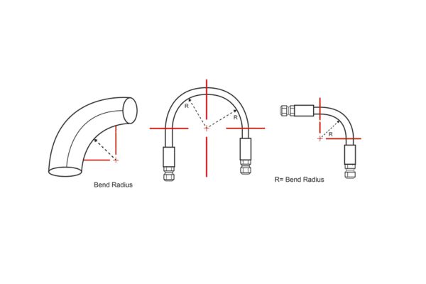
Minimum bend radius refers to the smallest radius to which a hydraulic hose can be bent without causing structural damage or performance degradation. This critical specification is typically expressed as a multiple of the hose’s outer diameter (OD). For example, a 1-inch OD hose with a bend radius factor of 6 would require a minimum bend radius of 6 inches. This measurement represents the radius to the centerline of the hose’s curvature, not to its inner edge. Adhering to minimum bend radius specifications prevents internal structural damage, maintains flow efficiency, and ensures the hose can withstand its rated pressure capacity throughout its service life.
How Bend Radius Affects Hose Performance and Longevity
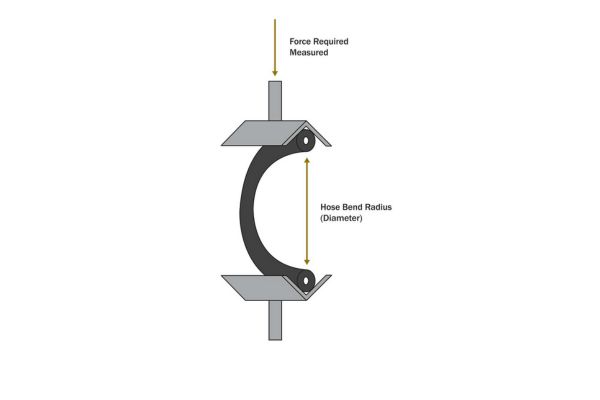
When a hydraulic hose bends, complex forces act upon its layered structure. The inner layer experiences compression while the outer layer undergoes tension. Excessive bending creates disproportionate stress distribution that can permanently deform reinforcement layers, leading to premature failure. Research indicates that bending a hose below its minimum radius can reduce service life by up to 70% through accelerated fatigue and structural weakening. Additionally, tight bends restrict flow area, creating turbulence and pressure drops that diminish system efficiency. Each 10% reduction below recommended bend radius typically results in approximately 5-8% flow restriction and corresponding performance losses.
The Relationship Between Hose Diameter and Bend Radius
As hydraulic hose diameter increases, the minimum bend radius factor typically increases proportionally. This relationship exists because larger diameter hoses experience greater structural stress during bending due to the increased distance between inner and outer curvatures. While smaller hoses might safely operate with bend radius factors of 4-6 times their outer diameter, larger industrial hoses often require factors of 8-12 or higher. This scaling relationship becomes particularly critical in high-pressure applications, where the combination of internal pressure forces and bending stress creates compound loading conditions that must be carefully managed through proper installation practices.
Wire-Braided Hydraulic Hose Bend Radius Requirements
Wire-braided hydraulic hoses represent the most common reinforcement design in fluid power applications, offering an optimal balance of pressure capacity, flexibility, and cost-effectiveness. The braided wire reinforcement layer provides structural integrity while allowing sufficient flexibility for installation in complex routing scenarios.
Single Wire Braid Construction and Bend Specifications
Single wire braid hydraulic hoses (commonly designated as SAE 100R1 or EN 853 1SN) feature one layer of high-tensile steel wire braided over a synthetic rubber inner tube. As highlighted in the original document, these hoses typically require a minimum bend radius of 6 times the hose’s outer diameter. This specification balances flexibility with structural integrity, allowing the single reinforcement layer to maintain its woven pattern without distortion when properly bent. For example, a 10mm outer diameter single-braided hose would require a minimum bend radius of 60mm to prevent structural damage and ensure optimal performance throughout its service life.
Double Wire Braid Standards for Enhanced Pressure Applications
Double wire braided hoses (such as SAE 100R2 or EN 853 2SN) incorporate two layers of braided steel wire reinforcement, significantly increasing pressure capacity but requiring more conservative bend radius specifications. These hoses typically demand a minimum bend radius of 7 times the outer diameter, reflecting the additional stiffness introduced by the second reinforcement layer. This increased bend radius requirement accommodates the complex interaction between the two braided layers during flexing, preventing friction-induced wear between reinforcement layers that could lead to premature failure. The higher bend radius factor ensures that stress distribution remains within acceptable limits across both reinforcement layers.
Triple Wire Braid Configurations for Extreme Conditions
Triple wire braided hoses, designed for extreme high-pressure applications, feature three layers of braided reinforcement for maximum pressure containment. These specialized hoses require a minimum bend radius of 8 times the outer diameter to accommodate the substantial reinforcement structure. The increased bend radius factor compensates for the significantly reduced flexibility resulting from the multiple reinforcement layers, preventing excessive stress concentration that could compromise the hose’s structural integrity. While these hoses offer exceptional pressure capacity, their installation demands careful planning to accommodate the larger space requirements associated with their more conservative bend radius specifications.
Wire-Spiral Hydraulic Hose Bend Radius Analysis
Wire-spiral hydraulic hoses utilize a different reinforcement structure than braided designs, featuring spirally wound wire layers that provide exceptional pressure resistance while maintaining reasonable flexibility. These hoses are particularly valued in high-pressure applications where structural integrity under extreme conditions is paramount. Their unique construction necessitates specific bend radius considerations during installation.
Medium Pressure Spiral Hose Bend Radius Guidelines
Medium pressure spiral hoses, commonly used in construction equipment and industrial machinery, require careful attention to bend radius specifications. As noted in the original document, these hoses typically demand a minimum bend radius of 9 times the outer diameter. This more conservative bend radius factor, compared to braided hoses, reflects the spiral reinforcement structure’s reduced flexibility. The spiral winding pattern creates a semi-rigid reinforcement layer that resists deformation but becomes vulnerable to structural damage when bent too sharply. Maintaining the 9x factor ensures that the spiral reinforcement maintains its structural integrity while accommodating necessary routing configurations.
High Pressure Spiral Hose Installation Considerations
High pressure spiral hoses, designed for extreme operating conditions exceeding 5,000 PSI, require even more conservative bend radius specifications. These hoses typically need a bend radius of 10-12 times the outer diameter, as specified in the original document. This substantial increase reflects the additional reinforcement layers and structural rigidity necessary for extreme pressure containment. The increased bend radius requirement prevents excessive stress on the reinforcement structure that could compromise pressure integrity or lead to catastrophic failure. When installing these hoses, technicians must carefully plan routing paths to accommodate these larger bend radius requirements, often necessitating additional space allocation compared to lower-pressure alternatives.
Comparing Spiral vs. Braided Construction Flexibility
The fundamental structural differences between spiral and braided reinforcement directly impact flexibility characteristics and bend radius requirements. While braided constructions feature interwoven wires that can adjust position slightly during bending, spiral constructions rely on wound wires that must maintain their relative positions. This difference explains why spiral hoses generally require bend radius factors 30-50% larger than their braided counterparts of similar pressure ratings. The trade-off for this reduced flexibility is enhanced pressure stability, improved impulse resistance, and superior performance in high-cycle applications where the consistent reinforcement structure resists fatigue better than braided alternatives.
Material Composition Impact on Bend Radius
The materials used in hydraulic hose construction significantly influence bend radius requirements and overall flexibility characteristics. Each layer of a hydraulic hose—inner tube, reinforcement, and outer cover—contributes to its bending behavior through specific material properties. Understanding these relationships enables more informed hose selection and installation planning.
Inner Tube Materials and Their Flexibility Characteristics
The inner tube material directly impacts a hose’s bend radius through its inherent elasticity and resistance to compression. Nitrile rubber (NBR), the most common inner tube material, offers good flexibility with a moderate temperature range (-40°F to 212°F), allowing for reasonable bend radius factors. Synthetic rubbers like EPDM provide enhanced flexibility, potentially reducing minimum bend radius by 5-10% compared to NBR, but with trade-offs in oil resistance. Polytetrafluoroethylene (PTFE) inner tubes, while excellent for chemical compatibility, exhibit less elasticity and typically increase minimum bend radius requirements by 15-20% compared to rubber alternatives. The inner tube’s wall thickness also plays a crucial role—thicker walls provide better pressure resistance but reduce flexibility, necessitating larger bend radii.
Reinforcement Layer Materials and Bend Performance
Reinforcement materials create the most significant impact on bend radius requirements. Standard carbon steel wire reinforcement offers a balance of strength and flexibility, establishing the baseline bend radius factors discussed in previous sections. Stainless steel reinforcement, while providing superior corrosion resistance, typically increases minimum bend radius by approximately 10% due to its different elastic properties. High-tensile steel wire can maintain similar flexibility while enhancing pressure ratings. Aramid fiber reinforcement (such as Kevlar®) reduces weight and provides excellent strength-to-weight ratio but generally requires larger bend radii due to its lower elasticity compared to steel. The wire diameter and spacing in reinforcement layers also significantly influence flexibility—finer wires with tighter spacing often allow smaller bend radii while maintaining pressure capacity.
Outer Cover Protection and Environmental Considerations
The outer cover material contributes to overall hose flexibility while providing environmental protection. Standard neoprene covers offer good flexibility and abrasion resistance without significantly impacting bend radius. Polyurethane covers, while providing superior abrasion resistance, can increase stiffness and minimum bend radius requirements by 5-15%, particularly in low-temperature environments. Special-purpose covers, such as MSHA-approved flame-resistant materials or textile-reinforced designs for extreme abrasion resistance, typically increase minimum bend radius requirements due to their enhanced thickness and reduced elasticity. Environmental factors like UV exposure or chemical contact can also alter material properties over time, potentially changing flexibility characteristics and necessitating more conservative bend radius allowances in challenging installation environments.
Temperature Effects on Hydraulic Hose Flexibility
Temperature conditions significantly influence hydraulic hose flexibility and consequently affect minimum bend radius requirements. Both extreme cold and high heat alter material properties throughout the hose structure, necessitating adjustments to installation practices to maintain system integrity and performance across varying operating environments.
Cold Temperature Considerations for Bend Radius
Cold temperatures dramatically reduce elastomer flexibility, causing rubber compounds to stiffen and become less compliant. At temperatures below 0°F (-18°C), standard hydraulic hose bend radius requirements should be increased by approximately 15-20% to compensate for reduced material flexibility. At extreme cold (-40°F/-40°C and below), this adjustment may need to increase to 30-50% depending on specific hose construction. Cold-induced stiffening particularly affects the inner tube and outer cover, creating resistance to bending and increasing the risk of cracking if forced beyond material limitations. For installations in consistently cold environments, specialized low-temperature compounds that maintain flexibility at reduced temperatures should be selected, or heating systems should be incorporated to maintain operational flexibility.
Hot Operating Environment Adaptations
High temperatures create the opposite effect, increasing material pliability but potentially reducing structural integrity. While elevated temperatures (above 150°F/65°C) may temporarily reduce minimum bend radius requirements by 5-10%, this apparent advantage comes with significant risks. Excessive heat softens rubber compounds and can accelerate material degradation, potentially leading to reduced pressure capacity and shortened service life. Additionally, reinforcement layers may experience reduced tensile strength at elevated temperatures, compromising their ability to contain pressure when combined with tight bending. For systems operating at sustained high temperatures, high-temperature-rated hoses with specialized compounds should be selected, and standard bend radius specifications should still be maintained despite the apparent increase in flexibility.

Temperature Fluctuation and Bend Radius Adjustments
Systems experiencing significant temperature fluctuations present unique challenges for bend radius management. Thermal cycling causes dimensional changes as materials expand and contract, potentially creating additional stress on hose structures already under bending loads. In these environments, installations should accommodate the most conservative bend radius requirement across the entire operating temperature range, typically adding 10-15% to the manufacturer’s specified minimum. Additionally, sufficient slack should be incorporated into the installation to accommodate length changes due to thermal expansion and contraction. Proper routing that allows natural movement during thermal cycling prevents stress concentration and extends service life in variable temperature applications.
Pressure Rating Correlation with Bend Specifications
The pressure rating of a hydraulic hose directly correlates with its bend radius requirements, creating a relationship that must be carefully considered during system design and installation. Understanding how different pressure classifications influence flexibility constraints enables more effective hose selection and routing strategies across diverse applications.
Low Pressure Applications (Under 1500 PSI)
Low pressure hydraulic systems, typically operating below 1500 PSI (103 bar), offer the greatest flexibility in terms of bend radius requirements. Hoses designed for these applications generally feature lighter reinforcement structures that allow for smaller bend radius factors—often 4-6 times the outer diameter for braided constructions. This enhanced flexibility facilitates installation in confined spaces and complex routing scenarios. However, even with this relative advantage, exceeding manufacturer specifications remains problematic. Field studies indicate that approximately 20% of premature failures in low-pressure applications stem from excessive bending, despite the more forgiving nature of these hoses. The reduced structural demands at lower pressures can create a false sense of security regarding installation practices, making adherence to proper bend radius specifications particularly important despite the apparent resilience of these components.
Medium Pressure Systems (1500-3000 PSI)
Medium pressure applications, ranging from 1500-3000 PSI (103-207 bar), represent the most common hydraulic system classification and typically utilize standard SAE 100R1 and 100R2 hose constructions. These hoses require more conservative bend radius factors—6-8 times the outer diameter—reflecting their enhanced reinforcement structures. At these pressure levels, the relationship between bend radius and pressure capacity becomes more pronounced, with testing showing that bending below minimum specifications can reduce burst pressure ratings by 15-25%. This reduction creates dangerous margins in systems that may experience pressure spikes during operation. Medium pressure installations must carefully balance space constraints with proper bend radius maintenance, often necessitating custom routing solutions or specialized adapter fittings to achieve compliant installations without compromising system layout.
High Pressure Requirements (Above 3000 PSI)
High pressure hydraulic systems, operating above 3000 PSI (207 bar) and sometimes exceeding 10,000 PSI (690 bar) in specialized applications, demand the most stringent adherence to bend radius specifications. These systems typically employ spiral-reinforced or multiple-braided constructions with bend radius factors of 8-12 times the outer diameter or greater. The relationship between bending and pressure capacity becomes critical at these extreme pressures, with even minor deviations from specified bend radius potentially reducing burst pressure ratings by 30% or more. This reduction eliminates crucial safety margins and significantly increases failure risk. High-pressure installations often require specialized routing strategies, including custom bent tubing sections for tight spaces, multiple fitting connections to navigate complex paths, or redesigned component layouts to accommodate the substantial space requirements of properly routed high-pressure hoses.
Conclusion
As fluid power systems continue to evolve, pressure capabilities continue to increase, and operational requirements become more demanding, the importance of proper bend radius management will grow every day. Armed with these principles, you will be able to design hydraulics that balance performance, reliability, and ease of maintenance, which will ultimately lead to lower operating costs and longer system life.
If you still have any confusion about how to install hydraulic hoses, or need quality hydraulic hoses, contact Topa and we’ll get you set up as soon as possible!
FAQ
What happens if I install a hydraulic hose with a bend radius smaller than recommended?
Installing a hydraulic hose with a bend radius below manufacturer specifications creates several immediate and long-term problems. Even if the hose doesn’t fail immediately, its service life may be reduced by 70-90%, leading to premature replacement and potential catastrophic failure during operation.
How do I measure bend radius correctly in an existing installation?
The most accurate method for measuring bend radius in an existing installation is the centerline approach. Identify the curved section of the hose and visually determine its arc. Measure from the center of this imaginary circle to the centerline of the hose (not the inner or outer edge).
Do different hydraulic fluids affect minimum bend radius requirements?
While hydraulic fluid type doesn’t directly change the manufacturer’s specified minimum bend radius, it can influence how strictly these specifications should be followed.
Can I use protective sleeves to allow tighter bends than specified?
Protective sleeves or bend restrictors cannot compensate for bending a hose beyond its minimum specified radius.
How do vibration and movement affect bend radius requirements?
Dynamic applications with significant vibration or movement typically require more conservative bend radius factors than static installations.
What’s the difference between bend radius and bend diameter, and why does it matter?
Bend radius measures from the center of the bend arc to the centerline of the hose, while bend diameter is twice this value (the full diameter of the imaginary circle formed by the bend).Bend radius measures from the center of the bend arc to the centerline of the hose, while bend diameter is twice this value (the full diameter of the imaginary circle formed by the bend).