
9 Shocking Flange Fitting Failures You Can Easily Avoid
Table of Contents
Introduction
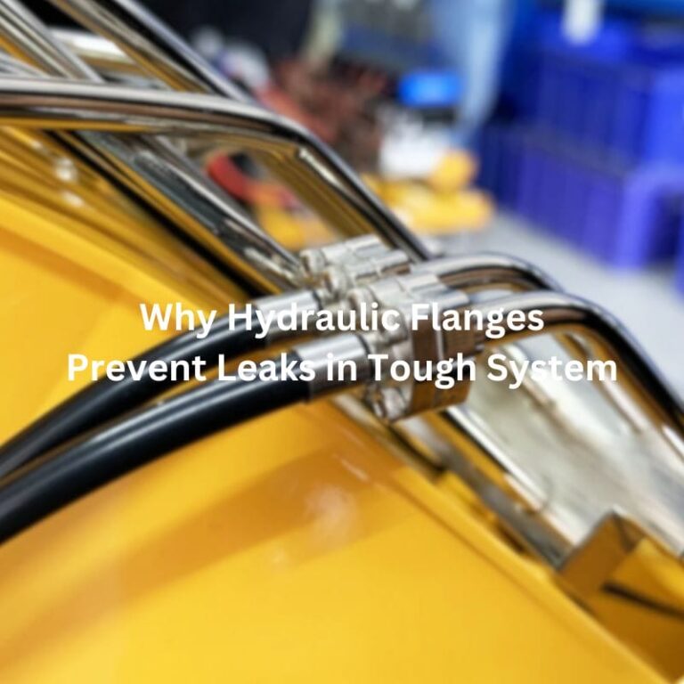
This article delves into the critical role of flange hydraulic fittings within industrial piping systems, emphasizing their importance in maintaining fluid flow under various operational conditions. It outlines the potential risks associated with flange hydraulic fitting failures, including leaks and industrial accidents, thereby highlighting the necessity of proper understanding, installation, and maintenance of these components. Through this discussion, the article aims to provide insights into ensuring the safety and efficiency of industrial operations by focusing on the correct practices related to flange fittings.
Understanding Flange Hydraulic Fittings
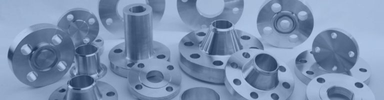
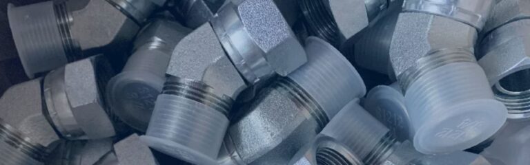
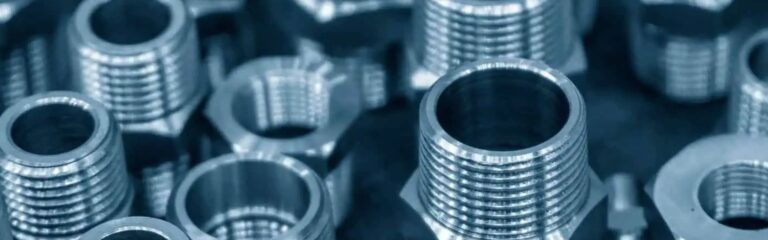
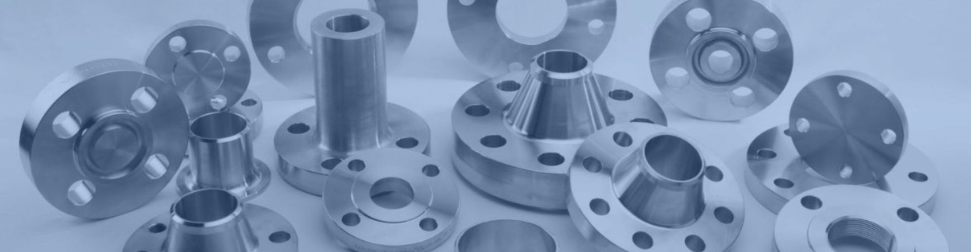
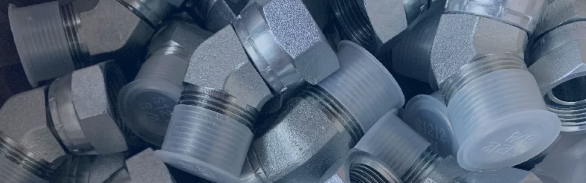
Flange hydraulic fittings are components that connect sections of pipes, valves, pumps, and other equipment within piping systems. Their primary function is to facilitate the assembly and disassembly of these systems for maintenance and repair purposes. These fittings are available in a range of shapes and sizes, tailored to meet specific operational demands such as pressure, temperature, and flow rates.
Industrial Applications
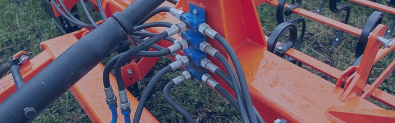
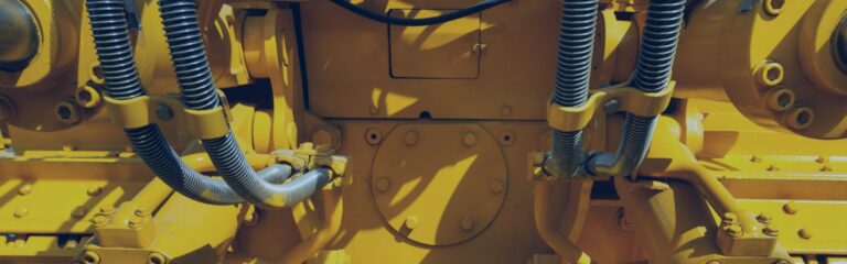
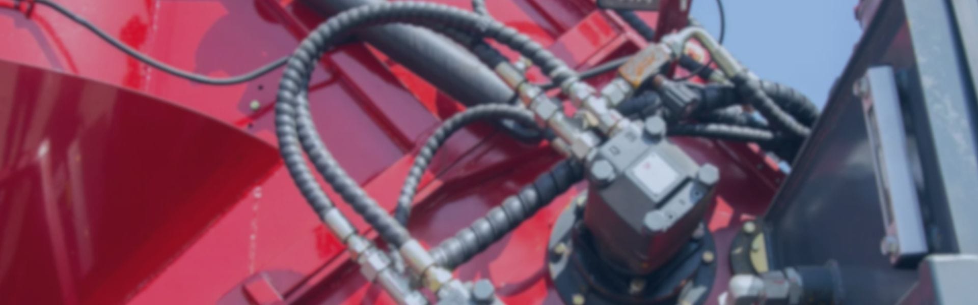
Flange hydraulic fittings are utilized in a wide array of industries. Key sectors include oil and gas, water treatment, and manufacturing. Their use across these diverse fields underscores their critical role in maintaining operational continuity and safety. The deployment of flange hydraulic fittings in critical industrial applications underlines their essential role in the seamless operation of piping systems. Their design and functionality ensure that systems can handle the required pressures and temperatures, thus safeguarding against potential failures and ensuring system integrity.

The Top 10 Flange Hydraulic Fitting Failures
Using Mismatched Flange and Pipe Sizes
Risks of Mismatch
When flange and pipe sizes are mismatched, the consequences can be immediate and severe. Even the slightest discrepancy in size can lead to gaps that compromise the seal, resulting in leaks. These leaks not only pose risks to safety and environmental standards but also lead to operational inefficiencies, including the loss of valuable resources and potential shutdowns for repairs. Moreover, mismatches can introduce undue stress on the pipeline, accelerating wear and tear and leading to premature failure of components.
Ensuring Correct Sizing
Preventing the pitfalls associated with mismatched flange and pipe sizes requires a meticulous approach throughout the lifecycle of the piping system:
- Design Phase: During the design phase, accurate specifications for both flanges and pipes must be established, ensuring that all components are compatible in size. This step often involves detailed engineering calculations and a thorough understanding of the operational requirements of the system.
- Procurement Process: When ordering flanges and pipes, double-checking the specifications is crucial to avoid mismatches. This includes verifying the nominal size, pressure rating, and other relevant standards to ensure they match the system’s design specifications.
- Installation and Assembly: During installation, careful examination of the flanges and pipes to ensure size compatibility is essential. This includes checking for any deviations in the specifications of the received components from those ordered.
- Ongoing Maintenance: Regular maintenance and inspections should include checks for signs of leaks, which could indicate sizing issues or wear and tear that has led to a mismatch over time. Addressing these issues promptly can prevent more significant failures.
Ignoring Flange Ratings
Flange ratings are a crucial aspect of flange fittings in piping systems. These ratings indicate the maximum pressure the flange can withstand at a specific temperature. Flange ratings ensure the safe operation of piping systems under various conditions. They are determined based on standards such as ASME B16.5 or the equivalent, which consider factors like material strength and design.
Consequences of Ignoring Flange Ratings
Failure to adhere to these ratings can result in:
- Leaks: When the system operates beyond the rated capacity, it may cause gasket failure or deformation, leading to leaks.
- Flange Failure: Exceeding the pressure rating can cause the flange itself to fail, which might result in a burst or catastrophic failure of the piping system.
- System Downtime: Any failure requires repairs or replacement, leading to operational downtime and financial losses.
Preventative Measures
- Selection: Ensure that the selected flange meets or exceeds the system’s maximum operating pressure and temperature.
- Installation: Proper installation according to the flange and gasket manufacturer’s guidelines is crucial to maintain the integrity of the flange connection.
- Inspection and Maintenance: Regular inspections can identify potential issues before they lead to failure. Maintenance should include checking for signs of wear, corrosion, or damage.
Neglecting Proper Gasket Selection

Gaskets are essential for creating a leak-proof seal between flange connections in piping systems. The selection of gaskets involves choosing the right material and size to match the operational conditions of the system. The material of the gasket must be compatible with the fluids being transported in the system to prevent chemical degradation. Common gasket materials include rubber, PTFE, and graphite, each with distinct properties suitable for different applications. The size and thickness of the gasket must precisely match the flanges to ensure a complete seal. Incorrect sizing can lead to gaps or excessive compression, both of which can compromise the seal’s integrity.
Temperature and Pressure Considerations
Gaskets must be selected based on the temperature and pressure conditions of the system. High temperatures or pressures require gaskets made from materials that can maintain their sealing properties under these conditions.
Overlooking Bolt Tightening Sequence
Bolt tightening sequence is crucial for ensuring the integrity of flanged connections in piping systems. This sequence impacts how evenly pressure is distributed across the flange, affecting the overall seal and stability of the connection.
Impact of Incorrect Sequence
Not following the correct sequence can lead to uneven pressure distribution. This imbalance can cause areas of the gasket to be compressed more than others, leading to potential leaks and reducing the effectiveness of the seal. Over time, this uneven pressure can also contribute to the degradation of the flange and gasket, leading to potential failures.
Correct Sequence for Bolt Tightening
The standard practice involves tightening bolts in a star pattern, similar to the method used for car wheel nuts. This approach ensures that pressure is applied evenly across the entire flange. The process typically involves several passes at increasing torque values to gradually and evenly compress the gasket and secure the flange.
Initial Hand Tightening: Bolts should be initially tightened by hand to ensure that the gasket is positioned correctly and that there are no gaps.
- First Pass: Using a torque wrench, the bolts are tightened in a star pattern to a specified fraction of the final torque value, often 30% to 50%.
- Subsequent Passes: Additional passes are made, increasing the torque value with each pass until the final torque specification is reached.
- Final Check: A final pass is made to verify that all bolts have been tightened to the correct torque.
Using Damaged or Worn Flanges

The condition of flanges in a piping system is critical to maintaining the integrity and safety of the operation. Flanges that are damaged or worn can compromise the system, leading to failures that may have severe consequences.
Risks of Using Damaged or Worn Flanges
Using flanges that are not in optimal condition can lead to several issues:
- Leaks: Damaged or worn flanges may not seal properly, leading to leaks that can affect system efficiency and safety.
- System Failure: In severe cases, the failure of a damaged or worn flange can result in system breakdown, causing operational disruptions and potential safety hazards.
- Increased Maintenance Costs: Using compromised flanges can lead to more frequent repairs and maintenance, increasing operational costs.
Importance of Regular Inspections
To prevent the risks associated with using damaged or worn flanges, regular inspections are essential. These inspections should assess the flanges for:
- Physical Damage: Checks for cracks, warping, or other physical damage that could impair the flange’s ability to form a seal.
- Corrosion: Inspection for signs of corrosion that can weaken the flange and make it susceptible to failure.
- Wear: Evaluation of the flange surface for signs of wear that could prevent a proper gasket seal.
Corrective Actions
When damaged or worn flanges are identified, the following corrective actions should be taken:
- Replacement: Flanges that are significantly damaged or worn should be replaced to ensure the integrity of the piping system.
- Repair: In some cases, minor damage may be repairable. However, this should only be done if the repair can restore the flange to a condition where it can safely perform its intended function.
- Upgrading: If recurrent issues with flanges are identified, it may be necessary to upgrade to flanges made of more durable materials or designs that better suit the operational conditions.
Incorrect Flange Alignment
Flange alignment in piping systems plays a crucial role in ensuring a tight and efficient seal between connections. Proper alignment is necessary to distribute pressure evenly and maintain the integrity of the seal, preventing potential leaks and failures.
Consequences of Misalignment
Misalignment of flanges can result in several issues within the piping system:
- Uneven Pressure Distribution: When flanges are not aligned correctly, it can lead to uneven pressure distribution across the gasket. This uneven pressure can cause the gasket to fail, resulting in leaks.
- Increased Stress on Piping Components: Incorrect alignment may also put additional stress on pipes, flanges, and bolts, leading to accelerated wear, fatigue, and eventual failure of these components.
- Reduced System Efficiency: Leaks and failures due to misalignment can significantly reduce the efficiency of the piping system, leading to increased maintenance costs and downtime.
Ensuring Correct Alignment
To avoid the issues associated with incorrect flange alignment, the following steps should be taken:
- Use of Alignment Tools: Specialized tools and techniques should be employed to ensure flanges are aligned correctly before bolting. This may include the use of flange alignment pins or levels.
- Inspection and Adjustment: Flanges should be visually inspected for alignment as part of the assembly process. Any misalignment detected should be corrected before proceeding with the bolting and sealing process.
Failure to Use the Correct Lubrication
Lubrication in flanged connections is critical for the proper tightening of bolts and effective compression of gaskets. It plays a pivotal role in achieving the desired seal integrity and longevity of the flange assembly.
Consequences of Inappropriate Lubrication
Using incorrect or inadequate lubrication can lead to several issues:
- Compromised Bolt Integrity: Incorrect lubrication may affect the torque applied to bolts, leading to under or over-tightening. This can strain the bolts, reducing their lifespan and potentially causing them to fail.
- Gasket Performance: Without proper lubrication, gaskets may not compress evenly or sufficiently, resulting in leaks. This undermines the integrity of the flange connection and the overall system.
- Leakage and Reduced Flange Life: Inadequate lubrication can accelerate wear on both the gasket and the flange surfaces, leading to early failure and reduced operational life of the flange assembly.
Selecting the Correct Lubrication
To ensure the longevity and reliability of flange connections, the correct lubrication must be selected based on:
- Compatibility with Gasket Material: The lubricant should not degrade the gasket material. Compatibility charts or manufacturer recommendations can guide the selection process.
- Operating Conditions: The lubricant must withstand the environmental and operational conditions (e.g., temperature, pressure, exposure to chemicals) of the system without losing its properties.
- Ease of Application: The chosen lubricant should be easy to apply uniformly across all bolt threads and gasket surfaces to ensure consistent performance.
Not Accounting for Thermal Expansion
Thermal expansion is a natural phenomenon where materials expand upon heating and contract when cooled. In piping systems, temperature variations are common, and if not properly accounted for, thermal expansion can significantly affect flange connections.
Effects on Flange Connections
- Misalignment: As materials expand or contract, flange connections can become misaligned, leading to leaks and reduced efficiency.
- Stress: Thermal expansion can introduce additional stress on flange connections, potentially leading to deformation or failure.
- Seal Integrity: Changes in material dimensions due to thermal expansion can compromise the integrity of seals, increasing the likelihood of leaks.
Mitigation Strategies
To mitigate the risks associated with thermal expansion in flange connections, the following strategies can be employed:
- Expansion Joints: Incorporating expansion joints into piping systems can accommodate thermal expansion and contraction, reducing stress on flange connections.
- Material Selection: Choosing materials with similar thermal expansion coefficients for both flanges and adjoining pipes can minimize the differential expansion effects.
- Design Considerations: Piping systems should be designed to allow for movement due to thermal expansion. This may include the strategic placement of loops or bends that can absorb the expansion.
Poor Welding Practices
Welding is a critical process in the fabrication and maintenance of flange connections in piping systems. The quality of welding directly impacts the integrity and reliability of the connection, making it essential to ensure high-quality welding practices.
Implications of Substandard Welding
- Compromised Connection Integrity: Poor welding can lead to weak joints that may fail under normal operating pressures, causing leaks or catastrophic failures.
- Increased Maintenance and Repair Costs: Substandard welding often requires rework, leading to increased maintenance costs and operational downtime.
- Safety Hazards: Faulty welding can pose significant safety risks, including the potential for explosive failures in systems carrying hazardous materials.
Ensuring High-Quality Welding
To prevent flange failures due to poor welding practices, several measures should be implemented:
- Certified Professionals: Only welders certified in the appropriate welding techniques should be employed. Certification ensures that welders have the necessary skills and knowledge to produce high-quality welds.
- Appropriate Welding Procedures: Welding procedures should be selected based on the materials being joined, the operating conditions of the system, and the specific requirements of the connection. These procedures should be strictly followed to ensure consistency and quality.
- Pre-Welding Preparation: Proper preparation of the welding surfaces is essential. This includes cleaning the surfaces to be joined and ensuring that they are properly aligned and fit for welding.
- Quality Control Measures: Implementing quality control measures, such as non-destructive testing (NDT) and inspection by qualified personnel, can help identify and rectify any defects in welds before the system is put into operation.
Conclusion
Meticulous attention to every detail, from the initial selection of components to installation to ongoing maintenance, is required to prevent flange fittings failures from occurring. Preventing flange joint failures is a collective endeavor that requires the participation of all stakeholders. By adhering to the guidelines outlined in this discussion, industries can achieve a higher standard of safety and efficiency and ensure that their operations continue to run smoothly and without disruption.
FAQ
What is a common cause of flange hydraulic fitting leaks?
Flange hydraulic fitting leaks often occur due to improper bolt tightening. Uneven or insufficient tightening can cause the gasket to misalign, leading to leaks. To avoid this, use a torque wrench and follow the manufacturer’s recommended torque specifications for uniform bolt tightening
How can I prevent flange misalignment during installation?
Misalignment can cause stress on the flange and lead to failures. Ensure that the flanges are aligned correctly before tightening the bolts. Use alignment tools and check for any angular or parallel misalignment to prevent undue stress on the system
Why is gasket selection crucial for flange fittings?
Using the wrong gasket material or size can lead to seal failure. Select a gasket that matches the chemical compatibility and temperature requirements of your hydraulic system. Refer to the manufacturer’s guidelines for the appropriate gasket type
What are the risks of using damaged or worn-out flanges?
Damaged or worn-out flanges can compromise the integrity of the seal and lead to leaks or bursts. Regularly inspect flanges for signs of wear, corrosion, or damage, and replace any faulty components immediately to maintain system safety
How does improper flange assembly affect performance?
Incorrect assembly, such as improper bolt sequence or uneven torque application, can cause uneven gasket compression, leading to leaks. Follow a star or cross pattern when tightening bolts and ensure even pressure is applied across the flange face
What should I consider when selecting flange materials?
Selecting the wrong flange material can result in corrosion or mechanical failure. Choose materials that are compatible with the operating environment and the fluids being transported. Consult with material compatibility charts and industry standards to make informed decisions


