NPSM Thread Meaning Unraveling the Basics

NPSM Thread Meaning: Unraveling the Basics

NPSM Thread Meaning: Unraveling the Basics

Table of Contents

Introduction

NPSM threads, characterized by their straight (non-tapered) profile, offer specific advantages in certain types of connections where sealing is achieved through means other than thread interference. In this post, readers will gain a comprehensive understanding of NPSM threads, including their definitions, history, technical specifications, and applications. We will delve into the basic characteristics that set NPSM threads apart, explore their evolution and industry adoption, and provide detailed technical insights.

What is NPSM?

Definition of NPSM

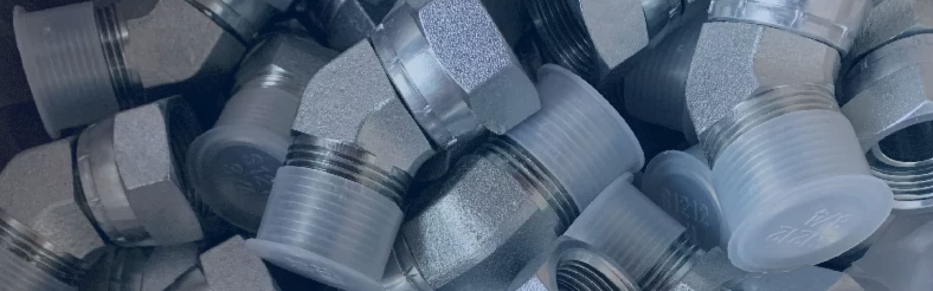
NPSM stands for National Pipe Straight Mechanical. It refers to a type of straight (non-tapered) thread used primarily in mechanical and hydraulic systems. Unlike tapered threads, which gradually decrease in diameter, NPSM threads maintain a consistent diameter throughout their length. This characteristic makes them ideal for certain types of connections where sealing is achieved through other means, such as O-rings or gasket seals, rather than thread interference.

Full Form of NPSM 

National Pipe: Refers to the standardization of pipe threads in the United States, ensuring consistency and compatibility across various applications and industries.

Straight Mechanical: Indicates that the threads are straight, as opposed to tapered, and are designed for mechanical connections where the primary function is to hold components together rather than to create a pressure-tight seal through thread deformation.

2NU9 NPSM adapters Topa

Basic Characteristics and Specifications

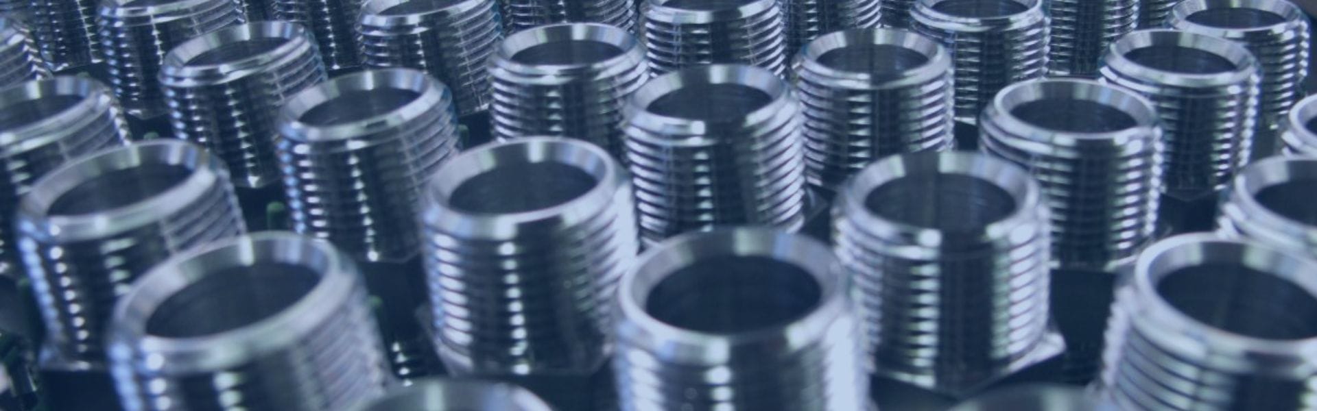
Thread Design: NPSM threads are designed with a parallel profile, meaning the thread crests and roots are consistent in diameter along the length of the thread.

Pitch: The distance between adjacent threads is uniform, ensuring a consistent and reliable fit.

Flank Angle: The angle between the threads is standardized to ensure compatibility with other NPSM components.

Brief History of NPSM Threads

NPSM threads have their roots in the early 20th century, developed as part of the effort to standardize industrial components. As industries grew, so did the need for uniform threading standards to ensure compatibility and interchangeability. This drive towards standardization led to the creation of various thread types, including NPSM. The National Pipe Straight Mechanical thread was developed to offer a reliable and leak-proof connection specifically for mechanical and hydraulic applications. Its design catered to the needs of industries requiring robust, high-pressure-resistant connections without the use of sealing compounds.

Origin and Standardization Process

The standardization of NPSM threads was driven by the American National Standards Institute (ANSI) and later incorporated into various international standards. This standardization process involved rigorous testing and validation to ensure that NPSM threads met the necessary criteria for strength, durability, and reliability. The adoption of NPSM threads by key industries helped solidify its place as a standard, ensuring that components from different manufacturers could be used interchangeably, thus facilitating global trade and industrial expansion.

Industries Using NPSM Threads

NPSM threads are widely used across various industries due to their reliable, leak-proof connections and ease of use. Some of the key industries include:

Automotive: NPSM threads are commonly found in hydraulic systems, brake lines, and fuel systems where secure, high-pressure connections are vital.

Aerospace: The aerospace industry uses NPSM threads in hydraulic and fuel systems, as well as in various mechanical assemblies that require high precision and reliability.

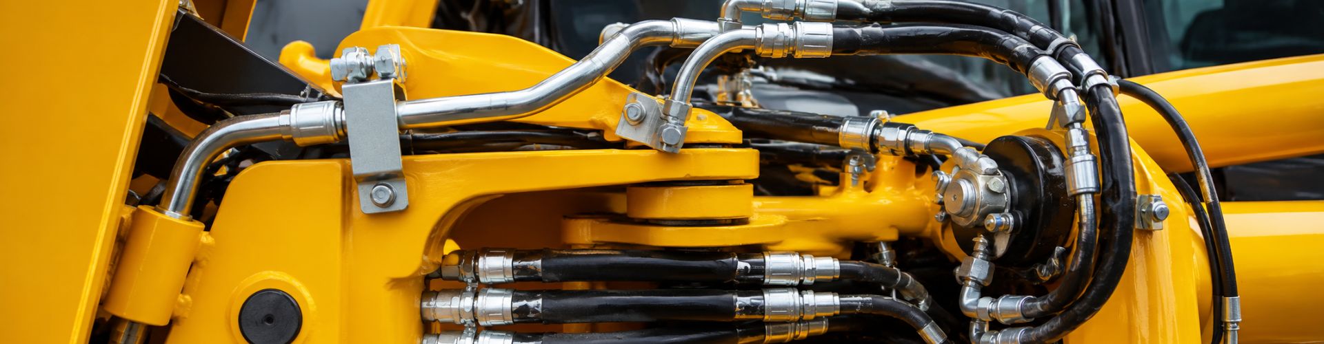
Manufacturing: In manufacturing, NPSM threads are used in machinery, hydraulic presses, and equipment that relies on fluid power for operation.

Construction: Heavy machinery and hydraulic tools in the construction industry often use NPSM threads for their robustness and ease of maintenance.

Oil and Gas: NPSM threads are used in pipelines, drilling equipment, and other high-pressure applications where leak prevention is critical.

Compatibility and Interchangeability
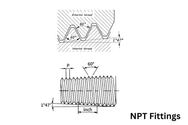
NPSM vs NPT

NPSM threads are straight threads designed for mechanical connections, relying on a gasket or O-ring to create a seal. In contrast, NPT threads are tapered, meaning the thread diameter decreases along the length, which helps create a seal through thread deformation and often requires a sealing compound like Teflon tape. While NPSM threads can connect to NPT threads, a leak-proof connection is not guaranteed without a gasket, as NPSM does not create a mechanical seal on its own. Therefore, understanding the differences is crucial for ensuring the proper application and avoiding potential leaks.
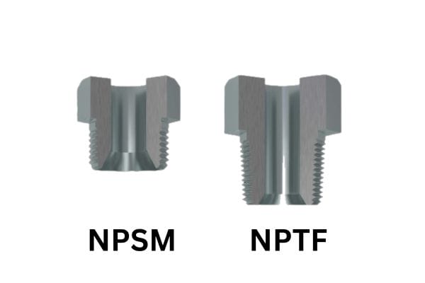
NPTF vs NPSM

NPSM vs NPTF

NPSM threads differ significantly from NPTF threads. NPTF threads, like NPT, are tapered but are designed to create a dry seal without the need for sealants, thanks to their precision machining. The threads deform to create a metal-to-metal seal, which is especially useful in fuel systems where contaminants from sealants must be avoided. NPSM threads, being straight, require an additional sealing mechanism and do not offer the same sealing capabilities as NPTF threads. Therefore, while NPTF threads can often replace NPT in critical applications, NPSM threads require careful consideration to ensure a proper seal.

NPSM vs BSP

NPSM and BSP threads both serve essential roles in mechanical and hydraulic systems, but they differ in design and application. NPSM threads are straight, maintaining a consistent diameter along their length, while BSP threads come in two types: BSPP (parallel) and BSPT (tapered). Both NPSM and BSPP are parallel threads, but they have different thread angles and pitch dimensions, making them incompatible without adapters.

NPSM threads are commonly used in applications where a mechanical connection is required, and the seal is achieved through other means like O-rings or gaskets, making them ideal for low-pressure systems in hydraulic and pneumatic equipment. BSP threads, on the other hand, are prevalent in plumbing and industrial fluid transfer systems, particularly in Europe and Asia. BSPT’s tapered design allows it to form a seal through thread interference, making it suitable for higher-pressure applications.

NPSM vs JIC

NPSM and JIC threads cater to different needs in hydraulic systems. While NPSM threads are straight and primarily rely on external seals, JIC threads are 37-degree flared fittings designed to create a metal-to-metal seal, offering superior leak resistance in high-pressure environments. The primary distinction lies in their sealing mechanism and application suitability.

Compatibility between NPSM and JIC threads requires careful consideration. NPSM threads can connect with other straight threads or fittings designed for O-ring seals, while JIC fittings require a matching 37-degree flare to ensure a proper seal. Adapters are often needed to bridge these systems. JIC fittings are preferred in high-pressure applications like hydraulic lines in heavy machinery and aviation, where a robust, leak-proof connection is critical. NPSM fittings, meanwhile, are suited for lower-pressure applications where external sealing mechanisms can be effectively utilized.

Challenges and Considerations

Common Problems Encountered with NPSM Threads

One of the most common issues with NPSM threads is improper sealing, especially in high-pressure applications. Since NPSM threads are straight and do not seal through thread interference, they rely instead on external seals like O-rings or gaskets. Any damage or misalignment of these seals can lead to leaks. For instance, if the O-ring is not seated correctly or is damaged, the integrity of the seal is compromised, resulting in fluid leakage.

Another frequent problem is thread galling during installation. Galling occurs when friction between the threads causes them to seize or weld together. This is particularly problematic during assembly and disassembly, as galling can make it extremely difficult to separate the components without causing damage to the threads. This issue is often exacerbated in stainless steel and aluminum fittings, where the material’s tendency to gall is higher.

Solutions and Preventative Measures

To address sealing issues, it is essential to ensure that the O-rings or gaskets used with NPSM threads are of high quality and compatible with the fluids and pressures involved. Regular inspection and replacement of these seals can prevent leaks. For example, using O-rings made from materials resistant to the specific chemicals in the hydraulic system can significantly enhance seal longevity and performance. Additionally, ensuring proper seating and alignment during installation can help maintain seal integrity.

To mitigate thread galling, applying appropriate lubricants during installation can reduce friction and prevent seizing. High-quality thread lubricants or anti-seize compounds specifically designed for use with hydraulic fittings are recommended. These lubricants create a barrier between the mating surfaces, reducing metal-to-metal contact and minimizing the risk of galling. Additionally, using tools and techniques specifically designed for NPSM threads can help maintain proper alignment and avoid damage. For instance, employing a torque wrench to apply precise torque values can ensure that the threads are not over-tightened, which is a common cause of galling.

Installation and Maintenance Tips

Best Practices for Installation

When installing NPSM threads, it is crucial to ensure that the threads and seals are clean and free from debris. Contaminants can compromise the connection and lead to leaks or thread damage. Therefore, thoroughly cleaning both the internal and external threads before assembly is essential.

Lubricate the threads to reduce friction and prevent galling. Using a suitable thread lubricant helps ensure a smooth assembly process. Align the components carefully to avoid cross-threading, which can damage the threads and compromise the connection. Cross-threading often occurs when the parts are not aligned correctly, leading to improper thread engagement.

Tighten the components according to the manufacturer’s specifications, typically using a torque wrench to ensure consistent and accurate application of force. Over-tightening or under-tightening can both lead to sealing issues and thread damage. Using proper tools designed for NPSM threads can also help achieve a secure and reliable connection. For example, wrenches and fittings specifically made for hydraulic systems are designed to apply the correct amount of force without damaging the threads.

Regular Maintenance Routines

To maintain the integrity of NPSM-threaded connections, implement a routine maintenance schedule that includes regular inspections for signs of wear, corrosion, or damage to the threads and seals. Visual inspections should focus on checking for leaks, which can indicate a failing seal, and looking for any signs of thread damage or deformation.

Replace any worn or damaged O-rings or gaskets promptly to prevent leaks. Over time, seals can degrade due to exposure to hydraulic fluids, temperature fluctuations, and mechanical stress. Regular replacement of these components ensures the continued reliability of the connection.

Periodically re-torque the connections to the recommended specifications to ensure they remain tight and secure. Vibration and thermal expansion can cause fittings to loosen over time, so periodic checks are necessary to maintain the correct torque levels.

Keeping a detailed maintenance log can help track the condition of each connection and identify any recurring issues that may need addressing. Documenting maintenance activities, including inspections, component replacements, and re-torquing events, provides valuable data that can be used to improve maintenance practices and predict potential problems before they lead to system failures.

Selecting the Right NPSM Threads

Material Compatibility

Choosing the correct material for NPSM threads is crucial for ensuring compatibility with the fluids and chemicals used in your hydraulic system. NPSM threads are available in a variety of materials, including stainless steel, brass, and carbon steel. Stainless steel is highly resistant to corrosion and is ideal for applications involving water, chemicals, or food-grade environments. Brass is often used in applications requiring good conductivity and corrosion resistance in mild environments. Carbon steel, while strong and durable, requires protective coatings to prevent rust in corrosive environments. It’s important to match the material of the threads with the specific requirements of the system to prevent chemical reactions that could weaken the connection or cause contamination.

Environmental Conditions

The operating environment plays a significant role in selecting the right NPSM threads. Consider factors such as exposure to corrosive substances, temperature extremes, and humidity levels. In corrosive environments, such as those involving saltwater or industrial chemicals, materials like stainless steel or brass with appropriate corrosion-resistant coatings are preferable. For applications exposed to high temperatures, selecting materials that can withstand thermal stress without deforming or losing strength is critical. Similarly, in extremely cold conditions, materials must be able to maintain their integrity without becoming brittle. Environmental factors can significantly affect the longevity and reliability of the threaded connection, so it is essential to choose materials and coatings that are well-suited to the specific conditions.

Pressure and Temperature Ratings

Understanding the pressure and temperature ratings of NPSM threads is essential for ensuring safety and performance in hydraulic systems. Each material and design of NPSM threads has specific pressure ratings, which indicate the maximum pressure the threads can safely withstand. These ratings are typically provided by manufacturers and should be matched to the operating conditions of your system. For example, high-pressure hydraulic systems require threads with high-pressure ratings to prevent leaks and failures. Similarly, the temperature rating indicates the range of temperatures within which the threads can operate effectively. Exceeding these ratings can lead to thread deformation, leaks, and potential system failures. Always consult manufacturer specifications to ensure that the NPSM threads selected meet or exceed the operational requirements of your application.

Conclusion

In this post, we explored the fundamentals of NPSM threads, including their definition, characteristics, and applications. By understanding the unique attributes and requirements of NPSM threads, you can make informed decisions that enhance system performance and prevent potential issues. We encourage you to apply the knowledge gained from this post to select the appropriate threads for your specific applications, ensuring long-lasting and secure connections.

FAQ

NPSM stands for National Pipe Straight Mechanical. These are straight (non-tapered) threads commonly used in mechanical and hydraulic systems.

Unlike NPT threads, which are tapered and seal through thread interference, NPSM threads are straight and rely on external seals such as O-rings or gaskets for sealing.

NPSM threads are often used in low-pressure systems, hydraulic equipment, and mechanical connections where external seals are utilized to ensure a leak-free joint.

NPSM threads can be made from a variety of materials, including stainless steel, brass, and carbon steel, depending on the application’s requirements and environmental conditions.

Common issues include improper sealing due to damaged or misaligned seals and thread galling during installation. Using high-quality seals and proper lubrication can mitigate these problems.

Regular inspections for wear, corrosion, and damage, along with routine replacement of O-rings or gaskets and periodic re-torquing of connections, are essential for maintaining the integrity of NPSM-threaded connections.

How to Measure Pipe Thread NPT Fittings

How to Measure Pipe Thread NPT Fittings

How to Measure Pipe Thread NPT Fittings

Table of Contents

Introduction

Accurate measurement of NPT fittings is crucial because even slight discrepancies can lead to significant issues. Precise measurement ensures a proper fit and prevents leaks, which can cause system failures, safety hazards, and costly repairs. Incorrect measurements can result in poor thread engagement, leading to weak connections that might fail under pressure. Moreover, ensuring accurate measurements helps maintain the integrity of the entire piping system, ensuring it operates efficiently and safely.

Tools Required for Measurement

Thread Gauges

Plug Gauges: Used to check the accuracy of the internal threads of a fitting. Plug gauges have a threaded section that matches the thread profile and pitch of the fitting being measured.

Ring Gauges: Used to measure the external threads of a fitting. Ring gauges are essentially threaded rings that can be screwed onto the fitting to verify thread accuracy.

hydraulic fittings measure tools Topa

Calipers

Digital Calipers: Provide a digital readout of the measurement, making them easy to use and read.

Dial Calipers: Use a dial indicator to show measurements. They are precise but require manual reading.

Vernier Calipers: Feature a sliding scale for measurements. They are very precise but require practice to read accurately.

Pitch Gauges: Pitch gauges are used to measure the distance between threads, known as the pitch. They consist of a set of blades with different thread profiles and pitches.

Rulers: Useful for quick, rough measurements of length and diameter. Ensure the ruler has fine markings for better accuracy.

Micrometers: Provide very precise measurements of small dimensions, such as thread pitch diameter. They are ideal for high-precision applications.

Step-by-Step Guide to Measuring NPT Fittings

Preparing the Fitting

Cleaning and Inspecting the Fitting:

Clean the Fitting: Use a brush and a suitable cleaning solution to remove any dirt, grease, or debris from the threads. This ensures that measurements are not affected by contaminants.

Inspect the Fitting: Examine the threads for any signs of damage, such as nicks, flattening, or corrosion. Damaged threads can lead to inaccurate measurements and poor fit.

Ensuring the Fitting is Free from Damage or Deformities:

Visual Inspection: Look for visible deformities or wear. Ensure the threads are intact and not worn out.

Check for Roundness: Use calipers to check the fitting’s roundness by measuring diameters at multiple points along the threads. Variations can indicate deformities.

Measuring the Thread Diameter

Internal and External Thread Measurement:

Internal Threads:

Procedure: Insert the caliper jaws into the fitting and gently expand them until they contact the internal threads. Ensure the caliper is perpendicular to the fitting’s axis to avoid skewed measurements.

Best Practices: Take multiple measurements at different points within the internal thread to ensure accuracy and consistency.

External Threads:

Procedure: Close the caliper jaws around the external threads, making sure they are perpendicular to the fitting’s axis. Measure at multiple points along the threads to ensure consistency.

Best Practices: Rotate the fitting and measure the external diameter at several points to verify uniformity. This helps in detecting any tapering or irregularities.

Using Calipers for Accurate Readings:

Digital Calipers:

Procedure: Turn on the caliper and zero it out before taking any measurements. Place the caliper jaws on the threads and read the digital display for an accurate measurement.

Advantages: Digital calipers are user-friendly and provide quick, precise readings, reducing the chance of human error.

Dial Calipers:

Procedure: Read the measurement from the dial indicator and the main scale. Combine these readings for the final measurement.

Advantages: Dial calipers offer reliable readings and are particularly useful in environments where digital tools might fail due to dust or moisture.

Vernier Calipers:

Procedure: Align the vernier scale with the main scale and read the measurement by noting where the scales align. This method requires more skill but can be very precise.

Advantages: Vernier calipers are highly accurate and do not rely on batteries, making them dependable in various conditions.

NPT Fittings sizes

Determining the Thread Pitch

Using Pitch Gauges to Measure the Thread Pitch:

Select the Correct Blade:

Procedure: Choose a pitch gauge blade that appears to match the thread pitch. Place it against the threads and ensure it fits snugly without gaps.

Verification: If the blade fits perfectly, you have identified the correct pitch. If not, try another blade until you find the one that matches.

Verify Fit:

Procedure: Place the pitch gauge on the threads and ensure that it meshes perfectly with the thread profile. The blade should fit snugly into the threads without any movement or gaps.

Confirmation: Check multiple points along the thread length to confirm that the pitch is consistent throughout.

Common Pitches for NPT Fittings:

Standard Pitches:

Details: Common NPT thread pitches include 11.5 TPI (Threads Per Inch) for 1/2″ NPT, 14 TPI for 1/4″ NPT, and 8 TPI for 1″ NPT. These pitches are standardized and can be verified using a pitch chart.

Procedure: Refer to a pitch chart to verify standard pitches for different sizes. This chart helps in quickly identifying the correct pitch for your specific fitting size.

Using a Thread Gauge

Verifying Thread Compatibility:

Internal Threads:

Procedure: Insert a plug gauge into the fitting. It should screw in smoothly and stop at the correct depth. Check for tightness without forcing.

Best Practices: Ensure the gauge is not forced into the threads, as this can damage both the gauge and the fitting.

External Threads:

Procedure: Screw a ring gauge onto the fitting. It should engage easily and fit snugly.

Best Practices: Rotate the gauge gently to ensure a proper fit. If resistance is encountered, inspect the threads for damage or debris.

Checking for Proper Fit and Alignment:

Procedure:

Ensure the gauge engages without cross-threading. A properly aligned gauge will screw on evenly and smoothly.

Rotate the gauge a few times to check for consistent engagement. If it feels uneven, recheck the thread measurements and alignment.

Recording and Interpreting Measurements

Documenting Measurements:

Procedure:

Record all measurements, including internal and external diameters, thread pitch, and gauge fit. Use a standardized form or spreadsheet for consistency.

Note any observations about the condition of the threads, such as damage or wear. This documentation helps in maintaining quality control and traceability.

Comparing Against Standard NPT Dimensions:

Procedure:

Compare the recorded measurements to standard NPT dimension charts. Ensure all dimensions fall within the acceptable range for the specific NPT size.

Identify any discrepancies and re-measure if necessary to confirm accuracy. Consistent measurements across different points help in verifying the fitting’s compliance with standards.

Common Challenges and Solutions

Dealing with Worn or Damaged Threads

Identifying Worn or Damaged Threads:

Visual Inspection: Examine the threads closely for signs of wear, such as flattening, nicks, or corrosion. Use a magnifying glass if necessary to spot minor damages.

Feel Test: Run your fingers over the threads. Rough or uneven areas can indicate wear or damage.

Thread Engagement: Attempt to engage a thread gauge. If the gauge does not fit smoothly or stops prematurely, the threads may be worn or damaged.

Solutions for Accurate Measurement Despite Wear:

Use of Thread Restoration Tools: Consider using a thread file or thread chaser to restore slightly damaged threads before measurement.

Selecting Undamaged Areas: If possible, measure undamaged sections of the thread to get more accurate readings.

Gauge Verification: Use multiple types of gauges (plug and ring) to cross-check measurements and confirm thread integrity.

Digital Profiling: Employ advanced digital thread profiling tools to capture the thread’s dimensions accurately despite wear.

Handling Large or Small Fittings

Techniques for Measuring Large Diameter Fittings:

Large Calipers or Micrometers: Use specialized large calipers or micrometers designed for measuring large diameters. Ensure they have the range and accuracy needed for the fitting size.

Segmented Measurements: For very large fittings, take measurements in segments and combine them to get the overall dimension. Use a flexible tape measure for circumference and convert to diameter using the formula (Diameter = Circumference / π).

Support and Stability: Ensure the fitting is properly supported and stable during measurement to avoid inaccuracies due to movement.

Precision Methods for Small Fittings:

Fine-Tipped Calipers: Use calipers with fine tips that can accurately fit into small threads without damaging them.

Micrometers for Small Threads: Employ micrometers designed for small threads to ensure precision.

Magnification: Use a magnifying tool or microscope to assist in reading measurements on small fittings, ensuring clarity and accuracy.

NPT Threads Need Sealant

Interpreting Ambiguous Results

Addressing Inconsistent or Unclear Measurements:

Re-Measurement: Re-measure the fitting using different tools and techniques to verify initial readings. Consistency across multiple measurements indicates reliability.

Cross-Reference with Standards: Compare measurements with standard dimensions for NPT fittings to identify any anomalies.

Third-Party Verification: If measurements remain ambiguous, seek third-party verification using calibrated instruments or professional metrology services.

Best Practices for Re-Measurement:

Calibrate Instruments: Ensure all measurement tools are calibrated correctly before re-measuring to eliminate tool-related errors.

Consistent Environment: Perform measurements in a consistent environment, avoiding changes in temperature or humidity that might affect readings.

Multiple Points: Measure at multiple points along the thread to average out any minor discrepancies. This practice helps in identifying true dimensions versus localized wear or damage.

How to Select the Right Size NPT Thread Fitting

Selecting the correct size NPT (National Pipe Tapered) thread fitting is crucial for ensuring a secure and leak-proof connection in your piping system. Here is a step-by-step guide to help you choose the right size NPT fitting for your application.

Understand NPT Sizing

Nominal Pipe Size (NPS):

NPT fittings are designated by their nominal pipe size (NPS), which does not directly correspond to the actual outside diameter (OD) of the pipe.

The NPS system is used to standardize the sizing of pipes and fittings, making it easier to match components.

Thread Pitch:

NPT threads have a specific pitch, which is the number of threads per inch (TPI). Common pitches include 11.5 TPI for 1/2″ NPT, 14 TPI for 1/4″ NPT, and 8 TPI for 1″ NPT.

Determine the Application Requirements

Pressure Rating

Identify the Operating Pressure:

Determine the maximum pressure that the piping system will experience during operation. This includes considering any potential pressure spikes or surges.

Typical applications, such as residential plumbing, industrial processes, or hydraulic systems, will have different pressure requirements.

Select the Appropriate Pressure Rating:

NPT fittings are available in various pressure ratings, often indicated by the manufacturer. These ratings are based on the material and construction of the fitting.

Ensure the selected fitting can handle the operating pressure without risk of failure. For high-pressure applications, opt for fittings made from robust materials like stainless steel.

Material Compatibility

Evaluate the Fluid or Gas Being Transported:

Consider the chemical properties of the fluid or gas flowing through the pipes. This includes its corrosiveness, temperature, and any potential reactivity with the fitting material.

Choose the Appropriate Material:

Brass: Ideal for water, oil, and air applications due to its corrosion resistance and durability.

Stainless Steel: Suitable for harsh environments, high-pressure systems, and corrosive substances.

Plastic: Often used for low-pressure applications and when chemical compatibility with specific fluids is required (e.g., in chemical processing or potable water systems).

Temperature Considerations

Ensure the fitting material can withstand the operating temperatures of the system. High temperatures can affect the strength and integrity of some materials, particularly plastics.

End Connections:

Identify Connection Types:

Determine whether the system requires male or female NPT threads. Male threads fit into female threads, and vice versa.

Consider if the fitting needs to connect to other types of fittings or adapters, such as JIC, BSP, or SAE.

Consider the System Configuration:

Evaluate the layout and configuration of the piping system. Ensure the selected fitting type aligns with the connection points in your system for a seamless and secure fit.

Select the Correct Fitting

Match the Size:

Measure and Verify:

Using the previously gathered measurements (outside diameter, thread pitch), select the fitting size that matches the nominal size and thread pitch of your pipes.

Use standardized size charts to cross-reference and ensure compatibility.

Ensure Compatibility:

Double-check that the fitting type (male or female) matches the connection points in your system. Misalignment can lead to leaks and system failure.

Verify the Fit:

Test Assembly:

Assemble the fitting with the pipe to verify a proper fit. The threads should engage smoothly without excessive force. If there is resistance or cross-threading, the fitting size or thread type might be incorrect.

Check that the fitting threads fully engage and create a tight seal when properly torqued. The fitting should be snug but not overtightened, which can strip threads or cause damage.

Evaluate Thread Engagement:

Ensure that the fitting threads are properly aligned and engage uniformly. Misaligned threads can compromise the seal and lead to leaks.

Conclusion

Ensuring accuracy and consistency throughout this process is vital to maintaining the integrity and functionality of piping systems. Precise measurements prevent leaks, ensure proper fit, and enhance the overall performance and safety of the system.  Prioritizing accurate measurement is essential for the efficiency and safety of any piping system. By adopting best practices and utilizing advanced measurement tools, professionals can ensure that their systems operate smoothly and effectively.

FAQ

NPT stands for National Pipe Tapered. It is a standard for tapered threads used to create a tight seal in pipe fittings.

To measure the thread size, you need to measure the outside diameter (OD) of the male thread or the inside diameter (ID) of the female thread and determine the thread pitch using a thread pitch gauge.

The primary tools required are calipers (digital, dial, or vernier), thread pitch gauges, and thread plug or ring gauges. These tools help ensure precise measurements of the diameter and pitch.

Accurate measurements ensure a proper fit and a tight seal, preventing leaks and system failures. Incorrect measurements can lead to poor thread engagement and potential safety hazards.

NPT fittings are not compatible with BSP or SAE threads due to differences in thread design and pitch. Using the correct type of fitting for each specific thread standard is crucial.

NPT fittings are commonly made from materials such as brass, stainless steel, and plastic. The choice of material depends on the application, environmental conditions, and the substances being transported through the pipes.

How to Install NPT Fittings

How to Install NPT Fittings

How to Install NPT Fittings

Table of Contents

Introduction

Proper installation of NPT fittings is crucial to ensure leak-proof connections. Incorrect installation can lead to gaps or misalignment in the threads, causing leaks that can compromise system integrity and lead to costly repairs or downtime. Accurate installation not only prevents leaks but also enhances the safety and efficiency of the entire system. Well-installed NPT fittings minimize the risk of hazardous leaks, ensuring safe operation in high-pressure and high-temperature environments.

Tools and Materials Needed

Pipe Wrenches

Pipe wrenches are crucial for gripping and turning pipes and fittings during installation. Their adjustable jaws allow for a secure grip on various pipe sizes, providing the leverage to tighten or loosen fittings effectively.

Thread Sealant (e.g., Teflon Tape, Pipe Dope)

Thread sealant is essential for ensuring a leak-proof seal between threaded connections. Teflon tape and pipe dope are commonly used to fill the gaps in the threads, preventing leaks and enhancing the overall integrity of the connection.

Pipe Cutter

A pipe cutter is used to cut pipes to the required length. It provides a clean and precise cut, ensuring the pipe ends are smooth and ready for threading. Using a pipe cutter also reduces the risk of damaging the pipe compared to other cutting methods.

Thread Gauge

A thread gauge is used to measure and verify the thread size and pitch of pipes and fittings. This tool ensures that the threads are compatible, which is crucial for achieving a proper seal and avoiding leaks.

Step-by-Step Installation Guide

Preparation

Before beginning the installation, carefully inspect the fittings and pipes for any signs of damage or defects, such as cracks, dents, or irregularities. Cleaning is also crucial; use brushes and rags to remove any dirt, oil, or debris from the threads. This ensures a clean surface for the thread sealant to adhere to, which is essential for creating a leak-proof seal.

Choosing the Right Thread Sealant

Selecting the appropriate thread sealant is vital for the success of the installation. Teflon tape and pipe dope are the two most common options. Teflon tape is ideal for most standard applications due to its ease of use and effectiveness in preventing leaks. Pipe dope, or thread compound, provides a more durable seal and is often used in high-pressure or high-temperature environments. Consider the specific requirements of your application when choosing the sealant.

cut copper tube

Cutting and Threading the Pipe

Measuring and Marking the Pipe

Accurate measurement is key to ensuring that the pipe fits correctly within the system. Use a tape measure to determine the required length, and mark the pipe with a pencil or marker at the desired cut point. Double-check measurements to avoid any errors that could compromise the installation.

Using a Pipe Cutter

Secure the pipe in a pipe vise or similar tool to prevent movement. Place the pipe cutter on the marked line, ensuring it is aligned correctly. Rotate the cutter around the pipe, tightening it gradually until the pipe is cut through completely. This method ensures a clean, straight cut, which is necessary for proper threading.

Threading the Pipe with a Die Set

After cutting, the next step is to thread the pipe. Use a die set appropriate for the pipe size. Apply threading oil to the pipe end to lubricate and cool the threads during the process. Position the die over the pipe end and turn it clockwise, ensuring even pressure to create consistent threads. Continue threading until the required length of the threads is achieved. Clean the threads with a brush to remove any metal shavings or debris.

Applying Thread Sealant

How to Apply Teflon Tape Properly

Start by wrapping Teflon tape around the male threads of the pipe. Begin at the end of the pipe and wrap the tape clockwise, overlapping each layer by about half the tape’s width. Apply 2-3 layers of tape, ensuring that the tape is snug and flat against the threads. Avoid over-taping, as this can cause difficulty when threading the fittings together.

Using Pipe Dope Effectively

If using pipe dope, apply a thin, even layer of the compound to the male threads of the pipe. Use a brush or the applicator provided to spread the dope, ensuring it covers all the threads but does not clog them. Pipe dope is particularly useful for applications where the connection may need to be adjusted after initial assembly.

Assembling the Fittings

Hand-Tightening the Fittings

Begin by screwing the fitting onto the pipe by hand. Hand-tightening ensures that the threads are properly engaged without the risk of cross-threading. Turn the fitting clockwise until it becomes difficult to turn by hand.

Final Tightening with a Pipe Wrench

Once hand-tightened, use a pipe wrench to secure the fitting further. Position the wrench on the fitting and turn it clockwise, applying firm but controlled pressure. Avoid over-tightening, as this can damage the threads or the fitting itself. Generally, a few additional turns after hand-tightening are sufficient to create a secure seal.

Checking Alignment and Fit

After tightening, check the alignment and fit of the pipe and fitting. Ensure that the connection is straight and properly seated. Misalignment can cause stress on the connection and lead to leaks or failure.

install NPT fitting

Testing the Connection

Pressure Testing for Leaks

Once the fittings are assembled, it’s crucial to test the connection for leaks. Perform a pressure test by filling the system with water or air and pressurizing it to the operating pressure. Observe the connection for any signs of leakage. If a leak is detected, depressurize the system and re-tighten the fitting or reapply thread sealant as needed.

Visual Inspection for Proper Installation

In addition to pressure testing, conduct a thorough visual inspection. Check for any signs of thread damage, misalignment, or improper sealing. Ensure that all fittings are correctly installed and that there are no visible gaps or irregularities. A meticulous inspection can prevent future issues and ensure the reliability of the connection.

Common Installation Mistakes and How to Avoid Them

Over-tightening

Over-tightening is a frequent mistake during the installation of NPT fittings. While it might seem that tightening the fitting as much as possible will ensure a leak-proof connection, excessive force can actually damage the threads, distort the fitting, or even crack the pipe. This compromises the integrity of the connection and can lead to leaks or failures.

How to Prevent Over-tightening:

Hand-Tightening First: Always begin by tightening the fitting by hand. This helps to ensure the threads are properly engaged without any cross-threading.

Use a Pipe Wrench Sparingly: When using a pipe wrench, apply moderate force. Typically, after hand-tightening, only 1-2 additional turns with the wrench are necessary. Avoid using excessive force.

Follow Manufacturer Guidelines: Refer to the manufacturer’s recommendations for torque specifications if available. This provides a guideline on how much force to apply without risking damage.

Practice and Experience: With experience, you’ll develop a feel for how tight is “tight enough.” Practicing on spare fittings can help you learn the right amount of force to use.

Improper Use of Thread Sealant

Common Errors with Teflon Tape and Pipe Dope

Thread sealant is crucial for ensuring leak-proof connections, but improper application can cause issues. Common mistakes include using too much or too little sealant, incorrect wrapping techniques, and choosing the wrong type of sealant for the application.

How to Avoid Common Errors:

Using Teflon Tape:

Correct Wrapping Direction: Wrap the tape in the same direction as the threads (clockwise when looking at the pipe end). This ensures the tape does not unravel when the fitting is tightened.

Proper Coverage: Apply 2-3 layers of Teflon tape, overlapping each layer by about half the tape’s width. Ensure the tape covers the threads completely but does not extend beyond them.

Using Pipe Dope:

Even Application: Apply a thin, even layer of pipe dope to the male threads using a brush or the applicator provided. Avoid clogging the threads with excess compound.

Compatibility: Choose a pipe dope that is compatible with the materials and the type of fluid or gas being transported. Some pipe dopes are designed for specific applications and may not be suitable for all uses.

Incorrect Thread Engagement

Ensuring Proper Threading to Avoid Leaks

Incorrect thread engagement can occur when the threads are not aligned properly, leading to cross-threading or insufficient engagement. This results in weak connections that are prone to leaking and failure.

How to Ensure Proper Thread Engagement:

Inspect Threads Before Use: Before installation, inspect the threads on both the pipe and fitting for any damage or irregularities. Damaged threads should be repaired or the component replaced.

Align Threads Correctly: When assembling the fitting, ensure the threads are properly aligned before starting to tighten. Begin threading by hand to avoid cross-threading.

Use a Thread Gauge: A thread gauge can help verify that the threads are the correct size and type, ensuring compatibility and proper engagement.

Thread the Pipe Correctly: When cutting and threading the pipe, use the correct tools and techniques to create precise threads. Apply threading oil to reduce friction and ensure clean, well-formed threads.

Troubleshooting Tips

Identifying Leaks

Common Signs and Causes

Leaks in NPT fittings can be identified through various signs and have several common causes:

Visible Drips or Moisture: The most obvious sign of a leak is visible moisture, drips, or puddles around the fitting. This indicates that the seal is not holding properly.

Pressure Drop: A noticeable drop in system pressure can indicate a leak somewhere in the piping system. Regular pressure monitoring can help detect this issue.

Hissing Sound: For gas systems, a hissing sound near the fitting may indicate escaping gas, signifying a leak.

Corrosion or Rust: Over time, leaks can lead to rust or corrosion around the fitting, which can be a visual cue to the problem.

Fluid Stains: Stains or discoloration on or around the pipe and fittings can also indicate a slow leak that needs addressing.

Common Causes of Leaks:

Improper Thread Engagement: Threads that are not properly aligned or cross-threaded can result in leaks.

Inadequate Thread Sealant: Insufficient or improperly applied thread sealant can fail to fill the gaps in the threads, leading to leaks.

Over-tightening or Under-tightening: Both over-tightening and under-tightening can compromise the integrity of the connection.

Damaged Threads: Threads that are worn, damaged, or corroded can prevent a proper seal from forming.

Fixing Leaks

Reapplying Thread Sealant

Disassemble the Connection: Carefully unscrew the fitting to expose the threads. Use a pipe wrench if necessary, but avoid excessive force that could damage the threads further.

Clean the Threads: Remove any old thread sealant, dirt, or debris from the threads using a brush and rags. Ensure both the male and female threads are clean and dry.

Apply New Sealant:

Teflon Tape: Wrap the tape clockwise around the male threads, overlapping each layer by about half the tape’s width. Apply 2-3 layers for a good seal.

Pipe Dope: Apply a thin, even layer of pipe dope to the male threads, ensuring full coverage without clogging the threads.

Reassemble the Fitting: Screw the fitting back onto the pipe by hand, then use a pipe wrench to tighten it further. Avoid over-tightening.

Retightening Connections

Hand-Tighten First: Ensure the fitting is initially hand-tightened to engage the threads properly.

Use a Pipe Wrench: Apply moderate force with a pipe wrench to tighten the fitting further. Turn it until you feel resistance, then give an additional quarter turn. Check for leaks and tighten further if necessary, but avoid excessive force.

When to Reinstall

Recognizing When to Start Over with New Fittings

Severe Thread Damage: If the threads are significantly worn, corroded, or damaged, reapplying sealant will not be effective. New fittings and pipes should be used to ensure a proper seal.

Persistent Leaks: If leaks persist after multiple attempts to reapply sealant and retighten the fitting, it may indicate a deeper issue with the components. Starting over with new fittings is the best course of action.

Misaligned or Cross-Threaded Connections: If the threads were cross-threaded or misaligned during installation, the integrity of the connection is compromised. Disassemble and start over with new, properly aligned fittings.

Old or Worn Fittings: Over time, fittings can wear out due to repeated use, exposure to harsh conditions, or corrosion. Inspect the fittings regularly and replace them if they show signs of wear or damage.

Conclusion

Installing NPT fittings requires careful attention to detail and adherence to proper techniques to ensure leak-proof connections. The process involves preparing the pipes and fittings, cutting and threading the pipe, applying the correct thread sealant, assembling the fittings, and conducting thorough testing. Each step is crucial in achieving a secure and reliable connection that will withstand the demands of various applications. We encourage you to share your experiences, tips, and insights on installing NPT fittings.

FAQ

NPT (National Pipe Taper) threads have a taper of 1/16 inch per inch, which means the diameter decreases along the length of the thread. This taper creates a tight, leak-proof seal when the fitting is tightened. Other types of pipe threads, such as BSP (British Standard Pipe), have different threading standards and are not directly compatible with NPT threads.


NPT fittings should be hand-tightened until snug, then further tightened with a pipe wrench by 1-2 additional turns. Avoid over-tightening, as it can damage the threads or fitting, leading to leaks or failure.

Yes, you can use both Teflon tape and pipe dope together for added security. Apply the Teflon tape first, wrapping it clockwise around the male threads, then apply a thin layer of pipe dope over the tape. This combination can provide a more effective seal, especially in high-pressure applications.

If a leak is detected, first depressurize the system and carefully disassemble the fitting. Clean the threads and reapply the thread sealant (Teflon tape or pipe dope) properly. Reassemble the fitting, ensuring it is tightened correctly. If the leak persists, inspect for damaged threads and consider replacing the fitting.

NPT fittings should be inspected regularly, especially in high-use or critical applications. A visual inspection every few months, combined with annual pressure testing, can help identify and address potential issues before they lead to significant problems.

NPT fittings can be reused if they are in good condition and the threads are not damaged. However, it is important to clean the threads thoroughly and reapply thread sealant before reassembling. For critical applications, it is often best to use new fittings to ensure a reliable seal.

Grease Fitting Leaking Troubleshooting Guide

Grease Fitting Leaking? Troubleshooting Guide

Grease Fitting Leaking? Troubleshooting Guide

Table of Contents

Introduction

Leaking grease fittings can pose significant problems for machinery and operations. When grease fittings leak, the lubrication intended for the internal components is lost, leading to inadequate lubrication and increased friction. This can result in accelerated wear and tear, overheating, and even failure of critical machinery parts. The impacts of such failures can be costly, causing downtime, expensive repairs, and potential safety hazards. Addressing grease fitting leaks promptly is essential to maintain the integrity and efficiency of machinery, ensuring continuous and reliable operation.

Causes of Grease Fitting Leaks

Worn or Damaged Fittings

Identification of Wear and Tear:

Regular inspections should be conducted to identify any signs of wear and tear on grease fittings. Look for visible cracks, which can compromise the integrity of the fitting and lead to leaks.

Corrosion is another indicator, often caused by exposure to harsh environments or chemicals. Corroded fittings may not provide a proper seal, resulting in grease leakage.

Deformation, such as bending or warping, can occur due to mechanical stress or impact. This physical damage can prevent the fitting from functioning correctly.

Common Signs of Damage:

Leaking Grease: One of the most apparent signs is the presence of grease around the fitting or on nearby components. This indicates that the fitting is not sealing properly.

Difficulty in Applying Grease: If it’s hard to inject grease into the fitting, it might be blocked or damaged. This can be due to internal blockages or a malfunctioning check valve.

The Fitting Not Accepting Grease: If grease cannot be applied at all, the fitting might be severely damaged or clogged, necessitating replacement.

rust Grease Fitting Topa

Improper Installation

Techniques for Proper Installation:

Ensure the Fitting is Clean: Before installation, clean both the fitting and the receiving port to remove any debris or contaminants. This ensures a proper seal and prevents contaminants from entering the lubrication system.

Use the Correct Tools: Specialized tools such as grease fitting installers or wrenches should be used to avoid damaging the fitting during installation. Avoid using improper tools that can cause deformation.

Follow Manufacturer Guidelines: Each type of fitting may have specific installation procedures. Adhering to the manufacturer’s guidelines ensures that the fitting is installed correctly and functions as intended.

Consequences of Incorrect Installation:

Leaks: Incorrect installation can result in poor sealing, causing grease to leak out of the fitting.

Improper Lubrication: If a fitting is not installed correctly, grease may not reach the intended parts, leading to inadequate lubrication and increased wear on machinery components.

Potential Damage to Machinery: Improperly installed fittings can lead to mechanical failures, increased friction, and overheating, causing severe damage to the machinery over time.

Contaminated Grease

How Contaminants Enter the System:

Through Damaged Fittings: Damaged or improperly sealed fittings can allow dirt, water, and other contaminants to enter the lubrication system.

Improper Storage: Storing grease in open or unsealed containers can lead to contamination. Always store grease in clean, sealed containers to maintain its purity.

Dirty Application Tools: Using dirty grease guns or other tools can introduce contaminants directly into the fittings and lubrication system.

Effects of Contaminated Grease on Fittings:

Clogging: Contaminants can clog the fitting or the lubrication channels, preventing grease from reaching critical components.

Increased Wear: Contaminated grease can act as an abrasive, accelerating wear and tear on both the fittings and the machinery.

Potential Damage to the Machinery: The presence of contaminants can lead to corrosion, increased friction, and ultimately mechanical failures, compromising the reliability and lifespan of the equipment.

remove Stuck Grease Fitting

Over-Pressurization

Understanding Pressure Limits:

Each grease fitting has a maximum pressure rating that should not be exceeded. This rating ensures the fitting can handle the pressure required to inject grease without failing.

Effects of Exceeding Pressure Limits:

Damaged Fittings: Excessive pressure can cause the fitting to crack or deform, resulting in leaks.

Burst Hoses: Over-pressurization can also cause the hoses connected to the fittings to burst, leading to grease spills and potential hazards.

Leaks: The excessive pressure can force grease past seals and gaskets, creating leaks and reducing the efficiency of the lubrication system.

Aging and Deterioration

Natural Wear Over Time:

Over time, the materials used in grease fittings can degrade due to continuous use and exposure to environmental factors.

Signs of Aging in Grease Fittings:

Cracks: Aging fittings may develop cracks, which can compromise their ability to seal properly and lead to leaks.

Corrosion: Long-term exposure to moisture, chemicals, or harsh environments can cause corrosion, weakening the fittings and making them prone to leaks.

Reduced Efficiency in Accepting Grease: As fittings age, their internal components, such as the check valve, can wear out, making it harder to inject grease and reducing the effectiveness of lubrication.

Troubleshooting Steps

Visual Inspection

Visible Signs of Damage: Examine the grease fittings for any visible cracks, corrosion, or deformation. Look for physical damage that might compromise the fitting’s integrity and sealing ability.

Leaks: Check for any grease leakage around the fitting or on nearby components. The grease should be contained within the fitting; any external grease indicates a problem.

Wear: Look for signs of wear, such as thinning material, pitting, or areas that appear polished due to friction. These signs indicate that the fitting may not be providing adequate lubrication.

Testing for Leaks

Methods to Test Grease Fittings:

Apply Grease and Check for Leaks: After cleaning the fitting, apply grease and observe whether it stays within the fitting or leaks out. Leaks indicate a problem with the fitting or its installation.

Use Leak Detection Fluids: Specialized fluids or sprays can help identify small leaks that are not immediately visible. Apply the fluid around the fitting and look for bubbles or changes in color, which indicate leakage.

Use of Leak Detection Fluids and Equipment:

Leak Detection Fluids: These are available in various forms, such as sprays, gels, or liquids. They work by forming bubbles or changing color when they come into contact with escaping grease.

Equipment: Leak detection kits may include UV lights or dyes that react under specific conditions, making it easier to spot leaks.

Identifying the Source

Pinpointing the Exact Location of the Leak:

Check Around the Fitting and Nearby Components: Carefully inspect the area surrounding the fitting, including hoses, seals, and joints. Leaks can sometimes appear to be from the fitting but originate from nearby components.

Use of Leak Detection Tools: Tools such as dye injectors or ultrasonic leak detectors can help pinpoint the exact location of the leak more accurately than visual inspection alone.

Differentiating Between Fitting and System Leaks:

Isolate the Fitting: Temporarily disconnect or cap the fitting to see if the leak persists. If the leak stops, it’s likely originating from the fitting. If not, it may be from another part of the system.

Inspect the System: Look for signs of wear or damage in the surrounding system components. Hoses, seals, and other connections should be checked to rule out other potential sources of leaks.

Common Fixes

Tightening Loose Fittings:

Procedure: Use the appropriate wrench or tool to tighten the fitting. Ensure you do not over-tighten, as this can cause damage or deformation. Tighten until the fitting is secure and there is no movement.

Checking for Leaks: After tightening, apply grease again and check for any signs of leaks to ensure the fitting is properly sealed.

Replacing Worn or Damaged Fittings:

Removal: Use the correct tools to carefully remove the damaged fitting. Clean the area thoroughly to ensure no debris remains.

Installation: Install a new fitting of the same type and size. Follow manufacturer guidelines for installation, ensuring it is properly secured and sealed.

Testing: Apply grease to the new fitting and check for leaks to confirm proper installation.

Cleaning and Flushing the System:

System Flushing: If contaminated grease is suspected, flush the entire lubrication system to remove old, contaminated grease. Use a compatible flushing fluid to ensure all contaminants are removed.

Cleaning Fittings: Clean the fittings using appropriate solvents or cleaning solutions. Ensure they are thoroughly dried before reapplying grease.

Reapplication of Grease: Use high-quality, uncontaminated grease to refill the system. Ensure all fittings are properly lubricated and free of contaminants.

Preventative Measures

Regular Maintenance Routine

Set a Schedule for Regular Checks: Establish a routine maintenance schedule based on the operational demands of your machinery. For heavily used equipment, more frequent inspections may be necessary. A common schedule might include weekly, monthly, and quarterly checks.

Consistency: Consistency in maintenance is key to catching potential issues early. Use a calendar or maintenance management software to keep track of inspection dates and ensure nothing is missed.

Checklist for Maintenance Activities:

Inspect Fittings: Check all grease fittings for signs of wear, damage, and leaks. This includes looking for cracks, corrosion, and proper sealing.

Apply Grease: Ensure that all fittings are properly lubricated according to the manufacturer’s specifications. Use the appropriate amount of grease to avoid under- or over-lubrication.

Check for Leaks: After applying grease, inspect the fittings and surrounding areas for any signs of leakage.

Replace as Necessary: If any fittings are found to be damaged or worn, replace them immediately to maintain the integrity of the lubrication system.

Using Quality Grease and Fittings

Importance of High-Quality Materials:

Ensures Durability and Reliable Performance: High-quality grease and fittings are less likely to fail under stress and provide longer service life. They also perform better under various environmental conditions, reducing the frequency of replacements and maintenance.

Reduces Downtime and Maintenance Costs: Using superior materials can reduce the frequency of breakdowns and repairs, leading to less downtime and lower overall maintenance costs.

Recommended Brands and Products:

Trusted Brands: Opt for grease and fittings from well-known and reputable brands that are recognized for their quality and reliability. Brands like Lincoln, Alemite, and SKF are often recommended for their superior products.

Product Specifications: Choose products that meet or exceed the specifications required for your machinery. Ensure compatibility with the operating conditions, such as temperature range, load-bearing capacity, and environmental exposure.

Proper Installation Techniques

fix Stuck Grease Fitting

Step-by-Step Guide to Installing Grease Fittings:

Clean the Area: Thoroughly clean the area where the fitting will be installed. Remove any old grease, dirt, and debris to ensure a clean surface.

Apply Thread Sealant: Use a suitable thread sealant to ensure a leak-free installation. Apply the sealant evenly to the threads of the fitting.

Install the Fitting Using the Correct Tools: Carefully screw the fitting into place using the appropriate wrench or installation tool. Follow the manufacturer’s guidelines for torque specifications to avoid over-tightening.

Tips for Ensuring a Secure and Leak-Free Fit:

Do Not Over-Tighten: Over-tightening can damage the threads and the fitting itself, leading to potential leaks. Tighten just enough to secure the fitting without causing deformation.

Ensure Proper Alignment: Make sure the fitting is aligned correctly with the grease port. Misalignment can cause leaks and make it difficult to apply grease properly.

Monitoring and Adjusting Pressure

How to Monitor System Pressure:

Use Pressure Gauges and Sensors: Install pressure gauges and sensors at key points in the lubrication system to monitor the pressure levels continuously. Digital sensors can provide real-time data and alerts if the pressure deviates from the optimal range.

Regular Checks: Include pressure checks in your regular maintenance routine to ensure the system operates within the recommended pressure limits.

Adjusting Pressure to Prevent Over-Pressurization:

Ensure the System Operates Within the Recommended Pressure Range: Refer to the manufacturer’s guidelines for the maximum allowable pressure for your grease fittings and lubrication system. Avoid exceeding these limits to prevent damage.

Use Pressure Regulators: If necessary, install pressure regulators to control and maintain the appropriate pressure levels within the system. This helps to prevent over-pressurization and the associated risks of fitting damage and leaks.

Regular Calibration: Ensure that all pressure gauges and sensors are regularly calibrated to maintain accuracy. Inaccurate readings can lead to improper pressure adjustments, risking over-pressurization.

By implementing these preventative measures, you can significantly reduce the risk of grease fitting leaks and extend the lifespan of your machinery. Regular maintenance, high-quality materials, proper installation, and diligent pressure monitoring are key strategies for maintaining an efficient and reliable lubrication system.

Conclusion

In summary, grease fitting leaks can result from worn or damaged fittings, improper installation, contaminated grease, over-pressurization, and natural aging. Proactive maintenance, including regular checks and the use of high-quality materials, significantly reduces downtime and repair costs while improving machinery performance and longevity. To prevent costly repairs and ensure your equipment’s optimal condition, schedule regular inspections and adhere to a maintenance routine. If you need expert assistance, contact our experienced technicians for support in maintaining your lubrication system.

FAQ

A grease fitting, also known as a Zerk fitting, is a small component used in machinery to allow for the easy and efficient delivery of grease to lubrication points, ensuring smooth operation and reducing wear.

It is recommended to inspect grease fittings regularly, typically every few weeks for high-use machinery and at least once a month for less frequently used equipment. Regular inspections help identify and address issues before they lead to significant problems.

Common signs of a leaking grease fitting include visible grease around the fitting, difficulty in applying grease, the fitting not accepting grease, and unusual wear or damage on the fitting itself.

Grease fittings can leak due to worn or damaged fittings, improper installation, contaminated grease, over-pressurization, and natural aging or deterioration of the fitting materials.

It is important to use the correct type of grease recommended by the machinery manufacturer. Using the wrong type of grease can lead to improper lubrication, increased wear, and potential damage to the fittings and machinery.

Preventing grease fitting leaks involves regular inspections, proper installation techniques, using high-quality grease and fittings, monitoring and adjusting system pressure, and maintaining a consistent maintenance routine. Taking these proactive steps ensures the reliability and longevity of your machinery.

How to Grease a Ball Joint Without Grease Fitting

How to Grease a Ball Joint Without Grease Fitting

How to Grease a Ball Joint Without Grease Fitting

Introduction

Maintaining ball joints is crucial for ensuring the smooth operation and safety of your vehicle. Ball joints are essential components of the suspension system, allowing for controlled movement and providing stability. However, many ball joints lack grease fittings, making maintenance a bit more challenging. This guide will cover the common issues associated with ball joints without grease fittings and provide detailed, step-by-step instructions on how to properly grease them. By following this guide, you’ll be able to maintain your ball joints effectively, extending their lifespan and enhancing the overall performance of your vehicle.

Understanding Ball Joints

What Are Ball Joints?

Ball joints are spherical bearings that connect the control arms to the steering knuckles in a vehicle’s suspension system. They function similarly to the ball-and-socket joint in the human hip, allowing for a range of movements in different directions. This flexibility enables the wheels to move up and down with the road surface while also allowing the vehicle to be steered. There are two main types of ball joints in a vehicle: upper and lower ball joints. The upper ball joints are typically used to connect the upper control arm to the steering knuckle, while the lower ball joints connect the lower control arm to the steering knuckle. Each type plays a crucial role in maintaining the alignment and handling of the vehicle, ensuring a smooth and stable ride.

Grease a Ball Joint

Types of Ball Joints Without Grease Fittings

Sealed Ball Joints: Sealed ball joints are designed to be maintenance-free, containing a permanent lubrication that should last for the lifespan of the joint. These joints are completely sealed to prevent dirt, water, and other contaminants from entering and compromising the lubrication. However, once the lubrication deteriorates or the joint wears out, the entire ball joint must be replaced, as there is no way to re-grease it.

Tools and Materials Needed

List of Tools

Needle Adapter: A needle adapter is essential for this task as it allows you to inject grease into the ball joint through small openings or seals. It provides precise application, ensuring the grease reaches the necessary components inside the ball joint.

Grease Gun: A grease gun is a tool used to apply grease to specific areas. For greasing ball joints, a manual or pneumatic grease gun equipped with a needle adapter is highly effective.

Jack and Jack Stands: A hydraulic jack is used to lift the vehicle off the ground, providing access to the ball joints. Jack stands are then placed under the vehicle to ensure it remains stable and secure while you work.

Wrenches and Sockets: Various wrenches and sockets are required to remove the wheels and access the ball joints. Having a comprehensive set of tools will help in handling different sizes and types of fasteners.

Types of Grease

Recommended Grease Types for Ball Joints: High-quality lithium-based or synthetic greases are typically recommended for ball joints. These greases provide excellent lubrication, withstand high pressures, and resist water washout, ensuring the longevity of the ball joints.

Benefits of Using High-Quality Grease: Using high-quality grease ensures optimal performance of the ball joints by reducing friction and wear. It also enhances the protection against contaminants and extreme temperatures, thereby extending the lifespan of the ball joints and maintaining vehicle safety and performance.

Preparation

Safety Precautions

Ensuring the Vehicle is on a Flat, Stable Surface: Before starting any work, ensure that your vehicle is parked on a flat and stable surface. This prevents the vehicle from rolling or shifting, which could cause accidents.

Using Jack Stands Correctly: Once the vehicle is lifted with the hydraulic jack, place the jack stands under the vehicle at appropriate points. Ensure that the jack stands are positioned correctly and that the vehicle is securely resting on them before you begin working.

Wearing Appropriate Safety Gear: Always wear protective gear, including gloves to protect your hands from grease and sharp edges, safety glasses to shield your eyes from debris, and possibly a dust mask if there is a lot of dust or dirt present.

Vehicle Setup

Lifting the Vehicle: Use the hydraulic jack to lift the vehicle to a height that allows you to comfortably access the ball joints. Follow the manufacturer’s guidelines for jack placement to avoid damaging the vehicle.

Removing the Wheel for Access: Once the vehicle is securely lifted and supported by jack stands, use the appropriate wrenches and sockets to remove the lug nuts and take off the wheel. This will provide you with the necessary access to the ball joints for the greasing process.

Step-by-Step Guide

Accessing the Ball Joint

Locating the Ball Joint on the Vehicle

Begin by identifying the ball joints on your vehicle. Typically, they are located where the steering knuckles meet the control arms. Depending on your vehicle’s make and model, you might have both upper and lower ball joints. Consult your vehicle’s manual if you’re unsure about their exact location.

Raise the vehicle using a hydraulic jack and secure it with jack stands. Ensure the vehicle is stable and won’t move while you’re working on it.

Identifying if It’s Upper or Lower

Determine whether you are working on the upper or lower ball joint. Upper ball joints are usually found at the top of the steering knuckle and connect to the upper control arm, while lower ball joints are at the bottom and connect to the lower control arm.

This distinction is important because the wear patterns and accessibility might differ between the upper and lower ball joints.

Cleaning the Ball Joint Area

Removing Dirt and Debris

Before you begin greasing the ball joint, it’s crucial to clean the area thoroughly. Use a stiff brush or a rag to remove any loose dirt, debris, and grime from the ball joint area. This prevents contaminants from entering the joint when you inject the grease.

Pay special attention to the joint’s seals and surrounding areas, ensuring that no particles can interfere with the lubrication process.

Using Appropriate Cleaning Agents

Use a suitable cleaning agent, such as a brake cleaner or a degreaser, to clean the ball joint area. Spray the cleaner on the ball joint and let it sit for a few minutes to break down any stubborn grease or grime.

Wipe away the cleaner with a clean cloth, making sure the area is completely dry before proceeding. This ensures that the grease adheres properly and penetrates the joint without contamination.

Grease a Ball Joint

Using a Needle Adapter

Attaching the Needle Adapter to the Grease Gun

Prepare your grease gun by attaching the needle adapter. This adapter is essential for injecting grease into sealed ball joints as it allows for precise application through small openings.

Ensure the grease gun is filled with high-quality grease recommended for ball joints. Securely attach the needle adapter to the nozzle of the grease gun, making sure it’s tightly fitted to avoid any leaks.

Proper Insertion Technique to Avoid Damaging the Ball Joint

Carefully insert the needle adapter into the rubber boot or seal of the ball joint. Be gentle to avoid puncturing or tearing the boot, which could lead to contamination and damage.

Insert the needle at an angle that allows the grease to flow into the joint without causing damage. If you encounter resistance, reposition the needle and try again, ensuring it’s properly aligned.

Applying the Grease

Amount of Grease to Apply

Apply a moderate amount of grease. Start by injecting a small amount and gradually increase until you see the boot slightly expand. Overgreasing can cause the boot to burst or the grease to spill out, which can attract dirt and debris.

Typically, a few pumps of the grease gun should suffice. Monitor the joint as you apply the grease to avoid overfilling.

Ensuring Even Distribution Within the Ball Joint

After applying the grease, gently manipulate the ball joint by moving the steering knuckle or control arm. This helps distribute the grease evenly within the joint, ensuring all components are adequately lubricated.

Wipe away any excess grease that might have leaked out during the process. Ensure the area around the ball joint is clean to prevent any contaminants from sticking to the grease.

Testing the Ball Joint

Checking for Proper Movement and Lubrication

Test the ball joint by moving the steering knuckle or control arm. It should move smoothly without any resistance or grinding noises. Properly lubricated ball joints will have a noticeable improvement in movement.

Reattach the wheel and lower the vehicle. Perform a quick test drive to ensure the suspension and steering respond correctly. Listen for any unusual noises that might indicate improper lubrication.

Observing Any Leaks or Issues

After the test drive, inspect the ball joint area for any signs of leaks. If you notice grease leaking from the boot, it may indicate over-greasing or a damaged boot. Address any leaks immediately to prevent further issues.

Regularly check the ball joints during your routine maintenance schedule. Keeping an eye on their condition ensures they remain in good working order and helps identify potential problems early on.

Alternative Methods

Using a Syringe

Preparation: Gather a heavy-duty syringe, high-quality grease suitable for ball joints, and a fine needle attachment. Ensure the syringe is clean and free from any contaminants that could harm the ball joint.

Filling the Syringe: Fill the syringe with the appropriate grease. Be careful to avoid introducing air bubbles, as they can hinder the greasing process. If possible, use a syringe specifically designed for automotive greasing to ensure durability and effectiveness.

Accessing the Ball Joint: Locate the ball joint and clean the area thoroughly to remove any dirt and debris. This step is crucial to prevent contaminants from entering the ball joint.

Injection: Carefully insert the needle attachment into the rubber boot or seal of the ball joint. Inject the grease slowly to ensure it penetrates the joint properly. Observe the boot for slight expansion to gauge the amount of grease being applied.

Post-Injection: Remove the syringe and gently manipulate the ball joint to distribute the grease evenly. Wipe away any excess grease from the joint and surrounding area to keep it clean.

Drilling and Adding a Grease Fitting

Assessment: Evaluate the ball joint to determine the best location for the grease fitting. Typically, this is on the side of the ball joint where the least stress is applied.

Preparation: Gather necessary tools, including a drill, a drill bit suitable for metal, a tap set for threading, a grease fitting, a grease gun, and safety equipment. Ensure all tools are in good condition and appropriate for the task.

Drilling: Secure the vehicle on jack stands and remove the wheel for access. Use a center punch to mark the exact spot for drilling. This helps prevent the drill bit from slipping. Carefully drill a small pilot hole at the marked spot, then gradually increase the drill bit size to match the diameter of the grease fitting.

Tapping: After drilling the hole, use a tap set to create threads inside the hole. Apply cutting oil to the tap to facilitate smooth threading and reduce friction. Turn the tap slowly and steadily to avoid breaking it.

Installing the Grease Fitting: Screw the grease fitting into the newly tapped hole. Ensure it is securely tightened without over-torquing, which could strip the threads or damage the fitting.

Greasing: Attach the grease gun to the newly installed fitting and apply grease until it begins to seep out slightly from the boot. This indicates the joint is fully greased. Clean any excess grease and inspect the area for proper installation.

Conclusion

Regular maintenance of ball joints is essential for the safety and performance of your vehicle. Properly greased ball joints ensure smooth steering and handling, reduce wear and tear on suspension components, and extend the lifespan of your vehicle’s suspension system. By understanding how to grease ball joints without grease fittings, you can prevent common issues such as premature wear and poor vehicle handling, ultimately saving time and money on repairs and replacements.

FAQ

It’s generally recommended to check and grease your ball joints every 5,000 to 10,000 miles or during routine maintenance. However, always refer to your vehicle’s owner manual for specific guidelines.

High-quality lithium-based or synthetic grease is ideal for ball joints. These types of grease offer excellent lubrication, withstand high pressures, and resist water washout.

While it is possible, removing the wheel provides better access to the ball joint and allows for a more thorough greasing process. For best results, lift the vehicle and remove the wheel.

Over-greasing can cause the boot to burst or grease to spill out, which attracts dirt and debris. Apply grease until you see the boot slightly expand and then stop to avoid over-greasing.

Signs that your ball joints need greasing include squeaking noises, uneven tire wear, poor handling, and visible wear on the ball joint boot. Regular inspection during maintenance checks can help identify these issues early.

Adding a grease fitting is not necessary but can be beneficial. It allows for regular maintenance and can extend the lifespan of the ball joint. However, this process involves drilling and tapping, which requires precision and care.

How to Drill and Tap for Grease Fitting

How to Drill and Tap for Grease Fitting

How to Drill and Tap for Grease Fitting

Introduction

Proper lubrication is crucial for the smooth operation and longevity of machinery. Without it, equipment can suffer from increased friction, overheating, and premature wear, leading to costly repairs and downtime. Grease fittings play a vital role in ensuring that lubrication reaches all the necessary components. These small but essential parts provide a pathway for grease to flow directly into the bearings and moving parts of machinery, maintaining optimal performance. In this post, we will provide a detailed, step-by-step guide on how to drill and tap for grease fittings, helping you ensure that your machinery remains well-lubricated and in top working condition.

Preparation for Drilling and Tapping

Tools and Materials Needed

Before beginning the process of drilling and tapping for grease fittings, it is essential to gather all the necessary tools and materials. Having everything prepared will ensure a smooth and efficient workflow.

Drill and Appropriate Drill Bits: A power drill is needed to create the hole for the grease fitting. Ensure you have a set of drill bits that match the size required for the fitting.

Tapping Tools: Taps are used to cut threads into the drilled hole. A tap wrench or tap holder will also be needed to turn the tap.

Grease Fittings: Choose high-quality grease fittings that match the requirements of your machinery.

Thread Sealant or Tape: To prevent leaks and ensure a secure fit, thread sealant or tape is necessary.

Safety Equipment: Safety should always be a priority. Equip yourself with gloves to protect your hands, goggles to shield your eyes from debris, and any other necessary protective gear.

Tools Drill and Tap for Grease Fitting

Safety Precautions

Taking proper safety measures is crucial when working with drilling and tapping tools. Here’s why safety is paramount and how to handle the tools correctly:

Importance of Safety Measures: Drilling and tapping involve high-speed tools that can cause injury if not handled properly. Safety measures prevent accidents and ensure a safe working environment.

Proper Handling of Tools and Equipment:

Always read and follow the manufacturer’s instructions for each tool.

Secure your workpiece firmly to prevent it from moving during drilling and tapping.

Use both hands to control the drill and tap wrench, ensuring steady and accurate movements.

Keep your workspace clean and free of obstructions to avoid accidents.

Selecting the Right Grease Fitting

Choosing the correct grease fitting is critical for ensuring effective lubrication. Consider the following factors when selecting a grease fitting:

Factors to Consider (Size, Type, Application):

Size: The fitting must match the size of the hole and the threads you will create. Measure the diameter and thread pitch to ensure compatibility.

Type: Different types of grease fittings are suited for various applications. Standard, button-head, and flush-type are common options. Choose the type that best suits your machinery’s needs.

Application: Consider the specific application and environment where the grease fitting will be used. For example, high-temperature environments may require specialized fittings.

Step-by-Step Guide to Drilling

Marking the Spot

Identifying the Correct Location for the Grease Fitting:

The first step in drilling for a grease fitting is to identify the precise location where the fitting should be installed. This spot should be on a part of the machinery that requires regular lubrication and is accessible for maintenance.

Look for existing ports or designated areas on the machinery’s maintenance manual where grease fittings are recommended. If this information is not available, consult with a machinery specialist to determine the optimal location.

The chosen spot should be free from obstructions and should allow easy access for a grease gun. Avoid areas that are prone to excessive dirt or debris accumulation as this can interfere with the lubrication process.

Using a Center Punch to Mark the Spot:

Once the location is identified, use a center punch to mark the exact spot where you will drill the hole. The center punch creates a small indentation in the metal, which helps to guide the drill bit and prevents it from wandering.

Hold the center punch firmly against the metal surface at the marked location. Using a hammer, tap the punch lightly to create a small dimple. This dimple will act as a guide for the drill bit, ensuring accurate drilling.

Drilling the Hole

Drill Grease Fitting

Choosing the Right Drill Bit Size:

Selecting the correct drill bit size is crucial for creating a hole that matches the size of your grease fitting. Refer to the grease fitting’s specifications to determine the appropriate drill bit diameter.

Typically, the drill bit size should be slightly smaller than the outer diameter of the tap you will use. This ensures that the threads will be properly formed during the tapping process.

If you are unsure about the drill bit size, use a drill bit gauge to measure and compare the bit to the fitting.

Proper Drilling Technique:

Secure the workpiece firmly using a vice or clamps to prevent movement during drilling. Ensuring the piece is stable is critical for accuracy and safety.

Insert the selected drill bit into the drill and tighten the chuck to hold it securely. Make sure the drill bit is straight and properly aligned.

Apply a small amount of cutting oil to the drill bit to reduce friction and heat build-up during drilling. This will also prolong the life of the drill bit and result in a cleaner hole.

Position the drill bit over the center punch mark, ensuring it is perpendicular to the surface. This will help in creating a straight hole.

Ensuring the Hole is Straight and Clean:

Start the drill at a low speed to prevent the bit from slipping out of position. Gradually increase the speed as the bit begins to cut into the metal.

Apply steady, even pressure to the drill, allowing the bit to do the work. Avoid pushing too hard, as this can cause the bit to overheat or break.

Periodically withdraw the drill bit to remove metal shavings from the hole. This helps to maintain a clear path for the bit and prevents clogging.

Once the hole is drilled to the desired depth, remove the drill bit and inspect the hole. Ensure it is straight and free of burrs or rough edges. If necessary, use a deburring tool to clean up the edges of the hole.

Tapping the Hole

Choosing the Right Tap

Matching the Tap to the Grease Fitting Size:

The first step in tapping the hole is to select the correct tap. The tap size must match the grease fitting size to ensure a secure and leak-free fit.

Refer to the specifications of your grease fitting to determine the appropriate tap size. This information is usually provided by the manufacturer and can also be found in technical charts.

It’s crucial to choose a tap that matches the thread pitch and diameter of the grease fitting. Using a mismatched tap can result in poor threading, leading to potential leaks or fitting failures.

Types of Taps (Taper, Plug, Bottoming):

Taper Tap: This tap has a gradual taper to its cutting edges, making it ideal for starting threads. It is typically used when tapping a hole for the first time as it is easier to start and aligns well.

Plug Tap: This tap has a less pronounced taper and is often used after the initial threading with a taper tap. It can cut deeper threads and is suitable for through holes or when threading to the bottom of a blind hole.

Bottoming Tap: This tap has almost no taper and is used to cut threads to the bottom of a blind hole. It is typically used as the final step in threading to ensure maximum thread engagement.

Tapping Procedure

Applying Cutting Fluid:

Before starting the tapping process, apply cutting fluid to both the tap and the hole. Cutting fluid reduces friction and heat, making the tapping process smoother and prolonging the life of the tap.

The cutting fluid also helps to produce cleaner threads by flushing out metal shavings as you tap.

Starting the Tap Straight:

Position the tap perpendicular to the hole, ensuring it is aligned correctly. Starting the tap straight is crucial for creating precise and accurate threads.

Use a tap wrench to hold the tap. Place the tap’s tip into the drilled hole and apply gentle downward pressure while turning the tap wrench clockwise.

Turning the Tap and Backing Off to Clear Chips:

Begin turning the tap slowly and steadily. As the tap cuts into the metal, it will produce chips (small pieces of metal). It’s important to clear these chips regularly to prevent them from clogging the threads.

After every half-turn forward, turn the tap back slightly (a quarter turn) to break and clear the chips. This back-and-forth motion ensures that the threads are clean and reduces the risk of damaging the tap or the workpiece.

Continue this process until the tap has cut threads to the desired depth. Be patient and avoid forcing the tap, as this can lead to broken taps or damaged threads.

Ensuring Threads are Clean and Precise:

Once you have finished tapping the hole, remove the tap and inspect the threads. The threads should be clean, sharp, and free of burrs or metal shavings.

Use a small brush or compressed air to clean out any remaining chips from the threaded hole.

Check the fit of the grease fitting by threading it into the tapped hole. The fitting should screw in smoothly and securely without any wobble or resistance. If the threads are not clean or precise, consider running the tap through the hole again to improve the threading.

Installing the Grease Fitting

Thread Preparation

Applying Thread Sealant or Tape:

Before installing the grease fitting, it’s essential to prepare the threads to ensure a secure and leak-free connection. Applying a thread sealant or tape helps achieve this.

Thread Sealant: Apply a thin, even layer of thread sealant to the threads of the grease fitting. Use a brush or the applicator provided with the sealant to coat the threads evenly. Thread sealants are designed to fill any small gaps between the threads, preventing leaks and ensuring a tight fit.

Thread Tape: Alternatively, you can use PTFE (Teflon) thread tape. Wrap the tape around the threads of the grease fitting in a clockwise direction, ensuring that it overlaps slightly on each pass. The tape should cover the threads completely without bunching up or overlapping excessively. Thread tape also helps create a tight seal by filling in the gaps between the threads.

Ensuring a Proper Seal:

Whether you use thread sealant or tape, the goal is to create a tight seal that prevents grease from leaking out during lubrication. Make sure the sealant or tape is applied evenly and smoothly.

Avoid using too much sealant or tape, as this can create excess material that may interfere with the fitting’s installation. Just enough to cover the threads is sufficient for a secure seal.

fix Stuck Grease Fitting

Screwing in the Fitting

Using the Correct Torque:

Once the threads are prepared, screw the grease fitting into the tapped hole. Begin by hand-threading the fitting to ensure it goes in straight and engages the threads correctly.

After hand-tightening, use a wrench to secure the fitting. It is crucial to use the correct torque when tightening the grease fitting. Over-tightening can strip the threads or damage the fitting, while under-tightening can result in leaks.

Consult the manufacturer’s specifications for the recommended torque value for your grease fitting. Using a torque wrench, apply the specified amount of torque to achieve a secure fit.

Avoiding Over-Tightening:

Over-tightening the grease fitting can cause significant damage to both the fitting and the threaded hole. It can strip the threads, making it difficult to achieve a proper seal, or even break the fitting.

To avoid over-tightening, stop applying torque as soon as the fitting feels secure and snug. If using a torque wrench, adhere strictly to the recommended torque value.

Testing the Installation

Checking for Leaks:

After installing the grease fitting, it’s essential to check for any leaks to ensure a proper seal. Attach a grease gun to the fitting and apply a small amount of grease.

Observe the fitting and the surrounding area for any signs of grease leaking out. If you notice any leaks, the fitting may not be tight enough, or the thread sealant/tape may not have been applied correctly.

If a leak is detected, try tightening the fitting slightly. If the leak persists, you may need to remove the fitting, reapply the thread sealant or tape, and reinstall it.

Ensuring the Fitting is Secure:

Once you’ve confirmed that there are no leaks, ensure the grease fitting is securely in place. The fitting should not wobble or move when touched.

Give the fitting a gentle wiggle to ensure it is firmly seated. A secure fitting is crucial for effective lubrication and long-term maintenance of your machinery.

If the fitting feels loose, remove it and inspect the threads for any damage. Re-tap the hole if necessary and reapply the thread sealant or tape before reinstalling the fitting.

Conclusion

In this guide, we’ve walked through the essential steps for drilling and tapping for grease fittings, emphasizing the importance of precision and proper technique. Correctly installing grease fittings ensures effective lubrication, which is vital for the smooth operation and longevity of your machinery. By following the step-by-step instructions, from marking the spot to testing the installation, you can confidently perform this task and enhance your equipment’s maintenance regimen. Regular lubrication not only keeps your machinery running efficiently but also prevents costly repairs and downtime, contributing to long-term performance and reliability. 

FAQ

The drill bit size should be slightly smaller than the outer diameter of the tap you will use. Refer to the grease fitting’s specifications or use a drill bit gauge to ensure the correct size.

It’s best to use a thread sealant specifically designed for metal threads. PTFE (Teflon) tape is also a good option. Avoid using too much to prevent interference with the fitting’s installation.

Apply cutting fluid to reduce friction and use a tap wrench to turn the tap slowly and steadily. Make sure to back off regularly to clear metal chips, and don’t force the tap if it meets resistance.

First, try tightening the fitting slightly. If the leak persists, remove the fitting, reapply thread sealant or tape, and reinstall it. Make sure the threads are clean and properly aligned.

The lubrication frequency depends on the machinery and its operating conditions. Consult the machinery’s maintenance manual for specific recommendations and follow a regular lubrication schedule to ensure optimal performance.

Generally, it’s best to use a new grease fitting to ensure a proper seal. However, if the fitting and threads are in good condition, you can reuse it after thoroughly cleaning it and applying fresh thread sealant or tape.

Grease Fitting Sizes How to Choose the Right One

Grease Fitting Sizes: How to Choose the Right One

Grease Fitting Sizes: How to Choose the Right One

Table of Contents

Introduction

The primary purpose of grease fittings is to provide a safe and convenient point of lubrication for bearings, joints, and other areas that require lubrication to minimize friction and wear. Correct sizing ensures proper fit and effective sealing, preventing leaks and ensuring grease reaches the intended area. Incorrect sizing can lead to a variety of problems, including inadequate lubrication, increased friction, accelerated wear, and potential equipment failure. Therefore, knowing and selecting the proper grease fitting size will keep equipment in top condition, minimize downtime, and extend the life of critical components.

What Are Grease Fittings?

Grease fittings, also known as Zerk fittings, grease nipples, or Alemite fittings, are specialized connectors used in machinery to enable the application of lubricants such as grease to moving parts. These fittings typically consist of a small, threaded metal body with a ball check mechanism that allows grease to be injected into a bearing or joint while preventing contaminants from entering. The fittings are designed to be robust and durable, withstanding high pressures and ensuring that lubrication can be delivered precisely and efficiently.

Types of Grease Fittings

Standard Straight Fittings: The most common type, used in various general applications.

Angled Fittings: Available in 45-degree and 90-degree angles for use in hard-to-reach places.

Drive-Type Fittings: Designed to be driven into untapped holes.

Flush-Type Fittings: Sit flush with the surface, ideal for applications where protrusion is not acceptable.

Button Head Fittings: Feature a larger head for high-volume grease applications.

Pin-Type Fittings: Utilize a pin mechanism for grease delivery in specific applications.

Measure Metric Grease Fitting drawing

How Do Grease Fittings Work?

Functionality and Mechanics:

Grease fittings work by providing a secure and accessible point for introducing grease into a bearing, joint, or other lubricated component. When a grease gun is attached to the fitting, grease is forced through the fitting’s ball check valve and into the machinery part. The ball check valve prevents contaminants from entering and retains the grease inside the component. The pressurized grease then spreads throughout the lubricated area, reducing friction and wear by maintaining a layer of lubricant between moving parts.

Applications in Various Industries:

Grease fittings are used across numerous industries due to their effectiveness in maintaining the functionality and longevity of machinery. Some common applications include:

Automotive Industry: Used in vehicles for lubricating suspension components, steering linkages, and drive shafts.

Industrial Machinery: Essential for maintaining bearings, gears, and joints in manufacturing and processing equipment.

Agriculture: Used in farm equipment such as tractors and harvesters to ensure smooth operation and reduce wear.

Construction: Applied in heavy machinery like excavators and loaders to maintain performance under harsh conditions.

Aviation: Critical for lubricating moving parts in aircraft to ensure safety and reliability.

Standard Grease Fitting Sizes

Metric vs Imperial Sizes

Grease fittings come in both metric and imperial sizes, catering to different industry standards and regional preferences. Metric sizes are commonly used in European and Asian markets, while imperial sizes are predominant in North America.

Metric Sizes: Typically measured in millimeters (mm). Common sizes include M6, M8, M10, and M12, where “M” stands for metric.

Imperial Sizes: Measured in inches. Common sizes include 1/8″, 1/4″, 5/16″, and 3/8″.

Size Chart and Standard Dimensions

A size chart provides a reference for selecting the appropriate grease fitting size based on thread diameter, pitch, and length. Here are some standard dimensions:

Metric Size

Thread Diameter (mm)

Thread Pitch (mm)

Common Applications

M6

6

1.0

Small machinery, bicycles

M8

8

1.25

Light vehicles, household tools

M10

10

1.5

Medium vehicles, industrial tools

M12

12

1.75

Heavy machinery, construction

Imperial Size

 Thread Diameter (inches)

Thread Pitch(TPI)

  Common Applications

1/8″

  0.125

27

Light vehicles, garden equipment

1/4

  0.25

18

Medium vehicles, industrial tools

5/16″

  0.3125

24

Heavy vehicles, agricultural tools

3/8″

  0.375

24

Heavy machinery, construction

Factors to Consider When Choosing Grease Fitting Sizes

Equipment Requirements

Manufacturer Specifications:

When selecting grease fitting sizes, it is crucial to follow the specifications provided by the equipment manufacturer. These specifications ensure that the fittings are compatible with the machinery’s design and operational needs. Manufacturers often specify the exact size, type, and material of grease fittings required to maintain optimal performance and longevity of the equipment.

Compatibility with Existing Systems:

Assess the compatibility of the grease fittings with existing systems and components. This includes matching thread sizes and types, and ensuring the fitting can be securely attached without causing damage or leaks. Compatibility extends to the lubrication system as well, ensuring that the grease can be effectively delivered to the required parts.

Operational Environment

Temperature, Pressure, and Environmental Factors:

The operational environment significantly impacts the selection of grease fitting sizes. Consider the following factors:

Temperature: Extreme temperatures can affect the performance of grease fittings. High temperatures may cause grease to thin and leak, while low temperatures can cause grease to harden, obstructing flow. Select fittings designed to withstand the specific temperature range of the operational environment.

Pressure: The pressure within the lubrication system must be considered. High-pressure environments require robust fittings that can handle the force without failing. Ensure that the selected fittings are rated for the maximum operating pressure of the system.

Environmental Factors: Factors such as moisture, dust, chemicals, and exposure to outdoor elements can impact the durability and functionality of grease fittings. Choose fittings with appropriate seals and protective coatings to withstand these conditions.

Corrosion Resistance and Durability:

Grease fittings should be made from materials that offer high corrosion resistance and durability, especially in harsh environments. Common materials include stainless steel, brass, and zinc-plated steel. Stainless steel is particularly effective for applications exposed to moisture and corrosive substances, while brass and zinc-plated steel provide adequate resistance for less demanding conditions.

Type of Grease Used

Viscosity and Flow Rate Considerations:

The type of grease used in the lubrication system affects the choice of grease fitting sizes. Grease viscosity, which refers to the thickness and flow characteristics of the grease, must match the fitting’s ability to allow smooth passage. High-viscosity greases require fittings with larger openings to ensure proper flow, while low-viscosity greases can use smaller fittings without issues.

Impact on Fitting Size and Selection:

Flow Rate: The flow rate of the grease is determined by both its viscosity and the pressure applied during lubrication. Ensure that the fitting size accommodates the required flow rate to deliver sufficient grease to the components without causing blockages or excessive pressure build-up.

Compatibility: Ensure that the grease fitting material is compatible with the type of grease used to prevent chemical reactions that could degrade the fitting or the grease itself.

Measuring and Identifying Grease Fitting Sizes

Tools and Techniques for Accurate Measurement

Calipers:

Calipers are versatile tools that can measure the diameter and length of grease fittings accurately. Both digital and manual calipers can be used to measure external and internal dimensions, ensuring precise readings.

Thread Gauges:

Thread gauges are essential for measuring the thread pitch and size of grease fittings. These tools come in sets with various sizes and pitches, allowing you to match the fitting threads accurately.

Other Tools:

Rulers and Measuring Tapes: Useful for quick and rough measurements.

Thread Pitch Comparators: Help in identifying the thread pitch by comparing it with known standards.

Micrometers: Provide highly precise measurements for small dimensions.

Step-by-Step Measurement Process

Grease Fitting Sizes

Remove the Fitting:

Carefully remove the grease fitting from the machinery using an appropriate wrench or socket. Ensure the area is clean to avoid contamination.

Measure the Thread Diameter:

Use a caliper to measure the outer diameter of the fitting’s threaded section. Ensure the caliper is perpendicular to the fitting to get an accurate measurement.

Note the measurement, typically in millimeters (for metric fittings) or inches (for imperial fittings).

Determine the Thread Pitch:

Select a thread gauge that closely matches the fitting’s threads.

Align the threads of the gauge with those of the fitting. The correct gauge will fit snugly without gaps.

Record the thread pitch, measured in threads per inch (TPI) for imperial or in millimeters for metric.

Measure the Length:

Use a ruler or caliper to measure the overall length of the grease fitting, from the tip to the base.

If the fitting has a ball check valve, measure up to the point where the valve begins.

Identify the Fitting Type:

Examine the fitting to identify its type (e.g., straight, angled, flush).

Look for any markings or codes on the fitting that indicate its size or type.

Verify with Size Charts:

Compare your measurements with standard size charts for grease fittings.

Ensure the measured dimensions match the standard dimensions listed for specific sizes.

Selecting the Right Grease Fitting for Your Needs

Step-by-Step Selection Process

Assessing Equipment and Application Requirements:

Identify Lubrication Points: Determine all the points in your equipment that require lubrication. This includes bearings, joints, and other moving parts.

Check Manufacturer’s Guidelines: Review the equipment manufacturer’s manual or specifications to find recommended grease fitting types and sizes.

Consider the Lubricant Used: Identify the type of grease used in your equipment, focusing on its viscosity and compatibility with different fitting materials.

Matching Fittings to Specific Needs

Determine Thread Type and Size

Accurately determining the thread type and size of your grease fittings is fundamental to ensuring proper fit and functionality. This process begins with measuring the diameter and thread pitch of existing fittings or consulting the manufacturer’s specifications for your equipment. Thread types are typically categorized into metric or imperial systems. Metric threads are measured in millimeters and are commonly used in European and Asian markets, while imperial threads, measured in inches, are standard in North America.

Select the Fitting Type

Choosing the appropriate fitting type for your application is crucial to ensure efficient lubrication. Different types of grease fittings serve various functions and are designed to meet specific needs.

Consider Environmental Conditions

Environmental conditions play a significant role in the selection of grease fittings. Factors such as temperature extremes, moisture, dust, and exposure to chemicals can affect the durability and performance of the fittings.

Evaluate Pressure Requirements

The pressure within the lubrication system must be considered when selecting grease fittings. High-pressure environments demand fittings that can withstand the applied force without failure.

Key Pressure Considerations:

Pressure Rating: Ensure the selected fittings are rated for the maximum operating pressure of your lubrication system.

Reinforced Seals: In high-pressure systems, choose fittings with reinforced seals to prevent leaks and ensure a secure fit.

Special Designs: Some applications may require specially designed fittings to handle extreme pressures or unique lubrication challenges.

Verify Compatibility:

Match with Existing System: Confirm that the new fittings are compatible with the existing lubrication system, including grease guns and delivery methods.

Check for Interference: Ensure that the fitting size and type will not interfere with other components or access points on the equipment.

Common Mistakes to Avoid

Misinterpretation of Size Charts:

Incorrect Measurements: Ensure precise measurements of thread diameter, pitch, and length using appropriate tools. Avoid estimation and double-check measurements to prevent errors.

Mismatched Threads: Pay attention to thread types (e.g., NPT vs. BSP) and ensure the selected fitting matches the threading standard used in the equipment.

Overlooking Compatibility and Environmental Factors:

Ignoring Manufacturer Specifications: Always adhere to the equipment manufacturer’s specifications for grease fittings. Using non-recommended fittings can lead to poor performance and potential damage.

Neglecting Environmental Conditions: Consider the operational environment when selecting fittings. Corrosive environments, high temperatures, and exposure to contaminants require fittings made from suitable materials and with proper coatings.

Failure to Account for Pressure: Ensure the fitting can handle the system’s pressure. High-pressure systems require fittings rated for such conditions to avoid leaks or blowouts.

Conclusion

Choosing the right grease fitting size is essential for maintaining the efficiency and longevity of machinery. Properly sized grease fittings ensure that lubrication reaches critical components, reducing friction and wear. Key points to remember include understanding the types of grease fittings, measuring and identifying fitting sizes accurately, considering equipment and environmental requirements, and adhering to industry standards and specifications. By following a systematic selection process and avoiding common mistakes, you can ensure that your equipment remains well-lubricated and performs optimally.

FAQ

Grease fittings, also known as Zerk fittings, are used to lubricate bearings, joints, and other moving parts in machinery. They provide an accessible point for introducing grease, ensuring smooth operation and reducing wear.

To measure a grease fitting, use a caliper to measure the thread diameter and a thread gauge to determine the thread pitch. This will help you identify the correct size and type, whether metric or imperial.

Metric grease fittings are measured in millimeters and commonly used in Europe and Asia, while imperial grease fittings are measured in inches and are standard in North America. The choice depends on the regional standards and equipment specifications.

Consider the accessibility of the lubrication point, the volume of grease needed, and the environmental conditions. Common types include straight, angled, flush, button head, and pin-type fittings.

Grease fittings are typically made from stainless steel, brass, or zinc-plated steel. The material choice matters because it affects the fitting’s durability and resistance to corrosion, especially in harsh environments.

Using the correct size ensures a proper fit, prevents leaks, and guarantees that grease reaches the intended areas. Incorrect sizes can lead to inadequate lubrication, increased wear, and potential equipment failure.

Grease Fitting Repair 101 Everything You Need to Know

Grease Fitting Repair 101: Everything You Need to Know

Grease Fitting Repair 101: Everything You Need to Know

Introduction

Grease fittings play a vital but often overlooked role in keeping machinery running smoothly and lasting long. These small parts ensure that critical moving parts are properly lubricated, thereby reducing friction and wear. However, grease fittings are often the source of frustrating problems such as clogs, leaks, or breaks, which can lead to costly downtime and repairs if not addressed in a timely manner. This article is designed to provide a comprehensive guide to grease fitting repair, offering step-by-step instructions and practical tips.

Causes of Grease Fitting Leaks

Clogged Grease Fittings

Causes of Clogging

Clogging in grease fittings is a prevalent issue that can arise due to several factors. One primary cause is the buildup of dirt, debris, or hardened grease within the fitting. Over time, contaminants can infiltrate the fitting and obstruct the flow of grease. Another common cause is the use of inappropriate or poor-quality grease, which can harden or become contaminated, leading to blockages. Additionally, lack of regular maintenance and infrequent lubrication cycles can contribute to clogging as grease solidifies and obstructs the pathway.

Signs of a Clogged Fitting

Identifying a clogged grease fitting is crucial to preventing further damage to machinery. One of the most obvious signs is difficulty in pumping grease through the fitting. If significant resistance is felt when using a grease gun, the fitting is likely clogged. Another indicator is the presence of dry or squeaky moving parts, suggesting that lubrication is not reaching the necessary components. In some cases, visible buildup of dirt or hardened grease around the fitting can also signal a clog.

Leaking Grease Fittings

Causes of Leaks

Leaks in grease fittings can occur due to a variety of reasons. One common cause is improper installation or insufficient tightening of the fitting, which allows grease to escape. Over-tightening can also damage the threads, leading to leaks. Another frequent cause is worn-out or damaged seals and O-rings within the fitting, which can deteriorate over time due to exposure to harsh operating conditions. Additionally, excessive pressure during lubrication can force grease out through weak points, causing leaks.

Impact of Leaks on Machinery Performance

Leaking grease fittings can have significant negative impacts on machinery performance. When grease leaks out, it fails to reach the intended moving parts, leading to increased friction and wear. This can result in overheating, accelerated component wear, and ultimately, mechanical failure. Leaks also create messy work environments and can attract dirt and debris, further exacerbating lubrication issues. In the long run, neglected leaks can lead to expensive repairs and prolonged downtime.

Grease Fittings rust

Broken or Damaged Grease Fittings

Causes of Damage

Grease fittings can become damaged due to several factors. Mechanical impact or accidental hits during maintenance or operation can break or bend the fittings. Corrosion is another common cause of damage, especially in environments exposed to moisture or corrosive substances. Additionally, improper tools or excessive force during installation and removal can weaken or fracture the fittings. Wear and tear from regular use can also lead to gradual deterioration and eventual failure.

Identifying Broken Fittings

Recognizing broken or damaged grease fittings is essential for timely repair and maintenance. Visible signs of damage include bent, cracked, or broken fittings, which are often evident upon inspection. If grease fittings are missing or show signs of corrosion, they likely need replacement. Difficulty in attaching a grease gun or achieving a secure connection can also indicate damage. Additionally, frequent lubrication failures or unexplained grease leakage may be symptoms of compromised fittings.

Tools and Materials Needed for Repair

Tools

Grease Gun

A grease gun is an essential tool for any grease fitting repair. It is used to apply lubricant through the grease fitting and into the machinery’s lubrication points. Grease guns come in various types, including manual, pneumatic, and battery-operated models, each suited for different applications and preferences.

Wrenches and Pliers

Wrenches and pliers are crucial for removing and installing grease fittings. Adjustable wrenches can accommodate various sizes of fittings, while pliers can grip and twist fittings for removal or installation.

Needle Adapters

Needle adapters are specialized attachments for grease guns that allow precise application of grease into tight or hard-to-reach areas. They are particularly useful for fittings that are recessed or located in confined spaces where standard grease gun nozzles cannot reach.

Specialized Tools

Grease Fitting Cleaning Tools

Grease fitting cleaning tools are designed to clear blockages and contaminants from clogged grease fittings. These tools typically include small, specialized brushes and reamers that can clean the interior of the fittings without damaging them.  

Grease Fitting Replacement Kits

Grease fitting replacement kits provide all the necessary components to replace damaged or worn-out grease fittings. These kits often include various sizes and types of fittings, seals, and installation tools.  

Materials

Replacement Grease Fittings

Replacement grease fittings are essential for addressing broken or damaged fittings. It is important to have a variety of sizes and types available to match the specific needs of different machinery.  

Grease Fitting Caps

Grease fitting caps protect fittings from dirt, debris, and moisture, which can cause clogging and corrosion. These caps are especially useful in harsh operating environments where contaminants are prevalent.

Lubricants and Solvents

It is important to select the appropriate type of grease for your specific application, considering factors such as temperature, load, and environment. Solvents are used to clean fittings and surrounding areas, removing old grease, dirt, and contaminants to prepare for new lubrication.

Step-by-Step Guide to Grease Fitting Repair

Preparation

Before starting any grease fitting repair, it is essential to prioritize safety. Wear appropriate personal protective equipment (PPE) such as gloves, safety glasses, and protective clothing to prevent injuries from sharp edges, chemicals, and grease. Ensure that the machinery is turned off and properly secured to prevent accidental movements. If the repair involves working on elevated equipment, use fall protection gear as necessary. Additionally, read and follow any manufacturer-specific safety guidelines for your machinery and tools.

Assembling Necessary Tools and Materials

Gather all the tools and materials required for the repair before beginning. This includes basic tools like a grease gun, wrenches, and pliers, as well as specialized tools such as grease fitting cleaning tools and replacement kits. Ensure you have the appropriate replacement grease fittings, grease fitting caps, lubricants, and solvents on hand. Having everything prepared in advance will streamline the repair process and reduce downtime.

Repairing Clogged Grease Fittings

Removing and Cleaning the Fitting

Use a wrench or pliers to carefully remove the clogged grease fitting from the machinery. Be cautious not to damage the fitting or surrounding components.

Once removed, inspect the fitting for visible blockages or hardened grease.

Use grease fitting cleaning tools, such as small brushes or reamers, to thoroughly clean the interior of the fitting. Remove all debris and old grease.

If necessary, soak the fitting in a solvent to dissolve stubborn grease and contaminants. Ensure it is completely dry before reinstalling.

Reinstalling and Testing

Reinstall the cleaned grease fitting into its original position, using a wrench or pliers to secure it tightly but without over-tightening.

Attach the grease gun to the fitting and pump grease into it to ensure it is functioning correctly. Observe if the grease flows smoothly through the fitting.

If the fitting is still clogged, repeat the cleaning process or consider replacing the fitting with a new one.

Fixing Leaking Grease Fittings

Tightening Loose Fittings

Inspect the leaking grease fitting to determine if it is loose. Use a wrench to tighten the fitting securely.

Be careful not to over-tighten, as this can damage the fitting or threads.

Replacing Seals and O-Rings

If tightening the fitting does not stop the leak, remove the fitting using a wrench or pliers.

Inspect the seals and O-rings for wear or damage. Replace them with new ones if necessary.

Reinstall the fitting with the new seals and O-rings, ensuring a snug fit.

Grease Fitting Repair 101

Replacing Broken or Damaged Grease Fittings

Removing the Damaged Fitting

Use a wrench or pliers to carefully remove the broken or damaged grease fitting. Be gentle to avoid damaging the threads or surrounding components.

If the fitting is severely damaged and difficult to remove, consider using specialized extraction tools.

Installing a New Fitting

Select a new grease fitting that matches the size and type of the original.

Apply a small amount of lubricant to the threads of the new fitting to ensure smooth installation.

Carefully screw the new fitting into place using a wrench or pliers, ensuring it is securely tightened.

Test the new fitting by attaching the grease gun and pumping grease through it to confirm proper operation.

Preventive Maintenance Tips

Regular Inspection

To maintain optimal performance of your machinery, it is crucial to conduct regular inspections of grease fittings. The frequency of these checks can vary based on the operational environment and usage intensity of the equipment. However, a general guideline is to perform inspections at least once a month. For machinery operating under harsh conditions or high usage, more frequent inspections, such as bi-weekly or even weekly, may be necessary.

What to Look for During Inspections

During inspections, focus on several key areas to ensure that grease fittings are in good working condition:

  • Visual Inspection: Check for visible signs of wear, corrosion, or damage to the grease fittings. Look for any grease leakage or buildup around the fittings, which may indicate a problem.
  • Functional Testing: Use a grease gun to pump a small amount of grease into each fitting. Ensure that the grease flows smoothly and reaches the intended lubrication points without resistance.
  • Tightness Check: Verify that all fittings are securely tightened. Loose fittings can cause leaks and prevent proper lubrication.
  • Seal Integrity: Inspect the seals and O-rings around the fittings for signs of wear or damage. Replace any that appear to be compromised.
  • Cleanliness: Ensure that the fittings and surrounding areas are clean and free from dirt and debris, which can lead to clogging and contamination.

Proper Lubrication Practices

Choosing the Right Grease

Selecting the appropriate grease is essential for effective lubrication. Consider the following factors when choosing grease:

  • Viscosity: Choose a grease with the right viscosity for your specific application. Higher viscosity greases are suitable for high-load applications, while lower-viscosity greases are better for high-speed applications.
  • Temperature Range: Ensure that the grease can operate effectively within the temperature range of your machinery. For extreme temperatures, consider using specialized greases designed for high or low-temperature conditions.
  • Compatibility: Use grease that is compatible with the materials of your machinery and existing lubricants. Mixing incompatible greases can lead to reduced lubrication effectiveness and potential damage.

Correct Application Techniques

Proper application of grease is crucial to ensure effective lubrication:

  • Clean the Fitting: Before applying grease, clean the fitting and surrounding area to remove any dirt or debris that could contaminate the grease.
  • Use the Right Amount: Apply the appropriate amount of grease to avoid over-greasing or under-greasing. Over-greasing can cause excess pressure and potential damage, while under-greasing can lead to insufficient lubrication.
  • Distribute Evenly: Ensure that the grease is evenly distributed within the lubrication points. Use a grease gun with a flexible hose or needle adapter to reach tight or hard-to-access areas.
  • Monitor for Issues: After applying grease, monitor the equipment for any signs of lubrication problems, such as noise, heat, or abnormal operation.

Storage and Handling of Grease Fittings

Preventing contamination is key to maintaining the integrity of grease fittings:

  • Use Caps: Always use grease fitting caps to protect the fittings from dirt, moisture, and debris when not in use. Caps help prevent contamination and extend the life of the fittings.
  • Clean Tools: Ensure that all tools used for lubrication, such as grease guns and cleaning tools, are clean and free from contaminants before use.
  • Work in Clean Environments: Perform lubrication and maintenance tasks in clean environments to minimize the risk of introducing contaminants to the fittings and grease.

Conclusion

Maintaining grease fittings is crucial for ensuring the smooth operation and longevity of your machinery. Regular maintenance prevents common issues like clogging, leaks, and damage, which can lead to costly repairs and downtime. Would you like any additional information or tips on specific aspects of grease fitting maintenance? Contact Topa for more information!

FAQ

It is recommended to inspect grease fittings at least once a month. For machinery operating under harsh conditions or heavy use, consider more frequent inspections, such as bi-weekly or weekly.

Signs of a clogged grease fitting include difficulty in pumping grease through the fitting, dry or squeaky moving parts, and visible buildup of dirt or hardened grease around the fitting.

Choose grease based on viscosity, temperature range, and compatibility with your machinery and existing lubricants. Higher viscosity greases are suitable for high-load applications, while lower viscosity greases are better for high-speed applications.

First, try tightening the fitting. If the leak persists, remove the fitting and inspect the seals and O-rings for damage. Replace any worn-out seals and reinstall the fitting securely.

It is generally not recommended to mix different types of grease, as they may be incompatible and reduce lubrication effectiveness. Always use the same type of grease or ensure compatibility before mixing.

Use grease fitting caps to cover the fittings when not in use, clean tools before use, and perform maintenance tasks in clean environments to prevent dirt, moisture, and debris from contaminating the fittings and grease.

Contact Topa

Save 30% on maintenance costs with our easy-install hydraulic fittings. Contact Now!