Why Is Your AN Fitting Leaking Top Reasons and Fixes

Why Is Your AN Fitting Leaking? Top Reasons and Fixes

Why Is Your AN Fitting Leaking? Top Reasons and Fixes

Introduction

However, despite their robust design, AN fittings can sometimes develop leaks, leading to potential system failures, increased maintenance costs, and even safety hazards. Understanding why these leaks occur and how to fix them is essential for anyone relying on AN fittings in their operations. This article aims to explore the top reasons behind AN fitting leaks and provide practical, actionable solutions to address and prevent these issues, ensuring the longevity and reliability of your systems.

Common Causes of AN Fitting Leaks

AN fittings are integral to maintaining the integrity and efficiency of hydraulic and fluid systems. However, leaks can occur due to various reasons, each stemming from different aspects of the fitting’s installation, maintenance, and quality. Understanding these common causes can help in diagnosing and resolving issues effectively.

Improper Installation

Improper installation is a primary cause of leaks in AN fittings. If fittings are not installed correctly, they may not create a proper seal, leading to leaks. Common installation mistakes include over-tightening or under-tightening fittings, misalignment of components, and incorrect use of tools.

Over-tightening can deform the fitting or the mating surface, leading to a compromised seal. Under-tightening can result in insufficient compression of the sealing surfaces, allowing fluid to escape. Misalignment between the fitting and the connecting parts can also cause leaks due to uneven pressure distribution.

Tips for proper installation:

Use the right tools: Ensure you are using the appropriate tools for tightening and aligning fittings. A torque wrench is often necessary to achieve the correct tightness.

Follow manufacturer guidelines: Always adhere to the manufacturer’s recommended torque specifications and installation procedures.

Check alignment: Ensure that the fitting is properly aligned with the connecting parts before tightening.

Inspect sealing surfaces: Clean and inspect sealing surfaces to ensure they are free of debris and damage before installation.

Worn or Damaged Fittings

Wear and tear can affect AN fittings over time, leading to leaks. Signs of wear include visible corrosion, cracks, or deformations. Corrosion can weaken the fitting material, while overuse or repeated stress can lead to physical damage.

Causes of damage:

Corrosion: Exposure to harsh chemicals or moisture can lead to rust and corrosion, degrading the fitting’s integrity.

Overuse: Continuous operation or excessive pressure can cause fittings to become worn out or damaged.

Physical damage: Impacts or mishandling can crack or distort fittings.

Inspection and maintenance tips:

Regular inspections: Routinely check fittings for signs of wear, corrosion, or damage.

Replace worn parts: Replace fittings showing signs of significant wear or damage to prevent leaks.

Use protective coatings: Apply anti-corrosive coatings or use fittings made from corrosion-resistant materials if exposed to harsh conditions.

Incorrect Fitting Size

Selecting the correct size of AN fittings is crucial for ensuring a secure and leak-proof connection. Mismatched sizes can lead to leaks because the fitting may not fit properly or create a secure seal.

How mismatched sizes cause leaks:

Improper seal: A fitting that is too large or too small may not properly seal against the connecting parts, allowing fluid to escape.

Increased stress: Incorrectly sized fittings can place undue stress on the connection, leading to potential leaks or failures.

Guide on measuring and choosing the correct size:

Measure accurately: Use precise measuring tools to determine the required fitting size. Measure both the internal and external diameters if needed.

Consult specifications: Refer to system or manufacturer specifications to select the correct size fitting.

Test fit: If possible, test fit the fitting before final installation to ensure it fits properly and securely.

Poor Quality Fittings

Using low-quality or counterfeit AN fittings poses significant risks. These fittings may not meet the required standards for pressure, durability, or material composition, leading to potential leaks.

Risks of poor-quality fittings:

Inconsistent performance: Low-quality fittings may not perform consistently, leading to leaks or failures.

Material weaknesses: Inferior materials can be more prone to damage or degradation, compromising the seal.

How to identify high-quality AN fittings:

Check certifications: Ensure that fittings are certified by recognized standards organizations.

Inspect materials: High-quality fittings are made from durable materials such as stainless steel or high-grade aluminum.

Verify supplier reputation: Purchase fittings from reputable suppliers known for their quality control and product standards.

Recommendations for trusted brands and suppliers:

Research suppliers: Look for suppliers with a strong reputation in the industry and positive customer reviews.

Request samples: Before making large purchases, request samples to verify the quality of the fittings.

Contaminants and Debris

Contaminants and debris can interfere with the sealing surfaces of AN fittings, leading to leaks. Dirt, dust, or other particles can prevent a proper seal, causing fluid to escape.

How contaminants lead to leaks:

Impaired sealing: Debris can create gaps or uneven surfaces that prevent a proper seal.

Increased wear: Contaminants can cause additional wear and tear on fittings over time.

Cleaning and maintenance practices:

Regular cleaning: Clean fittings and connecting surfaces regularly to remove contaminants.

Use filters: Implement filters or screens to prevent debris from entering the system.

Protective measures: Cover fittings with protective caps when not in use to prevent contamination.

Diagnosing AN Fitting Leaks

Diagnosing leaks in AN fittings requires a systematic approach to identify the source and cause of the leak. This process involves using the right tools, performing a visual inspection, and conducting pressure testing if necessary. Here is a step-by-step guide to help you accurately diagnose leaks in AN fittings.

AN Fitting Leaking

Step-by-Step Guide to Identifying Leaks in AN Fittings

Gather Necessary Tools and Equipment

Flashlight: To help illuminate dark areas and see better.

Clean Cloth: For wiping down fittings and connections.

Inspection Mirror: To view hard-to-reach areas.

Pressure Gauge: To measure system pressure and detect drops.

Leak Detection Fluid: To help visually identify leak locations.

Wrenches and Pliers: For tightening and loosening fittings.

Preparation

Turn Off the System: Ensure the hydraulic or fluid system is turned off and depressurized before beginning the inspection.

Clean the Area: Wipe down the fittings and surrounding areas to remove dirt, oil, and other contaminants that could obscure the leak.

Visual Inspection

Inspect the Fittings: Use a flashlight and inspection mirror to closely examine the AN fittings. Look for obvious signs of wear, corrosion, cracks, or damage.

Check Connections: Ensure all fittings are properly seated and aligned. Misaligned or loose connections can cause leaks.

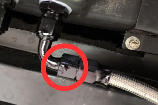
Identify Wet Spots: Look for any wet spots, drips, or stains around the fittings and connections, that indicate a leak.

Using Leak Detection Fluid

Apply Fluid: Spray or brush leak detection fluid around the suspected leak areas.

Observe: Watch for bubbles forming at the leak site. The fluid will react with escaping air or fluid, making the leak location more visible.

Pressure Testing

Repressurize the System: Carefully turn on the system and allow it to build pressure.

Monitor Pressure: Use a pressure gauge to monitor the system pressure. A pressure drop may indicate a leak.

Check for Leaks: While the system is under pressure, use the leak detection fluid again to check for leaks around the fittings.

Listen for Hissing: Sometimes, you can hear a hissing sound, which indicates escaping air or fluid from a leak.

Evaluate and Document Findings

Record Observations: Take notes of any leaks found, including their exact location and potential cause.

Photographic Evidence: Take photos of the leaks for reference and to assist with repairs.

Fixing AN Fitting Leaks

Fixing leaks in AN fittings involves several key steps, including reinstalling fittings, replacing worn or damaged fittings, ensuring a proper fit, and implementing regular maintenance and preventative measures. Each of these steps is crucial to maintaining the integrity and efficiency of your hydraulic or fluid system.  

Reinstalling Fittings

Detailed Instructions on How to Reinstall AN Fittings Correctly

Preparation:

Turn Off and Depressurize the System: Ensure the system is off and depressurized to avoid fluid or air escaping during reinstallation.

Clean the Area: Wipe down the fitting and surrounding area with a clean cloth to remove any debris or fluid residues.

Remove the Existing Fitting:

Use Appropriate Tools: Use a wrench or pliers to carefully loosen and remove the existing fitting. Take care not to damage the fitting or surrounding components.

Inspect the Threads and Sealing Surface: Check for any damage or wear on the threads and sealing surfaces of both the fitting and the connection point.

Install the New Fitting:

Apply Lubricant: Lightly lubricate the threads of the fitting with a suitable lubricant to ensure smooth installation and prevent galling.

Align the Fitting: Carefully align the fitting with the connection point to ensure a proper fit.

Hand-Tighten: Start by hand-tightening the fitting to avoid cross-threading.

Use a Torque Wrench: Finish tightening the fitting with a torque wrench to the manufacturer’s specified torque value. This ensures the fitting is neither over-tightened nor under-tightened.

Common Pitfalls to Avoid During Reinstallation:

Over-Tightening: Can damage threads and sealing surfaces, leading to leaks.

Under-Tightening: May result in insufficient sealing pressure, causing leaks.

Cross-Threading: Misaligned threads can damage both the fitting and the connection point, leading to leaks and difficulty in achieving a proper seal.

AN Fitting Leaking check

Replacing Worn or Damaged Fittings

How to Safely Remove and Replace Worn or Damaged Fittings

Turn Off and Depressurize the System: Ensure the system is safe to work on by turning it off and releasing any pressure.

Remove the Damaged Fitting:

Use Appropriate Tools: Use a wrench or pliers to carefully loosen and remove the damaged fitting.

Inspect the Connection Point: Check for any signs of damage or wear at the connection point. Clean the area thoroughly.

Select a Replacement Fitting:

Match the Size and Type: Ensure the replacement fitting matches the size and type of the original fitting.

Choose High-Quality Parts: Opt for high-quality fittings from reputable manufacturers to ensure durability and reliability.

Install the Replacement Fitting:

Apply Lubricant: Lightly lubricate the threads of the new fitting.

Align and Hand-Tighten: Align the fitting with the connection point and hand-tighten to avoid cross-threading.

Torque to Specifications: Use a torque wrench to tighten the fitting to the manufacturer’s specifications.

Ensuring Proper Fit

Methods to Ensure a Secure and Proper Fit

Correct Sizing:

Measure Accurately: Use precise measuring tools to ensure the fitting size matches the connection point.

Check Manufacturer Specifications: Refer to manufacturer guidelines to confirm the correct size and type of fitting.

Alignment:

Proper Alignment: Ensure the fitting is perfectly aligned with the connection point to prevent cross-threading and ensure a proper seal.

Use Alignment Tools: Utilize alignment tools if necessary to achieve correct alignment.

Tightening:

Hand-Tighten First: Begin by hand-tightening the fitting to prevent cross-threading.

Torque to Specifications: Finish tightening with a torque wrench to the specified torque value.

Maintenance and Preventative Measures

Routine Maintenance Tips to Prevent Future Leaks

Regular Inspections:

Visual Checks: Routinely inspect fittings for signs of wear, corrosion, or damage.

Pressure Testing: Conduct regular pressure tests to ensure the system maintains its integrity.

Cleaning:

Remove Debris: Keep fittings and surrounding areas clean to prevent contaminants from affecting the seal.

Use Protective Caps: Cover unused fittings with protective caps to prevent dirt and debris from entering.

Lubrication:

Apply Lubricant During Installation: Use appropriate lubricants on threads during installation to ensure smooth tightening and prevent damage.

Sealing:

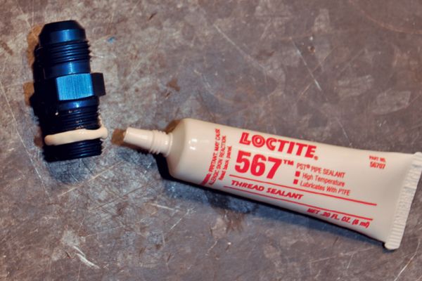
Thread Sealant: Use thread sealant or tape on threaded connections to enhance the seal and prevent leaks.

Use of Lubricants and Sealants:

Thread Lubricants: Apply thread lubricants to reduce friction and prevent galling during installation.

Sealants: Use thread sealants or tape to enhance the seal on threaded connections and prevent leaks.

By following these detailed steps for reinstalling, replacing, and maintaining AN fittings, you can effectively prevent leaks and ensure the long-term reliability and efficiency of your hydraulic or fluid systems. Proper installation, routine maintenance, and the use of high-quality components are key to maintaining leak-free AN fittings.

Conclusion

By adhering to best practices, using high-quality components, and conducting regular inspections, you can significantly reduce the risk of leaks and ensure the longevity and reliability of your systems. Taking these preventative measures not only enhances system performance but also minimizes downtime and maintenance costs. Follow these guidelines diligently to keep your AN fittings leak-free and your operations running smoothly.

FAQ

Signs of a leak include visible fluid around the fitting, a drop in system pressure, or the presence of bubbles when using leak detection fluid.

Essential tools include a wrench, torque wrench, inspection mirror, flashlight, leak detection fluid, and a clean cloth.

Yes, over-tightening can damage the fitting or sealing surface, leading to leaks.

It’s recommended to inspect AN fittings regularly, such as during routine maintenance checks or whenever the system is serviced.

Replace the worn or damaged fitting with a high-quality replacement that matches the size and specifications of the original.

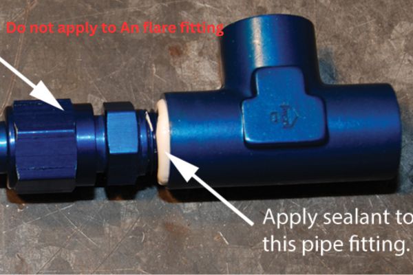
Thread sealants can be used on non-flared threaded connections to enhance the seal and prevent leaks. Always follow manufacturer recommendations.

How to Measure AN Fittings

How to Measure AN Fittings

How to Measure AN Fittings?

Table of Contents

Introduction

Precise measurements are crucial in hydraulic and automotive applications, ensuring optimal performance, safety, and compatibility. This guide aims to help readers accurately measure AN fittings, providing detailed instructions and tips to avoid common mistakes. By following this guide, readers can ensure compatibility and maintain the integrity of their hydraulic and automotive systems.

Understanding AN Fittings

Components of AN Fittings

AN fittings consist of several key components, each playing a vital role in their functionality. The primary parts are the male and female connectors, which interlock to create a secure connection. The male connector typically has an external thread, while the female connector has an internal thread that fits over the male end. Additionally, AN fittings feature a flared design, usually at a 37-degree angle, which ensures a tight seal when the male and female connectors are joined. These fittings are made from various materials, including aluminum, stainless steel, and brass, each chosen for its durability and resistance to corrosion. The finishes can range from anodized coatings to enhance corrosion resistance to polished surfaces for aesthetic purposes.

Types of AN Fittings

AN fittings are designed to meet various needs and applications, offering flexibility and reliability in high-pressure environments. Understanding the different types of AN fittings is crucial for selecting the right component for your specific requirements. Here’s an in-depth look at the various types of AN fittings:

AN hydraulic fittings Topa China manufacturer

37-Degree Flare Fittings

The 37-degree flare fitting is the most common type of AN fitting. It is widely used in high-pressure hydraulic systems and automotive fuel lines due to its robust design and reliable sealing capabilities. The 37-degree flare ensures a tight seal when connected, preventing leaks and maintaining system integrity under high pressure. These fittings come in multiple sizes, denoted by dash numbers such as -4, -6, -8, etc. These dash numbers correspond to the outside diameter of the tubing they are designed to fit, with each size serving different flow requirements and applications.

Elbow Fittings

Elbow fittings are used to change the direction of fluid flow within a system. Available in various angles such as 45 degrees and 90 degrees, elbow fittings are essential for routing hoses and tubing around obstacles or within confined spaces. These fittings help in optimizing the layout of hydraulic or fuel systems by providing smooth directional changes, which reduces the risk of kinks and flow restrictions.

Tee Fittings

Tee fittings allow for branching off fluid lines from a mainline, providing a way to split the flow into two separate paths. These fittings are particularly useful in complex systems where multiple components need to be connected to a single source. Tee fittings come in different configurations, such as equal tees where all three branches are of the same size, and reducing tees where one or more branches are of a different size.

Union Fittings

Union fittings are designed to connect two sections of tubing or hose, allowing for easy disconnection and reconnection without disturbing the rest of the system. These fittings are especially useful for maintenance and repair, as they provide a simple and effective way to replace or service individual components without having to dismantle the entire system.

Bulkhead Fittings

Bulkhead fittings are used to pass a fluid line through a panel or bulkhead. These fittings provide a secure and leak-proof connection point, allowing hoses or tubing to pass through walls or partitions while maintaining the integrity of the connection. Bulkhead fittings are commonly used in fuel systems and hydraulic applications where fluid lines need to be routed through different compartments.

Swivel Fittings

Swivel fittings are designed to allow rotation between the fitting and the hose or tubing it is connected to. This rotation capability helps prevent twisting and kinking of the hose, providing flexibility in installation and use.  

Identification Codes and Markings

AN fittings are marked with identification codes that provide essential information about their specifications. These codes typically include the fitting size, material, and manufacturer. For example, a fitting might be marked as AN6-304, indicating a size -6 fitting made from 304 stainless steel. Understanding these markings is crucial for selecting the correct fittings for your application. Additionally, some fittings may have color-coded anodized finishes to help identify their material or size at a glance. Familiarity with these codes and markings ensures you can quickly and accurately determine the right fitting for your needs, avoiding potential mismatches and ensuring system compatibility.

Tools Required for Measuring AN Fittings

Calipers

Calipers are essential for measuring the outside and inside diameters of AN fittings with high precision. They come in various types, such as digital, dial, and vernier calipers, each offering different levels of accuracy and ease of use.

Rulers and Measuring Tapes

These are useful for quick and rough measurements. Rulers are great for measuring lengths and straight edges while measuring tapes are ideal for flexible measurements around curved surfaces or tubing.

Thread Pitch Gauges

Thread pitch gauges are used to determine the thread pitch of the fittings. They help identify the number of threads per inch or the distance between threads, which is crucial for ensuring compatibility with other components.

AN Fitting Gauges

These gauges are specifically designed to measure the angle and flare of AN fittings. They ensure that the fittings meet the 37-degree standard and help in verifying the correct flare dimensions.

Digital Measuring Tools

Digital micrometers and other digital measuring instruments provide precise measurements and are especially useful for detailed inspections. They often come with features like digital readouts, which make it easier to obtain and record measurements accurately.

hydraulic fittings measure tools Topa

Step-by-Step Guide to Measuring AN Fittings

Measuring the Diameter

Internal and External Diameter Measurement Techniques

To measure the external diameter of an AN fitting, use a caliper. Open the caliper jaws and place them around the widest part of the fitting, ensuring a snug fit. Read the measurement from the caliper scale or digital readout. For internal diameter measurement, insert the caliper’s internal measuring jaws into the fitting’s opening. Expand the jaws until they touch the inner walls of the fitting and note the measurement.

It’s essential to measure at multiple points around the fitting to ensure consistency and accuracy, as imperfections or irregularities can lead to erroneous readings.

Importance of Precision and Consistency

Precision in measuring diameters ensures that the fittings will match correctly with other components, preventing leaks and failures. Consistent measurements, taken from multiple points and averaged if necessary, provide a reliable basis for selecting and using the fittings. This consistency helps in maintaining the integrity of the hydraulic or automotive system, ensuring safe and efficient operation.

Measuring the Thread Size

Using Thread Pitch Gauges

Thread pitch gauges are used to determine the thread pitch of AN fittings, which is the distance between threads or the number of threads per inch. Select a gauge with a thread profile that matches the fitting’s threads. Gently fit the gauge into the threads of the fitting. If it fits snugly without gaps or overlaps, you have found the correct pitch. Repeat the process with different gauges if necessary to confirm the pitch.

Identifying Fine vs. Coarse Threads

AN fittings typically use fine threads, but it’s crucial to identify this correctly. Fine threads have a higher number of threads per inch compared to coarse threads. Using a thread pitch gauge, count the number of threads over a specific distance, usually one inch. Fine threads will have a greater count, providing a tighter and more secure connection. Accurate identification of thread type ensures compatibility and prevents issues such as stripping or cross-threading.

Measure AN Fittings size

Measuring the Flare Angle

Tools and Methods for Accurate Flare Angle Measurement

The flare angle is a critical aspect of AN fittings, typically set at 37 degrees. To measure this angle accurately, use an AN fitting gauge designed specifically for this purpose. Place the fitting into the gauge and check if it aligns perfectly with the 37-degree mark. Alternatively, you can use a protractor or an angle finder tool. Place the tool against the flare and read the angle measurement. Ensure the tool is properly calibrated for precise readings.

Common Mistakes to Avoid

Accurate measurement of AN fittings is crucial for ensuring proper function and compatibility within hydraulic and automotive systems. Here are some common mistakes to avoid, ensuring your measurements are reliable and precise:

Using Worn or Damaged Tools

Measurement tools that are worn out or damaged can yield inaccurate results, leading to improper fitting selections and potential system failures. Regularly inspect your calipers, rulers, thread pitch gauges, and any other measuring tools for signs of wear, rust, or damage. Replace any tools that show significant wear or are damaged. Regular maintenance and proper storage of tools will help maintain their accuracy and extend their lifespan.

Measuring Dirty or Contaminated Fittings

Dirt, grease, and debris can affect the accuracy of your measurements. Before taking any measurements, thoroughly clean the fittings using appropriate cleaning agents and tools. Ensure all residues are removed, especially from the threads and flared areas. This will help achieve a more accurate measurement and prevent contaminants from affecting the fit and seal of the components when installed.

Assuming the Flare Angle

One of the most critical aspects of measuring AN fittings is confirming the flare angle. While most AN fittings use a 37-degree flare, never assume this to be the case without measuring. Use an AN fitting gauge or a protractor to verify the flare angle precisely. Incorrect assumptions about the flare angle can lead to mismatched components, leaks, and potential system failures. Always measure to confirm the exact angle.

Inconsistent Measurement Techniques

Consistency in measurement techniques is key to obtaining reliable data. When measuring diameters or thread pitches, ensure you take multiple measurements at different points around the fitting. Averaging these measurements can provide a more accurate result. Inconsistent measuring techniques can lead to errors and affect the integrity of the entire system.

Ignoring Calibration and Tool Accuracy

Measurement tools should be regularly calibrated to maintain their accuracy. Ignoring calibration can result in tools providing incorrect measurements, which can lead to improper fitting selection. Follow the manufacturer’s guidelines for calibration frequency and procedures. Calibration ensures that your tools remain accurate and reliable over time.

Overlooking the Importance of Double-Checking

Double-checking your measurements can prevent many common errors. After taking initial measurements, repeat the process to confirm the results. This practice helps catch any mistakes or inconsistencies and ensures that your measurements are precise. Taking the extra time to double-check can save significant time and resources by preventing the use of incorrect fittings.

Selecting the Most Suitable AN Fitting

Choosing the right AN fitting for your application is critical to ensuring the efficiency, safety, and reliability of your hydraulic or automotive systems. The selection process involves several key considerations to match the fitting to your specific requirements. Here’s a comprehensive guide on how to select the most suitable AN fitting:

Determine the Application Requirements

Pressure Rating: Identify the maximum pressure your system will be operating under. AN fittings are rated for high-pressure applications, but ensuring the fitting’s pressure rating matches your system’s requirements is essential to prevent leaks and failures.

Fluid Type: Consider the type of fluid that will flow through the fittings. Different materials are compatible with different fluids. For instance, aluminum fittings are lightweight and resistant to corrosion from petroleum-based fluids, while stainless steel fittings offer higher strength and resistance to corrosive fluids.

Temperature Range: Evaluate the temperature conditions the fittings will be exposed to. Some materials perform better in high-temperature environments, while others may become brittle or degrade over time.

Select the Appropriate Fitting Size

Dash Numbers: AN fittings are denoted by dash numbers (e.g., -4, -6, -8) which represent the size of the fitting. The dash number corresponds to the outside diameter of the tubing in sixteenths of an inch. For example, a -6 fitting is designed for tubing with a 3/8-inch outside diameter.

Tubing Compatibility: Ensure the fitting size matches the tubing or hose size in your system. Using mismatched sizes can lead to poor sealing and potential leaks.

Choose the Right Material

Aluminum: Lightweight and corrosion-resistant, suitable for most automotive and general-purpose applications.

Stainless Steel: Offers superior strength and corrosion resistance, ideal for high-pressure and harsh environments.

Brass: Provides good corrosion resistance and machinability, commonly used in lower-pressure applications.

Composite Materials: Sometimes used for specific applications where weight savings and corrosion resistance are critical.

Evaluate Environmental Factors

Exposure to Elements: Consider environmental conditions such as exposure to chemicals, moisture, and UV light. Choose materials and finishes that can withstand these conditions.

Vibration and Movement: In applications subject to vibration or movement, opt for fittings with features like swivels to accommodate motion without compromising the connection.

Conclusion

In this comprehensive guide, we’ve covered the essential steps and tips for measuring AN fittings accurately. Precise measurements lead to better fitting selection, proper installation, and ultimately, a well-functioning system.  We encourage you to practice and refine your measurement skills regularly. Familiarize yourself with the tools and techniques discussed in this guide, and don’t hesitate to double-check your work to ensure accuracy.

FAQ

The dash number in AN fittings corresponds to the outside diameter of the tubing in sixteenths of an inch. For example, a -4 fitting is designed for tubing with a 1/4-inch outside diameter.

AN fittings use UNF (Unified Fine Thread) and are not directly compatible with NPT (National Pipe Thread) fittings. However, you can use adapters to connect AN fittings to NPT threads.

To ensure accurate measurements, use calibrated tools, clean the fittings thoroughly before measuring, and double-check your measurements. Taking multiple measurements at different points can also help confirm accuracy.

The material choice depends on your application. Aluminum is lightweight and corrosion-resistant, stainless steel offers high strength and resistance to corrosive environments, and brass is suitable for lower-pressure applications.

The common flare angle for AN fittings is 37 degrees. This angle is crucial for ensuring a proper seal and preventing leaks in high-pressure applications.

Double-checking the flare angle ensures compatibility and prevents mismatched components, which can lead to leaks and system failures. Always measure to confirm the angle rather than assuming it is correct.

Contact Topa

Have a question or suggestion? Fill out the form below to get in touch with one of our experts.

Do AN Fittings Need Sealant

Do AN Fittings Need Sealant?

Do AN Fittings Need Sealant?

Introduction

AN fittings are specialized connectors used extensively in hydraulic systems to ensure secure and leak-free connections. These fittings, known for their durability and precision, play a critical role in various industries, including automotive, aerospace, and industrial hydraulics. Proper sealing in hydraulic systems is paramount to prevent leaks, which can lead to system inefficiencies, safety hazards, and costly downtime. This article aims to address a common question among industry professionals: Do AN fittings need sealant?

The Role of Sealant in Hydraulic Fittings

Sealants play a crucial role in hydraulic systems by addressing two primary needs: preventing leaks and enhancing connection strength. Leaks in hydraulic systems can cause significant issues, including loss of pressure, reduced efficiency, potential damage to equipment, and safety hazards. By using sealants, connections are fortified against the risk of leakage, ensuring the system operates smoothly and efficiently. Additionally, sealants can improve the overall strength of the connections, providing extra security in high-pressure environments and preventing fittings from loosening due to vibrations or thermal expansion.

Types of Sealants

There are several types of sealants used in hydraulic systems, each serving specific purposes:

Thread Sealant (Liquid and Tape): Liquid thread sealants are applied directly to the threads before assembly, creating a tight seal as they cure. Teflon tape, a common thread sealant, is wrapped around the threads to fill any gaps and create a seal when the fitting is tightened.

O-rings and Gaskets: These are pre-formed seals made from materials such as rubber, silicone, or metal. They are placed between mating surfaces to prevent leaks. O-rings are commonly used in static and dynamic sealing applications, while gaskets are typically used in static applications.

How Sealants Work

Sealants function through two main mechanisms:

Chemical Bonding: Certain liquid sealants cure through a chemical reaction, forming a solid, durable bond that fills any gaps between threads or surfaces. This chemical bond provides a robust seal that resists pressure, temperature changes, and chemical exposure.

Physical Barrier: Sealants like Teflon tape and O-rings create a physical barrier that blocks the passage of fluids. Teflon tape fills the space between threads, while O-rings and gaskets compress to fill gaps, preventing fluid from escaping.

Do AN Fittings Need Sealant?

Do not apply to An flare fitting

AN fittings are engineered with a unique seal design that typically eliminates the need for additional sealants. The sealing mechanism in AN fittings relies on two main features:

Flare and Cone Interface: AN fittings utilize a 37-degree flare at the end of the tubing that mates with a corresponding cone-shaped seat within the fitting. When tightened, the flare and cone interface creates a secure, leak-proof metal-to-metal seal. This design ensures that the seal is maintained under high pressure without the need for extra sealants.

Metal-to-Metal Seal: The precision-engineered metal surfaces of AN fittings are designed to mate perfectly, forming a tight seal that is both robust and reliable. This metal-to-metal contact eliminates the gaps and spaces that could otherwise lead to leaks, making sealants unnecessary in most cases.

Factors to Consider

Application-Specific Requirements

When deciding whether AN fittings need sealant, it’s crucial to consider the specific requirements of the application, including:

High-Pressure vs. Low-Pressure Systems: In high-pressure hydraulic systems, the integrity of the seal is paramount. AN fittings are designed to handle high pressures without additional sealant, relying on their metal-to-metal seal. In low-pressure systems, the need for sealant might be less critical, but the robust design of AN fittings still generally negates the necessity for sealant.

Temperature Extremes: Hydraulic systems operating under extreme temperatures require reliable seals that can withstand thermal expansion and contraction. AN fittings’ metal-to-metal seals are effective across a wide range of temperatures, making them suitable for use without sealants in both hot and cold environments.

Material Compatibility

The materials used for AN fittings and their compatibility with the hydraulic fluid and the system’s environment are also important factors:

Aluminum, Steel, Stainless Steel AN Fittings: The choice of material for AN fittings can affect their performance in different environments. Aluminum fittings are lightweight and corrosion-resistant, making them ideal for applications where weight is a concern. Steel fittings offer high strength and are suitable for high-pressure applications, while stainless steel fittings provide excellent corrosion resistance in harsh environments.

Chemical Resistance and Reactivity: It’s important to ensure that the material of the AN fittings is compatible with the hydraulic fluid and any other chemicals in the system. Incompatible materials can lead to corrosion, leaks, and system failure. Sealants, if used, should also be compatible with both the fittings and the fluid to avoid chemical reactions that could compromise the seal.

Installation Best Practices

Proper installation techniques are critical to ensuring the reliability of AN fittings without the need for sealants:

Proper Torque Specifications: Applying the correct torque during installation is essential to achieve a secure metal-to-metal seal. Over-tightening or under-tightening can lead to leaks and fitting failure. Manufacturer guidelines should be followed to ensure the correct torque is applied.

Avoiding Over-Tightening: Over-tightening AN fittings can damage the sealing surfaces, compromising the integrity of the metal-to-metal seal. It’s important to follow best practices, such as using a torque wrench and adhering to specified torque values, to avoid over-tightening.

By considering these factors—application-specific requirements, material compatibility, and installation best practices—professionals can ensure that AN fittings perform reliably without the need for additional sealants.

Alternatives to Sealant

Using AN Fittings Without Sealant

AN fittings are designed to provide a reliable seal without the need for additional sealants. Here are some scenarios where the sealant is unnecessary and the associated benefits and potential drawbacks:

Scenarios Where Sealant is Unnecessary:

Standard Hydraulic Systems: In typical hydraulic applications where AN fittings are properly installed and maintained, the metal-to-metal seal provided by the flare and cone interface is usually sufficient to prevent leaks.

High-Pressure Applications: AN fittings are specifically designed to handle high-pressure environments, making them suitable for use without sealant in systems where maintaining pressure integrity is crucial.

Temperature-Variable Environments: The precision engineering of AN fittings ensures that they can maintain a reliable seal even under temperature fluctuations, eliminating the need for additional sealant.

Benefits and Potential Drawbacks

Benefits:

Leak Prevention: The metal-to-metal seal of AN fittings is highly effective at preventing leaks without the need for sealant, reducing maintenance and downtime.

Durability: AN fittings are less likely to degrade or fail over time compared to seals reliant on chemical sealants, which can wear out or become ineffective.

Simplified Maintenance: Without the need for sealant, installation, and maintenance become simpler and cleaner, avoiding the mess and potential for contamination that sealants can cause.

Potential Drawbacks:

Initial Installation Precision: Achieving a leak-free seal with AN fittings requires precise installation. Any damage to the sealing surfaces or improper torque can lead to leaks.

Potential for Misapplication: In some cases, users might mistakenly apply sealant, thinking it will enhance the seal, which can cause issues such as contamination or improper fitting seating.

Ensuring a Proper Seal Without Sealant

To ensure a reliable seal using AN fittings without the need for sealant, it’s important to focus on proper installation practices:

Importance of Clean and Undamaged Threads:

Clean Threads: Before installation, make sure that all threads are clean and free from debris, dirt, or old sealant residue. Contaminants can prevent proper seating of the flare and cone, leading to leaks.

Undamaged Threads: Inspect the threads for any damage, such as nicks, burrs, or deformities. Damaged threads can compromise the integrity of the seal. If threads are damaged, it’s best to replace the fitting or tubing end.

Correct Installation Techniques:

Proper Torque Application: Use a torque wrench to apply the correct amount of torque as specified by the manufacturer. Over-tightening or under-tightening can cause leaks or damage the fitting.

Aligning Fittings Properly: Ensure that the tubing and fitting are properly aligned before tightening. Misalignment can prevent the flare and cone from seating correctly, leading to an incomplete seal.

Avoid Over-Tightening: Over-tightening can deform the sealing surfaces, leading to leaks. Follow manufacturer guidelines and use a torque wrench to avoid this common mistake.

How to Use Sealant for AN Fittings

While AN fittings are designed to create a reliable seal without additional sealants, there are instances where using a sealant might be considered. If you choose to use sealant, it’s crucial to apply it correctly to ensure the integrity of the fitting. Here is a detailed guide on how to use sealant for AN fittings:

Choose the Right Sealant

Thread Sealant: Use a thread sealant that is compatible with the materials of your fittings and the fluids in your system. Liquid thread sealants are often preferred for their ease of use and reliability.

Teflon Tape: If you opt for Teflon tape, make sure it is designed for hydraulic systems and compatible with the materials and fluids used.

AN Fittings Sealant

Prepare the Fittings

Clean the Threads: Ensure the threads of both the fitting and the tubing are clean and free from any debris, dirt, or old sealant. Use a brush or cloth to remove any contaminants.

Inspect for Damage: Check the threads for any signs of damage, such as nicks, burrs, or deformities. Damaged threads should be replaced to ensure a proper seal.

Applying Liquid Thread Sealant

Apply Evenly: Apply a small amount of liquid thread sealant to the male threads of the AN fitting. Spread it evenly around the threads, avoiding excess sealant that could contaminate the system.

Avoid the First Thread: Leave the first thread or two free of sealant to ensure that excess sealant does not enter the hydraulic system.

Allow to Cure: Follow the manufacturer’s instructions regarding curing time. Some sealants require a certain amount of time to set before the system can be pressurized.

Applying Teflon Tape

Wrap the Tape: Begin wrapping the Teflon tape around the male threads, starting from the second thread. Wrap in the direction of the threads (usually clockwise) to ensure the tape doesn’t unravel when the fitting is tightened.

Ensure Coverage: Wrap the tape around the threads 2-3 times, ensuring it covers the threads completely but does not create a bulky layer.

Press and Smooth: Press the tape into the threads to smooth it out and ensure it adheres well.

Assembling the Fittings

Align Properly: Align the fitting and the tubing correctly before starting to tighten. Proper alignment is crucial to avoid cross-threading and ensure a good seal.

Tighten to Specification: Use a torque wrench to tighten the fitting to the manufacturer’s specified torque. Over-tightening can damage the fitting and compromise the seal, while under-tightening can lead to leaks.

Check for Leaks: After assembly, pressurize the system and check for leaks. If leaks are detected, re-tighten the fittings slightly and recheck. If leaks persist, disassemble, reapply sealant, and reassemble.

Tips and Best Practices

Follow Manufacturer Instructions: Always follow the sealant manufacturer’s instructions for application and curing. Different products have specific requirements.

Avoid Overuse: Use only the necessary amount of sealant. Excessive use can lead to contamination and other issues.

Regular Inspection: Regularly inspect fittings for signs of leaks or wear. Reapply sealant as needed during routine maintenance.

Avoid These Mistakes When Using Sealant with AN Fittings

While applying sealant to AN fittings can be beneficial in certain situations, it’s crucial to avoid common mistakes that can compromise the integrity of the fitting and the hydraulic system. Here are key mistakes to avoid:

Using Sealant When Not Needed

Unnecessary Application: AN fittings are designed to create a reliable metal-to-metal seal without additional sealants. Applying sealant when it’s not required can lead to contamination and improper sealing.

Manufacturer Guidelines: Always refer to the manufacturer’s recommendations. Many AN fitting producers advise against using sealants on their products.

Over-Tightening the Fittings

Damage to Sealing Surfaces: Over-tightening can deform the sealing surfaces of the flare and cone, leading to leaks and potential fitting failure.

Proper Torque: Use a torque wrench to apply the correct amount of torque as specified by the manufacturer to avoid over-tightening.

Applying Too Much Sealant

Excess Sealant: Using too much liquid sealant or wrapping too many layers of Teflon tape can cause the sealant to squeeze into the hydraulic system, leading to contamination and blockages.

Even Application: Apply a thin, even layer of liquid sealant or 2-3 wraps of Teflon tape to ensure proper sealing without excess material.

Incorrect Sealant Selection

Compatibility Issues: Not all sealants are suitable for use with hydraulic systems or compatible with the materials of the fittings and the hydraulic fluid.

Right Product: Choose a sealant specifically designed for hydraulic systems and ensure it is compatible with the materials and fluids involved.

Not Allowing Sealant to Cure

Premature Pressurization: Some liquid thread sealants require a curing period to form a proper bond. Pressurizing the system before the sealant has cured can result in leaks.

Curing Time: Follow the manufacturer’s instructions regarding the required curing time before pressurizing the system.

Incorrect Tape Wrapping

Wrong Direction: Wrapping Teflon tape in the wrong direction can cause it to unravel when the fitting is tightened.

Proper Technique: Wrap the tape in the direction of the threads (usually clockwise) to ensure it stays in place during assembly.

Conclusion

In summary, AN fittings are meticulously designed to create a reliable metal-to-metal seal, which typically negates the need for additional sealants. However, understanding when and how to use sealant correctly can be beneficial in specific scenarios. Following best practices, such as ensuring clean and undamaged threads, applying the correct torque, and choosing the right sealant, can enhance the reliability and efficiency of hydraulic systems.  

FAQ

AN fittings typically do not require sealant because they are designed to create a reliable metal-to-metal seal. However, in some cases, a thread sealant can be used if recommended by the manufacturer.

If sealant is necessary, use a compatible liquid thread sealant or Teflon tape designed for hydraulic systems. Ensure it is suitable for the materials and fluids in your application.

Yes, over-tightening can damage the sealing surfaces, leading to leaks. Always use a torque wrench and follow the manufacturer’s specified torque values to avoid over-tightening.

Check for proper alignment, ensure the threads are clean and undamaged, and verify that the fitting is tightened to the correct torque. If leaks persist, disassemble, clean, and reapply sealant if necessary, then reassemble correctly.

Wrap Teflon tape around the male threads 2-3 times, starting from the second thread, and wrap in the direction of the threads (usually clockwise) to ensure it stays in place during tightening.

Using excessive sealant can lead to contamination and improper sealing. Apply a thin, even layer of liquid sealant or a moderate amount of Teflon tape to achieve a proper seal without excess material.

An Fitting Install Troubleshooting Common Issues

An Fitting Install: Troubleshooting Common Issues

An Fitting Install: Troubleshooting Common Issues

Table of Contents

Introduction

AN fittings, known for their durability and precision, are commonly used in various applications such as automotive, aerospace, and industrial machinery. These fittings ensure secure, leak-free connections that are essential for system efficiency and safety. However, improper installation can lead to misalignment, leaks, and system failures. Troubleshooting and resolving common issues promptly can prevent costly downtime and potential hazards. This post aims to provide readers with valuable insights and practical solutions for addressing common installation problems, ultimately enhancing the reliability and longevity of their hydraulic systems.

Understanding AN Fittings

AN (Army-Navy) fittings are standardized connectors used primarily in fluid transfer systems. They feature a 37-degree flare fitting, designed to provide a secure and reliable connection. AN fittings come in various sizes, typically designated by a dash number indicating the size in 1/16-inch increments (e.g., -4, -6, -8). Common types of AN fittings include straight, elbow, tee, and bulkhead fittings, each designed for specific routing and connection needs.

Materials and Specifications

AN fittings are commonly made from high-quality materials such as aluminum, stainless steel, and brass. Aluminum fittings are lightweight and corrosion-resistant, making them ideal for automotive and aerospace applications. Stainless steel fittings offer superior strength and durability, suitable for high-pressure and high-temperature environments. Brass fittings provide good corrosion resistance and are often used in plumbing and general industrial applications. Specifications for AN fittings include precise thread dimensions, material grades, and pressure ratings, ensuring they meet the rigorous demands of various systems.

Common Uses and Benefits of AN Fittings

AN fittings are widely used in industries where the reliable fluid transfer is critical. In the automotive industry, they are used for fuel, brake, and oil lines due to their high-performance capabilities and ease of installation. In aerospace, AN fittings are essential for hydraulic and fuel systems, ensuring safe and efficient aircraft operation. Industrial machinery and equipment also rely on AN fittings for hydraulic and pneumatic systems, benefiting from their durability and leak-proof connections. The key benefits of AN fittings include their high pressure and temperature tolerance, ease of assembly and disassembly, and the ability to create custom configurations for specific applications.

Step-by-Step Installation Guide

Cutting the Hose

Measure the Required Length

Begin by accurately measuring the required length of the hose or tube. Use a tape measure or ruler to ensure precision. Mark the hose with a marker or tape to indicate where the cut will be made.

Cut the Hose

Use a high-quality tube cutter or hacksaw to cut the hose at the marked location. Ensure the cut is clean and straight to avoid any sealing issues later. A straight cut ensures a uniform contact surface for the fitting.

For best results, use a tube cutter designed for the specific type of hose material (e.g., rubber, PTFE, or stainless steel braided). This helps maintain the integrity of the hose and ensures a clean cut.

cut rubber hose

Deburring the Hose

Remove Sharp Edges

After cutting the hose, use a deburring tool to remove any sharp edges or burrs from the cut end. Burrs can interfere with the fitting assembly and may cause leaks or damage to the fitting.

Carefully run the deburring tool around the inside and outside edges of the hose to create a smooth, clean surface. This step is crucial for ensuring a secure fit with the AN fitting.

Inspect the Hose

After deburring, visually inspect the hose end to ensure all burrs and sharp edges have been removed. The hose end should be smooth and even and ready for fitting installation.

Installing the Hose End

Slide the Fitting Nut and Sleeve

Slide the AN fitting nut onto the hose, followed by the sleeve (or ferrule). Ensure the sleeve is oriented correctly according to the fitting type. The sleeve is designed to create a tight seal when the fitting is assembled.

For braided hoses, take extra care to ensure the braid is evenly distributed around the fitting body. This helps achieve a secure and uniform seal.

Insert the Hose into the Fitting Body

Insert the hose into the fitting body until it bottoms out. Ensure the hose is fully seated within the fitting body to create a proper seal.

For hoses with a braided cover, ensure the braid is not obstructing the fitting body and is properly aligned.

Securing the Fitting

Lubricate the Threads

Lubricate the threads of the fitting and nut with a compatible lubricant. This reduces friction during assembly and helps prevent galling or thread damage.

Use a lubricant that is compatible with the hose and fitting materials as well as the fluid type used in the system.

Hand-Tighten the Nut

Hand-tighten the nut onto the fitting body. This initial tightening helps ensure the fitting components are properly aligned before using a wrench.

Secure the Fitting in a Vice

Place the fitting into a vice with soft jaws to avoid damaging the fitting surface. Soft jaws provide a secure grip without marring the fitting.

Tighten the Nut with a Wrench

Use a wrench to tighten the nut onto the fitting body. Follow the manufacturer’s recommended torque specifications to avoid over-tightening, which can cause damage or deformation to the fitting.

Tighten the nut until you feel a slight resistance, then give it an additional turn to ensure a secure fit. Do not over-tighten, as this can lead to issues such as stripped threads or crushed fittings.

An Fitting Install hydraulic hose

Common Installation Issues

Overview of Potential Problems During Installation

When installing AN fittings, various issues can arise that compromise the integrity and performance of the connections. Being aware of these common problems and understanding how to address them is crucial for ensuring a successful and leak-free installation. Below are some of the most frequent issues encountered during AN fitting installation:

Misalignment

Symptoms

Visible gaps between fitting components.

Uneven contact surfaces.

Difficulty in threading the nut onto the fitting body.

Causes

Incorrect hose cutting or deburring.

Improper insertion of the hose into the fitting body.

Misalignment of the fitting components before tightening.

Solutions

Ensure the hose is cut straight and deburred properly.

Carefully insert the hose into the fitting body until it bottoms out.

Align the fitting components correctly before tightening the nut.

Use a vice with soft jaws to hold the fitting securely while ensuring proper alignment.

Over-Tightening or Under-Tightening

Symptoms

Over-tightening: Stripped threads, crushed fitting components, or difficulty in disassembling the fitting.

Under-tightening: Loose connections, leaks, or components that can be moved by hand.

Causes

Not following the manufacturer’s torque specifications.

Using excessive force when tightening the nut.

Insufficient tightening, leads to a weak seal.

Solutions

Always use a torque wrench to achieve the recommended torque specifications.

Avoid using excessive force when tightening the fitting.

Double-check the tightness of the fitting to ensure it is secure but not over-tightened.

Cross-Threading

Symptoms

Difficulty in threading the nut onto the fitting body.

Visible damage to the threads.

Misalignment between the nut and fitting body.

Causes

Misalignment of the fitting components before threading.

Forcing the nut onto the fitting body at an incorrect angle.

Damaged or contaminated threads.

Solutions

Inspect the threads for damage or contamination before assembly.

Ensure proper alignment of the fitting components before threading.

Thread the nut onto the fitting body by hand initially to avoid cross-threading.

If cross-threading occurs, disassemble the fitting and inspect the threads. Repair or replace damaged threads as needed.

Inadequate Lubrication

Symptoms

Increased friction during assembly.

Difficulty in tightening the nut onto the fitting body.

Potential damage to the threads or fitting components.

Causes

Not using lubricant during assembly.

Using an incompatible lubricant.

Insufficient application of lubricant.

Solutions

Apply a compatible lubricant to the threads of the fitting and nut before assembly.

Ensure even distribution of the lubricant to reduce friction.

Reapply lubricant as needed during assembly to maintain smooth threading.

Contamination and Debris

Symptoms

Leaks or poor sealing performance.

Damage to the fitting components during assembly.

Blockages or obstructions in the fluid flow.

Causes

Contaminants or debris in the hose, fittings, or assembly area.

Inadequate cleaning of components before installation.

Failure to protect open ends of hoses or fittings during storage.

Solutions

Clean all components thoroughly before assembly to remove any contaminants or debris.

Use protective covers or caps to keep hoses and fittings clean during storage and handling.

Inspect the assembly area for cleanliness and ensure it is free from debris.

Troubleshooting Misalignment

Symptoms of Misalignment in AN Fittings

Visible Gaps: There are noticeable gaps between the fitting components.

Uneven Contact Surfaces: The surfaces of the fitting do not sit flush against each other.

Threading Difficulty: Difficulty in threading the nut onto the fitting body, indicating components are not aligned correctly.

Leaks: Presence of leaks at the connection point due to improper sealing.

Causes of Misalignment and How to Prevent It

Incorrect Hose Cutting: An uneven or angled cut can cause the hose to sit improperly in the fitting.

Prevention: Use a tube cutter or saw to make a clean, straight cut. Always deburr the cut ends.

Improper Insertion: The hose is not fully inserted into the fitting body.

Prevention: Ensure the hose is pushed fully into the fitting body until it bottoms out.

Component Misalignment: Fitting components are not aligned correctly before tightening.

Prevention: Align all components properly before threading the nut. Use visual and tactile checks to confirm alignment.

Step-by-Step Troubleshooting Guide

Identifying Misalignment

Visual Inspection:

Check the fitting for any visible gaps between components.

Ensure that all surfaces are flush and even.

Threading Test:

Try threading the nut onto the fitting body by hand. If it doesn’t thread smoothly, misalignment is likely.

Leak Check:

Pressurize the system and check for leaks around the fitting. Leaks often indicate misalignment.

Correcting the Angle and Ensuring Proper Alignment

An Fitting Install

Disassemble the Fitting:

Carefully disassemble the fitting by unscrewing the nut and separating the components.

Inspect Components:

Inspect the fitting components for any signs of damage or debris. Clean all parts thoroughly.

Align the Hose:

Reinsert the hose into the fitting body, ensuring it is fully seated and aligned correctly. For braided hoses, make sure the braid is evenly distributed.

Align the Components:

Place the fitting components together, ensuring they are aligned properly. The nut should easily engage the threads of the fitting body without force.

Reassembling the Fitting

Lubricate the Threads:

Apply a compatible lubricant to the threads of the fitting and the nut to facilitate smooth assembly.

Hand-Tighten the Nut:

Begin threading the nut onto the fitting body by hand. Ensure it threads smoothly without resistance, indicating proper alignment.

Secure the Fitting:

Place the fitting in a vice with soft jaws to prevent damage. Use a wrench to tighten the nut to the manufacturer’s specified torque.

Final Inspection:

Perform a final visual inspection to confirm there are no gaps and all components are flush.

Pressure Test:

Pressurize the system and check for leaks to ensure the fitting is properly aligned and secured

Preventing and Fixing Cross-Threading

Identifying Cross-Threading Issues

Symptoms:

Difficulty in threading the nut onto the fitting body.

Visible damage or deformation of the threads.

Misalignment between the nut and fitting body.

Resistance or binding when tightening the nut.

Causes of Cross-Threading During Installation

Misalignment: The fitting components are not properly aligned before threading.

Forcing the Nut: Applying excessive force to thread the nut onto the fitting body at an incorrect angle.

Damaged Threads: Pre-existing damage or debris on the threads.

Best Practices to Prevent Cross-Threading

Proper Alignment: Ensure all components are aligned correctly before threading.

Hand-Threading First: Always start threading the nut by hand to avoid applying excessive force.

Thread Inspection: Inspect threads for damage or debris before installation.

Importance of Lubrication

Role of Lubrication in AN Fitting Installation

Reducing Friction: Lubrication reduces friction between threads, making assembly easier and preventing thread damage.

Ensuring Proper Torque: Helps achieve the correct torque without over-tightening.

Preventing Galling: Protects threads from galling, which can cause permanent damage.

Types of Lubricants Suitable for AN Fittings

Anti-Seize Compounds: Suitable for preventing galling in metal-to-metal contact.

Hydraulic Oil: Compatible with the system’s fluid and materials.

Silicone-Based Lubricants: Offer good protection and compatibility with various materials.

Signs of Inadequate Lubrication

Increased Friction: Difficulty in tightening the nut onto the fitting body.

Thread Damage: Visible damage or galling on the threads.

Poor Sealing: Leaks due to improper torque application.

Managing Contamination and Debris

Common Sources of Contamination and Debris

Environmental Factors: Dust, dirt, and debris from the installation environment.

Handling: Contamination is introduced during handling and assembly.

Residual Manufacturing Debris: Particles left from the manufacturing process.

Impact of Contaminants on Fitting Performance

Leaks: Contaminants can prevent proper sealing, leading to leaks.

Damage: Debris can cause wear and damage to fitting components.

Flow Obstruction: Contaminants can block or restrict fluid flow, reducing system efficiency.

Preventive Measures to Keep Fittings Clean

Clean Work Area: Maintain a clean and organized work environment.

Protective Covers: Use caps or plugs to protect fitting ends during storage and handling.

Regular Cleaning: Clean fittings and tools regularly to prevent contamination.

Conclusion

In this post, we’ve covered the essential steps and best practices for installing AN fittings, including identifying and troubleshooting common issues such as misalignment, cross-threading, inadequate lubrication, and contamination. Proper installation and meticulous attention to these details are crucial to ensuring the reliability and performance of your hydraulic systems. By following the outlined procedures and preventive measures, you can achieve leak-free and durable connections. If you encounter any challenges or need further assistance, don’t hesitate to seek professional advice to ensure the optimal functioning of your system.

FAQ

AN fittings are primarily used in hydraulic systems for creating secure, leak-free connections. They are commonly found in automotive, aerospace, and industrial applications.

To prevent cross-threading, always start threading the nut onto the fitting body by hand, ensuring proper alignment. Avoid using excessive force and inspect the threads for damage or debris before installation.

Use a compatible lubricant such as anti-seize compounds, hydraulic oil, or silicone-based lubricants. Ensure the lubricant is suitable for the materials and fluid type used in your system.

Signs of misalignment include visible gaps between fitting components, uneven contact surfaces, and difficulty in threading the nut onto the fitting body. Misalignment can also lead to leaks.

Clean AN fittings with a clean, lint-free cloth to remove surface dirt. For stubborn contaminants, use a suitable solvent or cleaning solution, rinse thoroughly, and allow the fittings to dry completely before installation.

Proper torque ensures that the fitting is securely tightened without over-tightening, which can cause damage or deformation. Using a torque wrench to achieve the manufacturer’s recommended torque specifications helps maintain the integrity and performance of the connection.

NPTF Thread Meaning A Comprehensive Guide

NPTF Thread Meaning: A Comprehensive Guide

NPTF Thread Meaning: A Comprehensive Guide

Introduction

Among the various thread types, the National Pipe Taper Fuel (NPTF) thread stands out due to its unique design and sealing capabilities. Unlike standard threads, NPTF threads are engineered to create a dry seal without the need for additional sealants, making them particularly valuable in high-pressure environments.  

What is NPTF Thread?

Definition of NPTF Thread

The National Pipe Taper Fuel thread, also known as Dryseal American National Standard Taper Pipe Thread, is a specialized type of thread designed to provide a seal without the need for additional sealing compounds. The primary function of NPTF threads is to ensure leak-proof connections in hydraulic systems, fuel lines, and other high-pressure applications.

6404 SAE to NPTF adapter Topa

History and Development of NPTF Thread

NPTF threads were developed to address the limitations of the standard National Pipe Taper (NPT) threads, which often required additional sealants to achieve a leak-free connection. The evolution of NPTF threads was driven by the need for a more reliable and consistent sealing method in industries where leaks could lead to significant safety hazards or operational inefficiencies. Over time, the design and standards for NPTF threads have been refined to meet the rigorous demands of modern hydraulic and fuel systems.

Detailed Description of the Taper Angle

The taper angle of NPTF threads is a critical feature that distinguishes them from other thread types. NPTF threads have a taper angle of 1 degree, 47 minutes, which equates to a 3/4-inch taper per foot. This specific taper angle ensures that as the threads are tightened, they create a wedging action that results in a secure and leak-free seal. The taper angle allows for the threads to deform slightly under pressure, enhancing the sealing capability without the need for additional materials.

Differences Between NPT and NPTF Threads

While NPT and NPTF threads may appear similar at first glance, there are key differences in their design and application. NPT threads are designed primarily for mechanical joining and typically require the use of sealants such as Teflon tape or pipe dope to achieve a leak-proof seal. In contrast, NPTF threads are designed to create a seal through the metal-to-metal contact of the threads themselves, eliminating the need for additional sealing compounds. This makes NPTF threads particularly suitable for applications where cleanliness and reliability are paramount, such as in hydraulic and fuel systems.

Precision and Sealing Properties of NPTF Threads

NPTF threads are manufactured to higher precision standards than NPT threads. The precision in the thread form and the controlled interference fit between the male and female threads ensure that NPTF connections provide a reliable seal without additional sealants. This dry seal capability is achieved through the precise engagement of the thread flanks, which deform slightly to create a tight, leak-proof connection. The inherent sealing properties of NPTF threads make them ideal for applications where leakage could lead to safety hazards, contamination, or operational inefficiencies.

Materials Commonly Used for NPTF Threads

NPTF threads can be found in a variety of materials, each selected based on the specific requirements of the application. Common materials include stainless steel, brass, carbon steel, and various alloys. Stainless steel NPTF threads are often used in corrosive environments due to their resistance to rust and corrosion. Brass is commonly used in fuel and hydraulic applications for its excellent machinability and good sealing properties. Carbon steel is selected for its strength and durability in high-pressure applications. The choice of material depends on factors such as pressure, temperature, and the chemical nature of the fluids being handled.

NPTF Thread Standards and Specifications

NPTF threads are governed by a series of standards and specifications that ensure their proper design, manufacturing, and application. The most relevant standards include the ANSI/ASME B1.20.3, which details the dimensional and performance requirements for NPTF threads. This standard outlines the taper angle, thread form, pitch diameter, and other critical dimensions that must be adhered to for the threads to function correctly. Adherence to these standards ensures that NPTF threads can provide the necessary sealing properties and maintain consistency across different manufacturers and applications.

Explanation of How These Standards Ensure Quality and Compatibility

Standards for NPTF threads are essential for maintaining quality and ensuring compatibility across various applications and industries. These standards specify the exact dimensions and tolerances for the threads, which helps to ensure that parts from different manufacturers will fit together properly. By adhering to these standards, manufacturers can produce threads that consistently provide the required sealing capabilities and mechanical strength. Quality control measures outlined in the standards also ensure that threads are produced without defects that could compromise their performance.  

Comparing NPTF Thread to Other Thread Types

Detailed Comparison with NPT Threads

Sealing Method:

NPT Threads: NPT threads rely on thread deformation and the use of sealing compounds like Teflon tape or pipe dope to create a seal. This means that additional materials are necessary to prevent leaks, making the sealing process dependent on the quality and application of the sealant.

NPTF Threads: NPTF threads are designed to create a dry seal through precise metal-to-metal contact, eliminating the need for sealing compounds. This design ensures a more reliable and consistent seal, particularly important in high-pressure and critical applications where leak prevention is paramount.

Thread Precision:

NPT Threads: NPT threads have looser tolerances, which can lead to slight variations in thread engagement. This variability can result in less consistent sealing performance and may require more adjustment and checking during installation.

NPTF Threads: Manufactured to higher precision standards, NPTF threads ensure a tighter and more reliable seal. The exacting tolerances reduce the chances of leaks and improve the overall integrity of the connection, making them suitable for applications where precision is crucial.

NPTF vs NPSM

Differences Between NPTF and BSP Threads

Thread Design:

BSP Threads: BSP threads can be either parallel (BSPP) or tapered (BSPT), with different thread angles and profiles compared to NPTF threads. BSPP threads are parallel and typically require additional sealing components, while BSPT threads are tapered but still rely on sealants.

NPTF Threads: Always tapered with a consistent taper angle, NPTF threads are specifically designed for dry sealing. The taper ensures a tight fit that relies on metal-to-metal contact, providing a reliable seal without the need for additional materials.

Sealing Method:

BSPP Threads: BSPP threads use washers or O-rings to create a seal. The use of these additional sealing components is necessary to ensure leak prevention, which adds complexity to the installation process.

BSPT Threads: Like NPT threads, BSPT threads rely on thread deformation and sealants to achieve a seal. This method is less precise compared to NPTF threads and can be more prone to leaks if not properly sealed.

NPTF Threads: Achieve sealing through precise metal-to-metal contact without additional materials. This method ensures a cleaner and more efficient sealing process, particularly beneficial in applications where contamination must be avoided.

Step-by-Step Guide to Installing NPTF Threads

Prepare the Components

Clean the Threads:

Start by thoroughly cleaning the male and female threads. Use a wire brush to remove any visible dirt, oil, or debris that may have accumulated. This step is crucial because any foreign material left on the threads can compromise the integrity of the seal.

Apply an appropriate solvent or degreaser to the threads to ensure all contaminants are removed. This helps to eliminate any oils or residues that could interfere with the threading process and the final seal.

Inspect the Threads:

Carefully inspect both the male and female threads for any signs of damage or wear. Look for any nicks, burrs, or deformities that could affect the seal.

If any threads are damaged or excessively worn, replace those components before proceeding. Using damaged threads can lead to leaks and potential system failures.

Align the Threads

Proper Alignment:

Position the male and female components so that the threads are aligned correctly. Misalignment at this stage can lead to cross-threading, which can severely damage the threads and compromise the seal.

Take your time to ensure that the initial engagement of the threads is correct. Misalignment is a common cause of installation issues and can be easily avoided with careful attention.

Start the Threading by Hand

Initial Engagement:

Begin threading the male part into the female part by hand. This step is essential to ensure that the threads are properly aligned and to reduce the risk of cross-threading.

Threading by hand allows you to feel for any resistance or misalignment early in the process. If you encounter any resistance, back off and realign the threads before proceeding.

Use Appropriate Tools

Hand-Tighten the Threads:

Once the threads are properly engaged and hand-tight, switch to using a wrench to continue the tightening process.

Select the correct size wrench for the thread size to avoid applying uneven pressure or damaging the threads. Using the wrong size wrench can lead to slipping and thread damage.

Final Tightening:

Tighten the connection with the wrench until you feel resistance. This resistance indicates that the threads are engaging properly and that a seal is being created.

While a torque wrench is typically not required for NPTF threads, if the manufacturer’s specifications indicate a specific torque, use a torque wrench to achieve the precise torque. This ensures that the connection is neither under-tightened, which could lead to leaks, nor over-tightened, which could damage the threads and compromise the seal.

Inspection for Leaks

After tightening the connection, check for leaks. This can be done by pressurizing the system and inspecting the joint visually for any signs of fluid escape.

Alternatively, use a leak detection solution to identify any leaks. Apply the solution to the joint and look for bubbles indicating a leak.

If leaks are detected, re-tighten the connection as needed, or disassemble, clean, and reinstall the components to ensure a proper seal.

Best Practices for Ensuring a Proper Seal

Cleanliness

Thorough Cleaning: Always ensure that both male and female threads are thoroughly cleaned before installation. Use a wire brush to remove any visible dirt, dust, or metal shavings that might have accumulated on the threads. Contaminants can interfere with the threading process and the final seal.

Use Solvents or Degreasers: Apply an appropriate solvent or degreaser to remove oils, grease, or other residues. These substances can create a barrier between the metal surfaces, preventing the threads from making proper contact and sealing effectively. Allow the solvent to dry completely before proceeding with the installation.

Proper Alignment

Start by Hand: Begin threading the male part into the female part by hand. This initial step is crucial for ensuring proper alignment and avoiding cross-threading, which can permanently damage the threads and compromise the seal.

Feel for Resistance: As you thread by hand, pay attention to any resistance. If you encounter resistance or the threads do not engage smoothly, stop and realign the components. Misalignment can lead to thread damage and a poor seal, resulting in potential leaks and system failures.

Correct Tightening

Avoid Over-Tightening: Do not overtighten the threads, as this can strip the threads or cause them to gall (stick and seize). Over-tightening can also deform the threads, leading to a compromised seal and potential leaks.

Tighten Until Resistance: Tighten the connection until you feel resistance, indicating that the threads are properly engaged. Follow manufacturer guidelines for any specific torque requirements. If specified, use a torque wrench to apply the correct amount of torque, ensuring a secure and reliable seal.

Regular Inspection

Periodic Checks: Periodically inspect the connections for any signs of wear, corrosion, or leaks, especially in high-pressure systems. Early detection of issues can prevent major problems, such as system failures or safety hazards.

Monitor High-Pressure Systems: Pay particular attention to high-pressure systems, where even minor leaks can lead to significant performance issues or safety risks. Regular inspections help ensure the integrity of the connections and the overall system.

Conclusion

Choosing the right thread type for your hydraulic applications not only enhances system efficiency but also ensures safety and reliability. NPTF threads, with their high precision and robust sealing capabilities, play a pivotal role in maintaining the performance and integrity of hydraulic and fuel systems, making them an excellent choice for high-pressure and critical environments.

FAQ

NPTF stands for National Pipe Taper Fuel. It is a type of thread designed to create a dry seal through precise metal-to-metal contact, eliminating the need for additional sealing compounds.

While both are tapered threads, NPTF threads are designed for dry sealing without sealants, whereas NPT threads require sealing compounds like Teflon tape or pipe dope to prevent leaks.

NPTF threads are commonly used in high-pressure hydraulic systems, fuel lines, and other applications where leak prevention and cleanliness are crucial.

No special tools are needed beyond standard wrenches and cleaning brushes. However, using a torque wrench is recommended if specific torque values are required by the manufacturer.

Ensure the threads are clean and properly aligned, start threading by hand, and tighten until resistance is felt. Avoid over-tightening to prevent thread damage.

Regular inspections for wear and leaks, periodic cleaning, and re-torquing connections in systems subject to vibration or thermal cycling will help maintain the integrity of NPTF threads.

Contact Topa

Save 30% on maintenance costs with our easy-install hydraulic fittings. Contact Now!