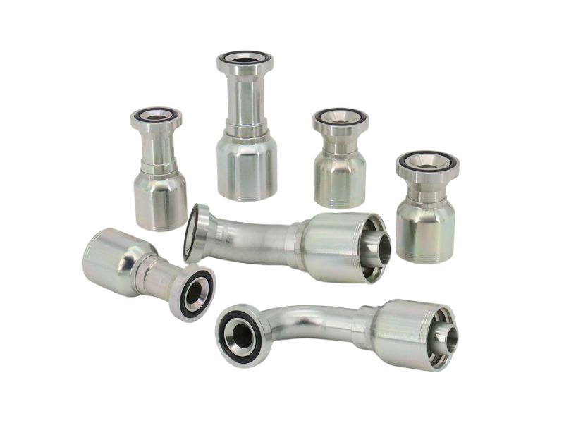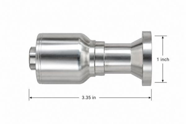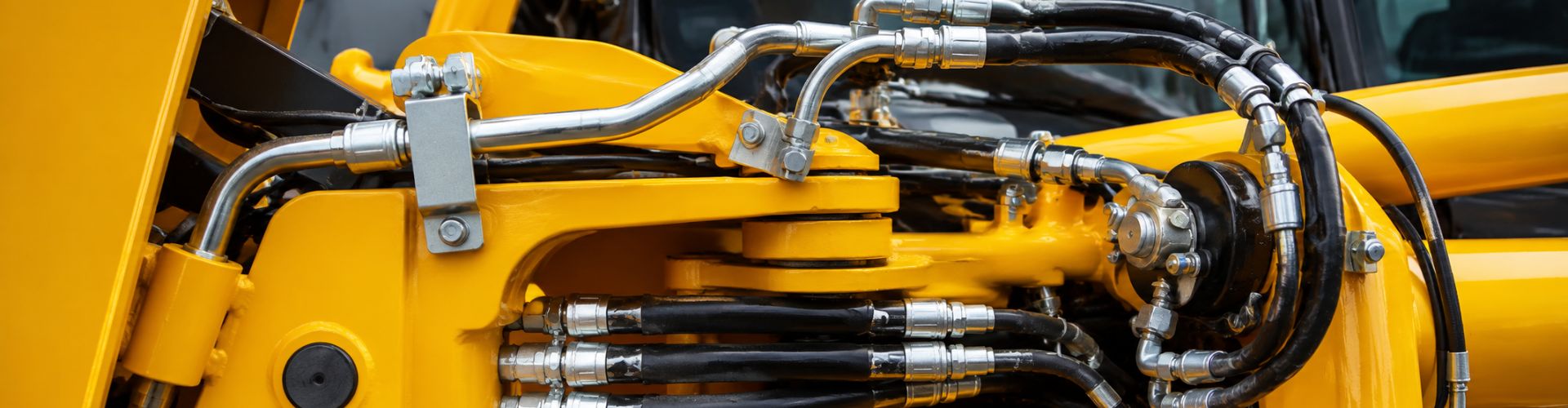
What One Piece Fitting Dimensions Must Be Confirmed

What One Piece Fitting Dimensions Must Be Confirmed?

Confirm the connection, sealing features, hose-side geometry, body dimensions, and installation envelope before identifying or replacing a one-piece fitting. The essential one-piece hydraulic fitting dimensions include thread diameter and pitch, seat or sealing-face geometry, hose stem and ferrule details, overall length, and elbow offsets when applicable. A photo, swivel nut, connection name, or matching dash size can narrow the possibilities, but none proves compatibility. Missing one dimension can lead to a fitting that threads together yet does not seal, a hose-and-fitting combination without valid crimp data, or an assembly that collides with nearby components. The following checks turn an incomplete description into a controlled identification process.

Why Appearance Alone Cannot Confirm a Fitting

Appearance is useful for sorting candidates, but it cannot establish a final fitting model. Similar bodies and swivel nuts may conceal different threads, seats, seals, hose stems, ferrules, or series-specific assembly requirements.

Visible features show only part of the design

A clear photo can reveal whether a fitting is straight, angled, male, female, flanged, or fitted with an O-ring in a visible location. It can also show wrench flats, a swivel nut, an elbow, and obvious damage. However, perspective can distort diameter and length, while dirt, wear, plating, or a retained seal can hide the surface that actually makes the connection.

Terms such as “female swivel” describe movement and connection gender, not a complete standard. They do not establish the thread form, diameter, pitch or TPI, seat angle, sealing face, O-ring arrangement, hose size, fitting series, or elbow orientation. Even a legible old part number should be treated as a lead until it is checked against current technical information and the actual component.
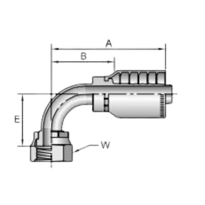
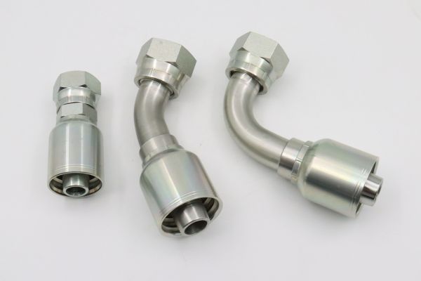
1J978 crimp hydraulic hose fittings drawing Topa

Dash size is not a universal identity

A dash marking may refer to a nominal hose size or another catalog convention, depending on where it appears. It does not prove that the connection end and hose end use the same nominal size, nor does it confirm interchangeability between product series. Two fittings can share a dash designation while using different stem profiles, ferrules, thread connections, or crimp specifications.

The one-piece structure also does not remove the need for verification. In this type of fitting, the body or stem and ferrule are preassembled, attached, or retained together, but exact construction varies by series. Preassembly may reduce separate ferrule picking, yet it does not automatically confirm hose compatibility, correct crimping, pressure suitability, or sealing performance.

Connection-Side One-Piece Hydraulic Fitting Dimensions

Measure the connection end as a complete interface rather than recording only the apparent thread diameter. Reliable hydraulic fitting identification separates thread form, connection standard, diameter, pitch, taper, gender, seat, and seal.

Thread diameter, pitch, and taper

Measure a male thread across its outside diameter and a female thread at the accessible inside diameter using suitable tools and a consistent method. Then determine pitch with a thread-pitch gauge or TPI gauge, as appropriate. A diameter reading alone can leave several possible standards, especially when wear, coating, limited access, or measurement technique affects the result.

Determine whether the thread is straight or tapered instead of judging from a short visible section. Compare measurements along the thread when the applicable identification procedure calls for it, and inspect the thread form rather than forcing the fitting into a known port. Thread engagement is not proof of a match; partial engagement between incompatible forms can damage threads and still fail to create the intended seal.

Connection standard and reference dimensions

The connection standard defines how several features work together. Record only the thread length, nut, shoulder, pilot, flange, or sealing-surface references required by the applicable identification method and verified drawing.

Do not use thread sealant to compensate for a wrong standard, damaged threads, an incorrect seat, or a damaged sealing face. Sealant has a limited role only where the designed connection and current procedure call for it. It cannot convert one thread or sealing system into another.

Seat Angle, Sealing Face, and O-Ring Confirmation

The fitting must seal by the intended surface or seal element, not merely by holding threads together. Confirm the seat geometry, sealing-face condition, and O-ring position independently from the thread measurements.

Identify where sealing occurs

Inspect whether sealing is designed to occur on tapered threads, a flare seat, a cone, a flat face, an O-ring, a bonded seal, or another engineered surface. A female swivel can contain an internal seat that is difficult to see in a straight-on photograph, and different seat forms may sit behind similar nuts. Use an appropriate seat gauge, profile comparison, technical drawing, or verified mating-component data instead of estimating an angle by eye.

Record the seat diameter or other drawing reference dimensions when they are required to distinguish candidates, but do not publish or assume a nominal value without a verified source. Check the face for scoring, deformation, corrosion, embedded debris, or previous over-tightening. A correct standard with a damaged sealing surface may still leak, so identification and condition assessment are separate decisions.
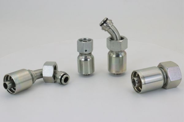
Standard crimp Fitting

Locate and assess the seal

For an O-ring connection, record whether the seal sits on the male end, in a face groove, around a boss, behind a flange, or elsewhere in the designed interface. Note groove condition and the presence of a backup element when relevant, but do not select a replacement seal from appearance alone. Material, dimensions, fluid, temperature, and the applicable component data all affect seal suitability.

A missing O-ring can make a fitting appear to use a metal-to-metal seal, while a loose O-ring may have been added incorrectly. Preserve removed components for examination, but verify the intended arrangement against current documentation. Never pressurize an uncertain connection simply to see where it leaks, and never check a suspected high-pressure leak with a hand.

Hose-Side Stem, Ferrule, and Fitting-Series Checks

The connection end can be correct while the hose end is wrong. A safe replacement requires a documented combination of hose manufacturer or compatible specification, hose series, hose ID, reinforcement, fitting series, ferrule design, and current crimp data.

Measure without treating the stem as universal

Record the hose size indicated by reliable markings and confirm the actual hose ID and construction from current product information. For an unassembled or approved inspection sample, relevant stem features may include insertion length, nipple profile, sealing or retention features, and the position of a hose stop. Ferrule references may include length, outside geometry, retention method, and its relationship to the stem, but measurement must not become an improvised crimp specification.

Do not disassemble a retained one-piece fitting merely to obtain hidden dimensions unless the applicable procedure allows it and the part is being removed from service. Cutting or separating the ferrule can destroy evidence and create sharp or spring-loaded material. When internal geometry cannot be measured safely, use the series marking, verified drawing, or manufacturer data to complete the identification.

Confirm the complete assembly system

The same hose dash size does not guarantee that two stems or ferrules are compatible. Hose cover thickness, reinforcement construction, tube dimensions, fitting-tail design, ferrule compression, and series tolerances can differ. A fitting that slides into a hose is not thereby approved for crimping.

Before assembly, require current data for:

  • the exact hose manufacturer or accepted specification, hose series, construction, ID, and dash size;
  • the fitting body or stem, ferrule, and complete fitting-series identification;
  • hose preparation, including skive or no-skive requirements when applicable;
  • the crimping machine, die set, crimp diameter, insertion method, and inspection criteria; and
  • cleaning, proof or pressure testing when required by the applicable procedure.

Never create a crimp value from an old assembly’s approximate outside measurement. The old part may be worn, incorrectly assembled, or made to different data, and an external reading does not reveal internal compression. Follow the current hose, fitting, and crimp-equipment instructions for the exact combination.

Overall Length, Elbow Geometry, and Installation Clearance

Overall geometry determines whether an identified fitting can actually be installed and routed. Measure from defined reference points and record the fitting orientation, because loose end-to-end measurements can change with swivel position or an unclear datum.
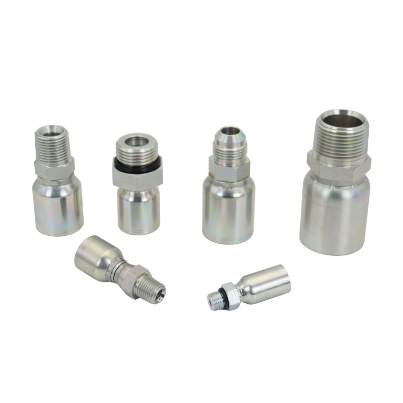
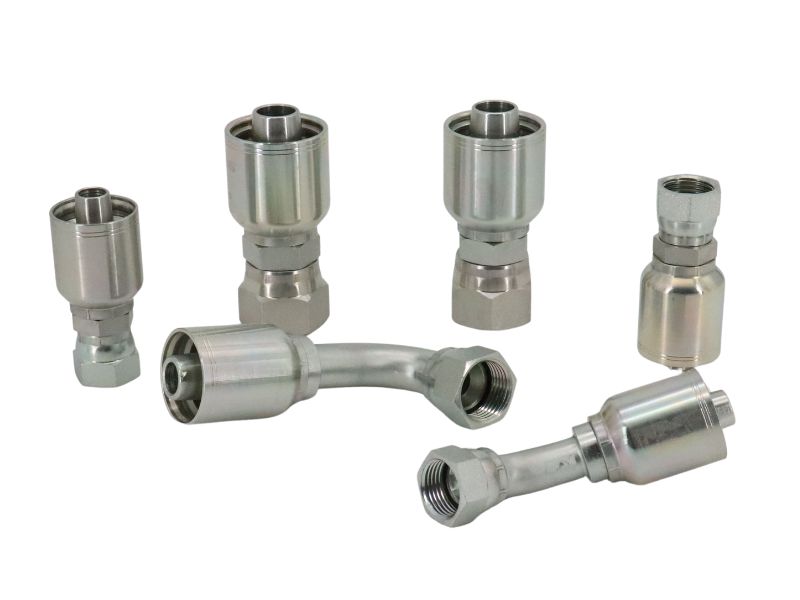
Crimp Hydraulic Fitting Topa

Use consistent body and elbow references

For a straight fitting, record overall length and the location of shoulders, wrench flats, stops, or other drawing references needed for comparison. For a 45-degree or 90-degree fitting, record the relevant centerline offsets, drop length, and connection orientation using the same datums as the technical drawing. Do not compare one supplier’s overall dimension with another drawing’s centerline dimension as though they were equivalent.

Swivel position can also affect a casual measurement. Seat the nut only as the approved measurement procedure requires, without forcing it, and state whether the measurement is taken to a seat, thread end, face, centerline, or body shoulder. Photos should include a scale only as supporting evidence; calibrated tools and written dimensions are needed for final confirmation.

Check the machine envelope

A geometrically different replacement may fit the hose and port yet collide with a guard, cylinder, frame, or adjacent line. Verify wrench access, assembly installation path, bend allowance after the fitting, clamp positions, and clearance throughout machine movement. Elbow clocking is especially important when both ends have fixed orientations or when a swivel cannot rotate after tightening.

Before removal or measurement, stop the equipment, isolate the hydraulic system, release hydraulic pressure and stored energy, secure raised or suspended loads, and follow applicable lockout procedures. Follow the equipment manufacturer’s instructions and use appropriate personal protective equipment. Never loosen a connection to confirm its type while the circuit may still be pressurized.

Step-by-Step Fitting Measurement Process

Use a repeatable sequence that preserves evidence and separates observation from confirmation. This reduces the chance that an early guess about the connection controls every later measurement.

Measure from system context to component detail

Avoid common measurement and ordering errors

Common mistakes include rounding a measured thread to the nearest familiar size, confusing pitch with TPI, measuring across damaged crests, and describing the connection only as “female swivel.” Other errors include copying the hose dash size to both ends, omitting the sealing face, measuring elbow length from inconsistent points, or assuming a photo confirms scale.

Do not order solely from the old part number, especially when the source, revision, or series is uncertain. Do not force a candidate fitting into a port as a thread test, reuse visibly damaged components, or accept an approximate crimp as validation. When measurements conflict with catalog data, recheck the tools, datums, wear, and candidate standard before choosing a replacement.

Information Checklist to Prepare Next

A complete identification package should let another qualified person repeat the comparison without relying on your original guess. Keep the old component available when safe, label every measurement, and distinguish observed facts from unverified assumptions.

Connection and geometry record

Prepare the following neutral information:

Hose and assembly record

Add the hose manufacturer or accepted specification, hose series, construction, ID, dash size, reinforcement, and readable markings. Record the fitting and ferrule series, crimping machine, die set, current crimp specification, preparation method, inspection requirements, and the intended application. Unknown fields should remain marked as unknown until verified rather than being filled with a likely value.

Conclusion

The complete assembly is limited by its lowest-rated component and must follow current manufacturer procedures. Preparing labeled measurements, clear photos, hose data, application conditions, and assembly information makes the next one-piece hydraulic fitting dimensions decision traceable and safer.

Looking for a reliable one-piece hydraulic fitting supplier or a compatible replacement for an existing model? Contact Topa today to submit your one-piece fitting requirements and receive a detailed technical review and quotation.

FAQ

Can a fitting be identified from its thread diameter alone?

No, thread diameter alone cannot confirm the connection. Pitch or TPI, thread form, taper, gender, seat, and sealing method must also match verified technical data.

Does a female swivel nut identify the sealing standard?

No, a female swivel nut describes only part of the connection. Similar nuts can contain different internal seats, threads, sealing faces, or O-ring arrangements.

Can two one-piece fittings with the same dash size be interchanged?

No, matching dash sizes do not prove interchangeability. Confirm the hose construction, fitting and ferrule series, connection, geometry, and current crimp specification for each product.

Should the old crimp diameter be copied for a replacement fitting?

No, an old external measurement is not a valid replacement crimp specification. Use current data for the exact hose, fitting, ferrule, crimper, and die combination.

What should be done when measurements do not match a catalog drawing?

Recheck the measurement points, tools, thread condition, datums, and assumed connection standard before ordering. If the conflict remains, obtain verified technical confirmation rather than selecting the closest-looking fitting.
Why Do Mixed Hydraulic Connections Need Broader Coverage

Why Do Mixed Hydraulic Connections Need Broader Coverage?

A local market can look simple from a distance: the same repair shops, equipment fleets, factories, and mobile machines appear every month. At the counter, however, their hose ends may follow four different connection systems. One request needs a JIC female swivel, the next needs ORFS, a third arrives with BSP threads, and a large-bore line uses a four-bolt flange. If an alternative fitting range covers only the most familiar family, the sales team may quote individual items but still fail to complete the customer’s hose assembly, repair kit, or maintenance order.

One Local Market Can Contain Four Connection Systems

Equipment origin and age create mixed demand

Hydraulic equipment does not enter a market from one factory or in one year. American-designed mobile equipment may use JIC or ORFS connections. Machinery influenced by British or European practice may contain BSP connections. Pumps, cylinders, and high-flow lines may use SAE four-bolt flanges, especially at larger sizes. Older machines can remain in service beside newer models, and previous repairs may add adapters or locally available hose ends. The result is not one local standard but a layered installed base shaped by equipment origin, age, application, and maintenance history.

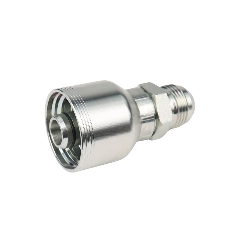
4 wire male JIC crimp fitting

This mix appears inside individual accounts as well as across the market. A maintenance team may operate loaders with JIC ends, agricultural equipment with BSP ports, newer machines with ORFS connections, and power units with flange ports. Seeing only the most frequent family can underestimate the range required for the actual maintenance workload.

Similar appearance does not create compatibility

These connection names are not cosmetic labels. JIC uses straight UN/UNF threads and a 37-degree metal-to-metal flare seal. ORFS also uses straight threads, but sealing occurs at a flat face with an O-ring. BSP must be divided further: BSPP has parallel threads and may seal through a cone, bonded washer, or another defined sealing arrangement, while BSPT has tapered threads and normally relies on controlled thread interference with an appropriate sealing method. A four-bolt flange uses a face seal, O-ring, clamps, and bolts; Code 61 and Code 62 have different dimensions and ratings and must be identified separately.

A thread that starts by hand is not proof of a correct match. The sealing surface, thread form, pitch, diameter, gender, size, and applicable standard all matter. A practical hydraulic fitting identification process checks the seal first, then angle, diameter, and pitch. Broader coverage therefore requires more than adding visually similar ends—it requires distinct, correctly identified product families.

Partial Coverage Can Lose a Complete Order

The missing end controls the value of the basket

Many fitting requests are attached to a larger job. The customer may need hose, two end fittings, adapters, clamps, protective sleeve, and crimping as one usable assembly. If the range includes a common JIC end but not the required ORFS elbow or BSP swivel at the opposite end, the available items do not solve the shutdown. The missing low-value component can determine whether the entire basket is purchased locally or moved to another source.

This is why item-by-item availability can give a misleading picture of performance. A shelf may contain hundreds of fittings and still leave frequent order combinations incomplete. The more useful commercial question is: what percentage of common local assemblies and repair orders can be finished from the planned range? Complete-order coverage connects inventory decisions to the customer’s real outcome—putting equipment back into service.

Adapters are a controlled option, not a universal answer

An inter-series adapter can be the correct engineered solution when its two ends, pressure rating, material, seal, and installation envelope are verified. But using adapters automatically to compensate for every assortment gap creates new problems. Each extra joint adds length, another seal point, more components to identify, and more opportunities for assembly error. On a compact machine, the additional stack height can interfere with guards, frames, or nearby lines. On a hose assembly, it can also change routing and increase leverage at the port.

Use adapters when the design permits them and the complete connection is confirmed. They do not make direct JIC, ORFS, BSP, or flange ends unnecessary. A balanced range combines high-frequency direct ends with validated transition adapters.

Broader Coverage Is a Matrix, Not a Longer Catalog

Map the dimensions that decide order completion

The real assortment is a matrix. Connection family is only its first dimension. A technically useful plan also accounts for hose size and family, end size, male or female form, straight or elbow geometry, sealing method, material, and application risk. Flanges add Code 61 or Code 62, flange size, head style, O-ring, clamp, and hardware requirements. BSP adds the need to distinguish parallel from tapered threads and to document the intended seal.

check before order

A simple coverage matrix can begin with these fields:

This structure exposes practical gaps. For example, the business may carry ORFS straights in common sizes but repeatedly lose orders because 90-degree swivels are missing. It may carry Code 61 flange heads but lack matching clamps or O-rings. It may list BSP products without separating BSPP and BSPT in item descriptions. The matrix turns “we need more products” into specific decisions that can be sourced, labeled, stocked, and measured.

Coverage should follow recurring combinations

Do not start by copying every page of a manufacturer’s catalog. Start with evidence from quotation history, counter requests, returned samples, emergency jobs, machine populations, and lost-order notes. Group requests by connection family and then by the combinations that complete an assembly. This reveals whether the business needs depth in common sizes, selected elbows, mixed-end assemblies, flange kits, or a faster special-order route.

Photographs can support the process, but they do not prove an exact match. Ask for the full fitting, readable markings, thread and seal close-ups, caliper measurements, pitch-gauge results, hose layline, overall length, and machine application.

Build a Three-Level Alternative Range

Stock core, secondary, and special-order items differently

Complete coverage does not mean equal stock for every configuration. A three-level model keeps working capital aligned with demand:

The boundary between levels should be local, not universal. One market may justify deep JIC and ORFS stock; another may need more BSP and Code 61 coverage. Review actual demand, gross margin, replenishment reliability, minimum order quantities, and the value of the full baskets affected. A slow-moving fitting can still merit stock if it repeatedly unlocks valuable hose assembly orders, but that decision should be visible in the data.

Add technical evidence before adding shelf quantity

An alternative item should enter the range only after its identity and application limits are clear. A branded part number or visual resemblance can help locate a candidate, but neither proves interchangeability. Confirm the connection standard, sealing surface, thread, size, dimensions, pressure rating, material, seal compound, and hose compatibility. For crimped ends, use current crimp data for the exact hose-and-fitting system and the available machine and tooling. Trial assemblies and inspection should precede volume commitments.

One-piece construction can reduce the risk of pairing a loose ferrule with the wrong insert, but it does not remove the need to verify the hose, fitting, crimp diameter, insertion depth, and finished assembly.

Operational Control Makes Broad Coverage Usable

Identification and storage must prevent near-match errors

As coverage expands, the risk of picking a near match also expands. JIC, ORFS, BSPP, BSPT, and flange components should have unambiguous item codes and descriptions. Labels should show the connection family, size, hose size, geometry, and material. Separate bins and visual markers help prevent similar-looking items from being mixed. Thread gauges, calipers, angle gauges, and seal inspection tools should be available where parts are received and identified.

The receiving and counter workflow should include a stop rule: if the sealing method or standard is uncertain, the item is not released as an exact alternative. This avoids turning speed into returns, leaks, rework, or damage to the customer’s port. The same rule applies to flange hardware. Code, size, clamps, bolts, and O-ring must be treated as a system, not as interchangeable loose pieces.

The quotation process should show complete solutions

A broad range creates value only when the sales team can find and explain it. Search tools and quote templates should allow filtering by connection family, seal, size, geometry, and compatible hose. Mixed-end assemblies should be easy to specify without relying on memory. If a direct end is unavailable, the quote should distinguish a validated adapter solution from a special-order direct end and explain the effect on dimensions and lead time.

For uncertain samples, use a one-page confirmation record. It should capture photos, measurements, hose data, application, pressure and temperature information, fluid, quantity, required date, and the customer’s approval of the identified configuration. This creates a reusable technical record for repeat orders and reduces the chance that the same fitting is re-identified from scratch.

Wider Coverage Strengthens the Commercial Offer

It supports a second price band without weakening trust

When only the original branded fitting is available, every price discussion becomes a choice between discounting that item and losing the request. A verified alternative range creates a second price band while preserving a clear premium option. The customer can compare lead time, technical confirmation, warranty terms, and price without being told that two parts are identical merely because they connect to the same nominal size.

Mixed-standard coverage makes this approach more credible. Offering an alternative only for JIC suggests a fragmented program; supporting the recurring JIC, ORFS, BSP, and flange combinations shows that the range was built around complete local maintenance needs. That consistency helps the sales team protect margin on branded parts while winning budget-sensitive work with a technically controlled option.

JIC crimp on Hydraulic fitting Topa

Service capability becomes harder to replace

Price can be copied quickly. A reliable map of the local installed base, trained identification, suitable stock, current crimp data, and complete-order support takes longer to build. Customers remember the source that can inspect an unfamiliar end, separate BSPP from BSPT, identify the correct flange code, and finish a mixed-end hose assembly without repeated trial and error.

Every confirmed sample and completed order improves demand intelligence. Over time, the business learns which combinations deserve stock, which can remain special order, and where one missing component blocks a larger basket.

Measure Coverage by Outcomes, Not SKU Count

Use metrics tied to completed work

A larger SKU count is not automatically better. Track whether the range solves more of the work that arrives. Useful measures include:

Review these measures together. A high fill rate bought with excessive aged stock is not healthy. Strong inventory turns accompanied by frequent incomplete orders may mean the range is too narrow. The target is not maximum stock or minimum stock; it is the best repeatable balance between order completion, response time, technical control, and working capital.

Expand in controlled waves

Begin with a sample of recent requests and identify the smallest set of additions that would have completed the most valuable recurring orders. Validate technical documents and sample assemblies, then place a limited initial quantity. After a defined review period, compare actual sales, attached hose revenue, lost requests, returns, and stock movement. Promote proven items to core stock, retain justified secondary items, and remove assumptions that demand does not support.

This phased method is safer than a large catalog purchase. It makes every expansion decision traceable to a local need and allows the team to correct descriptions, binning, training, or sourcing before scaling. Broader coverage becomes an operating capability rather than a one-time inventory event.

Conclusion

Mixed JIC, ORFS, BSP, and flange demand is not a reason to buy everything. It is a reason to understand the local installed base more completely. When the alternative range is built around complete assemblies, verified technical boundaries, and measured order outcomes, broader coverage reduces lost baskets without turning the warehouse into an uncontrolled catalog.

Frequently Asked Questions

Does broader coverage mean stocking every JIC, ORFS, BSP, and flange fitting?

No. It means stocking the combinations that repeatedly complete local orders, keeping selected secondary items for meaningful gaps, and providing a controlled special-order route for rare configurations. The coverage matrix should be based on demand and complete-order value.

Can an adapter solve every missing connection?

No. An adapter must be technically compatible and acceptable for the application’s pressure, material, seal, space, and routing requirements. It also adds length and another joint. Direct ends should cover common assemblies where adapters would create avoidable complexity.

Why must BSPP and BSPT be tracked separately?

They use different thread forms and sealing approaches. BSPP is parallel; BSPT is tapered. Treating “BSP” as one item description increases identification and sealing errors. The actual port, mating end, and seal arrangement must be confirmed.

Are Code 61 and Code 62 flanges interchangeable at the same nominal size?

No. They have different dimensional and pressure characteristics. Confirm the code, size, flange head, port pattern, clamps, bolts, O-ring, and application requirements before selection. Parker’s flange documentation likewise separates connections governed by SAE J518 and ISO 6162.

What is the first step in expanding an alternative fitting range?

Analyze recent quotations, completed assemblies, emergency requests, lost orders, and returned samples. Build a matrix by connection family, size, geometry, hose compatibility, and order value. Then validate a small first wave before increasing stock.

How to Add a Second Price Band Without Cutting Brand Margin

How to Add a Second Price Band Without Cutting Brand Margin

When end customers keep pushing for lower prices, repeatedly discounting branded hydraulic fittings is usually the wrong response. It trains the market to wait for concessions, weakens the reference price, and uses one product line to serve applications with very different risk and willingness to pay. A better approach is to keep the branded-original offer intact and add a separately governed validated-alternative price band. The second band should have its own SKU identity, technical approval, quotation wording, price floor, and application boundaries so it captures price-sensitive demand without pretending to be the branded product or forcing brand margin downward.

Discounting One Line Does Not Create Segmentation

Repeated concessions damage the reference price

When the same branded item is quoted at progressively lower prices, the buyer learns that the first price was negotiable rather than tied to value. Sales then has to defend yesterday’s higher transaction, and future requests begin from the latest concession. Lower gross profit may not be recovered by extra volume because every discounted unit gives up margin immediately while incremental demand remains uncertain. The commercial problem is not simply an expensive fitting; it is a portfolio with only one answer for buyers who value different combinations of brand, traceability, availability, and price.

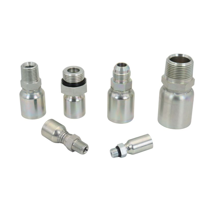
Male Hydraulic Crimp Fitting

A second band creates a real choice

Tiered pricing works when each offer has distinct value and conditions, not when the same item receives two unexplained prices. The good-better-best pricing concept describes how differentiated options can serve different willingness to pay without relying only on discounts; hydraulic fittings often need two controlled bands rather than three marketing packages. The branded-original band protects applications that require specified provenance and lower substitution risk. The validated-alternative band creates a lower entry price by changing the product and service proposition transparently, not by hiding a discount.

Define Two Bands by Application, Not by Adjectives

The branded-original band has a clear job

Keep the branded band for orders where the drawing, equipment manual, contract, warranty, internal standard, or end user specifies the original brand. It also remains the default for safety-critical systems, unclear applications, exceptional pressure or temperature conditions, specialized fluids, high downtime cost, or any request that lacks enough information to validate a replacement. Its value includes documented configuration, known system fit, established traceability, and reduced approval work. Do not describe this band only as “premium,” because the practical reason to select it is controlled risk, not prestige.

The validated-alternative band needs a narrower gate

Use the second band where the complete end connection, hose series and size, material, finish, pressure and temperature conditions, fluid, shape, envelope, and crimp data can be verified. Suitable starting points are repeat configurations with clear drawings, stable demand, measurable quality requirements, and applications whose substitution process is understood. High-risk, ambiguous, or brand-mandated work should not be forced into the alternative band merely to meet a target price. The one-piece fitting ordering checklist provides the technical fields needed to decide whether a candidate can enter the controlled alternative line.

Build the Alternative Line Before Setting Its Price

Select SKUs from evidence, not catalog breadth

Start with a small, data-supported group rather than copying an entire branded catalog. Review lost quotes, discount requests, sales frequency, equipment population, repair consequence, connection standards, hose systems, and availability problems to find items where price pressure is real and technical validation is practical. Exclude items whose only evidence is a single unusual order or whose application cannot be reconstructed. The goal is not the largest cross-reference list; it is a repeatable set of alternatives that sales and assembly personnel can identify correctly.

Validate the complete hose-end system

A branded part number is a cross-reference starting point, not proof that another product is completely interchangeable. Confirm thread, seat, seal, hose ID, hose construction, fitting series, material, finish, shape, pressure and temperature suitability, dimensional envelope, and valid crimp data. Inspect samples and controlled assemblies before routine release, then record deviations and approval limits. The one-piece fitting trial-order method keeps evaluation focused on compatibility, assembly accuracy, consistency, documentation, and repeat supply rather than purchase price alone.

Use an entry checklist for every alternative SKU:

Create independent internal item codes, descriptions, labels, bins, photos, and approved-vendor records. Do not place the alternative under the branded part number with a hidden note, because picking, invoicing, and future replenishment will eventually lose that context; the fast-moving one-piece fitting stock framework likewise depends on identification, validation, and stock control rather than catalog breadth alone. Quote wording should say “original branded item” or “validated aftermarket alternative referenced to [part number]” and should never use “genuine,” “OEM,” or “fully interchangeable” without evidence and authorization. Clear identity protects trust, makes price comparison legitimate, and lets later margin analysis distinguish a strategic second band from an unrecorded substitution.

clear label

The selected band must remain visible from quotation through purchasing, assembly, inspection, invoice, and shipment. Require renewed approval when a source, drawing, material, finish, hose combination, or crimp specification changes, and prevent purchasing personnel from replacing one approved alternative with another low-cost source under the same item code. Receiving inspection should check the exact alternative code rather than only the reference brand number, while stock locations, barcode rules, and pick documents should minimize mixed selection. A low-cost line that cannot be controlled operationally will create returns, rework, leakage complaints, mislabeling, and brand damage that overwhelm its apparent unit margin.

Price Each Band From Its Own Economics

Protect floors instead of improvising discounts

Set separate price floors using the full economics of each band. The branded floor should account for acquisition cost, availability, service, inventory exposure, payment terms, and the value of preserving a specified original option. The alternative floor must include validation, samples, inspection, freight, financing time, lower-volume risk, documentation, returns, and technical support rather than applying a simple percentage below brand.

Create a meaningful but defensible gap

The price difference should be large enough to give a price-sensitive buyer a real choice, yet it must come from different product economics and value—not an arbitrary target. Do not publish a universal gap because freight, duties, order size, validation cost, supply stability, and local competition vary by SKU and transaction. If the two bands land too close, the alternative adds complexity without changing the decision; if the gap is achieved only by ignoring inspection and after-sales risk, it is not sustainable. Review the gap using net contribution after all transaction costs, not list-price percentage alone.

Quote the Choice Without Cannibalizing the Brand

Lead with application fit before price

Ask whether the original brand is mandatory, whether the equipment is under warranty, how costly failure or downtime would be, and whether complete technical data is available. Recommend one default based on those answers, then show the second option only when its gate is satisfied. This prevents the lower band from becoming the automatic first line on every quote. The conversation changes from “How much discount can you give?” to “Which risk-and-value package fits this application?”

Use concise option language:

Never make the cheaper choice deceptive

Show both identities, technical scope, included services, delivery conditions, and approval requirements. Do not preselect the alternative, remove the branded label from the comparison, or imply that the buyer requested an original and received “the same thing.” If the alternative needs a trial, sample, or written acceptance, state that before the order rather than in a later disclaimer. Transparent choice protects the branded line because customers can still see what its higher price buys.

Measure Portfolio Profit, Not Only Conversion

Track whether the second band adds demand

The key question is whether the alternative wins price-sensitive business that the branded line would otherwise lose, not whether it produces more low-price transactions. Track quote conversion by band, gross-margin dollars, realized price versus floor, returns, rework, technical support time, inventory turns, stockouts, and repeat purchases, then compare those results with the same customers’ earlier branded buying patterns. Also review which applications chose each band and why, how often a lower quote needed exceptional approval, and whether alternative sales led to complete hose assemblies or only isolated low-value items. This reveals whether the alternative is expanding coverage, creating useful attachment sales, or merely replacing profitable branded demand while adding operational cost.

Set explicit cannibalization controls

Audit cases where an existing branded buyer moves to the alternative, especially when the application still values the original benefits. Require reason codes for price pressure, brand mandate, validation status, and selected band, then review exceptions rather than rewarding volume alone. Sales incentives should recognize contribution margin and compliant product selection, not only revenue. Expand the alternative line only after results show acceptable technical performance, inventory movement, and incremental contribution.

Conclusion

Persistent price pressure should lead to better segmentation, not endless discounting of branded hydraulic fittings. Keep the branded-original band for specified, critical, unclear, and high-consequence applications, and build a separate validated-alternative band for complete, repeatable, approved specifications. Separate the two through item codes, labels, stock, quotation wording, price floors, technical records, and change control, while training sales and warehouse personnel to preserve the selected identity through every transaction. Price each from its own total economics, present the lower band only when its application gate is met, and measure incremental margin alongside returns, support time, inventory movement, and cannibalization; the second price band succeeds sustainably when it wins business the brand line could not, not when it quietly replaces profitable branded orders or hides the true cost of technical risk.

FAQ

Should every branded fitting receive an alternative SKU?
No; prioritize repeat, technically clear, price-sensitive configurations and exclude applications where validation cost or risk outweighs the opportunity.

Can the alternative use the branded part number on its label?
Use the brand number only as a cross-reference field and give the alternative its own clear manufacturer and internal item identity.

How should sales respond when only the lowest price matters?
Offer the validated band if the application qualifies; otherwise state which missing or high-risk condition prevents responsible substitution.

Will a lower band always reduce average margin?
Not necessarily, but judge it using incremental contribution, transaction costs, returns, and cannibalization rather than unit margin or conversion alone.

When should the alternative line be expanded?
Expand after verified demand, stable technical results, acceptable returns, reliable supply, healthy inventory movement, and evidence that the line adds rather than shifts profit.

Why One Special Parker 43 End Can Lose the Whole Order

Why One Special Parker 43 End Can Lose the Whole Order

When a hose assembly needs one special Parker 43 end, the missing item is not merely one fitting—it is the component that can block the entire assembly order. The standard hose and common end have little commercial value if the finished assembly cannot connect to the equipment. A special Parker 43 fitting therefore affects conversion because it controls whether the complete, installable result can be supplied with credible technical and delivery commitments.

A Hose Assembly Is One Dependent Product

Both ends define whether the assembly has value

A finished hydraulic hose assembly combines the hose, two end connections, crimps, overall length, orientation, cleanliness, identification, and application requirements. These elements are not separate line items once the assembly must fit a machine. If one end cannot mate with the port, the correct hose and common fitting cannot complete the repair. The order is evaluated by the assembly’s ability to install and operate, not by the percentage of components that were easy to source.

1FU43 crimp hydraulic fittings Topa

The uncommon end often carries the equipment interface

The special end may be the only component that matches a legacy port, metric or Japanese connection, block-style elbow, banjo, unusual flange, reducer, flat seat, or restricted installation envelope. “Special” may simply mean low local demand, a discontinued machine platform, unusual material, or incomplete identification, but its function remains essential and its replacement evidence must still be complete. Without that exact interface, the assembly has no correct second endpoint, and offering a common-looking alternative only transfers the identification problem to installation.

The Special End Freezes the Assembly Specification

Cut length depends on both fitting dimensions

Overall assembly length is not the same as raw hose cut length. Cut length as the required overall assembly length minus the dimensional deductions associated with both ends, commonly shown as B1 and B2, so the calculation belongs to the approved pair of fittings rather than to the hose alone. If the special end changes, its stem, insertion, or cutoff dimension can change the hose cut length even when the requested overall length stays fixed; an elbow may also change the datum used for measuring overall length. Cutting hose before the candidate end is frozen can produce a finished assembly that is too long or too short, creating rework and wasting otherwise usable components. On a multi-assembly order, repeating the same unverified deduction can turn one unresolved end into a batch-wide dimensional error.

Orientation and clearance also depend on the final part

An elbow, banjo, block end, or offset connection establishes where the hose leaves the port and how the second end must be clocked. A substitute with the same thread and seat may still have another drop, body width, nut envelope, or hose-centerline position. That difference can move the hose into a guard, cylinder, hot surface, or bend tighter than the specified minimum radius. The earlier one-piece fitting identification checklist is therefore more valuable when it includes the complete assembly and installation space, not only a close-up of the loose special end.

Technical Uncertainty Quickly Becomes Commercial Risk

A partial quote does not solve the buyer’s problem

Quoting the hose, common end, and labor while marking the special end “to be confirmed” may create a fast price, but it does not create a reliable complete-assembly offer. The buyer still has to find the missing interface, coordinate another source, accept a split shipment, or assume responsibility for a substitute that has not been validated, while the quoted common items may sit unused. This weakens the comparison against any quote that provides a finished, traceable assembly with one accountable specification and delivery date. The apparent fitting shortage becomes a lost order because the competing decision is between complete uptime support and an unfinished collection of parts, not between the unit prices of two fittings.

1UT43 one piece fitting Topa

Unqualified delivery promises damage trust

A lead time based only on common components is not the assembly lead time. The special end may require drawing confirmation, current stock verification, a sample, alternate material review, incoming inspection, and trial assembly before the hose can be cut and crimped. Promising the common-item date and revising it later makes the technical gap look like poor order control. A stronger response states the confirmed portion, the exact blocking field, the owner of the next action, and the date on which a complete commitment can be issued.

A Cross-Reference Must Be Validated at Assembly Level

Similar port descriptions are only a starting point

A Parker number, photograph, or generic description can identify candidates, but it does not prove complete interchangeability. Confirm the full suffix, connection standard, thread diameter and pitch, seat or sealing method, hose size, fitting series, shape, material, finish, and dimensional envelope. Then compare the candidate with the actual mating port and installation. The one-piece fitting cross-reference process should organize evidence and exclusions rather than turn brand-code similarity into an automatic replacement claim.

Hose and crimp compatibility must remain controlled

Parker 43 Series fittings are permanent crimp-style components used with specified hose families and assembly data; the one-piece construction reduces separate ferrule-selection errors but does not make every hose of the same ID compatible. The exact hose series, size, crimper, dies, insertion depth, preparation method, and final crimp requirement must be established from current instructions.

Recover the Order by Solving the Bottleneck First

Triage the special end before pricing everything else

At inquiry intake, identify which line or assembly contains the least common end and move it to the first technical review. Common hose and fitting availability can be checked in parallel, but the commercial offer should not be finalized until the bottleneck has a defined resolution path. This reverses a common workflow in which the easy majority is quoted first and the decisive minority is discovered later. Early triage protects the time spent pricing, freight planning, and delivery coordination for the rest of the order.

Use four possible resolution paths:

Present options as complete assembly outcomes

Do not present a cheaper fitting as an equivalent option unless it has passed the same technical checks. Compare alternatives by finished assembly: exact port match, approved hose and crimp combination, overall length, orientation, pressure and fluid suitability, validation work, delivery date, and total installed risk, including whether the alternative changes clamps, guards, adapters, or service access. An adapter-based option may be available sooner but add connections and alter routing; an exact end may take longer but preserve the original envelope; a verified replacement may balance both only after dimensions and assembly data are approved. The buyer can make a rational decision only when each option shows a complete installable result, its open assumptions, and the event that converts its provisional date into a committed date.

Build a Confirmation Package for the Entire Order

Collect assembly data in one record

The confirmation package should connect every assembly line to its two ends, hose, length, orientation, application, and inspection criteria. For the special end, attach the original number source, photos, measurements, catalog or drawing revision, candidate comparison, and approval status. Use a consistent internal item code so the approved end cannot be replaced by a visually similar part during picking.

Request or verify these fields:

Release purchasing and production from the same revision

The approved revision must control quotation, purchasing, assembly, inspection, labeling, and shipment, with the same end descriptions and drawing references visible to every function. If the special end changes, recalculate cut length, review orientation and clearance, verify crimp data, update price and delivery where affected, and obtain approval again before production; do not let a purchasing substitution bypass the assembly review. Do not reuse a permanent fitting removed from a used hose as a way to rescue the order.

Conclusion

One special Parker 43 end can determine the whole hose assembly order because every useful outcome depends on a complete, compatible, installable assembly. That end can control the port interface, hose cut length, crimp process, orientation, routing, inspection, and credible delivery date. Treat it as the first technical bottleneck rather than the last missing SKU. Confirm the full number and geometry, validate the hose-and-crimp combination, compare alternatives as finished assemblies, and release every department from one approved revision that preserves the dimensions, assumptions, and approval evidence needed for repeat work. When the special endpoint is solved early, the rest of the order becomes executable; when it remains vague, even fully stocked common components cannot create a finished result.

FAQ

Can the assembly be quoted while the special end is still unconfirmed?
Provide a clearly conditional budgetary quote if useful, but do not present the assembly price or delivery as final until the blocking technical fields are resolved.

Can a standard fitting plus an adapter replace the special end?
Only after the added joints, pressure rating, sealing systems, routing, clearance, and equipment approval are verified for the complete assembly.

Why not cut the hose while waiting for the fitting?
The final end can change the dimensional deduction and therefore the cut length needed to achieve the specified overall assembly length.

Can the old permanent fitting be cut off and reused?
No; a permanent crimp fitting removed from a used hose should not be reused to build the replacement assembly.

What should be stocked after the order is completed?
Use verified demand, equipment population, repair consequence, lead time, and repeat frequency to decide whether the special end deserves stock rather than treating one order as universal demand.

How One Card Confirms an Urgent Parker Fitting Order

How One Card Confirms an Urgent Parker Fitting Order

When someone requests one urgent Parker fitting, the fastest safe response is not an immediate cross-reference—it is a one-page verification card that turns a short message into an approved specification. The card should show what was requested, what the sales team verified, what remains unknown, and exactly what the buyer is confirming. This prevents a familiar failure: everyone moves quickly, but one missing suffix, hose size, seat type, angle, or crimp requirement sends the wrong part.

Urgency Changes the Communication, Not the Criteria

One part can still contain several decisions

A request for one part number looks simple because the quantity is small, yet the technical decision may still include brand series, connection type, port size, hose ID, shape, drop, material, and assembly method. A Parker base number without its full suffix may represent a family rather than one orderable configuration. A photographed label may also contain a character that was read incorrectly, or the number may come from an old invoice rather than the part installed on the machine. The one-page card must therefore preserve the exact source of the number instead of treating every typed code as equally reliable.

check before order

Speed comes from parallel confirmation

The card shortens the process by placing the requested part, catalog interpretation, missing facts, and approval line in one view. Sales can cross-check the current catalog while the customer sends a photo or hose layline, instead of waiting for a long sequence of separate questions. The goal is not to collect every possible hydraulic parameter; it is to collect every field that can change this specific item or make its use unacceptable. A well-designed card helps both sides see the last open question immediately.

Start With the Part Number and Its Evidence

Record the complete code without normalizing it

Copy the part number exactly as supplied, including every prefix, suffix, hyphen, material code, and package or regional marker. Do not silently correct a character that looks unusual, because 0/O, 1/I, 5/S, or a missing dash can redirect the search; place uncertain characters in brackets and ask for a second view. Ask where the number came from: fitting stamp, hose tag, equipment manual, drawing, previous order, invoice, or memory, and record that source on the page so a later reviewer understands the evidence. A number read directly from the installed assembly and supported by the recommended fitting photographs and markings carries different identification value from a number copied from an unrelated purchasing record, especially when equipment has been modified since the record was created.

Translate the code into a plain description

After locating the current catalog entry, write the interpreted specification beside the code: product series, connection standard, gender, seat or seal, port size, hose ID, straight or elbow shape, material, and other listed options. Parker product pages show why this matters; a complete item can distinguish the port connection, hose size, shape, thread, and material rather than presenting only a family label, while a base code can hide several suffix combinations.

Confirm the Connection and Hose as Separate Sides

The port end needs its own evidence

The connection side must state the standard and sealing method, not only male, female, swivel, or flange. Record thread diameter and pitch when identification is uncertain, plus straight or tapered form, seat angle, O-ring or sealing face, and fitting orientation. The earlier female swivel identification process demonstrates why generic descriptions can point to incompatible JIC, SAE, pipe, BSP, metric, DIN, or ORFS connections. Clear photos should show the complete end, threads, and sealing surface with enough scale to support—not replace—measurements.

Standard crimp Fitting

The hose side needs current assembly data

If the item will be crimped to hose, the card must identify the hose manufacturer, series, hose ID or dash size, fitting series, and current crimp-data source. Matching dash size alone does not establish hose construction or fitting compatibility, and a one-piece stem-and-ferrule assembly does not create a universal crimp diameter. For a loose fitting sold as a replacement, state whether the recipient will assemble it and whether the exact hose-and-crimp combination has been verified.

Ask Only Questions That Can Change the Decision

Use a stoplight rule for missing information

Mark each field green, amber, or red. Green means supported by current catalog data or clear physical evidence; amber means plausible but awaiting confirmation; red means the part cannot be released because the missing fact can change the connection, hose assembly, pressure suitability, or safe installation. Assign one owner and one next action to every amber or red line—for example, “customer to send seat photo” or “sales to verify current crimp table”—so the card drives resolution instead of merely displaying uncertainty. Quantity, requested date, and delivery route may affect service, but they do not compensate for a red technical field, and a promised dispatch time should remain conditional until the red field closes. This visual rule keeps the card short while preventing urgency from hiding the only question that matters.

Use red status when any of these remain uncertain:

Remove questions that do not affect this item

Do not mechanically copy a full inquiry checklist into every urgent exchange. A rigid adapter does not require hose and crimp fields; a straight fitting does not need elbow clocking; a confirmed original item may need less dimensional evidence than an aftermarket replacement. Keep irrelevant fields off the visible card or mark them not applicable with a reason. The customer is more likely to confirm a focused page when each question clearly changes the selected part, assembly, or risk.

Use a One-Page Card That Invites a Clear Reply

Copy-ready Parker fitting verification card

The following template is designed for email, PDF, or a messaging screenshot. Keep the checked catalog description and open fields on the same page, attach photos separately, and use revision numbers when the card changes. Do not fill unknown information with assumptions; write Not confirmed and assign the appropriate stoplight status.

URGENT PARKER FITTING VERIFICATION CARD
Card ID / Revision: _ Date: _
Required date: _ Quantity: _

1. REQUEST RECEIVED
Parker number exactly supplied: ________
Number source: ☐ Fitting stamp ☐ Hose tag ☐ Drawing ☐ Manual ☐ Previous order ☐ Other
Existing part or replacement candidate: ________

2. CATALOG DESCRIPTION CHECKED BY SALES
Series: _ Port connection and size: _
Thread / seat / seal: _ Hose ID or second end: _
Shape / angle / drop: _ Material / finish: _
Catalog or drawing reference and revision: ________

3. PHYSICAL AND APPLICATION CONFIRMATION
Photos and markings received: ☐ Yes ☐ No
Hose manufacturer / series / size: ________
Crimp specification source: ________
Equipment / location: ________
Working pressure / temperature / fluid: ________
Installation clearance or orientation limits: ________

4. STATUS
☐ GREEN—Specification supported
☐ AMBER—Awaiting: ____________________________
☐ RED—Do not release because: __________________

5. CONFIRMATION REQUIRED
“I confirm the selected item and description above match the required connection, hose or second end, shape, quantity, and intended application. Any field marked amber or red must be resolved before release.”
Confirmed by: _ Company / team: _ Date: __

Make confirmation binary and traceable

End with one specific action: confirm the card as written or return corrections in the marked fields. Avoid “Please check” because it does not say whether silence, a thumbs-up, or partial feedback authorizes release; the reply should identify the card revision and repeat any accepted exception or limitation. Save the approved revision with the quote, order, photos, and catalog reference, and copy the final description into the internal item record so the commercial document and technical approval do not carry different wording. If a correction arrives after approval, issue a new revision and obtain confirmation again instead of editing the archived page silently.

Prevent the Card From Becoming False Assurance

Confirmation does not transfer engineering responsibility

A signature or message reply documents shared facts; it does not make an unsuitable assembly safe. The sales team should not ask the customer to approve a parameter that neither side has verified, and the card should not convert unknown application conditions into a waiver. Safety-critical, unusual-fluid, extreme-temperature, high-impulse, or unclear installations may require the equipment, hose, fitting, or crimp-system technical authority before release.

Check the received item against the approved page

The verification loop ends only when the physical item agrees with the approved card. Before shipment or assembly, compare the part marking, packaging label, connection, size, shape, material indicator, and quantity with the approved revision; where replacement risk justifies it, add dimensional or sample checks. A one-page card that is never used for outgoing inspection is only a conversation record. When the match is complete, retain the card so the next urgent request can begin from confirmed data instead of another one-line message.

Conclusion

An urgent Parker fitting request should never be confirmed by part number, appearance, or a short description alone. A clear verification card helps both the buyer and supplier confirm the complete part number, connection type, hose size, sealing method, material, application, and crimping requirements before the order is released. This reduces the risk of receiving the wrong fitting, delaying repairs, or creating unsafe hose assemblies.

If you need Parker-compatible hydraulic fittings, send Topa your existing part number, fitting photos, hose information, required quantity, and application details. Our team can help verify the specification, recommend a suitable replacement, and prepare a quotation for standard, trial, or bulk orders. Contact us today to confirm your fitting and place your order with greater confidence.

FAQ

Is a complete Parker part number enough to skip the card?
Not always; record the number source and confirm the current catalog description, quantity, and intended use, especially when the request involves a replacement.

Can the customer confirm by replying “OK” in a message?
Yes, if the reply clearly refers to the final card revision and your process records who confirmed it and when.

Should price and delivery appear on the technical card?
The required date and quantity belong on the card, but commercial terms can remain on the quotation unless they affect the identified item or approval.

What if no hose information is available?
If the fitting will be crimped to hose, keep the card amber or red until the exact hose and valid assembly data are established.

Does the same card work for adapters and flange components?
Use the same decision structure but remove hose and crimp fields that are not applicable and add the dimensions, seals, hardware, or flange code that can change that item.

Why “1-Inch Flange” Is Not A Complete Hydraulic Fitting Quote

Why “1-Inch Flange” Is Not A Complete Hydraulic Fitting Quote

“1-inch flange” is not enough information to recommend a Parker 43 flange replacement because it identifies only a nominal connection size—and sometimes not even which component that size describes. It does not establish whether the port is SAE Code 61 or Code 62, what hose ID is required, whether the fitting is straight or angled, or which hose and crimp specification must be used. The phrase can therefore lead to a fitting that looks close but cannot bolt up, cannot handle the application, or cannot be assembled safely. A reliable recommendation starts by converting the verbal description into a complete, measurable specification.

One Inch Can Describe More Than One Feature

Flange size is not automatically hose size

The first problem is semantic: “one inch” may refer to the nominal flange size, the hose inside diameter, the port bore, or a dimension someone measured on the old part. Those values are related only in some configurations. A flange fitting can use a 1-inch flange head with a smaller hose, and a 1-inch hose can terminate in a flange head of another nominal size when the catalog offers a reducer combination. Unless the requester states what was measured and where, the inch value cannot be placed in the correct field of a part number.

Flange crimp on Hydraulic fitting Topa

Parker part numbers expose the missing distinction

Both 11543-16-12 and 11543-16-16 are straight SAE Code 61 flange-head fittings with a 1-inch flange, but the first is listed for 3/4-inch hose ID and the second for 1-inch hose ID. The base series and flange size therefore do not identify the hose end. A recommendation made from “Parker 43, 1-inch flange” can select the wrong stem and ferrule combination even before pressure, material, orientation, and physical clearance are considered.

The Flange Series Must Be Identified First

Code 61 and Code 62 are different interfaces

SAE Code 61 and Code 62 four-bolt flange connections are separate dimensional systems, commonly associated with ISO 6162-1 and ISO 6162-2. They may look similar in a photograph, but the flange-head outside dimensions, thickness, clamp and bolt pattern are not the same. That difference is enough to prevent correct clamping or O-ring compression, so the pressure series cannot be guessed from nominal size.

“Parker 43” does not resolve the pressure series

The 43 Series name identifies a family of permanent crimp-style hose fittings, not a universal flange pattern. If the existing machine port is Code 62 or another flange system, the answer may require a different fitting family rather than a nominally similar 43 Series part. This is why a cross-reference should begin with the port standard and the complete original part number, not with a brand family name followed by an inch value.

A Flange Replacement Has Several Independent Interfaces

Confirm the flange head and sealing system

A four-bolt hydraulic flange connection normally seals with an O-ring at the flange head against the port face; the bolts and clamp halves retain the head and create the specified compression. Identification should therefore include the head OD, head thickness, bolt-hole spacing at the mating port or clamp, port-face condition, O-ring groove location and dimensions, and the applicable standard. Do not treat the clamp as proof of the head series, because loose hardware can be mixed during maintenance.

Confirm the hose end as a separate system

After identifying the flange interface, verify the hose manufacturer, hose series, construction, ID or dash size, and the fitting series approved for that hose. A one-piece fitting generally retains the stem and ferrule as one assembly, which can reduce errors caused by selecting a separate ferrule from the wrong family. It does not make the fitting compatible with every hose of the same nominal ID, and it does not supply a universal crimp diameter. The valid hose-and-fitting combination, preparation method, insertion depth, dies, crimper settings, and inspection limits must come from current data for the exact components being assembled.

Shape and Installed Geometry Can Still Reject the Part

Straight and elbow styles are not routing equivalents

Even after the flange code and hose size are known, the fitting style remains open. Parker’s 43 Series Code 61 listings include straight and several angled forms, and an old machine may depend on a specific elbow angle and drop to keep the hose away from a frame, cylinder, guard, or hot surface. Replacing an elbow with a straight head and forcing the hose to turn immediately can violate the hose’s minimum bend radius or load the flange connection sideways. Replacing one elbow with another that has a different centerline or body envelope can also create interference, so use the one-piece fitting cross-referencing process to organize rather than shortcut the comparison.

Orientation and envelope require an installed check

The required geometry includes the angle, drop, flange-head-to-hose centerline, overall length, ferrule envelope, hose OD, and straight section before the first bend. It also includes the clocking needed to aim the hose when the head is held by the split clamp. A loose part placed near the port does not reproduce the installed assembly because the finished crimp, hose stiffness, clamp position, and neighboring motion determine the actual occupied space. Clearance should be checked on an exact sample assembly or an accurate fixture through the equipment’s full operating range.

Build a Reliable Identification From the Old Assembly

Collect evidence before selecting a candidate

Stop the equipment, isolate the energy sources, release hydraulic pressure and stored energy, and follow the equipment manufacturer’s maintenance procedure before removing or measuring a hose assembly. Clean the old connection without damaging the flange face or O-ring groove, then record the full part number and any readable markings. Photographs are useful for documenting shape and condition, but they cannot prove the standard or pressure suitability by themselves. A structured one-piece fitting photo and detail checklist prevents the most important views from being omitted.

1 inch crimp flange

Collect these identification fields:

Use dimensions to confirm, not invent, the standard

Compare the measured values with current drawings for the suspected standard and exact fitting suffix. Measurements should confirm a documented candidate; they should not be rounded until they resemble the nearest catalog size. Check several independent features, because a worn head, compressed O-ring, damaged clamp, or inaccurate tape measurement can mislead a single-dimension comparison. If Code 61 versus Code 62 remains uncertain, do not recommend a part from pressure alone—obtain the equipment port specification, original assembly record, or an authoritative drawing.

Approve a Complete Assembly, Not a Catalog Description

Screen the candidate in controlled stages

The candidate should pass a document review, dimensional inspection, hose-and-crimp review, and installed fit check before it becomes an approved replacement. A cross-reference is only a search aid; it does not prove that two products are fully interchangeable. For a low-risk sample, use the exact production hose, fitting, crimper, dies, and current assembly procedure, then record the finished crimp dimensions and inspection results. Never use a mismatched flange or improvised hardware to restore operation while waiting for clarification.

A practical approval record should show:

An orderable recommendation should no longer depend on verbal interpretation. Its supporting record must show which number describes the flange, which describes the hose, how the connection seals, how the fitting is oriented, and which controlled assembly data applies. This approach also protects future replenishment: a later parts-counter employee can retrieve the approved configuration rather than repeating the same measurements during another outage. If any safety-critical parameter remains unknown, the correct result is “identification incomplete,” not the closest-looking 43 Series flange.

A focused clarification request

Ask for the smallest set of information that closes the actual identification gaps. Avoid responding with a long catalog or a list of possible parts, because that shifts the technical decision back to someone who supplied only a vague size. The request should make clear that flange size, flange code, and hose size are different fields and that a photograph supplements rather than replaces measurements.

Request the following:

Conclusion

A 1-inch flange cannot identify a Parker 43 flange replacement because nominal size answers only one part of a multi-interface decision. The recommendation must also establish the flange standard and pressure series, exact head dimensions and seal, complete part-number suffix, hose construction and ID, fitting shape and orientation, material and finish, application conditions, and valid crimp data. Parker’s own catalog shows why this matters: a 1-inch Code 61 flange head can be paired with more than one hose size, while Code 61 and Code 62 use different geometry. Ask for measured evidence and current drawings, then approve the exact finished hose assembly instead of assuming that brand family plus inch size proves interchangeability.

FAQ

Can a photo distinguish a 1-inch Code 61 flange from Code 62?
A clear, scaled photo can support preliminary screening, but final identification needs controlled dimensions, port information, markings, and the applicable drawing.

Does a 1-inch flange require a 1-inch hose?
No. Cataloged flange fittings can pair the same nominal flange size with different hose IDs, so both values must be stated independently.

Can the system pressure alone identify Code 61 or Code 62?
No. Pressure is an application requirement, not reliable physical identification; confirm the port standard and dimensions before selecting the fitting.

Are the O-rings and split clamps interchangeable between both codes?
Do not assume so, because the flange systems use different geometry and hardware requirements; select seals, clamps, and bolts from current data for the confirmed code and size.

If the old fitting says 43 Series, is the replacement decided?
No. The family reference must be combined with the complete suffix, flange code and size, hose series and size, shape, material, application limits, and crimp specification.

How to Prevent Parker 13943 Fitting Replacement Interference

How to Prevent Parker 13943 Fitting Replacement Interference?

A Parker 13943 fitting replacement can be technically acceptable at the connection and still hit a bracket, valve block, guard, cylinder, or adjacent hose after installation. The usual reason is that the approval confirmed thread, sealing, hose, or crimp compatibility but did not confirm the complete installed envelope. Parker identifies 13943 as a 43 Series female JIC 37-degree swivel, 90-degree short-drop fitting, yet that description does not make every cross-referenced part geometrically identical. In a tight machine layout, a few dimensional differences can change whether the elbow clears nearby hardware and whether the hose can leave the fitting without being forced into an unsafe bend.

Acceptance Does Not Prove Installation Clearance

Three different compatibility decisions

A replacement should pass three separate decisions: it must connect and seal at the port, assemble correctly with the specified hose and crimp system, and fit inside the machine’s available space. A part can pass the first two decisions while failing the third. A correct female JIC thread and 37-degree sealing seat only establish how the end connects; they do not define the elbow’s centerline location, the swivel nut diameter, the ferrule envelope, or the route taken by the hose. Treat physical clearance as a required specification, not as a visual detail to check after a batch has already been accepted.

JIC 13943 hydraulic fitting

Why the base number is not enough

The base designation 13943 covers multiple port and hose-size combinations, so the complete part number matters. The drawing and its dimension definitions must accompany the full suffix during comparison. If the approval record says only “13943 equivalent,” the geometry requirement is incomplete even before the replacement is measured.

Which Dimensions Make the Replacement Hit Nearby Parts?

The installed envelope is more than length and thread

Interference usually comes from a dimension that was absent from the cross-reference sheet. Overall length affects how far the crimped assembly extends from the hose end, while the elbow drop and port-to-hose centerline dimensions determine where the hose axis sits after the swivel is tightened. The nut across-flats dimension affects wrench access, but the nut’s maximum outside diameter is the more relevant value for nearby-part clearance. The outside bend radius, forging profile, ferrule length, crimped ferrule diameter, and transition between the elbow and stem can also extend beyond the nominal centerline dimensions shown in a simple catalog table.

Compare controlled geometry, not catalog names

Use the original fitting drawing, the candidate drawing, and a measured clearance model together. The following comparison separates functional requirements from the geometry that decides whether the assembly physically fits.

One-Piece Construction Solves a Different Problem

What the integrated ferrule can control

A one-piece hydraulic hose fitting normally combines or retains the fitting body or stem and ferrule as one assembly, although the exact construction varies by series. That arrangement can reduce the chance of selecting a separate ferrule that belongs to another stem or hose family. It does not make all one-piece products dimensionally equal, and it does not prove that a candidate fitting works with the existing hose or crimping process. The limits are especially important during cross-referencing: simplifying component picking is valuable, but it cannot replace verification of the connection, assembly data, and machine envelope.

Why the hose assembly changes the clearance result

The installed object is not only a loose fitting; it is a crimped hydraulic hose assembly. Crimping changes the ferrule’s final outside diameter, and the selected hose changes the outside diameter, minimum bend radius, stiffness, and length of straight hose needed near the fitting. If the replacement moves the hose centerline slightly outward, the assembler may pull the hose back toward the old route, creating side load at the elbow or a bend too close to the ferrule. Review hydraulic hose and fitting compatibility before treating a geometrically similar fitting as an assembly-level substitute.

Recheck the Parker 13943 Replacement Step by Step

Measure the original, candidate, and machine space

Start with the complete original suffix and the drawing revision used when the equipment or hose assembly was approved. Then depressurize and isolate the equipment, release stored hydraulic energy, remove the assembly according to the equipment manufacturer’s procedure, and measure clean parts with suitable tools. Do not rely on a photograph or an outside-thread measurement alone; photos help screen the fitting, but they cannot prove seat geometry, pitch, or a hidden envelope dimension. The one-piece fitting identification photo checklist is useful for documenting the part before dimensions are compared.

13943 JIC hydraulic fitting suppliers

Use a single comparison sheet for the following checks:

Test the assembled envelope before approval

Create a low-risk sample assembly using the exact hose series, size, fitting, crimper, dies, and current crimp specification intended for production. First inspect and measure the finished crimp against the applicable data; next install the depressurized sample and check clearance with the correct port connection fully seated and the swivel nut tightened by the specified procedure. Move articulated components manually or under the equipment maker’s controlled inspection procedure, maintaining a documented clearance margin for vibration, hose movement, thermal movement, and manufacturing tolerance. A loose fitting held near the port is not a valid fit test because tightening, hose stiffness, and final routing can change the occupied space.

Why Forced Installation Creates a New Failure Mode

Contact is evidence of a failed fit decision

Do not grind the fitting, bend the elbow, force the hose behind a guard, or use the swivel nut to pull the assembly into alignment. Contact can transmit vibration into the fitting, wear through plating or hose cover, loosen clamps, damage an adjacent component, and place continuous side load on the connection. A hose forced into a tighter route may violate its specified minimum bend radius or place the bend too close to the crimp. Even if the JIC seat does not leak during the first startup, the installed assembly is not acceptable when its geometry creates abrasion, preload, or restricted movement.

A longer hose is not an automatic correction

Changing hose length sometimes restores a safe route, but it should be treated as a new assembly design, not as an improvised fix. Extra length can introduce sag, rubbing, snagging, or excessive movement, while less length can pull directly on the elbow and swivel. An adapter can also move or rotate the connection, yet it adds joints, changes the envelope, and may affect the assembly pressure rating or service access. Any revised route must be checked against equipment requirements, the hose manufacturer’s minimum bend radius, the lowest-rated component, and the full range of motion.

Turn the Fit Problem Into an Approval Requirement

Add envelope dimensions to the specification

The replacement approval document should define both the mating interface and the maximum permitted installed envelope. Use a controlled drawing or a coordinate-based inspection sheet with datums at the JIC seat and port axis, because freehand measurements from changing edges are difficult to reproduce. State which dimensions are maximums, which are reference values, and whether the requirement applies before or after crimping. For an elbow fitting, define the allowed port-to-hose centerline position and the maximum swept volume around the nut, elbow, ferrule, and first section of hose.

The technical approval should include:

An acceptable sample proves only the characteristics that were actually inspected and the configuration that was actually tested. Before expanding a purchase, convert those observations into measurable requirements and verify that later parts use the same approved drawing revision. One-piece fitting cross-reference support should narrow candidates and organize checks; it should not be written as a blanket declaration of interchangeability. If physical clearance is safety-critical or cannot be measured reliably, retain the specified original configuration or involve the equipment and hose-system engineering authority before substitution.

A focused replacement package

Prepare enough information for another person to reproduce the decision without seeing the first installation. The package should connect the part number, hose assembly, crimp process, machine location, and measured obstruction in one record. This prevents the next review from repeating the same incomplete comparison and makes it clear whether a different elbow geometry, hose route, or original part is required.

Include these items:

Conclusion

A Parker 13943 replacement can connect correctly and still fail the installation because thread and hose compatibility do not define its complete physical envelope. Approval should therefore compare the full suffix, current drawings, port and seat, hose and crimp data, elbow centerline geometry, maximum body and nut dimensions, ferrule envelope, hose route, and operating clearance. Stop treating contact as an installation inconvenience: it shows that the replacement or the assembly route has not met the machine-space requirement. For the next decision, prepare controlled drawings, measured parts, an exact sample hose assembly, photos of the obstruction, and a tolerance-based clearance check before releasing the fitting for wider use.

FAQ

Can a correct JIC thread still indicate the wrong replacement?
Yes. The thread and 37-degree seat may connect correctly while the elbow drop, nut envelope, hose tail, or crimped ferrule occupies more space than the original.

Should the replacement copy every Parker catalog dimension exactly?
It must meet the dimensions and tolerances required by the equipment and approved assembly, but the acceptance method should be based on a controlled comparison rather than an unsupported claim of brand equivalence.

Can I rotate the swivel elbow after tightening to gain clearance?
Do not use post-tightening rotation as a general correction; follow the applicable connection procedure and fitting data because disturbing a seated connection can damage the sealing interface or leave the joint improperly tightened.

Is a 3D scan or CAD overlay enough to approve the part?
It can reveal envelope differences, but final approval still needs verified connection details, hose and crimp compatibility, tolerances, assembly measurements, and a controlled fit check that represents machine motion.

What if only the hose touches a nearby part?
The assembly still fails the routing check if contact can cause abrasion, preload, restricted motion, or a bend below the hose manufacturer’s limit, even when the metal fitting itself has clearance.

Contact Topa

Save 30% on maintenance costs with our easy-install hydraulic fittings. Contact Now!