
How to Crimp Hose Ferrules
How to Crimp Hose Ferrules: Step-by-step Guide Contact Us Introduction
How to Crimp Hose Ferrules: Step-by-step Guide Contact Us Introduction
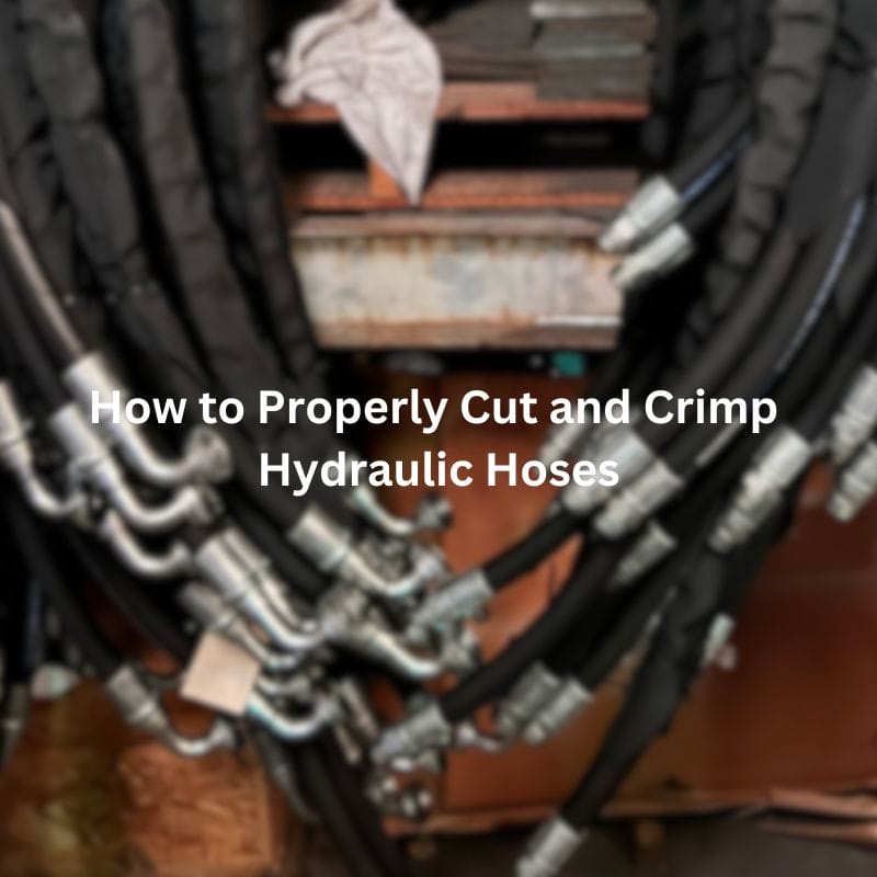
How to Properly Cut and Crimp Hydraulic Hoses Table of
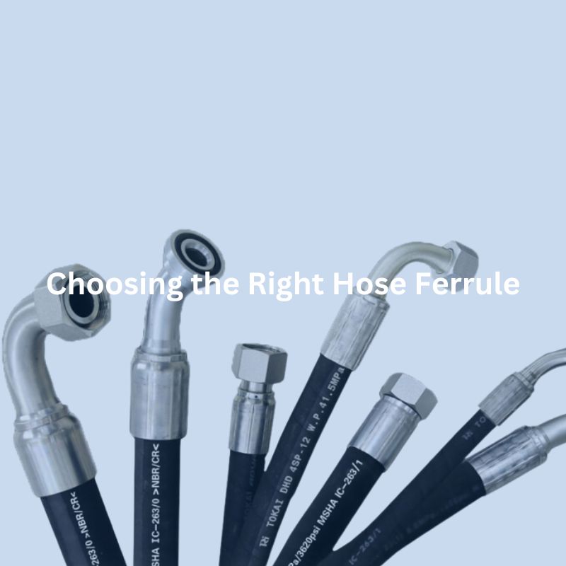
Choosing the Right Hose Ferrules: What You Need to Know
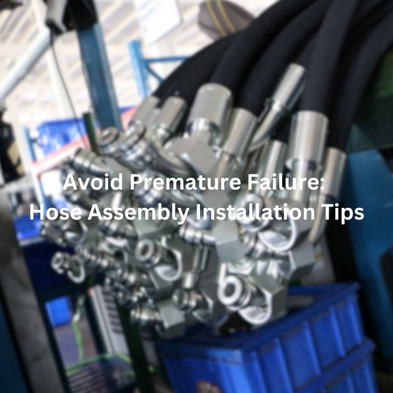
Avoid Premature Failure: Hose Assembly Installation Tips Contact Us Table

Why Hydraulic Flanges Prevent Leaks in Tough Systems Contact Us
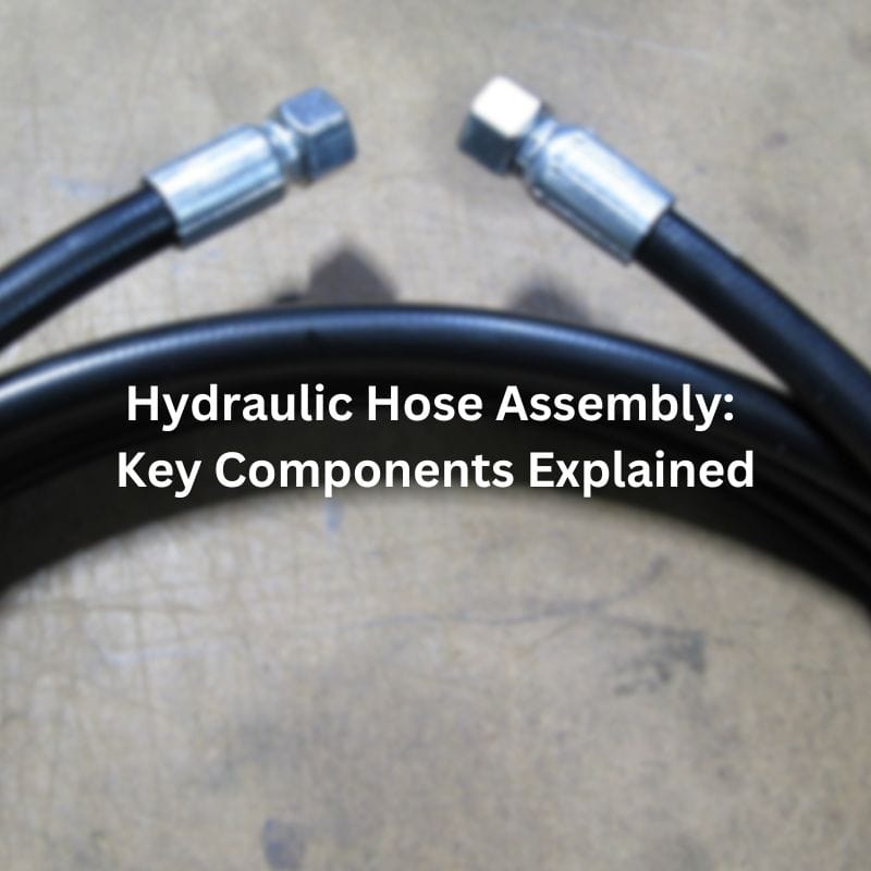
Hydraulic Hose Assembly: Key Components Explained Contact Us Table of

Preventing Leaks in Hydraulic Hose Assemblies Contact Us Table of

When and Why Should You Use Hydraulic Flanges Contact Us

Hydraulic Adapter Repair: How to Identify and Fix Contact Us

Hydraulic Adapter Failure: Causes and How to Prevent Contact Us