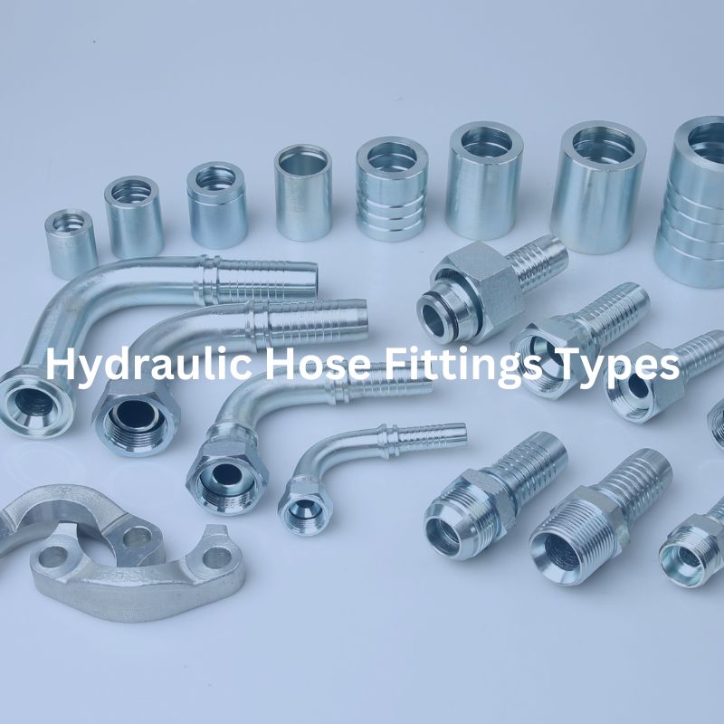
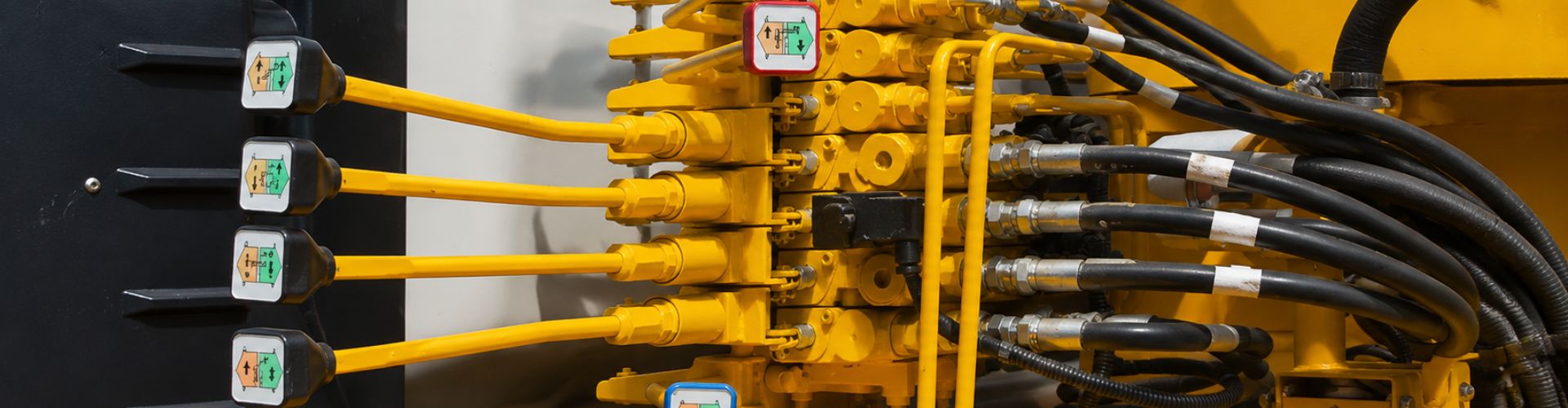
How to Install Braided Hose Fittings

How to Install Braided Hose Fittings

How to Install Braided Hose Fittings

Introduction

Installing braided hose fitting is a crucial skill for anyone working with hydraulic systems or automotive applications. These systems rely on precise and reliable connections to function optimally, and even a minor leak can lead to significant issues, including system failures, reduced efficiency, and costly downtime. Proper installation of braided hose fitting ensures that fluids are transported without leaks or interruptions, maintaining system pressure and performance. This guide provides a comprehensive, step-by-step process for installing braided fittings. It covers everything from selecting the right tools and materials to advanced techniques and troubleshooting tips.

Overview of Braided Hose Fitting

Braided fittings are a staple in hydraulic systems and automotive applications, prized for their exceptional durability and flexibility. These fittings are engineered to secure the hose to connection points firmly, ensuring a leak-proof and robust connection that withstands various operational stresses. Braided hoses, available in different materials, are tailored to meet specific application needs, with nylon and steel being the most prevalent choices.

Nylon Braided Hoses:

Flexibility and Ease of Handling: Nylon braided hoses are renowned for their flexibility, making them easy to route through tight spaces and around complex configurations. This attribute makes them particularly suitable for lower pressure applications where ease of installation is a priority.

Ease of Installation: Their flexibility also means that nylon braided hoses are simpler to install, reducing the time and effort required compared to more rigid alternatives.

Steel Braided Hoses:

Durability and High Pressure Handling: Steel braided hoses are built to endure high pressures and harsh operating conditions. This robustness makes them ideal for heavy-duty applications where reliability and performance are critical.

Precise Cutting for Secure Fit: Due to their construction, steel braided hoses require precise cutting techniques to avoid fraying and ensure a secure fit. This precision is crucial for maintaining the integrity of the hose and the system it serves.

Install Braided Hose Fittings

Importance in Hydraulic Systems and Automotive Applications

Braided fittings are essential components that contribute significantly to the performance and reliability of hydraulic systems and automotive applications. They ensure that fluids flow smoothly and consistently without leaks, which is critical for maintaining system pressure and preventing contamination. Proper installation of these fittings is vital to avoid potential system failures, which can lead to safety hazards, operational inefficiencies, and costly downtime.

Tools and Materials Needed

Essential Tools

Hose Cutters: These are crucial for making clean and precise cuts on the braided hose. Using the correct hose cutters ensures that the hose is cut evenly, minimizing the risk of fraying and ensuring a smooth assembly process.

AN Fitting Wrenches: Specifically designed for AN fittings, these wrenches prevent damage to the fittings during installation. Regular wrenches can cause scratches and deformation, so using AN fitting wrenches ensures a secure and damage-free fit.

Deburring Tool: After cutting the hose, it’s important to remove any sharp edges or burrs that could damage the fitting or compromise the connection. A deburring tool helps to smooth out the cut end of the hose, ensuring a clean and safe installation.

Masking Tape: Applying masking tape around the cut area helps to prevent the braided hose from fraying. This simple step makes the cutting process cleaner and the assembly easier.

Materials

Nylon or Steel Braided Hose: Select the type of hose based on your specific application requirements. Nylon braided hoses offer flexibility and ease of handling, making them suitable for lower-pressure applications. Steel braided hoses, on the other hand, are more durable and can withstand higher pressures, making them ideal for heavy-duty applications.

AN Fittings (appropriate size and type): Ensure that you have the right size and type of AN fittings compatible with your hose and system. Proper sizing and type selection are crucial for achieving a secure and leak-proof connection.

Lubricants (WD-40 or similar): Using a lubricant during the assembly process facilitates easier fitting insertion and prevents galling, which can damage the fittings and compromise the connection. Lubricants help ensure a smooth and trouble-free assembly.

Step-by-Step Installation Process for Braided Hoses

Preparation

Measure the Hose Length and Mark the Cut Point:

Use a tape measure: Carefully measure the length of the braided hose required for your specific application. Accurate measurement is crucial to ensure the hose fits perfectly within your system without excess slack or being too tight.

Mark the cut point: Once you have the exact length, use a marker to mark the cut point on the hose. This mark will guide you during the cutting process, ensuring precision and consistency.

Wrap the Cut Area with Masking Tape:

Wrap a strip of masking tape: Before cutting, wrap a strip of masking tape around the area where you plan to cut. This helps to stabilize the braided strands and prevent them from fraying during the cutting process, which can complicate assembly and compromise the hose’s integrity.

install PTFE fitting Topa

Cutting the Hose

Use Hose Cutters to Make a Clean Cut:

Position the hose cutters: Align the hose cutters at the marked point on the hose. Ensure the cutters are sharp and specifically designed for cutting braided hoses to achieve a clean and precise cut.

Make a clean, straight cut: Apply steady pressure to make a clean, straight cut through the hose. A smooth edge is crucial for a proper fitting connection, reducing the risk of leaks and ensuring a secure fit.

Deburr the Cut End to Remove Sharp Edges:

Use a deburring tool: After cutting, use a deburring tool to smooth out the cut end of the hose. This step removes any sharp edges or burrs that could damage the fitting or impede the assembly process.

Remove sharp edges and burrs: Carefully inspect the cut end and ensure all sharp edges and burrs are eliminated. This creates a smooth, even surface that facilitates a tight seal and prevents potential damage to the fitting components.

Fitting Assembly

Separate the AN Fitting into Its Components (Socket and Nipple):

Disassemble the Fitting: Take the AN fitting and separate it into its two main components: the socket and the nipple. This separation is necessary to properly insert the hose into the fitting.

Insert the Hose into the Fitting Socket Until It Bottoms Out:

Push the Hose into the Socket: Insert the hose into the fitting socket, pushing it in until it bottoms out. Ensure the hose is fully seated in the socket, as this will provide a secure base for the connection.

Lubricate the Fitting Nipple and Insert It into the Hose Socket:

Apply Lubricant: Apply a small amount of lubricant, such as WD-40, to the fitting nipple. This lubrication will make it easier to insert the nipple into the hose socket and prevent galling.

Insert the Nipple: Carefully insert the lubricated nipple into the hose socket. Ensure it goes in smoothly and is properly aligned.

Hand-Tighten the Nipple into the Socket:

Initial Tightening: Initially tighten the nipple by hand to ensure it is properly aligned and to avoid cross-threading. Hand-tightening allows you to feel the fitting coming together correctly before using tools.

Securing the Connection

Use AN Fitting Wrenches to Tighten the Connection:

Fully Tighten the Connection: Use AN fitting wrenches to fully tighten the connection. These wrenches are specifically designed to prevent damage to the fittings.

Avoid Over-Tightening: Be careful not to over-tighten the connection, as this can damage the fitting and compromise the seal. Tighten just enough to ensure a secure, leak-proof connection.

Ensure No Gaps Between the Fitting Components:

Verify Tightness: Inspect the connection to ensure there are no visible gaps between the fitting components. A proper fit is essential for a leak-proof connection and the overall integrity of the assembly.

Check for Any Fraying or Misalignment:

Inspect the Assembly: After tightening the connection, thoroughly inspect the hose and fittings for any signs of fraying or misalignment. Ensure that the hose is securely inserted and the fittings are properly aligned.

Make Adjustments if Necessary: If you notice any fraying or misalignment, make the necessary adjustments to correct the issue before putting the hose into service.

Tips for Different Hose Types

Nylon Braided Hoses

Advantage: Nylon braided hoses are highly flexible, making them easier to bend and route through tight spaces and complex configurations. This flexibility can simplify the installation process and reduce the effort needed to position the hose correctly.

Application: These hoses are particularly suitable for applications where space constraints require tight bends or intricate routing.

Requires Careful Handling to Avoid Kinking:

Caution: Despite their flexibility, nylon hoses can kink if handled roughly or bent excessively. Kinking can compromise the integrity of the hose, leading to potential leaks or system failures.

Tip: Handle the hose gently and avoid sharp bends. Use gradual curves instead of tight angles to maintain the hose’s integrity and performance.

Steel Braided Hoses

Advantage: Steel braided hoses are exceptionally durable and can withstand high pressures and harsh conditions. This makes them ideal for heavy-duty applications where reliability and performance are critical.

Application: These hoses are best suited for high-pressure hydraulic systems and other demanding environments where strength and durability are paramount.

Requires Precise Cutting to Avoid Fraying:

Caution: Cutting steel braided hoses can be challenging due to the risk of fraying. Frayed ends can make it difficult to insert the hose into the fitting and can compromise the connection’s integrity.

Tip: Use sharp, high-quality hose cutters designed for steel braided hoses to ensure clean, precise cuts. Wrapping the cut area with masking tape before cutting can also help prevent fraying. After cutting, inspect the hose end and trim any frayed strands to ensure a smooth and clean insertion into the fitting.

Advanced Techniques and Troubleshooting

Using Heat Shrink for Added Protection

Application of Heat Shrink Tubing Over the Fitting:

Slide Heat Shrink Tubing Over the Fitting: Before final assembly, slide a piece of heat shrink tubing over the hose, positioning it so it will cover the fitting once the assembly is complete.

Apply Heat to Secure It: After the fitting is assembled and tightened, slide the heat shrink tubing over the fitting area. Use a heat gun to evenly apply heat around the tubing. The tubing will shrink tightly around the fitting, providing a secure and protective layer.

Benefits for Durability and Appearance:

Additional Protection: Heat shrink tubing adds an extra layer of protection to the fitting, shielding it from external elements such as abrasion, moisture, and chemicals. This prolongs the life of the hose assembly.

Neat Appearance: The tubing also provides a clean and professional appearance, covering any imperfections and ensuring the installation looks tidy and well-finished.

grease An fitting Topa

Common Installation Issues

Leaks Due to Improper Tightening:

Ensure Fittings Are Adequately Tightened: One of the most common issues is leakage due to fittings not being tightened sufficiently. Use AN fitting wrenches to achieve the correct tightness, ensuring a secure and leak-proof connection.

Regular Inspection: Periodically check fittings for tightness, especially in high-vibration environments, to ensure they remain secure.

Hose Fraying or Kinking During Installation:

Use Masking Tape and Proper Cutting Techniques: To prevent fraying, always wrap the cut area with masking tape before cutting. Use sharp hose cutters to ensure a clean cut.

Handle with Care: Be gentle when routing and installing the hose to avoid kinking. Make sure to use gradual curves rather than sharp bends.

Solutions and Preventive Measures

Proper Lubrication:

Use Lubricants to Facilitate Smoother Fitting Assembly: Apply a small amount of lubricant (e.g., WD-40) to the fitting nipple and hose interior. This makes it easier to insert the fitting and reduces the risk of damage during assembly.

Prevent Galling: Lubrication helps to prevent galling (friction-induced damage) between metal surfaces, ensuring a smooth and secure fit.

Correct Tool Usage:

Use Appropriate Tools to Avoid Damaging the Hose or Fittings: Always use tools specifically designed for the job, such as AN fitting wrenches and hose cutters. Using improper tools can damage the hose or fittings, leading to leaks and other issues.

Follow Manufacturer Guidelines: Adhere to the manufacturer’s guidelines for tool use and fitting installation to ensure optimal results.

Conclusion

Installing braided hose fitting correctly is essential for the efficient and safe operation of hydraulic and automotive systems. Following the outlined steps and best practices ensures a secure, leak-proof connection, enhancing system performance and longevity. Always prioritize safety, use the right tools and materials, and adhere to manufacturer guidelines to achieve the best results.

FAQ

Masking tape is wrapped around the cut point to prevent the braided strands from fraying during the cutting process, ensuring a clean and smooth edge.

AN fittings should be tightened until they are snug and secure, but not over-tightened. Over-tightening can damage the fitting and compromise the seal. Use AN fitting wrenches for precise tightening.

It is not recommended to use regular wrenches as they can damage the fittings. AN fitting wrenches are specifically designed to fit the fittings properly and prevent damage.

If you notice fraying, stop and use a deburring tool to smooth out the cut end. Wrapping the cut area with masking tape before cutting can help prevent fraying in the first place.

Lubrication helps to facilitate smoother fitting assembly and prevents galling, which can damage the fittings. It ensures a secure and tight fit.

Handle the hose gently and avoid sharp bends. Use gradual curves when routing the hose and make sure not to bend it excessively to maintain its integrity and prevent kinking.

How to Loosen Hydraulic Hose Fittings

How to Loosen Hydraulic Hose Fittings

How to Loosen Hydraulic Hose Fittings

Table of Contents

Introduction

Hydraulic hose fittings are crucial components in various industrial applications, ensuring the proper flow of hydraulic fluid within the system. Proper maintenance and handling of these fittings are essential to avoid operational issues and extend the lifespan of the equipment. This guide aims to provide a comprehensive method for safely loosening hydraulic hose fittings, targeted towards maintenance providers, technicians, and industry professionals.

Understanding Hydraulic Hose Fittings

Types of Hydraulic Hose Fittings

Hydraulic hose fittings are essential components in hydraulic systems, ensuring secure connections and the efficient transfer of fluids. Each type of fitting is designed for specific applications and operating conditions, and understanding these types can help you choose the right fitting for your needs.

JIC Fittings:

JIC fittings are characterized by their 37-degree flare seating surface, which provides a strong and reliable connection. These fittings are widely used in fuel delivery systems, fluid power applications, and other high-pressure environments where durability and reliability are crucial. Their flared design ensures a tight seal, reducing the risk of leaks and enhancing system safety.

ORFS Fittings:

ORFS fittings feature an O-ring within a groove on the face of the fitting, creating a seal when connected. This design ensures a leak-proof connection, even under high-pressure conditions. Ideal for high-pressure hydraulic systems, ORFS fittings are commonly used in construction equipment, agricultural machinery, and other industrial applications requiring reliable sealing. The primary benefit of ORFS fittings is their ability to provide a leak-proof seal, significantly reducing the risk of fluid leaks. This makes them suitable for applications where maintaining hydraulic fluid integrity is critical.

NPT Fittings:

NPT fittings use a tapered thread design that tightens as it is threaded together, creating a seal. NPT fittings are commonly used in lower-pressure applications such as pneumatic systems, plumbing, and general hydraulic systems where high pressure is not a primary concern.

BSP Fittings:

BSP fittings are similar to NPT fittings but have a different thread angle and pitch. BSP fittings are commonly used in Europe and Asia and come in two types: BSPP (parallel) and BSPT (tapered). These fittings are widely used in hydraulic systems, plumbing, and other fluid transfer applications in regions where BSP standards are prevalent.

Preparatory Steps Before Loosening Fittings

Safety Precautions

When working with hydraulic systems, safety is paramount. Improper handling can lead to severe injuries or system damage. Always follow these guidelines to ensure a safe and efficient work environment:

Wear Personal Protective Equipment (PPE):

  • Gloves: Protect your hands from sharp edges and hot surfaces.
  • Safety Goggles: Shield your eyes from hydraulic fluid splashes and debris.
  • Protective Clothing: Wear long sleeves and pants to minimize skin exposure to hydraulic fluid and other hazards.
  • Ensure a Safe Working Environment:
  • Clear the Area: Remove any unnecessary personnel and equipment from the work area to prevent accidents.
  • Adequate Lighting: Ensure the work area is well-lit to avoid mistakes and to see potential hazards.
  • Ventilation: Work in a well-ventilated area to avoid inhaling fumes from hydraulic fluids and lubricants.

Tools and Equipment Needed

Having the right tools and equipment is essential for safely and effectively loosening hydraulic hose fittings. The proper tools not only make the job easier but also help prevent damage to the fittings and the hydraulic system. Here’s a list of essential tools and equipment:

Wrenches:

  • Adjustable Wrenches: Versatile and can be adjusted to fit different sizes of fittings.
  • Pipe Wrenches: Useful for gripping round fittings and applying significant torque.
  • Specific Hydraulic Wrenches: Designed specifically for hydraulic fittings, ensuring a better grip and preventing damage.

Pliers:

  • Slip-Joint Pliers: Adjustable pliers that can be used for gripping various sizes of fittings.
  • Needle-nose Pliers: Ideal for gripping small fittings and working in tight spaces.
  • Locking Pliers (Vise-Grips): Provide a firm grip on the fitting, making it easier to turn.

Lubricants:

  • Penetrating Oils: Products like WD-40 or PB Blaster can help loosen rusted or seized fittings by penetrating the threads and breaking down corrosion.
  • Application: Apply the penetrating oil around the fitting and allow it to sit for several minutes to maximize effectiveness.

Step-by-Step Guide to Loosening Hydraulic Hose Fittings

Initial Assessment

Before attempting to loosen a hydraulic hose fitting, a thorough initial assessment is crucial. This step helps you understand the condition of the fitting and select the appropriate tools for the job.

Inspect for Damage or Corrosion:

  • Visual Inspection: Look for signs of wear, rust, or corrosion. These can make the fitting harder to loosen and might indicate that additional care is needed.
  • Physical Examination: Feel for any roughness or deformities that might suggest damage beyond visual inspection.

Determine Type and Size:

  • Identify the Fitting Type: Understand whether it is a JIC, ORFS, NPT, BSP, or another type of fitting. This will guide the choice of tools and techniques.
  • Measure the Fitting: Use a caliper or a fitting gauge to determine the exact size of the fitting, ensuring you select tools that fit properly.

Applying Lubricants and Penetrating Oils

Lubricants and penetrating oils can significantly ease the process of loosening hydraulic hose fittings by breaking down rust and corrosion.

Types of Lubricants:

  • Penetrating Oils: Products like WD-40, PB Blaster, and Liquid Wrench are designed to penetrate rust and corrosion, making it easier to loosen fittings.
  • Specialty Lubricants: Consider using high-performance penetrating lubricants for severely corroded or seized fittings.

Application:

  • Apply Generously: Spray or apply the lubricant around the fitting, ensuring it reaches the threads.
  • Wait Time: Allow the lubricant to penetrate for several minutes. For severely seized fittings, let it sit for up to an hour, reapplying as needed.

Loosening Techniques

Using the right techniques is essential to avoid damaging the fitting or the hydraulic system.

Gentle Tapping and Vibration:

  • Light Tapping: Use a small hammer to gently tap the fitting. This can help break the bond of rust or corrosion.
  • Vibration: Apply vibration using a vibrating tool or by tapping consistently to loosen the grip of corrosion on the threads.

Using Heat:

  • Heat Application: Use a heat gun or propane torch to apply heat around the fitting. Heat causes the metal to expand, which can break the bond of rust and make the fitting easier to loosen.
  • Caution: Avoid overheating, which can damage the fitting or surrounding components. Heat should be applied evenly and for short periods.
stuck Hydraulic fitting

Step-by-Step Process

Apply Moderate Force:

  • Initial Attempt: Begin by applying moderate force using the appropriate wrench or pliers. Ensure you have a firm grip on the fitting to avoid slippage.
  • Caution: Do not apply excessive force immediately, as this can damage the fitting or strip the threads, making it even more difficult to remove. Gentle but firm pressure is key.

Increase Gradually:

  • Incremental Pressure: If the fitting does not budge with moderate force, gradually increase the pressure. This approach minimizes the risk of sudden breakage or thread damage.
  • Lubricant Application: If the fitting remains resistant, apply additional penetrating oil or lubricant. Allow the lubricant to penetrate for several minutes before attempting to loosen the fitting again.
  • Tapping Technique: Use a small hammer to gently tap around the fitting. The vibration can help break up rust and corrosion, making the fitting easier to turn. Alternate between applying lubricant and tapping to maximize the effect.

Dealing with Stubborn Fittings

Sometimes, despite careful application of force and lubrication, hydraulic hose fittings remain stubborn due to severe corrosion or being over-tightened. In these cases, more advanced techniques are necessary.

Advanced Techniques

Hydraulic Pullers:

  • Usage: Hydraulic pullers or extractors are designed to remove seized fittings by applying uniform, controlled force. Attach the puller to the fitting and operate it according to the manufacturer’s instructions.
  • Effectiveness: These tools can be very effective, especially for fittings that are deeply corroded or tightly bonded to the hose.

Impact Tools:

  • Pneumatic Impact Tools: These tools use compressed air to deliver high torque and vibration, which can help break the bond of rust and corrosion. Attach the impact tool to the fitting and use short, controlled bursts.
  • Electric Impact Tools: Similar to pneumatic tools, electric impact tools provide high torque and vibration. They are useful in situations where compressed air is not available. Always follow safety guidelines when using impact tools to avoid damage or injury.
stubborn Hydraulic fitting Topa

Cutting and Replacing

When Necessary:

  • Last Resort: If all other methods fail, cutting the fitting may be the only viable option. This should be considered a last resort due to the irreversible nature of cutting.
  • Tool Selection: Use a pipe cutter, hacksaw, or reciprocating saw. Choose the tool based on the material of the fitting and the surrounding components to avoid collateral damage.

Cutting Process:

  • Careful Execution: Position the cutter or saw carefully to ensure a clean cut through the fitting without damaging the hose or other adjacent components. It is crucial to maintain steady hands and a slow, controlled cutting motion.
  • Removing the Fitting: Once the fitting is cut through, gently remove it. Be mindful of any remaining sharp edges that could pose a safety hazard.

Replacement:

  • Selecting a New Fitting: Ensure the replacement fitting matches the specifications of the original, including thread type, size, and material. This is essential for maintaining system integrity and preventing leaks.
  • Installation: Install the new fitting according to the manufacturer’s guidelines. Use proper torque specifications to avoid over-tightening and ensure a secure, leak-free connection.
  • Testing: After installation, repressurize the hydraulic system and test for leaks. Conduct a thorough inspection to confirm that the new fitting is securely in place and functioning correctly.

Post-Loosening Procedures

After successfully loosening and removing a hydraulic hose fitting, several critical steps must be taken to ensure the system’s integrity and prevent future issues. This section covers inspecting the fitting and hose, cleaning and maintenance, reconnecting the system, and system testing.

Inspecting the Fitting and Hose

Checking for Signs of Damage or Wear:

  • Visual Inspection: Carefully examine the removed fitting for any signs of damage, such as cracks, deformation, or excessive corrosion. These issues can indicate that the fitting needs to be replaced rather than reused.
  • Thread Integrity: Inspect the threads for any signs of stripping or cross-threading. Damaged threads can compromise the sealing capability and should be addressed.
  • Hose Condition: Check the hose for any signs of wear, such as abrasions, cuts, or bulges. These can indicate potential failure points that need attention.

Assessing the Condition of the Hose and Adjacent Fittings:

  • Hose Integrity: Ensure the hose is still flexible and free of cracks. Stiffness or brittleness in the hose material can indicate age-related degradation and may necessitate replacement.
  • Adjacent Fittings: Inspect any nearby fittings for similar issues. Corrosion or damage to adjacent fittings can impact the overall system’s performance and safety.

Cleaning and Maintenance

Cleaning the Fitting and Surrounding Area:

  • Debris Removal: Use a suitable solvent to clean the fitting and the surrounding area thoroughly. Remove any dirt, rust, or debris that could interfere with the connection.
  • Drying: Ensure the cleaned areas are completely dry before proceeding to prevent any contaminants from entering the hydraulic system.

Applying Anti-Seize Compounds:

  • Purpose: Applying an anti-seize compound to the threads of the fitting can prevent future seizing and make future maintenance easier.
  • Application: Apply a thin, even layer of anti-seize compound to the threads of the fitting. Avoid over-application, as excess compounds can contaminate the hydraulic fluid.

Reconnecting the System

Proper Reinstallation Techniques:

  • Alignment: Ensure the fitting and hose are correctly aligned before threading the fitting. Misalignment can lead to cross-threading and damage.
  • Thread Engagement: Start threading the fitting by hand to ensure proper engagement and avoid cross-threading. Once hand-tight, use the appropriate wrench to secure the fitting.

Ensuring Secure and Leak-Free Connections:

  • Torque Specifications: Follow the manufacturer’s recommended torque specifications to ensure the fitting is tightened correctly. Over-tightening can damage the threads, while under-tightening can lead to leaks.
  • Sealing Elements: Ensure any O-rings, gaskets, or sealing elements are correctly positioned and in good condition. Replace any worn or damaged seals.

System Testing

Repressurizing the Hydraulic System:

  • Gradual Pressurization: Slowly bring the hydraulic system back up to its operating pressure. This gradual approach allows for monitoring and immediate response to any issues.
  • Monitoring: Keep a close eye on the system during depressurization, looking for any signs of leaks or pressure drops.

Testing for Leaks and Proper Functionality:

  • Leak Detection: Use a leak detection fluid or soapy water to check for leaks around the reconnected fitting. Bubbles or fluid movement indicates a leak that needs to be addressed.
  • System Functionality: Test the hydraulic system under normal operating conditions to ensure it is functioning correctly. Pay attention to any unusual noises, vibrations, or performance issues.
  • Final Inspection: After the system has been tested and deemed functional, perform a final inspection of all fittings and connections to ensure everything is secure and leak-free.

Conclusion

To safely and effectively loosen hydraulic hose fittings, it’s crucial to follow proper procedures, including initial assessment, selecting the right tools, applying lubricants, and employing appropriate loosening techniques. Always adhere to safety measures and use the correct tools to avoid damage. Regular maintenance and inspections are vital to ensure the longevity and reliability of your hydraulic system.

For more information, refer to industry books, articles, and online resources. Contact Topa hydraulic system experts for professional advice and assistance.

FAQ

How do I identify the type of hydraulic hose fitting?

Check the shape, size, and thread type of the fitting. Common types include JIC, ORFS, NPT, and BSP. Refer to manufacturer specifications or use a fitting gauge for accurate identification.

What should I do if a hydraulic hose fitting is stuck?

Apply penetrating oil, allow it to sit, then use appropriate tools with moderate force. If still stuck, use heat carefully or advanced tools like hydraulic pullers.

How can I prevent hydraulic hose fittings from seizing in the future?

Regularly apply anti-seize compounds to the threads, maintain a clean environment, and perform routine inspections and maintenance.

What safety precautions should I take when working with hydraulic systems?

Always wear PPE, such as gloves, safety goggles, and protective clothing. Ensure the work area is clear and well-lit, and depressurize the system before starting any work.

How do I check for leaks after reconnecting a hydraulic hose fitting?

Gradually repressurize the system and use a leak detection fluid or soapy water around the fitting. Look for bubbles or fluid movement indicating a leak.

When should I replace a hydraulic hose fitting instead of reusing it?

Replace the fitting if it shows signs of severe damage, corrosion, or stripped threads, or if it fails to seal properly after reinstallation.

Hydraulic Hose Fitting Repair Expert Tips for Quick Fixes

Hydraulic Hose Fitting Repair: Expert Tips for Quick Fixes

Hydraulic Hose Fitting Repair: Expert Tips for Quick Fixes

Table of Contents

Introduction

Hydraulic hose fittings are crucial components in various industrial applications, ensuring the efficient transfer of fluids under high pressure. When these fittings fail, the consequences can be severe, leading to costly downtime and potential safety hazards. Understanding how to quickly and effectively repair hydraulic hose fittings is essential for maintaining productivity and safety. This post aims to provide expert tips for both immediate on-site fixes and long-term repair solutions, helping you minimize downtime and maintain optimal performance in your hydraulic systems.

Understanding Hydraulic Hose Fittings

Hydraulic hose fittings are integral components in hydraulic systems, designed to connect hoses to various system parts such as pumps, valves, and cylinders. These fittings ensure the seamless flow of hydraulic fluid under high pressure, enabling the system to function effectively and efficiently. Given their critical role, understanding the different types of fittings and the common causes of their failures is essential for maintaining the reliability of hydraulic systems.

Common Causes of Hose Fitting Failures

Understanding the common causes of hose fitting failures can help in preventing issues and ensuring the longevity of hydraulic systems:

Wear and Tear:

Over time, hydraulic hose fittings are subjected to repeated use and exposure to harsh conditions, leading to gradual degradation. Factors such as friction, pressure cycles, and environmental exposure contribute to wear and tear, eventually causing fittings to weaken and fail.

Improper Installation:

Incorrect installation practices are a significant cause of premature fitting failure. This includes using the wrong type of fitting, not following manufacturer guidelines, or not ensuring a secure and tight connection. Improper installation can lead to leaks, reduced system efficiency, and increased risk of fitting blowouts.

Environmental Factors:

Hydraulic hose fittings are often exposed to extreme environmental conditions, including temperature fluctuations, chemicals, and physical abrasion. High temperatures can cause fittings to expand and contract, leading to material fatigue. Exposure to chemicals can cause corrosion, while physical abrasion can wear down the surface of the fittings, compromising their integrity.

leaking hydraulic Fittings Topa

Signs of Failing Hose Fittings

Recognizing the signs of failing hose fittings is essential for timely maintenance and repair, preventing more severe system failures:

Leaks:

Visible fluid leakage around the fitting area is a clear indicator of fitting failure. Leaks can occur due to cracks, loose connections, or damaged sealing surfaces. Regular inspection for leaks can help identify problems early and prevent fluid loss and contamination.

Pressure Drops:

A sudden drop in system pressure suggests a problem with the hydraulic hose fittings. Pressure drops can occur when there is a partial blockage, a significant leak, or a fitting that is not securely connected. Monitoring system pressure can help detect issues before they lead to complete system failure.

Visible Damage:

Cracks, corrosion, or other visible damage to the fittings indicate the need for repair or replacement. Regular visual inspections of the fittings and hoses can help identify signs of damage early. Look for any signs of wear, rust, or deformation that could compromise the fitting’s performance.

Quick Fixes for On-Site Hydraulic Hose Fitting Repair

In many situations, the ability to perform quick fixes on hydraulic hose fittings can be the difference between significant downtime and continued operation. These temporary repairs are essential to keep operations running smoothly until a more permanent solution can be implemented.

Temporary Repairs

Temporary repairs are critical for immediate issues that arise unexpectedly. Here are two effective methods for quick on-site repairs:

Using Hose Clamps:

Hose clamps are a reliable and straightforward solution for temporarily stopping leaks in hydraulic hoses. When a leak is detected, placing a hose clamp over the affected area can help contain the fluid and prevent further leakage. Here’s how to use hose clamps effectively:

Selection: Choose a clamp that fits the diameter of the hose snugly.

Placement: Position the clamp directly over the leak.

Tightening: Use a screwdriver or wrench to tighten the clamp until the leak is stopped. Be careful not to over-tighten, as this can damage the hose further.

Applying Sealants and Tapes:

Hydraulic sealants and self-fusing silicone tapes are excellent for quickly patching minor leaks. These materials are designed to withstand high pressure and create a temporary seal that prevents fluid from escaping.

Sealants: Apply hydraulic sealant around the leaking area, ensuring it covers the entire circumference of the hose. Allow the sealant to set as per the manufacturer’s instructions before testing the repair.

Silicone Tapes: Wrap self-fusing silicone tape tightly around the leak, overlapping each layer to ensure a secure seal. The tape bonds to itself, forming a durable, waterproof barrier.

repair Hydraulic hose Topa

Step-by-Step Guide for On-Site Quick Fixes

Implementing a quick fix requires careful attention to detail and adherence to safety protocols. Here’s a step-by-step guide to ensure effective and safe repairs:

Identifying the Problem:

  • Inspection: Begin by thoroughly inspecting the hose and fittings to locate the source of the issue. Look for visible signs of wear, damage, or fluid leakage.
  • Pressure Testing: If the leak is not immediately apparent, use a pressure testing kit to identify pressure drops that indicate a leak.

Preparing the Site and Equipment:

  • Depressurizing the System: Before starting any repair, ensure the hydraulic system is fully depressurized to prevent accidents. Turn off the hydraulic pump and bleed the pressure from the system using the appropriate valves.
  • Gathering Tools: Collect all necessary tools and materials for the repair, including hose clamps, sealants, silicone tape, wrenches, screwdrivers, and safety gear.

Implementing the Temporary Fix:

  • Safety First: Wear safety goggles, gloves, and protective clothing to safeguard against fluid exposure and potential injuries.
  • Applying the Fix: Depending on the chosen method, use hose clamps, sealant, or silicone tape to the damaged area. Ensure the application is thorough and secure.
  • Hose Clamps: Position the clamp over the leak and tighten it until the leak stops.
  • Sealants: Apply the sealant evenly around the leak and allow it to cure.
  • Silicone Tapes: Wrap the tape tightly around the hose, covering the leak completely.

Testing the Repair:

  • Repressurizing the System: Slowly repressurize the hydraulic system, monitoring the repaired area for any signs of leakage. Gradually increase the pressure to the operating level.
  • Checking for Leaks: Observe the repaired area closely to ensure the temporary fix is holding. If leaks persist, reapply the temporary fix or consider a different method.

Practical Tips for On-Site Repairs

  • Keep a Repair Kit Ready: Always have a well-stocked repair kit on hand that includes various sizes of hose clamps, sealants, tapes, and basic tools. This preparedness ensures you can address issues promptly.
  • Routine Inspections: Regularly inspect your hydraulic systems for early signs of wear and damage. Early detection can prevent minor issues from escalating into major failures.

Detailed Repair Procedures for Long-Term Solutions

For a more permanent solution to hydraulic hose fitting issues, it’s essential to follow detailed and precise repair procedures. These steps ensure the longevity and reliability of the repaired fittings, preventing future failures and maintaining system efficiency.

Removing and Replacing Damaged Hose Fittings

Proper Disconnection Techniques:

  • Depressurize the System: Before starting any repair, ensure the hydraulic system is completely depressurized to prevent accidents. Turn off the hydraulic pump and open the appropriate valves to release any residual pressure.
  • Clean the Area: Clean the area around the damaged fitting to remove dirt and debris. This ensures that no contaminants enter the hydraulic system during the repair process.
  • Use the Correct Tools: Gather the necessary tools, such as wrenches, pliers, and hose cutters. Use these tools to carefully disconnect the damaged fitting from the hose and the hydraulic system. Ensure you follow the manufacturer’s guidelines to avoid damaging the hose or other components.

Selecting the Right Replacement Fittings:

  • Match Specifications: Choose replacement fittings that match the exact specifications of your system, including size, thread type, and material. Using the correct fittings is crucial for ensuring a secure and leak-proof connection.
  • Quality Components: Invest in high-quality fittings from reputable manufacturers to ensure durability and reliability. Avoid cheap or substandard fittings that may fail prematurely.
fix hydraulic fitting Topa

Techniques for Permanent Hose Fitting Repairs

Crimping and Swaging:

  • Hydraulic Crimping Machine: Use a hydraulic crimping machine to securely attach new fittings to the hose. Follow these steps:
  • Cut the Hose: Use a hose cutter to make a clean, straight cut at the end of the hose where the new fitting will be attached.
  • Insert the Fitting: Insert the hose end into the fitting until it reaches the fitting’s stop.
  • Crimping Process: Place the hose and fitting assembly into the crimping machine and select the appropriate die set. Activate the crimping machine to compress the fitting onto the hose, ensuring a tight and secure connection.
  • Inspect the Crimp: After crimping, inspect the fitting to ensure it is properly seated and there are no visible gaps or misalignments.

Welding and Soldering:

  • When Necessary: In some cases, especially with metal fittings, welding or soldering may be required to repair or reinforce fittings. This is typically done when fittings are part of a larger metal assembly or when high-pressure applications demand additional strength.
  • Welding Process: Use appropriate welding techniques (such as TIG or MIG welding) to fuse the fitting to the hose or assembly. Ensure the weld is strong and free from defects.
  • Soldering Process: For smaller repairs, soldering may be used to join fittings. Heat the fitting and apply solder to create a secure bond. Allow the solder to cool and solidify before testing.

Reassembly and Testing

Ensuring a Secure Fit:

  • Reassemble Components: Carefully reassemble the new fittings onto the hose and reconnect them to the hydraulic system. Ensure all connections are tight and secure, following the manufacturer’s specifications.
  • Check Alignment: Verify that all components are properly aligned and that there is no strain on the hose or fittings. Misalignment can lead to premature wear and potential failures.

Pressure Testing for Leaks:

  • Conduct a Thorough Test: After reassembly, conduct a pressure test to confirm the integrity of the repair. Gradually increase the system pressure to the operating level while closely monitoring the repaired area for any signs of leaks.
  • Use a Pressure Gauge: Attach a pressure gauge to monitor the system pressure accurately. Ensure the pressure remains stable and within the specified range.
  • Inspect for Leaks: Visually inspect all connections and fittings for any signs of fluid leakage. If leaks are detected, depressurize the system and re-tighten the fittings or apply additional repairs as needed.
  • Final Verification: Once the system has been pressurized and no leaks are found, verify the overall performance of the hydraulic system. Ensure that it operates smoothly and efficiently, with no unusual noises or pressure fluctuations.

Conclusion

Hydraulic hose fitting repairs are an essential skill for maintaining the efficiency and safety of hydraulic systems. By understanding the causes of failures, having the right tools, and following expert tips for quick and permanent repairs, you can minimize downtime and ensure the longevity of your equipment. Implement these strategies to keep your operations running smoothly and effectively.

FAQ

How often should I inspect my hydraulic hose fittings?

It’s recommended to perform brief daily inspections, more thorough weekly inspections, and comprehensive monthly inspections to ensure early detection of wear, leaks, or other potential issues.

What are the signs of a failing hydraulic hose fitting?

Common signs include visible fluid leaks, sudden drops in system pressure, and visible damage such as cracks or corrosion on the fittings.

Can I perform hydraulic hose fitting repairs myself?

Yes, with the right tools and knowledge, you can perform temporary and even permanent repairs. However, for complex issues or if you’re unsure, it’s best to consult a professional.

What tools do I need for on-site hydraulic hose fitting repairs?

Basic tools include wrenches, screwdrivers, pliers, and a utility knife. Specialized equipment like a hydraulic crimping machine, hose cutters, and a pressure testing kit are also essential for more complex repairs.

How can I prevent hydraulic hose fitting failures?

Regular inspections, proper installation practices, using high-quality materials, and ensuring your team is well-trained in handling and maintenance procedures are key steps in preventing failures.

What should I do if I detect a leak in a hydraulic hose fitting?

Immediately depressurize the system, inspect the area to locate the leak, and apply a temporary fix such as a hose clamp or hydraulic sealant. Follow up with a permanent repair as soon as possible to ensure the system’s reliability.

How to Measure Hydraulic Hose Fittings

How to Measure Hydraulic Hose Fittings

How to Measure Hydraulic Hose Fittings

Table of Contents

Introduction

Accurate measurement of hydraulic hose fittings is critical to maintaining system integrity and preventing costly failures. Ensuring the correct size and type of fittings prevents leaks, enhances compatibility, and maintains system efficiency. Hydraulic fittings come in various types, including NPTF, SAE, and DIN, each serving specific applications like fluid power, automotive, and industrial machinery. Proper measurement involves using tools like calipers and thread pitch gauges to accurately determine dimensions, which helps in selecting the right fittings, thus avoiding mismatches that could lead to operational inefficiencies and safety hazards.

Step-by-Step Guide to Measuring Hydraulic Hose Fittings

Preparation

Clean the Fitting and Hose: Before starting, ensure that both the fitting and the hose are clean. Dirt and debris can interfere with accurate measurements and may damage the measuring tools.

Gather Necessary Tools: Assemble all required tools, including measuring tape, calipers (both ID and OD), a thread pitch gauge, and a protractor. Having these tools readily available will streamline the measurement process.

Safety Precautions: Wear appropriate personal protective equipment (PPE) such as gloves and safety glasses. Ensure that the hydraulic system is depressurized and disconnected to avoid accidental injury.

Measuring the Thread Size

Accurately measuring the thread size of hydraulic hose fittings is essential for ensuring proper fit and function within hydraulic systems. This process involves several key steps and considerations:

Using the Thread Pitch Gauge

Placement of the Gauge: Begin by placing the teeth of the thread pitch gauge onto the threads of the fitting. It’s crucial to achieve a tight fit, meaning there should be no gaps between the gauge and the threads. This ensures that the pitch is measured correctly.

Determining Thread Pitch: The thread pitch gauge helps to measure the distance between threads, known as the thread pitch. This measurement is vital for identifying the correct fitting size and type. The pitch is usually measured in threads per inch (TPI) for imperial threads or in millimeters for metric threads.

Ensuring Accuracy: Ensure the gauge is clean and free from debris before use, as dirt can cause inaccurate readings. Additionally, if the fitting is worn or damaged, it might be harder to get an accurate pitch measurement. In such cases, verify with multiple gauge sizes to find the best match.

plug gauge Topa

Handling Worn or Old Fittings

Challenges with Worn Fittings: Over time, fittings can become worn or damaged, which may affect the accuracy of your measurements. Wear and tear can alter the thread pitch slightly, leading to potential mismatches.

Use New Fittings for Best Results: For the most accurate measurements, it’s advisable to use new fittings whenever possible. New fittings will provide the most precise measurements, free from any distortions caused by wear.

Consult a Professional: If you encounter discrepancies or have doubts about the measurements, consulting with a professional can be very helpful. Experienced technicians can provide insights and confirm the correct size and type of fitting needed.

Tools and Techniques: In some cases, specialized tools and techniques, such as thread identification kits, can be employed to handle worn or old fittings. These kits often come with various gauges and charts that can help in accurately identifying the thread pitch despite wear.

Determining the Outside Diameter (OD)

Accurately determining the outside diameter (OD) of hydraulic hose fittings is crucial for ensuring a proper fit and function within hydraulic systems. This process involves using calipers and following precise measurement techniques to avoid errors and ensure reliability.

Calipers Usage Technique

Zero Out the Calipers: Before beginning the measurement process, it is essential to zero out the calipers. This ensures that the measurements start from a true zero point, avoiding any initial discrepancies. Digital calipers usually have a reset button for this purpose, while manual calipers can be adjusted manually.

Positioning the Fitting: Place the fitting between the jaws of the calipers. Ensure that the fitting is positioned correctly, with the calipers perpendicular to the axis of the fitting. This positioning is crucial to obtaining an accurate measurement, as any tilt or misalignment can result in incorrect readings.

Closing the Jaws: Gently close the jaws of the calipers around the fitting until they hold it tightly. Avoid applying excessive force, as this can deform the fitting or the calipers, leading to inaccurate measurements. The goal is to achieve a snug fit without any gaps.

Reading the Measurement: Once the calipers are correctly positioned and closed, read the measurement from the caliper scale. Digital calipers will display the measurement on a screen, while manual calipers require you to read from a vernier scale.

Multiple Measurement Approach for Accuracy

Measure at Multiple Points: To ensure accuracy and consistency, it is advisable to measure the outside diameter at several points around the fitting. This helps to identify any irregularities or variations in the fitting’s diameter. Typically, at least three measurements at different points around the circumference should be taken.

Ensuring Consistency: When taking multiple measurements, ensure that each measurement is performed in the same manner, with the calipers perpendicular to the fitting and zeroed out before each measurement. Consistency in the measurement technique helps to minimize errors.

Averaging the Measurements: Once multiple measurements have been taken, calculate the average of these measurements. Averaging helps to account for any slight variances and provides a more accurate representation of the fitting’s true outside diameter. For example, if the measurements taken are 20.2 mm, 20.3 mm, and 20.1 mm, the average would be (20.2 + 20.3 + 20.1) / 3 = 20.2 mm.

Recording the Results: Document the measurements and the calculated average for reference. Keeping a record of these measurements can be useful for future reference and for verifying the fitting’s specifications.

Calculating the Inside Diameter (ID)

Accurately calculating the inside diameter (ID) of hydraulic hose fittings is crucial for ensuring proper fit and functionality within hydraulic systems. This process involves using calipers to measure female threads and taking multiple measurements to ensure precision.

id measure Topa

Using Calipers for Female Threads

Inserting the Calipers: To measure the internal diameter of female threads, insert the jaws of the calipers inside the fitting. Ensure that the jaws are fully inserted and positioned correctly to capture the internal dimensions accurately.

Positioning for Precision: Make sure the calipers are positioned perpendicularly to the fitting walls to get precise readings. The jaws should be evenly aligned within the fitting without any tilt or misalignment, which could lead to inaccurate measurements.

Reading the Measurement: Once the calipers are properly positioned, gently close the jaws until they touch the internal walls of the fitting. Read the measurement displayed on the calipers. For digital calipers, the reading will be shown on the screen, while for manual calipers, you will need to read the measurement from the vernier scale.

Ensuring Precise Readings

Taking Multiple Measurements: To ensure accuracy, take multiple measurements at different points within the fitting. This step is particularly crucial for fittings that have experienced wear and tear, as the internal diameter may not be uniform. Measure at least three different points along the circumference of the fitting.

Consistency in Technique: Maintain consistency in your measurement technique. Each time you measure, ensure the calipers are zeroed out and positioned perpendicularly within the fitting. Consistency helps minimize measurement errors.

Calculating the Average: After taking multiple measurements, calculate the average of these readings to obtain the most accurate internal diameter. For instance, if the measurements are 15.1 mm, 15.2 mm, and 15.0 mm, the average would be (15.1 + 15.2 + 15.0) / 3 = 15.1 mm.

Evaluating the Thread Pitch

Accurately evaluating the thread pitch of hydraulic hose fittings is essential for ensuring compatibility and proper function within hydraulic systems. This process involves using a thread pitch gauge or alternative methods to measure the distance between threads.

Thread Pitch Gauge Application

Placement of the Gauge: To determine the thread pitch, start by placing the teeth of the thread pitch gauge onto the fitting threads. Ensure the gauge fits snugly without gaps between the gauge teeth and the threads. This snug fit is crucial for obtaining an accurate measurement.

Measuring the Pitch: The thread pitch gauge helps measure the distance between the threads, known as the pitch. The pitch is typically measured in threads per inch (TPI) for imperial measurements or in millimeters for metric measurements. It indicates how many threads are in a given unit length.

Matching with Standardized Charts: Once the pitch is measured, compare it with standard thread identification charts from fitting manufacturers. These charts will help you identify the specific type and size of the thread, such as NPT, BSP, or JIC threads. Accurate identification is vital for selecting compatible fittings.

Thread pitch

Alternative Methods Without a Pitch Gauge

Using Calipers for Manual Measurement: If a thread pitch gauge is unavailable, you can manually measure the thread pitch using calipers. This method involves counting the number of threads within a specific length.

Counting Threads per Inch: For imperial measurements, count the number of threads within a one-inch span using calipers. Align the calipers with the start of the thread and count the number of full threads within one inch. This count gives you the threads per inch (TPI).

Converting to Metric: If you need to convert the measurement to metric, use the conversion factor where 1 inch equals 25.4 millimeters. Measure the distance for a known number of threads and then divide by the number of threads to find the pitch in millimeters.

Estimating the Fitting Angle

Accurately estimating the fitting angle is crucial for selecting the appropriate hydraulic fittings, ensuring system compatibility and optimal performance. This process involves using a protractor and understanding the significance of common fitting angles.

Protractor Usage

Using a Protractor: To measure the angle of the fitting, place the protractor along the axis of the fitting. Align one side of the fitting with the zero line of the protractor. Make sure the fitting is stable and correctly positioned for an accurate reading.

Measuring the Angle: Read the angle from the protractor where the other side of the fitting aligns with the degree markings on the protractor. The most common fitting angles are 45°, 90°, and occasionally 22.5°. Ensure that you take the measurement carefully to avoid any parallax errors, which can occur if the protractor is not viewed straight on.

Common Angles and Their Significance

90° Fittings:

  • Significance: A 90° fitting, also known as an elbow fitting, is used primarily in tight spaces where a straight fitting would not fit. This type of fitting allows the hose to change direction at a right angle, making it ideal for applications where it needs to navigate obstacles.
  • Applications: Commonly used in compact hydraulic systems, automotive applications, and machinery with confined spaces.

45° Fittings:

  • Significance: A 45° fitting provides a gentler angle compared to a 90° fitting, which can reduce the stress on the hose and the fluid flow turbulence. It’s often used where a slight directional change is needed without the sharp turn of a 90° fitting.
  • Applications: Suitable for systems requiring moderate direction changes, such as in agricultural machinery and certain industrial equipment.

22.5° Fittings:

  • Significance: Less common than 45° and 90°, a 22.5° fitting offers a minimal directional change. This angle can be crucial in systems where space constraints are less stringent but where precise routing is necessary to avoid obstacles or other components.
  • Applications: Typically used in specialized applications or custom hydraulic systems that require specific routing configurations.

Common Connector Types and Their Measurements

Understanding the various types of hydraulic connectors and how to measure them is crucial for ensuring the compatibility and efficiency of hydraulic systems. Here’s an overview of some of the most common connector types and their measurement guidelines.

NPTF Connectors

Characteristics: NPTF connectors have a tapered thread that seals by forming a mechanical seal between the male and female threads. This taper creates a wedging effect, providing a leak-proof seal without the need for additional sealing compounds.

Measurement Tips: To measure NPTF threads, use a thread pitch gauge to determine the threads per inch (TPI). Measure the outside diameter (OD) at the largest point of the male thread or the smallest point of the female thread. The taper angle is typically 1° 47′, so ensure the calipers are positioned correctly to account for this taper.

SAE J514 JIC/37°

Features: JIC fittings have a 37° flare seating surface that creates a seal when the male and female fittings are tightened together. This flare provides a reliable seal under high pressure.

Identification: Use a thread pitch gauge to measure the TPI, and a caliper to measure the male thread’s OD or the female thread’s ID. The flare angle can be checked with a protractor.

SAE J1926 Straight Thread O-ring Boss

Features: These fittings use straight threads and an O-ring to create a seal. The O-ring compresses against a machined seat, providing a leak-proof connection.

Identification: Measure the thread pitch and OD with a thread pitch gauge and calipers, respectively. Check for the presence of an O-ring groove.

ISO Connectors

Features: ISO fittings are standardized internationally and are known for their reliability and uniformity. They come in various types, including ISO 6149, which uses straight threads and an O-ring seal.

Measurement Guidelines: Measure the thread pitch and OD using a thread pitch gauge and calipers. Identify the specific ISO standard by consulting manufacturer charts.

DIN Connectors

Features: DIN (Deutsches Institut für Normung) connectors are widely used in Europe. They include various types like DIN 2353, which has 24° cone fittings.

Measurement Guidelines: Similar to ISO, use a thread pitch gauge and calipers to measure the threads and diameter. Match these measurements with DIN standards for identification.

Connector Type

Key Features

Measurement Guidelines

NPTF

– Tapered thread (1° 47′) 

– Seals by thread wedging, no sealant needed

– Use thread pitch gauge for TPI 

– Measure OD at widest point (male) 

– Account for taper

SAE J514 (JIC 37°)

– 37° flare seat 

– High-pressure seal between male/female flare surfaces

– Use thread pitch gauge for TPI 

– Measure OD (male) or ID (female) 

– Check flare angle

SAE J1926 (O-ring Boss)

– Straight threads 

– O-ring compresses into machined seat for sealing

– Measure OD and pitch 

– Look for O-ring groove

ISO (e.g., ISO 6149)

– International standard 

– Straight threads with O-ring seal

– Use pitch gauge and calipers 

– Match with ISO chart

DIN (e.g., DIN 2353)

– Common in Europe 

– 24° cone fittings

– Use pitch gauge and calipers 

– Confirm using DIN standard charts

Conclusion

Accurate measurement of hydraulic hose fittings is essential to ensure system compatibility and prevent failures. Key points include the importance of precise measurement and the use of tools like calipers, thread pitch gauges, and protractors. Regular maintenance and staying updated with industry standards are vital for optimal performance. Properly measuring thread size, outside diameter, inside diameter, thread pitch, and fitting angle, combined with understanding common connector types, ensures reliable and efficient hydraulic systems. Regular checks and adherence to standards will help maintain system integrity and performance.

FAQ

What tools do I need to measure hydraulic hose fittings?

It would help if you had a measuring tape, calipers (for both inside and outside diameters), a thread pitch gauge, and a protractor to measure hydraulic hose fittings accurately.

How do I measure the thread size of a hydraulic fitting?

Use a thread pitch gauge to measure the distance between the threads. Place the gauge on the threads and ensure a snug fit. Then, the measurement will be matched with manufacturer charts to determine the specific thread type and size.

How do I determine the outside diameter (OD) of a fitting?

Use calipers to measure the OD by placing the fitting between the jaws of the calipers and closing them tightly. Ensure the calipers are perpendicular to the fitting for accurate measurements. Take multiple measurements around the fitting and average them for precision.

How do I measure the inside diameter (ID) of a female fitting?

Insert the jaws of the calipers inside the fitting to measure the ID. Ensure the calipers are positioned correctly to get precise readings. Like OD measurements, take multiple measurements at different points for accuracy.

How do I evaluate the thread pitch without a thread pitch gauge?

If a thread pitch gauge is unavailable, use calipers to measure the number of threads per inch manually. Count the threads within a one-inch span for imperial measurements, or convert to metric as needed.

How do I measure the angle of a fitting?

Use a protractor to measure the angle of the fitting. Align one side of the fitting with the zero line of the protractor and read the angle where the other side aligns with the degree markings.

Hydraulic Hose Fitting Identification Avoid Common Mistakes

Hydraulic Hose Fitting Identification

Hydraulic Hose Fitting Identification: Avoid Common Mistakes

Table of Contents

Introduction

Hydraulic hose fittings are crucial components in fluid power systems, ensuring efficient and safe fluid flow. However, misidentifying these fittings can lead to system failures, costly downtime, and safety hazards. This guide aims to help you avoid common mistakes in hydraulic hose fitting identification by providing a step-by-step process and detailed insights into various fitting types and standards.

Common Mistakes in Hydraulic Hose Fitting Identification

Misidentifying Fitting Types

One of the most prevalent mistakes in hydraulic hose fitting identification is confusing permanent (crimped) and reusable fittings. Permanent fittings are crimped onto the hose using a specialized crimping tool, making them non-reusable once removed. These fittings are favored for their reliability and strength, commonly used in high-pressure applications where a secure, leak-free connection is critical.

Reusable fittings, conversely, can be detached and reattached using basic hand tools like a wrench and vise. They are designed for flexibility, allowing for hose replacement without discarding the fitting. Reusable fittings are typically found in lower-pressure environments or situations where frequent disassembly is necessary.

To avoid misidentification:

  • Examine the Connection Method: Check if a crimping tool is needed (permanent) or if the fitting can be screwed on/off (reusable).
  • Inspect for Signs of Crimping: Permanent fittings usually show signs of crimping or deformation where the fitting attaches to the hose.

Incorrectly Identifying Thread Types

Thread types are another common source of confusion. Hydraulic systems use various thread standards, including National Pipe Tapered (NPT), British Standard Pipe (BSP), metric, and others. Each thread type has unique characteristics and applications:

  • NPT Threads: Feature a taper that ensures a tight seal when threaded. Common in North American systems.
  • BSP Threads: Include BSPT (tapered) and BSPP (parallel), used mainly in Europe and Asia.
  • Metric Threads: Used globally, often in equipment from Europe and Asia. Metric fittings can include DIN (Deutsches Institut für Normung) and ISO (International Organization for Standardization) standards.

To avoid mistakes:

  • Use Thread Identification Tools: Thread gauges and charts can help accurately determine the thread type.
  • Measure and Compare: Measure the thread pitch and diameter, then compare them with standard charts to confirm the type.
  • Refer to Manufacturer Specifications: When in doubt, check the equipment or hose manufacturer’s documentation for the correct thread type.

Overlooking Sealing Methods

Hydraulic fittings employ various sealing methods to prevent leaks and ensure a secure connection. Common sealing methods include O-rings, mated angles, and threaded seals. Misidentifying these methods can lead to leaks and system inefficiencies:

  • O-Ring Seals: Found in designs such as O-ring boss (ORB) and flat face O-ring seal (ORFS). The O-ring compresses to form a tight seal.
  • Mated Angle Seals: Include designs like SAE 45° or JIC 37°, where the angle seats of the male and female fittings create a seal.
  • Threaded Seals: Tapered threads like NPT create a seal by the deformation of the threads.

To properly identify the sealing method:

  • Inspect the Fitting: Look for the presence and location of O-rings or the design of the nose and seat angles.
  • Use Proper Tools: Employ seat gauges to measure the angle of mated fittings.
  • Refer to Standards: Familiarize yourself with different sealing methods described in industry standards.

Ignoring Fitting Design Details

Each hydraulic fitting has specific design features, such as nose seats, seat angles, and fitting terminations, which must be accurately identified to ensure compatibility:

  • Nose Seats and Seat Angles: Critical for ensuring a proper seal, especially in mated angle fittings. Common angles include 37° for JIC fittings and 45° for SAE fittings.
  • Fitting Terminations: These can vary widely, including flare, flange, and compression fittings, each designed for specific applications and pressure ratings.

To avoid errors:

  • Thorough Inspection: Carefully examine the fitting for design details such as nose seat shape and angle.
  • Use Seat Gauges: Measure seat angles to ensure compatibility with the corresponding fitting.

How to Identify?

Step 1: Determine if the Fitting is Reusable or Permanent

Reusable vs Crimp Fitting Topa

Proper identification of hydraulic hose fittings begins with determining whether the fitting is reusable or permanent. Each type has distinct characteristics that can be identified through careful examination and the use of specific tools.

Reusable Fittings

Identification:

Reusable fittings are designed to be detached and reattached without damaging the hose or fitting itself. They typically feature a threaded nut that can be manually tightened or loosened using basic hand tools such as a wrench and a vise. When examining a reusable fitting, look for:

  • Threaded Nut: The presence of a large nut that can be turned by hand or with a wrench.
  • Disassembly Capability: The ability to completely disassemble the fitting from the hose by unscrewing it.
  • Visual Inspection: Check for any signs of previous disassembly or threading that indicates the fitting has been used multiple times.

Permanent (Crimped) Fittings

Identification:

Permanent fittings, also known as crimped fittings, are attached to the hose using a crimping tool that deforms the fitting to secure it in place permanently. These fittings cannot be reused once removed without being cut off. Key identifiers include:

  • Crimp Marks: Look for crimping patterns or marks where the fitting attaches to the hose, which indicates it has been permanently deformed to fit.
  • Solid Construction: Unlike reusable fittings, crimped fittings do not have parts that can be unscrewed or detached by hand. They are often a single, solid piece.
  • Lack of Threaded Nut: Permanent fittings generally do not feature a large, detachable nut since they are not designed for disassembly.

Tools Used for Identification:

  • Crimping Tool: Used during the installation of the fitting, this tool compresses the fitting onto the hose, creating a permanent seal.
  • Visual Inspection: Identify the absence of removable parts and the presence of uniform crimping marks along the fitting.

By closely examining the fittings using the aforementioned tools and methods, you can accurately determine whether a hydraulic hose fitting is reusable or permanent. This step is crucial for ensuring that the correct fitting type is used in each specific application, maintaining the integrity and safety of the hydraulic system.

Identify Fitting Ends and Port Connections

Properly identifying the fitting ends and port connections is essential to ensure compatibility and prevent leaks in hydraulic systems. Different standards and thread types are used globally, and recognizing these is key to accurate identification.

NPT (National Pipe Tapered)

Description:

NPT threads are tapered, meaning the thread diameter decreases along the length. This tapering allows the threads to deform slightly when tightened, creating a tight, leak-resistant seal.

Identification Tips:

  • Tapered Profile: The threads are visibly tapered, not parallel.
  • Thread Angle: NPT threads have a 60-degree thread angle.
  • Use of Sealant: Often requires thread sealant or tape to ensure a proper seal.
  • Common Uses: Widely used in North American fluid and gas transfer applications.
NPTF and NPSM

BSPT (British Standard Pipe Tapered)

Description:

Similar to NPT, BSPT threads are also tapered. However, they have different thread angles and pitches.

Identification Tips:

  • Thread Angle: BSPT threads have a 55-degree thread angle.
  • Pitch Differences: The thread pitch (number of threads per inch) differs from NPT.
  • Markings: BSPT fittings are often marked with an “R” or “Rc” to indicate taper (e.g., R1/4 for a 1/4-inch BSPT fitting).
  • Common Uses: Predominantly used in the UK, Europe, and Asia for plumbing and hydraulic systems.

SAE (Society of Automotive Engineers)

Description:

SAE standards encompass various thread types and fitting styles used in hydraulic systems, such as JIC 37° flare, ORB (O-Ring Boss), and ORFS (O-Ring Face Seal).

Identification Tips:

  • JIC 37° Flare: Identified by the 37-degree flared seating surface. Typically used in high-pressure applications.
  • ORB (O-Ring Boss): Straight threads with an O-ring at the base of the male thread.
  • ORFS (O-Ring Face Seal): Flat sealing surface with an O-ring in a groove, providing a high-pressure, leak-proof connection.
  • Common Uses: Widely used in automotive, industrial, and hydraulic systems.
SAE SAE ORB thread

ISO (International Organization for Standardization)

Description:

ISO standards include metric threads and fittings used globally, ensuring compatibility across different regions and equipment manufacturers.

Identification Tips:

  • Metric Threads: Measured in millimeters, with pitches specified in ISO standards (e.g., ISO 6149).
  • Markings: ISO fittings often have specific markings indicating metric dimensions and standard compliance.
  • Flange Fittings: ISO 6162 fittings use a 4-bolt flange connection, common in high-pressure applications.
  • Common Uses: Utilized in international equipment and machinery, ensuring compatibility in global markets.

Identify the Sealing Method

Identifying the sealing method used in hydraulic hose fittings is essential for ensuring leak-free connections and maintaining system integrity. Here are the common sealing methods and their key characteristics:

O-Ring Seals

O-Ring Boss (ORB):

Description:

ORB fittings use a straight thread with an O-ring seated in the male part of the fitting. When the fitting is tightened, the O-ring compresses against the flat surface inside the female port, creating a leak-tight seal.

Identification Tips:

  • O-Ring Placement: Look for an O-ring located at the base of the male thread.
  • Straight Threads: Unlike tapered threads, ORB fittings have parallel threads.
  • Common Uses: Often used in high-pressure applications due to their reliable sealing capabilities.

Flat Face O-Ring Seal (ORFS):

Description:

ORFS fittings feature a flat face with an O-ring that seals when compressed against a flat mating surface. This design provides excellent leak prevention, even under high pressure.

Identification Tips:

  • Flat Sealing Surface: The male part has a flat face with an embedded O-ring.
  • Parallel Threads: The threads are straight and parallel.
  • Common Uses: Ideal for high-vibration environments and high-pressure hydraulic systems.

O-Ring Flange:

Description:

This sealing method utilizes an O-ring placed in a groove on the flange face. The O-ring is compressed between the flange and the mating surface, ensuring a secure seal.

Identification Tips:

  • Flange Groove: The presence of a groove on the flange face where the O-ring sits.
  • Bolt Holes: Typically, these fittings have bolt holes for securing the flange to the mating surface.
  • Common Uses: Used in high-pressure and high-vibration applications, providing a robust and secure connection.
JIC vs SAE

Mated Angle Seals

SAE 45° Flare:

Description:

These fittings seal through a 45° angled flare on the male and female parts. When tightened, the flared surfaces compress against each other, creating a seal.

Identification Tips:

  • 45° Angle: Check for a 45° flared surface on the male and female fittings.
  • Common Uses: Common in low to medium-pressure hydraulic systems.

JIC 37° Flare:

Description:

Similar to SAE 45° flare fittings, but with a 37° flare angle. This angle provides enhanced sealing performance and is widely used in hydraulic systems.

Identification Tips:

  • 37° Angle: Look for a 37° flared surface on both the male and female parts.
  • Common Uses: Frequently used in high-pressure hydraulic applications due to their robust seal.

Tapered Threads

NPT/NPTF (National Pipe Tapered/Fuel):

Description:

NPT and NPTF fittings have tapered threads that deform upon tightening, creating a seal through metal-to-metal contact. NPTF threads are designed to create a dry seal without the need for additional sealants.

Identification Tips:

  • Tapered Threads: The threads taper along their length, becoming narrower towards the end.
  • Thread Angle: NPT threads have a 60-degree thread angle.
  • Common Uses: Commonly used in North American fluid and gas transfer systems.

BSPT (British Standard Pipe Tapered):

Description:

BSPT threads are tapered similarly to NPT threads but have a different thread angle and pitch. The seal is achieved through thread deformation.

Identification Tips:

  • 55° Thread Angle: BSPT threads have a 55-degree thread angle.
  • Tapered Profile: Similar tapered profile to NPT but with different specifications.
  • Common Uses: Widely used in Europe and Asia for plumbing and hydraulic applications.

Examine the Fitting Design

Proper examination of hydraulic fitting design involves analyzing several critical components: O-ring location, nose seat, and seat angle. These elements are essential for ensuring compatibility and maintaining the integrity of hydraulic connections.

O-ring hydraulic adapter supplier

O-Ring Location

O-rings are vital for creating a leak-proof seal in hydraulic fittings. Their location within the fitting can vary, and each design has specific identifying characteristics.

O-Ring Boss (ORB):

  • Identification: The O-ring is seated in a groove at the base of the male thread. To identify an ORB fitting, look for this groove and the presence of an O-ring in the male part of the fitting. The threads will be straight (parallel) rather than tapered.
  • Inspection Tip: Visually inspect the male thread for a recessed area where the O-ring sits. The groove should be clearly defined and contain an O-ring if the fitting is in good condition.

Flat Face O-Ring Seal (ORFS):

  • Identification: The O-ring is located on the flat face of the male fitting. This type can be identified by its flat sealing surface and the O-ring situated in a groove on this surface. The threads on ORFS fittings are also straight.
  • Inspection Tip: Check the flat face of the male fitting for an O-ring groove. This groove should be clean and contain an O-ring, which is compressed against the flat face of the female fitting to form a seal.

O-Ring Flange:

  • Identification: The O-ring is placed in a groove on the flange face. To identify an O-ring flange fitting, look for a groove on the flange surface where the O-ring is seated. The flange will typically have bolt holes for securing it to the mating surface.
  • Inspection Tip: Examine the flange face for a circular groove. This groove should house an O-ring and align with the bolt holes on the flange for proper sealing when installed.

Nose Seat

The nose seat of a fitting is the part that makes direct contact with the corresponding part of the mating fitting. Proper identification involves examining the shape and condition of the nose seat.

Standard Nose Seats:

  • Identification: Standard nose seats are usually flat or slightly curved surfaces that come into contact with the mating fitting. These seats can be found in many common fitting types like SAE and JIC.
  • Inspection Tip: Look for a smooth, flat, or slightly curved surface. The seat should be free of nicks, scratches, or deformation to ensure a good seal.

Inverted Nose Seats:

  • Identification: Inverted nose seats have an inverted cone shape. These can be identified by their distinctive inward-facing conical surface, common in DIN and some ISO fittings.
  • Inspection Tip: Check for an inward-facing cone shape. The cone should be uniform and free of damage, as even minor imperfections can prevent a proper seal.

Flared Nose Seats:

  • Identification: Flared nose seats are commonly found in fittings like JIC and SAE, with specific flare angles such as 37° or 45°. These can be identified by the angled flare on the nose seat.
  • Inspection Tip: Use a seat gauge to measure the flare angle. The angle should match the specifications for the fitting type (e.g., 37° for JIC). Ensure the flare is even and not distorted.

Conclusion

Proper identification not only ensures a leak-free connection but also improves system efficiency and safety. In short, taking the time to accurately identify hydraulic hose fittings can prevent costly repairs and downtime. Follow the steps and tips outlined to avoid mistakes and maintain high performance in your hydraulic system. Doing so will help extend the life and reliability of your equipment and ensure smooth and efficient operation. For further guidance, be sure to contact Topa!

FAQ

What is a hydraulic hose fitting?

A hydraulic hose fitting is a component that connects hoses to hydraulic systems, allowing for fluid flow and pressure control within machinery. They are essential for maintaining the integrity and functionality of hydraulic systems.

How do I identify the thread type of a hydraulic hose fitting?

To identify the thread type, examine the fitting for specific markings or measure the thread diameter and pitch using a thread gauge. Common types include NPT, BSP, and metric threads.

What are the most common materials used for hydraulic hose fittings?

Hydraulic hose fittings are typically made from materials like steel, stainless steel, brass, and aluminum. The choice of material depends on the application, fluid type, and environmental conditions.

Why is it important to choose the correct fitting for my hydraulic system?

Signs include visible leaks, corrosion, cracks, or wear on the fitting. Additionally, if the fitting does not maintain proper pressure or causes connection issues, it should be replaced.

Can I use different brands of hose and fittings together?

To identify the thread type, examine the fitting for specific markings or measure the thread diameter and pitch using a thread gauge. Common types include NPT, BSP, and metric threads.

What are the signs that a hydraulic hose fitting needs replacement?

Hydraulic hose fittings are typically made from materials like steel, stainless steel, brass, and aluminum. The choice of material depends on the application, fluid type, and environmental conditions.

Types of Hydraulic hose Fittings Topa

Hydraulic Hose Fitting Types: A Comprehensive Guide

Hydraulic Hose Fitting Types: A Comprehensive Guide

Table of Contents

Introduction

Hydraulic hose fittings act as the connectors that link hydraulic hoses to various system elements such as pumps, valves, cylinders, and other integral parts of a hydraulic circuit. Without these fittings, the transfer of hydraulic fluid would be inefficient, leading to potential system failures and decreased performance. Selecting the appropriate hydraulic hose fittings involves understanding various factors, including the type of threads, sealing methods, and compatibility with different fluids and environmental conditions.

Common Thread Types for Hydraulic Hose Fittings

NPT/NPTF (National Tapered Pipe/Fuel)

Appearance Characteristics

NPT (National Pipe Tapered) and NPTF (National Pipe Tapered Fuel) threads are characterized by their tapered design, which is a key visual feature. Unlike straight threads, the diameter of tapered threads decreases from the end of the fitting towards the beginning. This taper creates a wedging action as the male and female threads are tightened together. The taper typically follows a standard angle, making these fittings distinct and easily identifiable. When inspecting an NPT or NPTF fitting, you will notice that the thread peaks and valleys become progressively closer together towards the end of the fitting.

Sealing Method

The sealing method for NPT and NPTF threads relies primarily on thread deformation. As the tapered threads are screwed together, they deform slightly to fill the voids between the threads, creating a tight seal. This deformation is essential for achieving a leak-free connection. To further enhance the seal, it is common practice to use a thread sealant or tape, such as PTFE (Teflon) tape. The sealant fills in the microscopic gaps between the threads, preventing any fluid from escaping. This combination of mechanical deformation and sealant application makes NPT and NPTF threads highly effective in maintaining high-pressure hydraulic systems.

Country of Use

NPT and NPTF threads are predominantly used in the United States and Canada. They have become the standard for many industrial, commercial, and residential applications within these regions. This widespread adoption is due to their reliable performance in high-pressure and high-temperature environments. Industries such as oil and gas, manufacturing, and construction commonly utilize these fittings due to their robustness and ease of use. Moreover, the standards for NPT and NPTF threads are well-documented and widely accepted in North America.

NPT and NPTF threads are specified under various standards to ensure consistency and interchangeability. NPT threads are defined by the American National Standard Pipe Thread standards, often referred to as ANSI/ASME B1.20.1. On the other hand, NPTF threads are specified by the Dryseal Pipe Thread standards, which are designed to provide better sealing capabilities without the need for additional sealants. Despite these distinctions, both thread types share similar geometric characteristics, making them compatible in many applications. However, it is essential to select the correct type based on the specific requirements of the hydraulic system to ensure optimal performance and safety.

BSP (British Standard Pipe) Thread

BSPT (British Standard Pipe Tapered)

External Characteristics: BSPT (British Standard Pipe Tapered) threads feature a tapered design similar to that of NPT threads. This taper means that the thread’s diameter decreases from the end of the fitting towards the beginning, creating a wedging action when the threads are tightened together. This tapering ensures a tighter fit as the threads are engaged, which is essential for forming a reliable seal. The taper angle for BSPT threads is 55 degrees, making it distinct from other thread types.

International Standard: The standard governing BSPT threads is ISO 7-1. This international standard ensures consistency and compatibility of BSPT fittings used across different regions and applications.

Sealing Method: BSPT threads seal primarily through thread deformation. As the tapered threads are screwed together, they deform slightly to fill any gaps between the threads, creating a tight and secure connection. This sealing method is effective in preventing leaks, especially in high-pressure applications. The wedging action produced by the tapering enhances the seal, making BSPT fittings reliable in various industrial and hydraulic systems.

Country of Use: BSPT fittings are used globally, with significant prevalence in Europe and Asia. They are a standard choice in many industries, including plumbing, hydraulic systems, and gas distribution.

BSPP (British Standard Pipe Parallel)

External Characteristics: BSPP (British Standard Pipe Parallel) threads differ from BSPT threads in that they maintain a consistent diameter along the length of the fitting. Unlike tapered threads, BSPP threads do not wedge together, which means they rely on additional sealing mechanisms to prevent leaks. The threads are parallel and feature a 55-degree flank angle, similar to BSPT threads but without the taper.

International Standard: BSPP threads are standardized under ISO 228-1. This standard ensures that BSPP fittings are compatible and can be used interchangeably in various applications worldwide.

Sealing Method: BSPP threads seal using a washer or an O-ring. The washer or O-ring sits between the mating faces of the fittings and is compressed to create a seal. This method is highly effective in preventing leaks and is preferred in applications where a reliable seal is critical. The use of a washer or O-ring also allows for easier disassembly and reassembly, which is beneficial in maintenance and repair operations.

Country of Use: BSPP fittings are used globally, especially in Europe and Asia. They are often preferred for their reliable sealing mechanism, which does not rely on thread deformation.

JIC (Joint Industry Committee) Thread

Appearance Characteristics

JIC (Joint Industry Committee) fittings are distinguished by their 37-degree flare seating surface. This flare is a critical design feature that ensures a secure and tight fit. The male fitting has a 37-degree flared end, which mates with a corresponding female fitting that has a matching 37-degree internal flare. This precise angle is crucial for the metal-to-metal sealing method that JIC fittings employ. When the male and female fittings are tightened together, the flared surfaces create a strong, leak-proof connection. The fittings are typically made of durable materials such as stainless steel or brass, which are chosen for their strength and corrosion resistance.

International Standard

The design and specifications of JIC fittings are standardized under SAE J514. This standard outlines the dimensions, tolerances, and performance requirements for JIC fittings, ensuring compatibility and interchangeability across different manufacturers and applications.

Sealing Method

JIC fittings achieve their seal through metal-to-metal contact. The 37-degree flared surfaces of the male and female fittings form a seal when they are tightened together. This metal-to-metal sealing method is highly effective because it provides a large contact area, which distributes the pressure evenly and prevents leaks. The absence of additional sealing materials like O-rings or gaskets simplifies the design and reduces the risk of seal degradation over time.

Country of Use

JIC fittings are widely used in North America, where they have become a standard in many industries. Their reliability, ease of use, and ability to maintain a leak-free connection under high pressure make them a popular choice for various applications, including automotive, aerospace, and industrial hydraulic systems.

SAE Straight Thread

Appearance

SAE straight threads are characterized by their uniform diameter along the length of the fitting. Unlike tapered threads, SAE straight threads do not decrease in diameter and thus do not create a wedging action when tightened. Instead, they rely on a different sealing mechanism to ensure a leak-free connection. These fittings often include an O-ring, which plays a crucial role in the sealing process. The O-ring is typically seated in a groove on the male fitting, providing an additional layer of sealing integrity. The threads themselves provide mechanical strength, while the O-ring ensures the hydraulic fluid remains contained within the system.

International Standard

SAE straight threads are standardized under SAE J1926-1. This standard specifies the dimensions, tolerances, and performance requirements for SAE straight thread fittings. Adhering to this standard ensures that fittings from different manufacturers are compatible and can be used interchangeably.

Sealing Method

The primary sealing method for SAE straight thread fittings involves an O-ring. The O-ring is positioned in a groove on the male fitting. When the male and female fittings are screwed together, the O-ring is compressed against the flat face of the female fitting. This compression creates a tight seal that prevents hydraulic fluid from leaking. The use of an O-ring is advantageous because it provides a reliable seal even under high pressure. Additionally, the O-ring can accommodate minor imperfections in the mating surfaces, ensuring a robust and leak-free connection.

ORFS (O-Ring Face Seal) Thread

Appearance

ORFS (O-Ring Face Seal) fittings are distinctive due to their flat face design, which includes an O-ring situated in a groove on the face of the fitting. This flat face provides a large sealing surface area, which, when combined with the O-ring, ensures a reliable and robust seal.

International Standard

The specifications and dimensions for ORFS fittings are standardized under SAE J1453. This standard outlines the requirements for ORFS fittings, ensuring consistency and compatibility across different manufacturers. Adherence to this standard is crucial for maintaining the integrity and reliability of hydraulic systems that use these fittings. The SAE J1453 standard covers various aspects, including the material properties of the fittings and O-rings, dimensional tolerances, and performance under different pressures and temperatures.

Sealing Method

The primary sealing mechanism for ORFS fittings involves the compression of the O-ring. When the male and female fittings are joined, the O-ring on the flat face of the male fitting compresses against the flat surface of the female fitting. This compression creates a leak-free seal that can handle high pressures. The metal-to-metal contact between the flat faces provides structural support, while the O-ring ensures fluid containment. This sealing method is highly effective because it combines the strength of metal with the flexibility and sealing properties of the O-ring, making it suitable for both high-pressure and high-vibration environments.

Metric Thread

Appearance Characteristics

Metric threads often featuring either straight or tapered threads. The straight threads maintain a uniform diameter along the length of the fitting, while tapered threads gradually decrease in diameter, creating a wedging action when tightened. Metric threads are identified by their consistent pitch (the distance between threads) and diameter, which follow standardized measurements in millimeters.

International Standard

Metric fittings are standardized under several ISO norms to ensure consistency and interoperability. The key standards include:

ISO 6149: This standard covers metric threads for hydraulic fluid power systems and general use, specifying dimensions and performance requirements.

ISO 9974: This standard defines the specifications for metric adjustable and non-adjustable thread connectors.

DIN 2353: A German standard that specifies dimensions, design, and pressure ratings for metric thread fittings, widely adopted in Europe and other regions.

Adhering to these standards ensures that metric fittings from different manufacturers can be used interchangeably, providing flexibility and reliability in hydraulic systems.

Sealing Method

The sealing method for metric threads varies based on the type of thread and its application:

O-ring Seals: Many metric fittings use an O-ring seated in a groove on the male fitting, which compresses against the female fitting’s flat face. This method provides a reliable seal that can withstand high pressures and dynamic conditions.

Metal-to-Metal Contact: Some metric fittings rely on a metal-to-metal sealing method, where the threads themselves provide the seal through tight contact. This method is often used in applications where an O-ring might not be suitable, such as high-temperature environments or where there is a need for frequent disassembly and reassembly.

Classification

Metric threads are classified into three main series, each designed to handle different pressure capacities and usage scenarios:

Light Series (L): Suitable for lower-pressure applications, the light series fittings are used in less demanding environments.

Medium Series (M): These fittings are designed for medium-pressure applications and are commonly used in a wide range of hydraulic systems.

Heavy Series (S): Heavy series fittings are built to withstand high-pressure conditions and are used in the most demanding hydraulic applications, such as in heavy machinery and industrial equipment.

Country of Use

Metric fittings are predominantly used in Europe and Asia, where they are a standard choice for hydraulic systems and other applications. Their adoption in these regions is driven by the widespread use of the metric system and the standardized nature of the fittings, which ensures compatibility and ease of use.

Specialty Hose Fittings

Banjo Fitting

Banjo fittings feature a hollow, circular bolt that allows fluid to flow through it. The fitting typically consists of a hollow bolt with a spherical section and a mating socket. The bolt has an opening that aligns with a corresponding hole in the mating part, allowing fluid to pass through. This design not only enables 360-degree fluid transfer but also makes the fitting compact and ideal for tight spaces. The flat sealing surface on the bolt and the corresponding socket ensures a leak-free connection when tightened.

Barb Fittings

Exterior Features: Barb fittings have a distinctive barbed end designed to grip the inside of a hose. The barbs are ridged and tapered, allowing the hose to slide over them easily while providing a secure hold that prevents the hose from slipping off under pressure. These fittings are generally straightforward in design, featuring one or more barbs that increase in diameter away from the fitting base.

Material: Barb fittings are typically made from materials such as brass, stainless steel, or durable plastics. Brass and stainless steel are preferred for their resistance to corrosion and high strength, making them suitable for a variety of industrial applications. Plastic barb fittings, often made from materials like nylon or polyethylene, are used in less demanding, low-pressure applications due to their ease of installation and cost-effectiveness.

Bead Fittings

Bead fittings are identified by a prominent bead or raised ridge near the end of the fitting. This bead provides a positive stop for the hose when it is clamped in place, ensuring a secure connection. The body of the fitting is generally cylindrical, with the bead positioned strategically to prevent the hose from slipping off. This design makes bead fittings especially reliable for applications that involve high pressure or significant mechanical stress.

Additional Information

Specialty hose fittings are designed to meet the unique requirements of various applications, providing functionality and reliability where standard fittings may not suffice. Understanding the specific features and appropriate use cases for each type of specialty fitting is essential for optimizing the performance of hydraulic and fluid systems.

Banjo Fittings: These fittings are particularly useful in automotive and hydraulic systems where space is at a premium. Their ability to facilitate fluid flow in tight quarters makes them indispensable in fuel systems and brake lines.

Barb Fittings: Known for their ease of installation, barb fittings are commonly used in low-pressure applications such as irrigation systems, fuel lines, and air hoses. Their material versatility allows them to be used in a wide range of environments.

Bead Fittings: Bead fittings are designed for applications that require a highly secure connection, capable of withstanding high pressures and mechanical stresses. They are commonly used in HVAC systems, industrial machinery, and high-pressure hydraulic systems.

Identifying Hydraulic Hose Fittings

Measuring Techniques

Elimination Process When measure Hydraulic Hose Fittings

Thread Size: Measure the outside diameter of the thread using calipers. Place the caliper jaws on the outermost edges of the thread and read the measurement.

Diameter: Measure the inside diameter of the hose. Insert the caliper jaws inside the hose and expand until the jaws touch the inner walls. Record the measurement.

Pitch: Measure the distance between threads using a thread pitch gauge. Place the gauge teeth on the threads until they fit snugly with no gaps.

Tools Needed: Ensure you have calipers and thread pitch gauges to get accurate measurements.

Visual Recognition

Thread Shape: Observe the shape of the threads. Different types of fittings have unique thread patterns. For example, BSPT threads have a tapered profile, while BSPP threads are parallel.

O-rings: Check for the presence of O-rings, which are common in ORFS and some SAE fittings. The O-ring location and type can help identify the fitting.

Flare Angle: Look at the flare angle. JIC fittings have a 37° flare, while SAE fittings typically have a 45° flare. The flare angle can help distinguish between different fitting types.

Using Charts and Guides:

Manufacturer’s Charts: Utilize charts provided by manufacturers to match fitting specifications. These charts often include detailed diagrams and measurements that can help you identify the correct fitting.

Online Guides: Refer to online guides and resources. Many hydraulic fitting suppliers and manufacturers offer comprehensive guides that detail the specifications and identification techniques for various fittings.

Conclusion

Understanding the various types of hydraulic hose fittings is essential to maintaining the efficiency and safety of hydraulic systems across multiple industries. By applying the knowledge gained in this guide, you can make informed decisions about hydraulic hose fittings to ensure optimal performance and safety of your hydraulic system. For more detailed information, be sure to contact Topa.

FAQ

What are the most common types of hydraulic hose fittings?

The most common types include NPT (National Pipe Tapered), BSP (British Standard Pipe), JIC (Joint Industry Council), SAE (Society of Automotive Engineers) Straight Thread, ORFS (O-Ring Face Seal), and DIN Metric fittings.

How do I identify the correct hydraulic hose fitting?

Identification involves measuring the thread size (outside diameter), diameter (inside diameter of the hose), and pitch (distance between threads) using calipers and thread pitch gauges. Visual recognition, such as checking for unique features like thread shape and O-rings.

How do I prevent leaks in hydraulic hose fittings?

To prevent leaks, ensure that fittings are properly matched and correctly installed. Use the appropriate sealants, such as Teflon tape for tapered threads or O-rings for ORFS fittings. Regular maintenance checks to tighten loose fittings and replace worn seals can also help prevent leaks.

How do I properly install hydraulic hose fittings?

Proper installation involves ensuring that the fittings are clean and free from debris, using the correct tools, and following the manufacturer’s guidelines. It’s important to tighten fittings to the recommended torque to avoid leaks and damage.

What are the maintenance tips for hydraulic hose fittings?

Routine maintenance includes regularly inspecting fittings for signs of wear, corrosion, or damage, ensuring that all connections are secure, and replacing any worn or damaged components promptly.

What factors should I consider when selecting a hydraulic hose fitting?

Key factors include the pressure rating, fluid compatibility, environmental conditions (such as temperature and exposure to chemicals), and the specific application requirements.

Hydraulic Hose Fittings Skived vs Non-Skived

Hydraulic Hose Fittings: Skived vs Non-Skived

Hydraulic Hose Fittings: Skived vs Non-Skived

Table of Contents

Introduction

Hydraulic hose fittings are engineered to connect hoses to components such as valves, pumps, and cylinders, forming an integral part of the hydraulic system. The selection of the appropriate type of fitting is not merely a matter of convenience but a fundamental aspect that affects the operational integrity and durability of the system. Skived and non-skived fittings represent two distinct approaches to securing hydraulic hoses. The decision between skived and non-skived hose fittings hinges on several factors, including the specific requirements of the hydraulic system, the working pressure, and the desired balance between assembly convenience and connection security.

What are Skived Hydraulic Hose Fittings?

Definition

Skived hydraulic hose fittings involve a preparation process where the outer cover of the hydraulic hose is partially removed (skived) to allow a snug fit with the fitting and ferrule. This process exposes the reinforcement layers of the hose, ensuring that the fitting can securely grip the hose’s structure. Skiving can be applied both internally, to the inside diameter, and externally, to the outside diameter, depending on the hose and fitting design.

The Skiving Process

The skiving process requires specific equipment designed to precisely remove the hose cover without damaging the underlying reinforcement layers. Skiving tools can be manual or powered, with the latter providing more consistency and efficiency for high-volume applications. The process involves placing the hose in the skiving machine, where a blade or set of blades trims away the cover to the required depth and length. Proper skiving ensures that the hose and fitting assembly will have a secure, leak-proof connection, especially crucial in high-pressure applications.

Advantages of Skived Fittings

Enhanced Sealing and Strength: By allowing the ferrule to directly contact the hose reinforcement, skived fittings provide a stronger, more reliable seal. This is particularly important in high-pressure environments where any weakness in the connection could lead to leaks or hose failure.

Durability: Skived fittings offer superior durability under fluctuating pressure conditions, reducing the risk of the hose pulling away from the fitting over time.

High-Pressure Capability: The secure connection made possible by skiving is essential for applications involving high-pressure hydraulic fluid. Skived fittings can withstand more extreme conditions without compromising the integrity of the hose assembly.

Skived vs Non-Skived

Disadvantages of Skived Fittings

Additional Processing Time: Skiving adds an extra step to the hose assembly process, requiring more time to prepare each hose before fitting installation. This can impact production efficiency, especially for operations that deal with large volumes of hose assemblies.

Need for Specialized Equipment: The requirement for skiving equipment represents an additional investment for businesses. While necessary for certain applications, the cost and maintenance of skiving tools can be a disadvantage for smaller operations or those with infrequent need for skived fittings.

Skill Requirement: Proper skiving requires training and skill to ensure that the hose is prepared correctly without damaging the reinforcement. Inconsistent skiving can weaken the hose, leading to potential failure points.

Exploring Non-Skived Fittings

Definition and Characteristics of Non-Skived Fittings

Non-skived hydraulic hose fittings are designed to be used without the need for removing (skiving) any part of the hose’s outer cover or inner layers before assembly. These fittings are engineered to securely attach to the hose, relying on the integrity of the hose’s complete structure for a firm connection. The primary characteristic of non-skived fittings is their ease of use, as they eliminate the preparation step required for skived fittings, allowing for quicker and simpler hose assembly processes.

Advantages of Non-Skived Fittings

Simplified Assembly Process: The most significant advantage of non-skived fittings is the elimination of the skiving process, which reduces assembly time and complexity. This simplicity is particularly beneficial in fast-paced environments where time efficiency is crucial.

Lower Equipment Costs: Since the non-skiving technique does not require special skiving equipment, it reduces the initial investment and maintenance costs for assembly tools, making it an economical choice for many operations.

Versatility and Accessibility: Non-skived fittings are accessible and versatile, suitable for various applications, especially those not subjected to extreme pressures. Their ease of use makes them ideal for on-site repairs and installations where skiving equipment is not available.

Consistency and Safety: Without the need to skive, the risk of improperly prepared hoses is minimized, leading to more consistent and reliable hose assemblies. This consistency contributes to the overall safety and reliability of the hydraulic system.

Disadvantages of Non-Skived Fittings

Limited Pressure Applications: Non-skived fittings may not be suitable for all high-pressure applications. Since the fitting does not engage directly with the hose’s reinforcement layer, it might not provide the same level of security and leak prevention as skived fittings in high-pressure scenarios.

Potential for Increased Wear: The hose cover, left intact with non-skived fittings, can sometimes cause increased wear at the fitting connection point, especially in dynamic applications where the hose is frequently moved or flexed.

Compatibility Issues: While non-skived fittings offer broad applicability, there may be specific hoses or applications where they are not the recommended choice due to compatibility or performance concerns.

Skived vs Non-Skived: Making the Right Choice

Choosing between skived and non-skived hydraulic hose fittings is critical for ensuring optimal performance and reliability of hydraulic systems. This decision impacts not only the ease and speed of hose assembly but also the system’s overall durability and safety under operational pressures. Here’s how skived and non-skived fittings compare and the factors to consider when making your selection.

Comparison of Skived and Non-Skived Fittings

Skived Fittings:
  • Require the removal of the hose cover and sometimes the inner layers at the connection point.
  • Provide a secure connection by allowing the ferrule to directly contact and grip the hose reinforcement.
  • Are typically used in high-pressure applications where a tight seal and strong connection are paramount.
Non-Skived Fittings:
  • Do not require the removal of any part of the hose before assembly.
  • Offer a quicker and simpler assembly process, reducing preparation time.
  • Are suitable for low to medium-pressure applications where ease of assembly and cost are significant considerations..

Factors to Consider When Choosing

System Pressure Requirements:

  • High-pressure systems often necessitate skived fittings for their superior strength and leak resistance.
  • Non-skived fittings are generally adequate for low to medium-pressure applications, offering a balance between performance and convenience.

Assembly Time and Labor:

  • Non-skived fittings reduce assembly time and labor costs, as no skiving is required.
  • Skived fittings, while requiring more preparation time, ensure a more secure connection, which may reduce maintenance and downtime in the long run.

Equipment Availability:

  • Skiving requires specialized equipment. Lack of access to skiving tools makes non-skived fittings a more practical choice.
  • For operations already equipped with skiving tools, the choice may lean towards skived fittings for certain applications, considering the investment in equipment.

Application and Flexibility Needs:

  • Consider the application’s specific needs, including flexibility and movement. Non-skived fittings might wear more quickly in dynamic applications due to the intact hose cover at the fitting site.
  • Skived fittings may offer better durability in applications involving frequent hose movement or bending.

Cost Considerations:

  • Non-skived fittings can be more cost-effective upfront due to the elimination of skiving equipment and labor.
  • Skived fittings, though potentially more costly initially, may offer savings through reduced maintenance and longer system life, especially in critical high-pressure applications.

Compatibility with Hose Types:

  • Certain hose types may require or perform better with skived or non-skived fittings. Always check the manufacturer’s recommendations to ensure compatibility and optimal performance.

Selection and Installation

Selecting and installing hydraulic hose fittings correctly is crucial for ensuring the reliability, longevity, and performance of hydraulic systems. Here are comprehensive best practices to guide you through the selection, installation, and maintenance of hydraulic hose fittings.

Tips for Selecting the Right Hydraulic Hose Fittings

Understand System Requirements: Assess the hydraulic system’s pressure, temperature, and fluid compatibility requirements to ensure the chosen fittings meet or exceed these criteria.

Check Compatibility: Ensure the hose and fittings are fully compatible, including size, type, and material, to prevent leaks and failures.

Consider Application Conditions: Take into account the environmental conditions (e.g., exposure to chemicals, temperature extremes, UV light) and mechanical conditions (e.g., vibration, bending, and abrasion) the fittings will be subjected to.

Quality Matters: Opt for high-quality fittings from reputable manufacturers to ensure reliability and safety. Quality fittings can withstand harsh conditions and reduce the likelihood of failure.

Safety Standards and Certifications: Look for fittings that comply with relevant industry standards and certifications. This compliance ensures the fittings have been tested and approved for specific pressures and conditions

Install Field attachable Hydraulic hose fittings Topa

Guidelines for Proper Installation

The guidelines provided for the proper installation of skived and non-skived fittings are essential for ensuring the reliability and performance of hydraulic systems. Here’s a breakdown and further elaboration on these steps:

Preparation

For Skived Fittings:

The preparation involves measuring the area of the hose that needs to be skived with precision. It’s crucial to remove the right amount of hose cover to expose the reinforcement layer without causing any damage to it.

For Non-Skived Fittings:

The emphasis here is on ensuring the hose end is clean and free from any form of damage or imperfection. Since the non-skived fittings do not require the removal of the hose cover, inspecting the hose end for any damage.

Installation Process

Lubrication:

Applying lubricant to both the fitting and hose end can significantly ease the insertion process. However, it’s essential to follow the manufacturer’s recommendations regarding the type of lubricant to use, as some materials may not be compatible with the hydraulic fluid or hose material.

Insertion:

Carefully pushing the fitting into the hose until it reaches the designated stop is crucial. This step requires attention to avoid any misalignment or partial insertion, which could compromise the assembly’s integrity.

Crimping:

Using a crimping machine, the fitting is securely attached to the hose. It’s imperative to adhere to the crimp specifications provided by the fitting’s manufacturer. Incorrect crimping, whether over or under-crimping, can lead to leaks, fitting displacement, or even hose failure under pressure.

Inspection

Post-installation inspection is a critical step in the installation process. Checking the assembly for any signs of misalignment, improper crimping, or other potential issues is essential for ensuring the system’s performance and safety. Any anomalies found during the inspection should be addressed before the hose is put into service.

Maintenance Advice

Regular Inspection: Periodically inspect hose fittings for signs of wear, corrosion, leaks, or damage. Pay special attention to fittings in high-stress areas or those exposed to harsh conditions.

Proper Cleaning: Keep fittings clean, especially in environments where contaminants are present. Follow manufacturer recommendations for cleaning procedures and frequencies.

Timely Replacement: Replace hose fittings at the first sign of degradation or according to the manufacturer’s recommended service intervals. Delaying replacement can lead to system failures.

Systematic Documentation: Keep records of installation dates, maintenance activities, and any issues encountered with specific fittings. This documentation can help identify patterns or recurring issues that may warrant a change in fitting selection or maintenance practices.

Training: Ensure that personnel responsible for selecting, installing, and maintaining hydraulic hose fittings are adequately trained. Understanding the proper techniques and best practices is essential for system reliability.

Conclusion

The choice between skived and non-skived options represents a critical juncture, one that demands careful consideration and expertise. By adhering to best practices for selection, installation, and maintenance, we can ensure the optimal performance of hydraulic systems, safeguarding their efficiency, reliability, and safety for years to come. In essence, the debate between skived vs non-skived fittings is more than a technical dilemma—it’s a reflection of the broader challenges and considerations inherent in hydraulic system design and maintenance.

If you’re looking to enhance your hydraulic systems with high-quality fittings, consider Topa hydraulic hose fittings. With a comprehensive range of both skived and non-skived fittings, Topa ensures that your hydraulic systems operate at peak performance. Our extensive selection is designed to meet the diverse needs of various applications, providing you with the reliability and durability your operations demand. Contact us today to order or learn more about how our fittings can benefit your operations.

FAQ

Skived fittings require the hose’s outer layer to be removed (skived) for a better fit, while non-skived fittings do not require this process.

Skived fittings provide a more secure connection by ensuring a smooth, clean surface for a better seal and improved pressure resistance.

Yes, non-skived fittings are easier and faster to install since they don’t require the hose to be skived before installation.

Skived fittings are preferred for high-pressure applications where a more durable, leak-proof seal is required.

Yes, skived fittings may increase the cost due to the additional process of skiving the hose before installation.

Non-skived fittings can be used in many systems, but they may not be suitable for high-pressure or demanding applications compared to skived fittings.

Topa Blog

Find out more about Topa Blog and learn more about specialized hydraulic fittings.

Elimination Process When Identifying Hydraulic Hose Fittings

Elimination Process When Identifying Hydraulic Hose Fittings

Elimination Process When Identifying Hydraulic Hose Fittings

Introduction

Hydraulic fittings are critical components of mechanical equipment, and hydraulic hose fitting identification plays a vital role in ensuring operational efficiency and safety. Incorrect fitting identification can lead to leaks, system failures and even dangerous situations. The troubleshooting process involves narrowing down the possibilities through careful observation and measurement, eliminating options that do not meet the relevant system specifications. Using this method ensures that the correct parts are selected to maintain the integrity and performance of the hydraulic system. We will explore various aspects of this process, revealing its importance and associated best practices.

The Anatomy of Hydraulic Hose Fittings

Construction and design of fittings

The complex design of hydraulic hose fittings is carefully engineered to meet the demanding conditions of hydraulic systems. Each fitting consists of key components, such as a robust body capable of withstanding high pressures, as well as nuts and ferrules that work together to form a secure, leak-proof seal. The design focuses not only on functionality, but also on ease of assembly and disassembly, a key factor in efficient maintenance.

Material and performance impact

The choice of material for hydraulic hose fittings is critical, as it plays a decisive role in their overall performance and durability. Common materials such as stainless steel, brass and aluminum all offer unique properties. Stainless steel is highly regarded for its superior strength and corrosion resistance, making it the preferred choice for harsh environments.

Brass has excellent ductility and is preferred in applications that require secure tightening without cracking or breaking. Aluminum is known for its lightweight yet strong properties and is often preferred in applications where weight reduction is a priority. The compatibility of these materials with a variety of operating factors, such as temperature range, chemical environment, and pressure levels, is critical in determining the suitability of a fitting for a particular hydraulic application.

The Need for Accurate Identification

Consequences of Incorrect Identification

Inaccurate identification of hydraulic hose fittings can have far-reaching consequences, ranging from minor operational glitches to severe system breakdowns. These mistakes can lead to leaks, causing a decline in system efficiency, and in worst-case scenarios, complete system failures. The repercussions of such errors are not just limited to repairs and maintenance costs but also encompass potential safety hazards. For instance, incorrectly identified fittings may not withstand the system’s pressure demands, leading to blowouts or other dangerous situations. These risks underscore the importance of precision in the identification process.

The role of precision in efficiency and safety

Accurate identification of hydraulic hose fittings is critical to the seamless operation and safety of hydraulic systems. Correctly identified fittings maintain system integrity by ensuring that they are able to withstand specified pressures and temperatures. This accuracy goes beyond current operational requirements and greatly benefits the system’s maintenance regime.
By accurately identifying fittings, maintenance personnel can address wear and tear issues beforehand, scheduling replacements and upgrades before failures occur. This proactive approach not only improves the reliability of the system, but also extends the life of the system and ensures that the hydraulic system operates at peak efficiency while complying with safety standards. The effect of precision is therefore twofold: it improves operational efficiency while making the system resistant to potential safety risks.

Step-by-Step Process of Elimination

Identifying the Type of Fitting

The first step in this systematic process involves distinguishing between permanent and reusable hydraulic hose fittings. Permanent fittings are typically crimped onto the hose, providing a strong, leak-proof connection ideal for high-pressure applications. Reusable fittings, on the other hand, can be disconnected and reused, offering flexibility and cost savings. Understanding the application’s requirements is crucial in choosing the right type of fitting.

Recognizing Fitting Ends and Port Connections

This step is about identifying the specific end types and port connections of the fittings, such as NPT/NPTF (National Pipe Tapered/National Pipe Tapered Fuel), BSPT (British Standard Pipe Taper), and other connections. Each type has unique characteristics and applications. NPT fittings, for example, are common in North America and create a seal through thread deformation, while BSPT fittings are widely used in Europe and Asia.

Determining the Sealing Method

Next, the focus shifts to the sealing methods employed by the fittings. O-ring, mated angle, and threaded are common sealing types. O-ring fittings include a rubber or polymer ring to prevent leaks, mated angle fittings use the angle of the fitting for sealing, and threaded fittings rely on the threads themselves to seal. Choosing the correct sealing method is essential to prevent leaks and ensure the system’s integrity.

Inspecting the Fitting Design

A thorough inspection of the fitting’s design is vital. This includes checking the O-ring location, the nose seat where the fitting makes contact, and the seat angle. These elements are critical in ensuring the fitting will properly align and seal within the hydraulic system. Any mismatch or wear in these areas can lead to potential system failures.

Measuring the Thread

Elimination Process When Identifying Hydraulic Hose Fittings Topa

The final step involves measuring the thread diameter and pitch of the fittings. This is typically done using calipers and thread gauges. Accurate measurement ensures that the fitting will correctly match the corresponding port or hose, essential for a leak-proof system. It’s a meticulous process but crucial for the proper functioning of the hydraulic system.

In conclusion, the process of elimination in identifying hydraulic hose fittings requires a detailed understanding of different fitting types, their applications, and the specific requirements of the hydraulic system. This methodical approach ensures the correct fitting is chosen, thereby enhancing the system’s efficiency and safety.

Tools and Techniques for Identification

Essential Measurement Tools

The process of identifying hydraulic hose fittings heavily relies on precise measurement tools. Calipers, available in both digital and analog formats, are indispensable for accurately measuring the dimensions of the fittings. They help in determining the exact size of the hose fittings by measuring external and internal diameters. Alongside calipers, thread gauges are crucial for identifying the thread type and size, ensuring the fitting matches the corresponding part in the hydraulic system.

Laser Etching and Enhanced Visibility

Manufacturers have also started to employ laser etching on hydraulic hose fittings, which involves inscribing crucial information like part numbers and specifications directly onto the fittings. This method enhances the ease and accuracy of identification, especially in systems with a wide variety of fittings. The clear, permanent markings ensure that critical information is readily available, aiding in quick and correct identification.

In conclusion, the identification of hydraulic hose fittings has evolved to include a mix of traditional and modern techniques, leveraging the precision of manual tools and the efficiency of digital solutions. This combination ensures a more accurate, efficient, and user-friendly identification process, catering to the needs of complex hydraulic systems.

Types of Banjo Fittings

Recognizing Thread Types

One of the most prevalent errors in the field of hydraulic hose fittings is the misidentification of thread types. Mistaking an NPT (National Pipe Tapered) thread for a BSPT (British Standard Pipe Taper) thread is a typical example. This confusion often arises from a fundamental misunderstanding of the unique characteristics of each thread type, including their distinct angles and pitches. Such errors can lead to improper fittings, resulting in leaks and compromised system performance.

size measure Identifying Hydraulic Hose Fittings

The Significance of Sealing Methods

Underestimating the importance of the correct sealing method is another frequent oversight. A common mistake includes neglecting the necessity of an O-ring in specific fittings or selecting an O-ring of the wrong size. The misapprehension that the sealing method is a minor detail, rather than a critical component of a leak-proof connection, can lead to inadequate installations and potential system failures.

Material and Manufacturer Compatibility

The misconception that all hydraulic hose fittings are universally interchangeable, regardless of their material or the manufacturer, is a significant error with potentially severe repercussions. This belief can lead to the utilization of incompatible components within a system, compromising its integrity and longevity. Different materials are specifically chosen for hose fittings to accommodate various types of hydraulic fluids and environmental conditions, highlighting the critical nature of correct material selection.

The Misconception of Over-Tightening for a Better Seal

The belief that you can get a better seal by tightening a pipe fitting is a misconception that can lead to damaging results. Over-tightening can cause serious damage to threads and sealing surfaces, and instead of preventing leaks, it can cause them. Adherence to the correct torque specification is essential to achieve a safe and effective seal without causing damage to components.

Education and Awareness

Understanding and avoiding these common mistakes and misconceptions are crucial for anyone involved in identifying hydraulic hose fittings. It requires a commitment to education and a willingness to learn from past errors. By familiarizing oneself with the nuances of hydraulic hose fittings, professionals and enthusiasts can enhance the reliability and efficiency of their hydraulic systems, ensuring their optimal performance and longevity.

In conclusion, the process of identifying hydraulic hose fittings is fraught with potential for error, but through awareness and education, these mistakes can be avoided. Ensuring the correct identification of fittings is paramount to maintaining system integrity and efficiency, highlighting the importance of continuous learning and adherence to best practices in the field.

The Role of Standards and Regulations in Identification

Overview of Industry Standards and Regulations

Hydraulic hose fittings are subject to various industry standards and regulations, which are vital in ensuring safety and efficiency. These standards, often set by professional bodies and international organizations, specify dimensions, material types, pressure ratings, and other crucial aspects of fittings. They are designed to ensure that fittings are compatible with different hydraulic systems and can withstand the operational demands placed on them. Common standards include those from the International Organization for Standardization (ISO) and the Society of Automotive Engineers (SAE). These standards play a crucial role in guiding manufacturers and users in the production and selection of hose fittings.

Impact of Compliance on Identification Process

Compliance with these standards affects the process of elimination and identification of hydraulic hose fittings in several ways. Firstly, it simplifies the identification process as fittings conforming to standards have predictable and consistent characteristics. This uniformity helps in quickly narrowing down fitting options during the identification process. Secondly, compliance ensures safety and reliability. When fittings adhere to recognized standards, users can be confident in their performance and suitability for specific hydraulic applications. This compliance is especially critical in high-stress or high-risk environments where fitting failure can have severe consequences.

In summary, understanding and adhering to industry standards and regulations is an integral part of the fitting identification process. It not only ensures the safety and efficiency of hydraulic systems but also streamlines the identification and selection process, making it more straightforward and reliable.

Conclusion

In conclusion, accurately identifying hydraulic hose fittings is critical to ensuring that the correct fitting is selected. Failures, leaks and potential safety hazards can be avoided. Using the right tools and techniques, being aware of common mistakes, and participating in ongoing training and education go a long way toward mastering this skill. Professionals in this field are encouraged to consistently strive for accuracy and precision in their work and to adhere to established standards and regulations. This not only ensures the longevity and reliability of hydraulic systems, but also upholds the highest safety standards in the industry.

FAQ

The elimination process involves systematically ruling out incompatible fittings based on size, type, and application requirements.


Using the correct fitting ensures a secure connection, preventing leaks and ensuring system efficiency.

Factors like thread type, material compatibility, pressure rating, and hose size should be considered.

Thread types can be identified by measuring the diameter and pitch of the threads and comparing them with standards like BSP, NPT, or JIC.

Yes, but material compatibility with the fluid and operating conditions must be checked to avoid corrosion or failure.

If unsure, consult technical specifications or an expert to ensure the fitting is suitable for the hydraulic system.

Topa Blog

Find out more about Topa Blog and learn more about specialized hydraulic fittings.

Pipe Hydraulic Fittings Selection Guide Avoiding Mistakes! Topa

Avoid These Common Mistakes When Choosing Hose Fittings!

Choosing Hose Fittings: Avoid These Common Mistakes!

Table of Contents

Introduction

The selection of hydraulic hose fittings is a critical decision that can have a significant impact on the efficiency and reliability of a hydraulic system. However, due to a lack of understanding or negligence, many individuals and professionals fall into common pitfalls that lead to leaks, system failures, and performance degradation. This guide is designed to shed light on these pitfalls and provide actionable solutions to ensure your hydraulic system is operating at its best. By focusing on fitting material compatibility, understanding pressure ratings, accurately matching threads and fitting types, and adhering to best installation practices, you can avoid frequent mistakes that compromise system integrity.

Not Understanding Fitting Types

Overview of Different Hose Fittings

Hydraulic systems rely on a variety of hose fittings to connect hoses to components like pumps, valves, and actuators. Each fitting type serves a unique function and offers different advantages. Quick disconnect fittings allow for easy and fast connection and disconnection without tools, ideal for systems requiring frequent disassembly. Crimp fittings, on the other hand, provide a permanent and robust connection, suitable for high-pressure applications. Reusable fittings, while less common in high-pressure environments, offer the flexibility of being detached and reused, making them cost-effective for certain applications.

Mistake

One of the most prevalent mistakes in hydraulic system assembly is overlooking the compatibility between hose and fitting types. This oversight can lead to improper connections, resulting in leaks, reduced system efficiency, and potential failures. For example, using a crimp fitting with a hose not designed for crimping can cause the hose to fail under pressure.

Solution

To ensure the longevity and reliability of hydraulic systems, it’s crucial to match hose fittings correctly with the hose type and application. This involves several key steps:

Understand Hose Requirements: Before selecting a fitting, assess the hose’s specifications, including pressure ratings, material compatibility, and size. This information will guide you in choosing a fitting that matches the hose’s capabilities.

Select Fitting Based on Application: Consider the application’s requirements, such as the need for quick disassembly or the presence of high vibration. Quick disconnect fittings might be preferred for systems requiring regular maintenance, whereas crimp fittings are better suited for permanent installations in high-pressure systems.

Consult Compatibility Charts: Many manufacturers provide compatibility charts listing which fittings are suitable for specific hose types. These charts can be an invaluable resource in ensuring the chosen fitting is appropriate for the hose and application.

Ignoring Material Compatibility

Common Materials for Hose Fittings

Hose fittings are manufactured from various materials, each offering distinct properties to suit different applications. Stainless steel fittings are renowned for their corrosion resistance and strength, making them ideal for harsh environments or applications involving corrosive fluids. Brass fittings are commonly used for their good corrosion resistance and ductility, especially suitable for water, oil, air, and gas lines. Aluminum fittings offer lightweight and corrosion-resistant solutions, often used in automotive and aerospace applications for their strength-to-weight ratio.

Mistake

A frequent oversight in the selection of hose fittings is neglecting the compatibility between the fitting material and the fluid it will carry or its operational environment. This mismatch can lead to accelerated corrosion, fitting degradation, leaks, and ultimately, system failure. For instance, aluminum fittings may corrode quickly if used with certain chemicals, while brass fittings could be unsuitable for applications involving highly corrosive substances or in marine environments where saltwater can lead to dezincification.

material Topa China factory

Solution

To prevent compatibility issues and ensure the longevity and reliability of hydraulic systems, it’s crucial to select the right fitting material. Here’s a guide to help you choose:

Identify Fluid Properties: Determine the chemical composition of the fluids in your system. Some materials are better suited for oils and hydrocarbons, while others may be more compatible with water-based fluids or aggressive chemicals.

Consider Environmental Conditions: Assess the environmental conditions the fittings will be exposed to, including temperature extremes, humidity, saltwater, and UV exposure. Stainless steel is generally the best choice for marine applications, while brass and aluminum may be more suited for less aggressive environments.

Overlooking Pressure Ratings

Understanding Pressure Ratings

Pressure ratings are critical parameters in the selection of hydraulic hose fittings, ensuring they can handle the system’s operational demands without failure. Burst pressure is the maximum pressure a hose fitting can withstand before failure, while working pressure, often lower, is the pressure under which the system operates normally. It’s essential to understand the distinction to ensure the safety and reliability of the hydraulic system.

Mistake

A common but critical mistake is choosing hose fittings without considering or understanding the system’s pressure requirements. Using fittings with a working pressure rating lower than the system’s maximum operating pressure can lead to catastrophic failures, posing risks to both the system and its operators. Such oversights can result in leaks, bursts, and downtime, necessitating costly repairs and replacements.

Solution

Ensuring fittings are suitable for your system’s pressure demands involves several key steps:

Determine the System’s Maximum Operating Pressure: Identify the highest pressure your system will operate at, including any potential pressure spikes. This will serve as the baseline for selecting fittings.

Select Fittings with Appropriate Pressure Ratings: Choose fittings whose working pressure rating equals or exceeds the system’s maximum operating pressure. It is also wise to consider fittings with a burst pressure rating several times higher than the working pressure to accommodate unexpected pressure surges.

Consider Safety Factors: It’s prudent to apply a safety factor when selecting your fittings. This factor accounts for variations in operating conditions and aging of the hydraulic system components. A common practice is to choose fittings with a burst pressure rating at least four times higher than the system’s maximum operating pressure.

Neglecting Thread and Connector Types

Thread Types and Their Importance

The integrity of hydraulic systems heavily depends on the compatibility of thread and connector types between hoses and fittings. Various thread types serve different sealing mechanisms and applications, making their correct identification and use crucial. NPT (National Pipe Tapered) is common in North America for creating tight seals with its tapered threads. BSPP (British Standard Pipe Parallel), prevalent in Europe and Asia, uses parallel threads and a bonded seal. Metric threads are standardized for international use, ensuring compatibility across diverse equipment.

Mistake

One of the most critical errors in assembling hydraulic systems is overlooking or incorrectly identifying thread types, resulting in incompatible connections. This mistake can lead to ineffective seals, causing leaks, or complete disconnection under pressure, posing significant safety risks and system inefficiencies. The subtleties between similar-looking thread types can often be the root cause of these issues, emphasizing the need for precise identification.

Solution

Correctly matching thread types is essential to maintain system integrity. Here are steps to ensure compatibility:

Identify Thread Type on Both Hose and Fitting: Begin with a visual inspection and use thread gauges or calipers to measure thread dimensions. Pay special attention to the thread pitch (threads per inch) and diameter.

Understand Thread Standards and Specifications: Familiarize yourself with different thread standards (NPT, BSPP, Metric, etc.) and their applications. Each type has distinct characteristics, such as the angle of the thread, which are critical for making the right match.

Use Thread Identification Charts: Many manufacturers provide thread identification charts that can help distinguish between similar-looking threads. These charts typically include illustrations, dimensions, and tips for identification.

Disregarding Hose and Fitting Size

Size Considerations for Optimal Performance

The size of hydraulic hose and fittings is a crucial factor that directly impacts the performance and efficiency of hydraulic systems. The inside diameter (ID) of the hose must be sufficient to accommodate the flow rate of the fluid without causing excessive velocity, which can lead to turbulence and increased pressure drops. The outside diameter (OD) is important for fitting compatibility and for ensuring the hose assembly can fit within the system without being obstructed. The length of the hose needs to be correct to avoid unnecessary bends or tension, which can cause premature wear or failure.

Mistake

Selecting hose and fitting sizes without proper consideration can result in numerous problems. A hose with an ID too small for the system’s flow rate can restrict fluid movement, leading to inefficiencies and increased wear. Conversely, an overly large hose can be unnecessarily expensive and bulky. Fittings that do not match the hose size can cause leaks at the connection points, further reducing the system’s efficiency and potentially leading to system failure.

Solution

Ensuring optimal system performance requires accurate measurement and selection of hose and fitting sizes. Here’s how to achieve this:

Determine Required Flow Rate and Velocity: Calculate the system’s required flow rate and desired fluid velocity. These calculations will help determine the appropriate ID of the hose.

Measure Hose and Fitting Sizes: Use precise instruments to measure the ID, OD, and length of the hose. Ensure that the fittings are of a matching size, particularly focusing on the ID and the type of connection required.

Refer to Sizing Charts: Manufacturers often provide sizing charts that correlate the hose ID and OD to flow rates and recommend fitting sizes. Utilize these charts to guide your selection.

Skipping Installation Best Practices

Installation Tips for Hose Fittings

Install Field attachable Hydraulic hose fittings Topa

Proper installation of hydraulic hose fittings is paramount to ensure system integrity, performance, and longevity. Key installation tips include the application of appropriate lubrication to fittings to ease assembly and prevent damage to sealing surfaces. Threading techniques must be carefully followed to avoid cross-threading, which can compromise the connection. Using the correct tools is essential to apply the right amount of torque without damaging the fittings.

Mistake

Poor installation practices, such as inadequate lubrication, incorrect threading, or improper tool use, can lead to several issues. These include leaks at connection points, premature wear of components, and even complete system failure. Such mistakes not only compromise the fitting integrity but also pose safety risks and can lead to significant downtime and repair costs.

Solution

To avoid the pitfalls of improper installation and ensure a secure, leak-free connection, follow these best practices:

Preparation: Before installation, inspect the hose and fittings for any damage or debris. Ensure the components are clean and compatible.

Lubrication: Apply a suitable lubricant to the threads and O-rings of the fittings. This facilitates a smooth assembly process and helps prevent damage to the sealing surfaces.

Correct Threading Techniques: Carefully thread the fittings by hand to prevent cross-threading. Once the fitting is hand-tight, use appropriate tools to finish tightening to the manufacturer’s recommended torque specification.

Use of Proper Tools: Utilize the correct tools for the type of fittings you are installing. This includes using torque wrenches to apply precise force, ensuring that fittings are neither under-tightened (which could lead to leaks) nor over-tightened (which could strip threads or damage components).

Final Inspection and Testing: After installation, visually inspect the assembly for proper alignment and engagement. Conduct a pressure test to ensure the connection is secure and leak-free.

Overlooking System Compatibility

Assessing System Requirements

Ensuring the compatibility of hydraulic hose fittings with the overall system involves a comprehensive assessment of system requirements. These requirements include the flow rate, which determines the size and type of fittings to efficiently handle the fluid volume without causing excessive pressure drops or turbulence. Temperature considerations are equally crucial, as extreme temperatures can affect the material integrity of fittings, leading to failure. Vibration, often overlooked, can cause fittings to loosen over time, resulting in leaks or disconnection if not properly accounted for.

Mistake

Choosing fittings without considering the specific demands of the hydraulic system can lead to a host of problems. Fittings that are not designed to withstand the system’s flow rate, temperature range, or vibration levels can fail prematurely. This not only compromises the system’s integrity but also increases maintenance costs, downtime, and potentially leads to hazardous situations.

Solution

To ensure that the chosen fittings are fully compatible with the system’s requirements, follow these steps:

Detailed System Assessment: Conduct a thorough evaluation of the hydraulic system’s operational parameters, including maximum and minimum flow rates, temperature ranges, and potential vibration sources.

Compatibility Check: Match these system parameters with the specifications of the fittings being considered. Ensure that the fittings can operate effectively within the system’s flow rate, temperature, and vibration conditions.

Material Selection: Choose materials for the fittings that are suitable for the fluid type and environmental conditions. For instance, stainless steel might be preferred for high-temperature applications, while brass could be suitable for systems operating at lower temperatures.

Forgetting About Environmental and Chemical Resistance

Environmental Factors Affecting Fittings

The longevity and reliability of hydraulic hose fittings are significantly influenced by environmental factors. UV exposure can weaken and degrade certain materials over time, making them brittle and prone to cracking. Temperature extremes can cause materials to expand or contract, potentially leading to leaks or fitting failure. Chemical exposure, particularly from aggressive fluids or environmental contaminants, can corrode fittings unless they are made from resistant materials.

Mistake

A common oversight in the selection of hydraulic hose fittings is neglecting the potential impact of environmental conditions. This can result in the premature failure of fittings, leading to leaks, system inefficiency, and the need for frequent replacements. For example, using non-UV-resistant materials in outdoor applications can lead to rapid degradation when exposed to sunlight.

Solution

To ensure the durability and effectiveness of hose fittings within challenging environments, consider the following guidelines:

Assess Environmental Risks: Evaluate the operational environment to identify potential risks, including exposure to UV light, extreme temperatures, and harmful chemicals.

Choose Resistant Materials: Select fittings made from materials known for their resistance to the identified environmental risks. For example, stainless steel offers excellent resistance to corrosion and temperature extremes, while certain plastics and rubbers provide good UV resistance.

Refer to Chemical Compatibility Charts: Use chemical compatibility charts to ensure that the materials of the fittings are not susceptible to degradation by the fluids they will encounter. These charts can guide you in choosing materials that offer sufficient chemical resistance.

Consider Protective Coatings: In some cases, applying protective coatings to fittings can enhance their resistance to environmental factors. These coatings can help prevent corrosion, UV damage, and other forms of degradation.

Regular Inspection and Maintenance: Implement a routine inspection and maintenance schedule to monitor the condition of fittings and identify any signs of environmental damage early on. This proactive approach allows for timely interventions to prevent system failure.

Avoiding Regular Maintenance and Inspection

The Role of Maintenance in Fitting Longevity

Regular maintenance and inspection play a pivotal role in ensuring the longevity and reliability of hydraulic hose fittings. Establishing a routine for inspection schedules allows for the timely detection of potential issues, such as leaks, wear, or damage, before they escalate into major problems. Leak checks are crucial for maintaining system efficiency and preventing fluid loss, which can lead to environmental contamination and increased operational costs. Wear assessment involves evaluating the condition of fittings and hoses to determine their remaining service life, helping to prevent unexpected failures.

Mistake

One of the most common mistakes in managing hydraulic systems is the neglect of routine maintenance and inspection. This oversight can result in unnoticed degradation or damage to fittings, leading to leaks, reduced system performance, and even catastrophic system failures. Neglecting maintenance not only shortens the lifespan of the components but also increases the risk of unplanned downtime and costly repairs.

Solution

To mitigate these risks and ensure the optimal performance of hydraulic systems, follow these guidelines for implementing an effective maintenance schedule:

Develop a Regular Inspection Schedule: Determine the frequency of inspections based on the system’s operational demands, environment, and manufacturer’s recommendations. High-pressure systems or those in harsh environments may require more frequent inspections.

Conduct Comprehensive Leak Checks: Regularly inspect the system for signs of leaks, paying close attention to fitting connections, where leaks commonly occur. Use appropriate methods, such as visual inspections, pressure tests, or the use of leak detection fluids.

Assess Wear and Damage: Examine fittings for signs of wear, corrosion, or damage during each inspection. Check for any signs of mechanical wear, chemical degradation, or environmental damage that could compromise the fitting’s integrity.

Document Inspection Findings: Keep detailed records of all inspections, including the condition of fittings, any issues identified, and corrective actions taken. This documentation can help track the system’s health over time and identify patterns that may indicate underlying problems.

Replace Worn or Damaged Fittings Promptly: Do not delay the replacement of fittings that show signs of significant wear or damage. Using genuine replacement parts ensures compatibility and reliability.

Conclusion

The process of selecting the right hose fittings for your hydraulic system is fraught with potential pitfalls. All of these common mistakes can seriously affect the efficiency and reliability of your hydraulic system. However, with the right knowledge and approach, these problems are completely avoidable. By understanding the various types of hose fittings and their applications, accurately evaluating system requirements, and adhering to best practices in installation and maintenance, you can ensure that your hydraulic system is both robust and reliable. Make smart decisions and be proactive about maintenance, and your hydraulic system will serve you well for years to come.

FAQ

The most common mistake is choosing the wrong fitting size for the hose, which can cause leaks or poor performance.

Using the wrong material can lead to corrosion, reduced durability, and failure under high pressure.

Verify the fitting type, size, and material match the hose specifications and system requirements.

No, mismatched threads will prevent a proper seal and can cause leaks.

Yes, consider factors like temperature, pressure, and chemical exposure to choose the right hose fitting.

Regularly inspect hose fittings for wear, corrosion, and signs of damage to ensure their reliability.

Topa Blog

Find out more about Topa Blog and learn more about specialized hydraulic fittings.

Mining Hose Fittings

Mining Hose Fittings Supplier in China

※ Abrasion Resistant

※ Vibration resistant

High pressure resistant

※ Safety

Product List

Mining hose fittings are designed for the hydraulic systems of mining and transportation machinery. Whether in the laboratory or the field, Topa Hydraulics’ range of fittings offers robustness, reliability, and efficiency. Our extensive catalog covers almost all areas of mining applications. In addition to the usual hose couplings and andquick-releasee couplings, we also offer mining hydraulic ferrules, spike lock inserts, and spike lock adapters. Our couplings will keep your mining machinery running smoothly, so choose our products with confidence.

1NY China Topa

1NY

NPT MALE/STECKO MALE

1OY China Topa

1OY

SAE O-RING BOSS/STECKO MALE

1Y China Topa

1Y

STECKO MALE

2BY4 China Topa

2BY4

45° BSP MALE 60° SEAT/STECKO FEMALE

2NY China Topa

2NY

NPT MALE/STECKO FEMALE

2NY4 China Topa

2NY4

45° NPT MALE/STECKO FEMALE

2NY9 China Topa

2NY9

90° NPT MALE/STECKO FEMALE

2NY9-L China Topa

2NY9-L

90° LONG NPT MALE/STECKO FEMALE

2OY China Topa

2OY

SAE O-RING BOSS/STECKO FEMALE

2OY4-OG China Topa

2OY4-OG

45° SAE O-RING BOSS/STECKO FEMALE

2OY9-OG China Topa

2OY9-OG

90° SAE O-RING BOSS/STECKO FEMALE

2TY4 China Topa

2TY4

45° BSPT MALE/STECKO FEMALE

2Y9 China Topa

2Y9

90° STECKO MALE/STECKO FEMALE

2ZY China Topa

2ZY

BSP MALE/STECKO FEMALE

3BY China Topa

3BY

BSP FEMALE 60° CONE/STECKO FEMALE

3BY4 China Topa

3BY4

45° BSP FEMALE 60° CONE/STECKO FEMALE

3BY9 China Topa

3BY9

90° BSP FEMALE 60° CONE/STECKO FEMALE

3Y China Topa

3Y

STECKO FEMALE

3Y4 China Topa

3Y4

45° STECKO FEMALE

3Y9 China Topa

3Y9

90° STECKO FEMALE

4Y China Topa

4Y

STECKO MALE PLUG

5NY China Topa

5NY

NPT MALE/STECKO FEMALE

5Y9 China Topa

5Y9

STECKO MALE/STECKO FEMALE

7Y China Topa

7Y

STECKO FEMALE

7Y9 China Topa

7Y9

90° STECKO FEMALE

9Y China Topa

9Y

STECKO FEMALE CAP

DQ-Y China Topa

DQ-Y

BACK-UP RING

DY China Topa

DY

TEE STECKO FEMALE

GY China Topa

GY

TEE STECKO FEMALE

HY China Topa

HY

STECKO FEMALE/STECKO FEMALE/STECKO MALE

U-Y China Topa

U-Y

STAPLE

EY China Topa

EY

STECKO FEMALE/STECKO MALE/STECKO FEMALE

YY China Topa

YY

Y TYPE STECKO FEMALE

ZY China Topa

ZY

CROSS STECKO FEMALE

staple lock hose inserts Topa

Staple lock hose inserts

Staple lock inserts for mining systems.

hydraulic hose fitting manufacture Topa

Mining Hydraulic Hose Fitting

Common hydraulic hose fitttings, for mining applications.

mining adapter China Topa

Mining Adapter

Staple lock mining adaptors, different types and sizes.

Topa 00018 Hydraulic Hose Ferrules

Mining Hose Ferrule

Hose ferrule for mining hoses, high-quality and reliable.

ISO16028 Flat Face Series quick coupling wholesale

Mining Quick Coupler

Commcon quick coupler fitting, for mining systems.

Topa Video

This video takes you behind the scenes at Topa, showcasing our state-of-the-art manufacturing process for mining hose fittings. You’ll get an exclusive look at how we meticulously design, test, and produce fittings that meet the highest standards of quality and performance. From raw materials to finished products, every step of our process is carried out with precision to ensure maximum durability and reliability in mining operations.

In addition to the manufacturing process, the video also highlights our advanced factory environment. Equipped with cutting-edge technology and operated by a skilled team of professionals, our facility is the backbone of our production capabilities. With strict quality control measures at every stage, we guarantee that each mining hose fitting leaving our factory is built to last and perform under the most demanding conditions.

We invite you to watch the video and learn more about how Topa’s mining hose fittings can benefit your operations. If you have any questions or would like to request a quote, feel free to reach out to us.

Application

Mining hose fittings are built to perform in the harshest industrial environments. Below are key application scenarios where these fittings prove critical:

Underground Mining Hydraulic Systems

Underground Mining Hydraulic Systems

Mining hose fittings are essential for operating underground hydraulic systems such as roof supports, tunnel jumbos, and drilling arms. Their durability and sealing reliability help maintain system integrity under extreme pressure, humidity, and abrasive debris.

Mining Loaders, Excavators & Haul Trucks

Mining Loaders, Excavators & Haul Trucks

Heavy-duty mobile machinery such as front-end loaders, hydraulic excavators, and dump trucks rely on mining hose fittings to connect critical hydraulic circuits. These fittings withstand continuous vibration, shock loads, and temperature swings during long operating cycles.

Drilling & Blasting Equipment

Drilling & Blasting Equipment

Mining hose fittings are widely used in hydraulic drilling rigs and blasting machines. They connect hoses in systems that power rotating heads, feed mechanisms, and positioning arms—helping maintain drilling efficiency and operator safety.

What Are Mining Fittings?

mining Fitting Types

Mining hose fittings are heavy-duty connection components designed to link high-pressure hydraulic hoses to machinery and equipment operating in the demanding environments of the mining industry. These fittings are engineered to withstand extreme pressures, abrasive materials, intense vibrations, and harsh weather conditions typically encountered in both surface and underground mining operations.

Built from rugged materials such as carbon steel or stainless steel, mining hose fittings are often coated for superior corrosion resistance and long-term durability. They are available in various thread types (BSP, NPT, JIC, ORFS) and configurations (straight, elbow, flange) to ensure secure and leak-free connections across complex hydraulic systems.

Whether you’re dealing with earthmoving equipment, rock drilling rigs, haul trucks, or hydraulic support systems, mining hose fittings play a critical role in maintaining fluid power and preventing unexpected downtime. They’re suitable for use in hydraulic circuits that demand high flow, pulse resistance, and leak-proof sealing—even under extreme pressure and environmental stress.

Customization Capabilities

At Topa, we understand that no two mining projects are the same. Harsh environments, unique machinery layouts, and varying pressure demands call for fittings that go beyond off-the-shelf options. That’s why we offer full customization for mining hose fittings to match your exact specifications and operational challenges.

What We Can Customize:

  • Thread Type: BSP, NPT, JIC, ORFS, Metric, UNF, custom non-standard threads
  • Fitting Lengths & Angles: Straight, 45°, 90°, extended body, compact build
  • Materials: Carbon steel, stainless steel (304/316), brass, or aluminum alloy
  • Surface Treatment: Zinc plating, trivalent chromate, phosphate coating, nickel/zinc-nickel alloy, or stainless polishing
  • Branding Options: Laser-engraved or stamped company logo, QR codes for tracking
  • Packaging Solutions: Individual bagging, custom boxes, export crates with customer label and barcode integration
mining hose Fittings China Topa
mining Fitting sizes

What You Can Provide to Start Your Custom Order:

To deliver the perfect-fit solution, we welcome the following details from your engineering or procurement team:

  • Technical Drawing or Sample – Precise specs help us match threads and dimensions
  • Working Pressure & Burst Pressure – Determines material and wall thickness
  • Operating Environment – Exposure to dust, moisture, chemicals, or extreme temperatures
  • Fluid Type – Helps select seal material and corrosion protection
  • Installation Space & Routing Limits – We’ll design fittings to avoid interference or clearance issues

Whether you’re dealing with a legacy system requiring obsolete threads or building a next-gen mining rig with cutting-edge fluid systems, Topa’s technical team is ready to create a fully customized fitting that meets your requirements—fast, precisely, and affordably.

Advantage of Mining Hose Fitting

High Pressure Resistance

  • Handles continuous working pressures up to 600 bar and beyond
  • Designed for compatibility with SAE 100R15, 4SP, 4SH, and other high-pressure hoses
  • Built with a standard 4:1 safety factor to prevent blowouts or failures under surge pressure

Superior Abrasion Resistance

  • Optional surface treatments include phosphate coating, zinc-nickel plating, and electroplating
  • Rugged fitting structure performs well in dusty, sand-filled environments
  • Enhanced sealing surface design minimizes wear from vibration and movement

Impact & Vibration Resistance

  • Reinforced structure and threads designed for heavy-duty machine operations
  • Manufactured from high-strength carbon steel or stainless steel for extended service life
  • Maintains sealing integrity under high-frequency impacts and vibration

Versatile Thread & Connection Options

  • Available in BSP, NPT, JIC, ORFS, Metric, and Flange thread types
  • Both standard and non-standard (custom) designs are supported to match global mining equipment
  • Easy to install and replace, minimizing downtime during field maintenance

Corrosion Protection

  • Material options include stainless steel, nickel plating, or customized anti-rust coatings
  • Performs reliably in humid, acidic, and salt-laden environments, such as underground mines or open-pit sites
  • Extended lifespan reduces maintenance frequency and long-term costs

Heavy-Duty Application Ready

  • Purpose-built for large-scale mining equipment including drilling rigs, excavators, and hydraulic supports
  • Designed for 24/7 operation in demanding systems
  • Compatible with extreme temperatures, corrosive fluids, and other harsh media

Topa Services

Fast Quotation Turnaround

Receive accurate pricing and technical quotes within 12–24 hours, helping you speed up procurement decisions.

OEM & Custom Manufacturing

We support full customization: threads, dimensions, materials, coatings, logos, and packaging—tailored to your drawings or samples.

Rapid Prototyping

Need samples fast? We provide prototype fittings for validation and testing before bulk production.

Strict Quality Control

100% inspection for threads, sealing surfaces, and pressure resistance. ISO-compliant processes ensure reliable quality every time.

Flexible Packaging & Labeling

Export-grade packaging with options like custom logos, part numbers, barcodes, and box printing.

Technical Support & Drawing Assistance

Our engineers help you confirm dimensions, threads, and fitting compatibility.

Logistics & Shipping Support

We offer FOB, CIF, DDP terms, and work with trusted carriers for sea, air, and express deliveries worldwide.

After-Sales Guarantee

Responsive after-sales service with problem-solving focus. We support replacements and technical troubleshooting.

Your Reliable Mining Hose Fittings Manufacturer

At Topa, we specialize in providing top-quality mining hose fittings designed to withstand the toughest conditions in the mining industry. With years of expertise in manufacturing and supplying durable hydraulic components, we understand the critical importance of reliability, safety, and performance in mining operations. Our fittings are engineered to handle high pressures, extreme temperatures, and harsh environments, ensuring your equipment runs smoothly and efficiently without compromising safety.

We take pride in our commitment to innovation and precision. Topa’s mining hose fittings are made from premium materials that guarantee long-lasting durability, even in challenging conditions such as heavy vibrations, abrasive materials, and exposure to chemicals. Whether you need quick couplings, hydraulic hoses, or any other type of hose fitting, we provide a comprehensive range of products tailored to meet the specific needs of your mining equipment.

Customer satisfaction is at the core of everything we do. Our experienced team is dedicated to offering personalized support, from helping you select the right fittings to providing expert advice on installation and maintenance. At Topa, we prioritize delivering products that meet international standards, ensuring your systems remain reliable and efficient. Choose us as your trusted partner, and experience the difference of working with a manufacturer who is focused on your success.

Related Products

An Fittings

Reusable Hydraulic Fitting

Hydraulic Adapter

Brass Fitting

Brake Fittings

Banjo Hydraulic Fitting

FAQ

What material are your mining hose fittings made from?

We use high-strength carbon steel and stainless steel, depending on pressure and corrosion requirements.

What sizes are available for mining hose fittings?

Sizes range from 1/4″ to 2″, with custom dimensions available upon request.

What is the maximum working pressure?

Our mining hose fittings support up to 600 bar (8700 psi), depending on the model and hose type.

Which hose types do these fittings support?

They are compatible with SAE 100R15, 4SP, 4SH, R12, and other spiral and braided hoses.

What thread types are available?

We offer BSP, NPT, JIC, ORFS, Metric, UNF, and flange types for global compatibility.

Do you offer one-piece and two-piece designs?

Yes, both one-piece crimp fittings and two-piece configurations are available.

Are the fittings reusable?

No, crimp fittings are designed for permanent installation and should not be reused.

What surface treatments are offered?

Zinc plating, phosphate coating, trivalent chrome, and zinc-nickel plating are available for corrosion protection.

Do fittings include protective caps or plugs?

Yes, all fittings are shipped with plastic caps or plugs to protect threads and sealing surfaces.

Can your fittings be used with hydraulic fluids, water, or air?

Yes, depending on the seal and material type, fittings are compatible with hydraulic oil, water-based fluids, and compressed air.

Get More Information About Products

your name
E-mail
With Country Code
what can we do for you?
hydraulic hose fitting catalog

Contact Topa

Save 30% on maintenance costs with our easy-install hydraulic fittings. Contact Now!