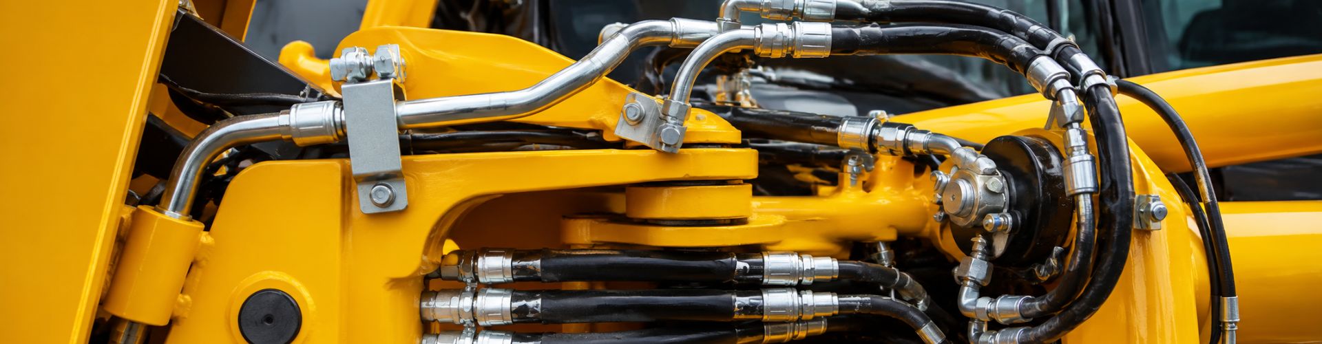
Troubleshooting Fluid Leaks Key Steps for Reliable Systems

Troubleshooting Fluid Leaks: Key Steps for Reliable Systems

Troubleshooting Fluid Leaks: Key Steps for Reliable Systems

Table of Contents

Introduction

Maintaining reliable fluid systems is crucial for ensuring operational efficiency, safety, and cost-effectiveness in industrial settings. Fluid leaks can lead to significant downtime, safety hazards, and increased operational costs. This article provides a comprehensive overview of fluid leaks in industrial systems, detailing their causes and impacts. The purpose is to equip you with the essential steps and knowledge needed to identify, troubleshoot, and resolve fluid leaks, thereby ensuring the reliability and longevity of your fluid systems.

Understanding Fluid Leaks

Fluid leaks refer to the unintended escape of liquids or gases from their intended containment systems. These leaks can occur in various systems such as hydraulic, pneumatic, fuel, and cooling systems, each with unique characteristics and challenges. Hydraulic systems, for instance, operate under high pressure and are prone to leaks in hoses, seals, and hydraulic fittings due to the intense pressure. Pneumatic systems, using compressed air, can experience leaks at connections and joints, leading to energy loss and inefficiency.

Common Causes

Brake Line Fitting leak

Wear and Tear:

Over time, the components of any fluid system are subject to natural degradation. Seals, gaskets, hoses, and fittings can wear out due to constant use, exposure to harsh environmental conditions, and the pressure of fluid passing through them. As these parts wear down, they become less effective at containing fluids, leading to leaks. Regular inspection and maintenance are essential to detect and replace worn components before they cause significant issues.

Improper Installation:

Incorrect assembly or installation of system components can result in immediate or eventual leaks. This can include improperly tightened fittings, misaligned seals, or using incompatible materials. For instance, over-tightening can damage threads and seals, while under-tightening can leave gaps for fluid to escape. Ensuring that installation is performed by trained professionals and according to manufacturer specifications is crucial to prevent leaks from the start.

Material Defects:

Even with proper installation and maintenance, material defects can lead to leaks. Defects in manufacturing, such as cracks, porosity, or weak spots in the material, can compromise the integrity of the system. These defects may not be immediately apparent but can become critical under operational stress. Quality control during manufacturing and thorough inspection before installation can help identify and mitigate the risk of material defects.

Impact of Leaks

System Performance:

Fluid leaks can significantly reduce the efficiency and performance of a system. In hydraulic systems, leaks lead to a loss of hydraulic fluid, which reduces the system’s ability to generate the necessary force. This can result in slower operation, diminished power, and potential failure to perform critical tasks. In pneumatic systems, air leaks cause a pressure drop, leading to inefficient operation and increased energy consumption.

Safety:

Leaks pose a considerable safety risk in industrial environments. Hydraulic fluids can be flammable, posing a fire hazard if they come into contact with hot surfaces or sparks. Additionally, leaked fluids can create slippery surfaces, increasing the risk of slips and falls. In pneumatic systems, leaks can lead to sudden bursts of compressed air, which can be dangerous to nearby personnel. Ensuring that leaks are promptly addressed is essential for maintaining a safe working environment.

Costs:

The financial impact of fluid leaks can be substantial. Direct costs include the expense of repairing or replacing damaged components and the cost of lost fluids. Indirect costs can be even more significant, including downtime due to system failures, increased energy consumption, and potential damage to other system parts.

Identifying Fluid Leaks

Visual Inspection

Visual inspection is often the first step in identifying fluid leaks. This technique involves a thorough examination of the system for any visible signs of leakage. Here are some detailed methods used in visual inspection:

Checking for Puddles, Stains, and Wet Spots:

Puddles: Look for puddles of fluid underneath equipment, pipes, or connections. These can indicate a significant leak that needs immediate attention.

Stains: Examine surfaces around the system for stains, which can indicate a slow or intermittent leak. Dried fluid can leave behind discoloration or residue.

Wet Spots: Feel for wet spots on components such as hoses, fittings, and seals. Even small wet areas can signify a leak, especially in high-pressure systems.

Additional Techniques:

Using Flashlights: Utilize a strong flashlight to enhance visibility in dark or hard-to-reach areas.

Inspection Mirrors: Employ mirrors to inspect the backside of components or areas that are not easily visible.

Clean Surfaces: Regularly clean surfaces to make new leaks easier to detect.

Pressure Testing

Pressure testing is a reliable method to detect leaks by observing pressure drops in sealed systems. This technique involves the following steps:

Preparation:

Seal the System: Ensure the system is properly sealed and all outlets are closed.

Introduce Pressure: Apply a controlled pressure to the system using a pump or compressor.

Monitoring:

Pressure Gauges: Use pressure gauges to monitor the system. A drop in pressure over time indicates a leak.

Time-Based Observation: Allow the system to remain under pressure for a specified period and observe any changes in pressure readings.

Advanced Techniques:

Hydrostatic Testing: Use water as the test medium, especially for systems that handle non-compressible fluids. This method minimizes the risk of explosive failure.

Pneumatic Testing: Use air or gas for systems that operate under high pressure or handle gases. Extra caution is necessary due to the compressible nature of gases.

Ultrasonic Detection

Ultrasonic detection involves using specialized equipment to detect sound waves produced by fluid escaping through small leaks. Here’s how it works:

Equipment:

Ultrasonic Detectors: Devices equipped with sensitive microphones and amplifiers to pick up high-frequency sounds.

Headsets: Operators wear headsets to hear the amplified ultrasonic signals.

Procedure:

Scan the System: Move the ultrasonic detector along the system components, focusing on joints, fittings, and seals.

Listen for Signals: Identify the characteristic hissing or whooshing sounds that indicate a leak.

Pinpointing Leaks: Use the detector to narrow down the exact location of the leak by following the sound intensity.

Advantages:

Non-Intrusive: No need to disassemble components, allowing for quick and efficient inspections.

Sensitivity: Capable of detecting very small leaks that may not be visible or detectable by other means.

AN Fitting Leaking check

Other Diagnostic Tools

Dye Testing:

Introduction of Tracer Dye: Add a fluorescent or colored dye to the system fluid.

Visual Inspection: Use ultraviolet light (for fluorescent dyes) or look for visible color changes to spot the dye escaping from leaks.

Advantages: Provides a clear visual indication of leak locations, even in complex systems.

Sniffer Dogs:

Training: Dogs are specially trained to detect specific fluids by scent.

Application: Useful in large or complex installations where traditional methods are impractical.

Efficiency: Dogs can quickly cover large areas and pinpoint leaks with high accuracy.

Electronic Leak Detectors:

Sensors: Equipped with sensors that detect specific gases or fluids.

Procedure: Move the detector along the system components. The device will alert the operator (usually with a visual or audible signal) when it detects a leak.

Advantages: Highly sensitive and can detect leaks that are difficult to identify visually or by other means.

Common Leak Points and Their Causes

Connections and Fittings

Connections and fittings are critical points in any fluid system, and they are often susceptible to leaks due to various factors.

Worn Seals:

Description: Seals are designed to prevent fluid from escaping at connection points. Over time, these seals can wear out due to constant pressure, temperature fluctuations, and chemical exposure.

Causes: High operational temperatures, frequent pressure changes, and exposure to aggressive chemicals can accelerate the wear of seals, leading to cracks, hardening, or loss of elasticity.

Prevention: Regular inspection and timely replacement of seals, using seals made from materials compatible with the operating environment.

Damaged O-Rings:

Description: O-rings are commonly used to seal connections and prevent leaks. Damage to O-rings can cause significant leakage.

Causes: Improper installation, such as twisting or pinching during assembly, and exposure to incompatible fluids or excessive temperatures can damage O-rings.

Prevention: Ensuring proper installation techniques, selecting the right material for O-rings based on the fluid and temperature conditions, and replacing O-rings regularly as part of maintenance.

Thread Issues:

Description: Threads on fittings and connectors ensure a tight, leak-proof connection. Issues with threads can lead to leaks.

Causes: Cross-threading, over-tightening, or wear and tear can damage threads, preventing proper sealing.

Prevention: Training personnel on proper threading techniques, using thread sealants or tapes where appropriate, and replacing worn or damaged threaded components.

Hoses and Tubing

Hoses and tubing are essential for transporting fluids within a system, but they are vulnerable to various issues that can lead to leaks.

Abrasion:

Description: Hoses and tubing can suffer from abrasion when they rub against other surfaces or components.

Causes: Improper routing, lack of protective coverings, or constant movement can cause abrasion, leading to wear and eventual leaks.

Prevention: Properly routing hoses to avoid contact with abrasive surfaces, using protective sleeves or guards, and regularly inspecting hoses for signs of wear.

Wear:

Description: Over time, hoses and tubing naturally degrade and wear out.

Causes: Continuous flexing, exposure to harsh environmental conditions, and high-pressure operation can contribute to wear.

Prevention: Implementing a maintenance schedule that includes regular inspection and replacement of worn hoses and tubing, and using high-quality materials designed for specific operational conditions.

Improper Routing:

Description: Incorrectly routed hoses and tubing can be subjected to unnecessary stress and strain.

Causes: Bending hoses too sharply, stretching them too tightly, or routing them near sharp edges can create stress points that lead to leaks.

Prevention: Following manufacturer guidelines for routing, avoiding tight bends and excessive stretching, and using proper supports and clamps to secure hoses in place.

Troubleshooting Fluid Leaks

Valves and Pumps

Valves and pumps are integral components of fluid systems, and they can be common points of failure leading to leaks.

Internal Failures:

Description: Internal components of valves and pumps, such as seals, gaskets, and moving parts, can wear out or fail.

Causes: Prolonged use, exposure to abrasive or corrosive fluids, and inadequate lubrication can cause internal components to deteriorate.

Prevention: Regular maintenance, including lubrication, inspection, and replacement of worn parts, using materials compatible with the operating environment, and ensuring proper installation and operation.

Worn-Out Seals:

Description: Seals within valves and pumps prevent fluid from leaking out of the internal components.

Causes: Continuous operation under high pressure and temperature conditions, and exposure to aggressive fluids can wear out seals.

Prevention: Periodic inspection and replacement of seals, using seals designed for specific operational conditions, and maintaining proper operational parameters.

Damaged Components:

Description: Components such as valve seats, pump impellers, and diaphragms can get damaged, leading to leaks.

Causes: Abrasive particles in the fluid, cavitation, and mechanical damage during maintenance can harm these components.

Prevention: Installing filters to remove particulates, monitoring for signs of cavitation, and handling components carefully during maintenance.

Flanges and Joints

Flanges and joints are points where sections of piping or equipment are joined together, and they are prone to leaks if not properly maintained.

Poor Sealing Surfaces:

Description: The surfaces of flanges and joints must be smooth and properly aligned to ensure a tight seal.

Causes: Corrosion, erosion, or damage during installation can compromise the sealing surface.

Prevention: Regular inspection and maintenance of sealing surfaces, using appropriate gaskets and sealants, and ensuring proper alignment during installation.

Improper Torque:

Description: The bolts securing flanges and joints must be tightened to the correct torque to ensure a leak-proof seal.

Causes: Under-tightening can leave gaps while over-tightening can crush gaskets and deform sealing surfaces.

Prevention: Using a calibrated torque wrench to ensure bolts are tightened to the manufacturer’s specifications, and following proper tightening sequences.

Gasket Failures:

Description: Gaskets are used to seal flanges and joints, and their failure can lead to leaks.

Causes: Improper installation, using incorrect gasket materials, and exposure to extreme temperatures and pressures can cause gasket failure.

Prevention: Selecting the right gasket material for the application, ensuring proper installation procedures, and replacing gaskets regularly as part of preventive maintenance.

Troubleshooting Techniques

Step-by-Step Guide

Effective troubleshooting of fluid leaks involves a systematic approach to identify, verify, and rectify the issue. The following step-by-step guide outlines the essential procedures:

Isolate the Affected Area:

Identify the Section: Carefully analyze the system to locate the general area where the leak is occurring. This can involve following the fluid path and checking for areas with visible signs of leakage such as puddles, stains, or moisture.

Shut Down the System: If safe to do so, shut down the affected section of the system to prevent further leakage and to allow for a safer inspection environment.

Verify the Leak Source:

Pinpoint the Exact Origin: Use diagnostic tools such as pressure testing, ultrasonic detectors, or dye testing to confirm the exact source of the leak. It’s essential to distinguish between the actual leak point and areas where fluid may have accumulated due to gravity or system pressure.

Double-Check for Multiple Leaks: Sometimes, there may be more than one leak in a system. Ensure a thorough check to identify all potential leak points.

Inspect for Damage or Wear:

Examine Components: Carefully inspect the components around the identified leak point for signs of damage or wear. This includes checking seals, O-rings, fittings, hoses, and connections for cracks, abrasions, or other forms of degradation.

Assess Condition: Evaluate the overall condition of the affected components. Even if the damage is minor, consider whether it’s part of a broader issue that could lead to future leaks.

Test and Retest After Repairs:

Conduct Initial Tests: After performing repairs, such as replacing seals or tightening connections, conduct an initial test to ensure the leak has been addressed. This could involve re-pressurizing the system or using detection tools to confirm the absence of leaks.

Monitor Over Time: Even after initial tests, continue to monitor the repaired area over time to ensure the fix is durable and that no new leaks emerge.

Common Fixes

Addressing the root causes of leaks often involves specific repair techniques. Here are some of the most common fixes for typical leak sources:

Tightening Connections:

Ensuring Proper Security: Loose fittings and connections are a common cause of leaks. Use appropriate tools to tighten connections, ensuring they are secure but not over-tightened, which can damage threads and seals.

Using Torque Specifications: Follow the manufacturer’s torque specifications to ensure connections are tightened to the correct degree. This prevents under-tightening (which can cause leaks) and over-tightening (which can damage components).

Replacing Seals:

Installing New O-rings or Seals: Damaged or worn seals are frequent culprits of leaks. Replace old seals with new ones that are compatible with the system’s fluid and operating conditions.

Proper Installation: Ensure seals are installed correctly, avoiding pinching, twisting, or improper seating, which can lead to immediate or future leaks.

Re-Routing Hoses:

Adjusting Hose Paths: Incorrect hose routing can cause excessive stress and wear. Re-route hoses to eliminate sharp bends, kinks, or contact with abrasive surfaces.

Using Supports and Clamps: Properly secure hoses with supports and clamps to maintain optimal routing and minimize movement and vibration.

Advanced Troubleshooting Tips

Using Advanced Diagnostic Tools:

Thermal Imaging: Employ thermal imaging cameras to detect temperature anomalies that may indicate fluid leaks.

Acoustic Emission Testing: Utilize acoustic emission sensors to detect high-frequency sounds produced by fluid escaping under pressure.

Implementing a Preventative Maintenance Plan:

Scheduled Inspections: Conduct regular system inspections and maintenance to identify and address potential issues before they become significant problems.

Component Replacement: Replace high-risk components based on a predefined schedule, even if they have not yet failed, to prevent unexpected leaks.

Documenting Repairs and Maintenance:

Maintaining Records: Keep detailed records of all inspections, repairs, and maintenance activities. This helps in tracking the history of leaks and understanding patterns or recurring issues.

Conclusion

Understanding fluid leaks, identifying common leak points, employing effective troubleshooting techniques, and adopting preventative measures are critical steps in maintaining reliable fluid systems. Innovations in leak detection and prevention technologies will continue to evolve, enhancing system reliability. A proactive approach, encompassing regular maintenance and adherence to best practices, is essential for preventing leaks and ensuring the longevity and efficiency of fluid systems.

FAQ

The most common causes include wear and tear of seals and O-rings, improper installation of components, material defects, and damage to hoses or fittings due to abrasion or improper routing.

Perform a visual inspection to look for puddles, stains, or wet spots around components. Use pressure testing, ultrasonic detectors, or dye testing for more precise identification of leaks.

First, isolate the affected area to prevent further leakage. Verify the exact source of the leak, inspect for damage or wear, and perform necessary repairs such as tightening connections or replacing seals. Test and retest the system to ensure the leak is fixed.

Regular inspections should be part of your preventative maintenance plan. Depending on the system’s usage and operating conditions, inspections can range from daily checks to monthly thorough inspections.

Useful tools include pressure gauges for pressure testing, ultrasonic detectors for identifying high-frequency sound waves, dye testing kits, and electronic leak detectors. Visual inspection aids like flashlights and inspection mirrors are also essential.

Implement a regular maintenance schedule, use high-quality components, ensure proper installation practices, and train personnel on leak prevention techniques. Regularly inspect and replace worn components to avoid unexpected failures.

Proper Assembly of Parallel Thread Adjustable Fittings

Proper Assembly of Parallel Thread Adjustable Fittings

Proper Assembly of Parallel Thread Adjustable Fittings

Table of Contents

Introduction

Parallel thread fittings are essential components in various industrial applications, providing secure connections between hydraulic systems, pipelines, and machinery. These fittings feature parallel threads, which differ from tapered threads by maintaining a consistent diameter along their length, ensuring a tight seal with the help of a sealing washer or O-ring. This guide aims to provide a comprehensive overview of the correct assembly procedures for parallel thread fittings.

Understanding Parallel Thread Fittings

Components and Their Functions

Body:

The body of a parallel thread adjustable fitting is the primary component that connects with other parts of the system. It serves as the structural foundation, housing the threads and adjustment mechanism. The body ensures that the fitting maintains its integrity and provides a stable connection point for the other elements of the system.

Adjustment Mechanism:

The adjustment mechanism within these fittings is crucial for achieving precise alignment and secure connections. This mechanism typically includes a locknut or a similar device, which helps maintain the set position once the fitting is adjusted. The adjustment mechanism allows for fine-tuning, ensuring that the fitting can be positioned accurately within the system.

Threads:

The threads on these fittings are parallel, meaning they maintain a consistent diameter along their length. Unlike tapered threads, parallel threads do not taper but instead rely on a sealing washer or O-ring to achieve a leak-free connection. Key specifications of threads include the thread size, pitch, and profile, which must be compatible with corresponding components to ensure a proper fit and seal.

parallel thread adjustable Fitting

Applications and Benefits

Parallel thread fittings are utilized across a broad spectrum of industries due to their versatility and reliability. Common applications include manufacturing, automotive, aerospace, and various hydraulic and pneumatic systems. These fittings are chosen for their ability to provide secure, leak-free connections, even in high-pressure environments.

Easy Adjustability:

One of the primary benefits of parallel thread fittings is their easy adjustability. The adjustment mechanism allows for precise alignment, making installation and maintenance straightforward. This feature is particularly valuable in complex systems where exact positioning is essential for optimal performance.

Reliable Sealing:

The design of parallel thread fittings ensures a reliable seal, reducing the risk of leaks. This is achieved through the use of sealing washers or O-rings, which compensate for the lack of taper in the threads. The result is a robust, leak-free connection that can withstand varying operational conditions.

Compatibility with High-Pressure Systems:

These fittings are engineered to perform under high-pressure conditions, making them suitable for demanding applications. Their robust construction and reliable sealing capabilities ensure that they can handle the stresses associated with high-pressure environments without compromising performance.

Types of Parallel Threads

BSPP (British Standard Pipe Parallel)

BSPP threads are one of the most common types of parallel threads used globally, especially in Europe. These threads are characterized by a uniform diameter along their length and a 55-degree thread angle. BSPP threads rely on a bonded seal or an O-ring in a groove to create a leak-tight connection, making them suitable for applications where reliable sealing is crucial, such as hydraulic and pneumatic systems.

UNF (Unified National Fine)

UNF threads are widely used in North America and are part of the Unified Thread Standard. They have a finer pitch compared to UNC (Unified National Coarse) threads, allowing for a greater number of threads per inch. This fine threading provides a stronger and more secure connection, ideal for applications requiring high precision and where space constraints demand a tighter thread fit, such as in automotive and aerospace industries.

ISO Parallel Threads (Metric)

ISO parallel threads, also known as ISO 228-1 or G threads, follow the metric standard and are commonly used worldwide. These threads have a 60-degree thread angle and a consistent diameter, which makes them suitable for a wide range of applications. ISO parallel threads are often found in European and Asian machinery and are preferred for their international standardization, ensuring compatibility across different equipment and components.

Metric standard threads fitting Chart Topa

NPS (National Pipe Straight)

NPS threads are used primarily in the United States and Canada and are similar in design to NPT (National Pipe Tapered) threads but maintain a constant diameter along their length. They are often used in low-pressure applications where the primary sealing method is a gasket or an O-ring rather than the threads themselves. NPS threads are common in plumbing and piping systems where precise alignment is required without the need for thread interference.

SAE Straight Thread

SAE straight threads are designed to provide a reliable, reusable connection in hydraulic and other fluid power systems. These threads are specified by the Society of Automotive Engineers (SAE) and are often used in conjunction with O-rings or other seals to ensure a leak-free connection. The threads themselves provide the mechanical hold, while the seal ensures the system’s integrity under high pressure. This combination is widely used in automotive and industrial applications for its robustness and reliability.

Step-by-Step Assembly Process

Inspection of Components

Checking for Cleanliness:

Before beginning the assembly process, it is crucial to ensure all components are free from dirt, debris, and contaminants. Contaminants can compromise the seal and connection, leading to potential leaks and system failures. Use a clean, lint-free cloth to wipe down each part. For more stubborn debris, consider using a mild solvent that is compatible with the materials of the fittings. Ensuring cleanliness helps maintain the integrity of the assembly and prevents premature wear.

Inspecting Threads for Damage or Wear:

Carefully examine the threads on all components for any signs of wear, deformation, or damage. Even minor imperfections can hinder proper assembly and lead to issues such as cross-threading or inadequate sealing. Use a magnifying glass if necessary to get a detailed view of the thread condition. If you find any damage, replace the affected parts to ensure the assembly process proceeds smoothly and securely.

Aligning the Threads

Importance of Alignment:

Proper thread alignment is essential to prevent cross-threading, which can damage the threads and compromise the seal. Cross-threading occurs when threads are misaligned, causing them to cut across each other rather than mesh smoothly. This not only damages the threads but also affects the fitting’s ability to seal properly.

Techniques for Preventing Cross-threading:

Start threading by hand: Begin the threading process manually to ensure the threads engage smoothly. Hand-threading allows you to feel for any resistance, which could indicate misalignment.

Use light pressure: Apply gentle pressure to guide the threads into place. If you encounter resistance, stop and realign the threads before continuing.

install ferrule fitting

Tightening Components

Recommended Torque Specifications:

Refer to the manufacturer’s guidelines for specific torque values for your fittings. Using the correct torque ensures a secure fit without over-tightening, which can strip the threads or damage the fitting.

Techniques for Even Tightening:

Apply torque evenly: Distribute the torque evenly across the fitting, using a crisscross pattern if applicable. This helps to prevent uneven stress on the fitting and ensures a secure connection.

Avoid sudden or excessive force: Gradual and steady pressure should be used when tightening. Sudden force can lead to over-tightening or damage to the threads.

Ensuring Proper Sealing

Use of Thread Sealants:

Applying a thread sealant, such as PTFE tape or liquid sealant, is essential for ensuring a leak-free connection. Wrap PTFE tape around the male threads, ensuring even coverage without excess. For liquid sealants, apply a thin, uniform layer to the threads. Sealants fill the gaps between threads, enhancing the seal and preventing leaks.

Checking for Leaks and Verifying the Seal:

Pressurize the system: After assembly, gradually pressurize the system to its operating pressure.

Inspect for leaks: Use soapy water or a leak detection fluid on the connections and watch for bubbles, which indicate leaks. Address any leaks by disassembling and reassembling the fitting with additional sealant if necessary.

Verification and Final Checks

Steps to Ensure the Assembly Is Complete and Correct:

Double-check all connections and fittings: Ensure all parts are properly tightened and aligned.

Confirm proper torque and alignment: Verify that all connections meet the recommended torque specifications and that the threads are correctly aligned.

Tips for Testing the Assembled Fitting:

Conduct a pressure test: Perform a pressure test to ensure the integrity of the seal. This involves pressurizing the system and monitoring for any signs of leakage.

Monitor for signs of leakage or pressure drop: Keep an eye on the system over time to detect any gradual leaks or pressure drops, which could indicate an issue with the assembly.

Common Issues and Troubleshooting

Cross-threading

Cross-threading occurs when the threads on the fittings are misaligned during assembly. This misalignment causes the threads to cut across each other rather than engage smoothly, leading to damage to both the male and female threads. Cross-threading not only makes it difficult to achieve a secure connection but can also result in leaks and compromised system integrity. This issue often arises when excessive force is applied during the initial threading, or when the threads are not started correctly by hand.

Inadequate Sealing

Inadequate sealing is another common problem in the assembly of parallel thread fittings. This issue often stems from insufficient application of thread sealant, incorrect torque application, or using the wrong type of sealant for the specific threads and operating conditions. Inadequate sealing can lead to leaks, which compromise the efficiency and safety of the system. It’s crucial to ensure that the sealant is applied correctly and that the fittings are tightened to the manufacturer’s specified torque values to achieve a proper seal.

Troubleshooting Tips

Identifying and Addressing Common Issues

For Cross-threading:

Disassemble and Inspect Threads: If cross-threading is suspected, immediately stop the assembly process and disassemble the connection. Carefully inspect both the male and female threads for any signs of damage or wear.

Realign Carefully: Clean the threads and realign them carefully. Start the threading process by hand to ensure the threads engage smoothly. If the threads are significantly damaged, consider replacing the affected components to avoid future issues.

For Sealing Issues:

Reapply Thread Sealant: If you encounter sealing issues, disassemble the fitting and remove any old sealant. Clean the threads thoroughly and reapply the appropriate thread sealant. Ensure an even and sufficient application, covering all thread surfaces that will engage.

Ensure Proper Torque: Use a torque wrench to tighten the fittings to the manufacturer’s specified torque values. This ensures a secure fit and proper sealing without over-tightening, which could damage the threads or the seal.

Solutions for Common Problems

Use Thread Gauges to Verify Thread Integrity:

Thread Gauges: Thread gauges are essential tools for verifying the integrity and compatibility of threads. Use them to check the pitch, diameter, and profile of the threads before assembly. This helps ensure that the threads are in good condition and compatible, preventing cross-threading and sealing issues.

Routine Inspections: Regularly inspect and verify thread integrity using thread gauges, especially if fittings are reused or have been stored for an extended period.

Replace Damaged Components as Necessary:

Identifying Damage: If you identify any damage to the threads or fittings during inspection, replace the damaged components immediately. Using compromised parts can lead to repeated assembly issues and potential system failures.

Quality Assurance: Ensure that replacement components meet the required specifications and quality standards. Using high-quality parts reduces the risk of future problems and enhances the overall reliability of the system.

By addressing common issues such as cross-threading and inadequate sealing through careful inspection, proper technique, and the use of appropriate tools and sealants, you can ensure reliable, leak-free connections in your parallel thread adjustable fittings. Consistent attention to detail and adherence to best practices will help maintain the integrity and efficiency of your hydraulic or pneumatic systems.

Conclusion

Proper assembly of parallel thread fittings is critical for system performance and longevity. Key steps include thorough inspection, correct alignment, proper tightening, and effective sealing. By following the outlined procedures and maintaining regular inspections, you can ensure the reliability and efficiency of your fittings, preventing costly downtime and repairs. Follow this guide to achieve optimal results with your parallel thread fittings. Share this post with your peers and explore additional resources or contact us for further assistance.

FAQ

Parallel thread fittings are connectors used in hydraulic and pneumatic systems to join different components. They feature parallel threads, which maintain a consistent diameter and typically use a sealing washer or O-ring to ensure a leak-proof connection.

To prevent cross-threading, always start threading the components by hand to ensure smooth engagement. Use light pressure to guide the threads into place and avoid using excessive force, which can cause misalignment and damage.

The choice of thread sealant depends on the specific application and the type of fluid being used in the system. PTFE tape and liquid thread sealants are common options. Ensure you use a sealant that is compatible with your system’s materials and operating conditions.

After assembly, pressurize the system to its operating pressure and inspect the connections using soapy water or a leak detection fluid. Look for bubbles forming around the fittings, which indicate leaks. Address any leaks by reassembling the fittings with additional sealant if necessary.

Common tools needed for assembly include adjustable wrenches, thread sealant (PTFE tape or liquid), a torque wrench for precise tightening, and inspection tools such as a magnifying glass and thread gauges to check for thread integrity.

Replace your fittings if you notice signs of wear, damage, or deformation during routine inspections. Regularly check for leaks, corrosion, and thread wear. If the fittings are damaged or no longer provide a reliable seal, replace them with new, compatible components to maintain system integrity.

Proper Assembly of 37° Flare Fittings Using the Flats Method

Proper Assembly of 37° Flare Fittings Using the Flats Method

Proper Assembly of 37° Flare Fittings Using the Flats Method

Introduction

37° flare fittings are crucial components in hydraulic systems, known for their high-pressure tolerance, leak resistance, and reusability. These fittings connect tubes and hoses, ensuring fluid integrity and system reliability. Proper assembly of these fittings is essential to prevent leaks and maintain system performance. The Flats Method is a precise technique used to achieve the correct torque when assembling 37° flare cone fittings. By tightening the fitting to a specific number of flats, this method ensures consistent and reliable connections.

Understanding 37° Flare Cone Fittings

37° fittings, also known as JIC (Joint Industry Council) fittings, are a type of compression fitting used in high-pressure hydraulic systems. These fittings consist of a nut, a sleeve (or ferrule), and a body. The tube end is flared to a 37° angle, which mates with the fitting’s conical seat, creating a tight seal. The main components include:

  • Nut: Tightens the connection.
  • Sleeve: Supports the tube and ensures alignment.
  • Body: Contains the 37° seat and threads.
An and JIC Fittings

Common Applications in Hydraulic Systems

37° flare cone fittings are widely used in various industries due to their robust design and high-pressure capability.

Common applications include:

  • Automotive: Brake lines and fuel systems.
  • Industrial Machinery: Hydraulic circuits in heavy equipment.
  • Marine: Hydraulic systems in ships and boats.
  • Agriculture: Machinery and equipment requiring durable hydraulic connections.

Advantages

37° flare cone fittings offer several benefits that make them a preferred choice in many hydraulic applications:

  • High-Pressure Tolerance: These fittings can handle high-pressure environments, making them ideal for demanding hydraulic systems. Their robust construction ensures that they can withstand the stress and pressure without failure.
  • Leak Resistance: The precise 37° flare angle provides a reliable seal, reducing the risk of leaks. This is crucial for maintaining system integrity and preventing fluid loss, which can lead to inefficiencies and potential hazards.
  • Reusability: 37° flare cone fittings are designed to be disassembled and reassembled multiple times without losing their sealing capability. This reusability makes them cost-effective and convenient for maintenance and repairs.

Flaring the Tube

Step-by-Step Guide to Flaring the Tube End

Cutting the Tube to the Desired Length

  • Measure and Mark: Begin by measuring the tube to the required length and marking it with a marker or scribe. Ensure accuracy to avoid cutting too short or too long.
  • Secure the Tube: Place the tube in a tube cutter, ensuring it is securely positioned. Tighten the cutter just enough to hold the tube without crushing it.
  • Rotate and Tighten: Rotate the cutter around the tube, gradually tightening the cutter with each rotation until the tube is cut through. Avoid over-tightening, as this can deform the tube.

Deburring the Inside and Outside of the Tube

  • Deburring Tool Selection: Choose an appropriate deburring tool designed for both the inside and outside of the tube.
  • Inside Deburring: Insert the deburring tool into the tube end and rotate it to remove any sharp edges or burrs. This step is crucial for preventing damage to the fitting during assembly.
  • Outside Deburring: Use the deburring tool on the outer edge of the tube to smooth out any rough spots. A clean, smooth edge ensures a better flare and seal.

Using the Flaring Tool to Create the Flare

  • Select the Flaring Tool: Choose a flaring tool compatible with the tube size and material. Ensure the tool is clean and in good condition.
  • Insert the Tube: Place the tube into the flaring tool’s clamp. The tube should extend slightly above the clamp to create the flare.
  • Tighten the Clamp: Secure the tube in place by tightening the clamp. Ensure the tube is centered and aligned correctly.
  • Create the Flare: Rotate the flaring tool’s handle to press the tube end into the flaring cone. Apply steady pressure to form a 37° flare.
  • Inspect the Flare: Remove the tube from the tool and inspect the flare. It should be even, smooth, and free of cracks or distortions.

Common Mistakes to Avoid During Flaring

  • Improper Tube Cutting: Cutting the tube unevenly can result in a poor flare and an unreliable connection. Always use a tube cutter for a clean cut.
  • Skipping Deburring: Failing to deburr the tube can cause damage to the fitting and compromise the seal. Always deburr both the inside and outside edges.
  • Incorrect Tool Selection: Using the wrong size or type of flaring tool can result in an improper flare. Ensure the tool matches the tube specifications.
  • Over-tightening the Clamp: Over-tightening can deform the tube while under-tightening can lead to slippage. Tighten the clamp just enough to hold the tube securely.
  • Inconsistent Pressure: Applying inconsistent pressure while flaring can lead to an uneven flare. Maintain steady, even pressure throughout the process.

Ensuring a Proper Flare for Optimal Connection

  • Even and Smooth Flare: A proper flare should be even and smooth, without any cracks, splits, or rough edges. This ensures a tight seal and reliable connection.
  • Correct Angle: The flare should be precisely at a 37° angle to match the fitting. Use a flaring tool designed for 37° flares to achieve this.
  • Clean Surface: Ensure the flared surface is clean and free of debris. Any dirt or particles can compromise the seal and lead to leaks.
  • Proper Alignment: When assembling the fitting, ensure the flare is properly aligned with the fitting’s nose. Misalignment can cause uneven pressure and potential leaks.
  • Tightening with Flats Method: Use the Flats Method to achieve the correct torque. This involves tightening the fitting to a specific number of flats (e.g., 1.5 or 2 flats) beyond hand-tightening to ensure a consistent and reliable connection.

The Flats Method Explained

Definition and Importance of the Flats Method

The Flats Method is a precise technique used to achieve the correct torque when assembling 37° flare cone fittings. By tightening the fitting by a specific number of flats beyond hand-tightening, this method ensures consistent and reliable connections. The flats refer to the flat sides of the hex nut on the fitting.

The importance of the Flats Method lies in its ability to provide a standardized approach to tightening, reducing the risk of under- or over-tightening. Proper torque is crucial in hydraulic systems to maintain leak-free connections and ensure the longevity of the fittings and tubes.

install 37° Flare Fitting

Step-by-Step Process for Using the Flats Method

Initial Hand-Tightening of Fittings

  • Position the Tube and Fitting: Align the flared tube end with the fitting nose. Ensure the flare seats are properly against the fitting’s conical surface.
  • Hand-Tighten the Nut: Begin by threading the nut onto the fitting body by hand. Turn the nut until it is snug and cannot be tightened further by hand. This ensures that the flare is properly seated and aligned.

Marking the Flats of the Fitting

  • Identify a Flat: Choose one of the flat sides of the hex nut as your starting point.
  • Mark the Flat: Use a permanent marker or scribe to mark this flat. This mark will serve as a reference point for the subsequent tightening process.

Tightening the Fitting by the Specified Number of Flats

  • Determine the Required Flats: Consult the manufacturer’s specifications to determine the correct number of flats to tighten beyond hand-tightening. This is typically expressed as a fraction or whole number (e.g., 1.5 flats or 2 flats).
  • Tighten Using a Wrench: Using a wrench, begin to tighten the nut. Count the flats as you turn the wrench, using your mark as a reference. For example, if the specification calls for 1.5 flats, you will turn the nut until your mark passes the 1.5 flat sides of the hex nut.
  • Ensure Consistent Pressure: Apply steady, consistent pressure while tightening to avoid any sudden movements that could result in uneven torque.

Benefits of Using the Flats Method Over Other Methods

  • Precision and Consistency: The Flats Method provides a precise and consistent way to achieve the correct torque, reducing variability that can occur with other methods.
  • Reduced Risk of Over-Tightening: Over-tightening can damage the fitting and tube, leading to potential leaks and failures. The Flats Method helps prevent this by providing a clear stopping point.
  • Ease of Use: The method is straightforward to implement, even for those new to assembling hydraulic fittings.
  • Reliability: By ensuring proper torque, the Flats Method enhances the reliability of the connection, contributing to the overall performance and safety of the hydraulic system.
  • Standardization: This method allows for standardization across different assemblies, making it easier to train personnel and maintain consistency in assembly processes.

Assembling the 37° Flare Cone Fittings

Positioning the Flare Against the Fitting Nose

  • Preparation: Begin by ensuring the tube is properly flared and deburred. The flare should be smooth and even, with no cracks or distortions.
  • Align the Tube: Position the flared tube end against the fitting nose. Make sure the flare sits perfectly on the conical seat of the fitting. This alignment is crucial for a proper seal.
  • Hold in Place: Hold the tube and fitting in place, ensuring they are aligned and the flare is seated correctly on the fitting nose.

Hand-Tightening the Fitting

  • Start Threading: Begin by threading the nut onto the fitting body by hand. This initial hand-tightening ensures that the threads engage correctly and the flare remains seated.
  • Snug Fit: Continue to turn the nut by hand until it is snug and cannot be tightened further without tools. This hand-tightening step is essential to maintain the alignment and ensure the flare is properly seated.
install ferrule fitting

Using the Flats Method to Achieve Proper Torque

  • Mark the Flats: Identify one of the flat sides of the hex nut and mark it with a permanent marker or scribe. This mark will help you track the number of flats turned during tightening.
  • Determine Flats to Tighten: Refer to the manufacturer’s specifications to determine the number of flats required for proper torque. This is usually indicated in the fitting’s assembly instructions.
  • Tighten the Nut: Using a wrench, begin to tighten the nut. Turn the nut by the specified number of flats (e.g., 1.5 flats or 2 flats) beyond the initial hand-tightened position. Use your mark as a reference point to ensure accuracy.
  • Apply Steady Pressure: Maintain steady, even pressure while turning the wrench to avoid any sudden movements that could cause uneven torque or damage the fitting.

Checking for Proper Alignment and Fit

  • Inspect the Connection: After tightening the nut using the Flats Method, inspect the connection to ensure the flare is properly seated and aligned with the fitting nose.
  • Check for Gaps: Look for any gaps between the flare and the fitting nose. There should be no visible gaps, as this could indicate misalignment or improper seating.
  • Verify Tightness: Ensure the nut is tightened to the specified torque by checking the number of flats turned. If necessary, adjust slightly to achieve the correct torque.

Tips for Ensuring a Leak-Free Connection

  • Proper Preparation: Always start with properly cut, deburred, and flared tubes. This preparation is critical for a good seal.
  • Use Quality Fittings: Ensure that you use high-quality fittings that match the specifications of your hydraulic system. Inferior fittings can lead to leaks and system failures.
  • Avoid Over-Tightening: Over-tightening can damage the fitting and the flare, leading to leaks. The Flats Method helps prevent this by providing a clear and standardized approach to tightening.
  • Regular Inspection: Periodically inspect the fittings for signs of wear, corrosion, or damage. Early detection of issues can prevent leaks and extend the life of your hydraulic system.
  • Consistent Maintenance: Follow a regular maintenance schedule to check the condition of all fittings and connections. This proactive approach ensures long-term reliability and performance.

Troubleshooting and Common Issues

Identifying and Fixing Leaks

  • Check for Fluid: Look for visible signs of fluid around the fitting. Leaks often present as wet spots or drips.
  • Tighten the Nut: If a leak is detected, attempt to tighten the fitting slightly more, following the Flats Method guidelines.
  • Replace Damaged Components: If tightening doesn’t resolve the leak, inspect the flare and fitting for damage and replace as necessary.

Inspecting the Flare and Fitting Surfaces

  • Visual Inspection: Examine the flare for cracks, irregularities, or deformation.
  • Surface Cleanliness: Ensure the fitting surfaces are clean and free of debris that could affect the seal.

Correcting Misalignment

  • Reposition the Tube: If the flare isn’t seated properly, loosen the fitting and reposition the tube to ensure proper alignment.
  • Re-tighten Carefully: Hand-tighten again, followed by the Flats Method to achieve the correct torque.

Addressing Under- or Over-Tightening

  • Under-Tightening: Identify by feeling a loose connection. Tighten the fitting to the correct specification using the Flats Method.
  • Over-Tightening: Look for signs such as distorted flares or cracked fittings. If over-tightened, replace the damaged components and reassemble correctly.

Preventing Damage to Fittings and Tubes

  • Use Proper Tools: Always use the right size wrench to avoid rounding off the nut or damaging the tube.
  • Follow Specifications: Adhere to manufacturer guidelines for torque and the number of flats to ensure consistent and damage-free assembly.
  • Regular Maintenance: Periodically inspect fittings for signs of wear or corrosion, replacing parts as needed to maintain system integrity.

Conclusion

Proper assembly of 37° flare fittings is crucial for ensuring leak-free and reliable hydraulic connections. By following the Flats Method, you achieve precise and consistent torque, which enhances the durability and performance of your system. This method standardizes the assembly process, reducing the risk of under- or over-tightening, and helps in maintaining optimal system integrity. We encourage you to adhere to the best practices outlined in this guide, including regular inspections and maintenance, to prolong the life of your fittings and tubes.

FAQ

37° flare cone fittings, also known as JIC fittings, are used in high-pressure hydraulic systems to connect tubes and hoses securely.

The Flats Method is a technique for tightening fittings by a specific number of flats beyond hand-tightening to ensure proper torque and a reliable seal.

Proper assembly prevents leaks, ensures system integrity, and extends the lifespan of hydraulic components.

Hand-tighten the fitting, mark one flat side, then tighten by the specified number of flats using a wrench.

Inspect the fitting and flare for damage, ensure proper alignment, and re-tighten or replace components as necessary.

Regular inspections should be conducted periodically to check for signs of wear, corrosion, or loosening to maintain system performance.

Preventing Leaks in Hydraulic Ports Expert Tips

Preventing Leaks in Hydraulic Ports: Expert Tips

Preventing Leaks in Hydraulic Ports: Expert Tips

Table of Contents

Introduction

Hydraulic systems are essential to many industries, from manufacturing and construction to automotive and aerospace. However, one of the most common and detrimental issues these systems face is leakage. Preventing leaks in ports is crucial for maintaining optimal system performance and ensuring safety. Hydraulic leaks can significantly degrade the efficiency of a system, leading to reduced power output, increased operational costs, and potential environmental hazards. Undetected leaks, in particular, can escalate into major failures, resulting in costly repairs and downtime. This article aims to provide a comprehensive guide on preventing leaks in ports by exploring various types, identifying common issues, and offering expert tips for effective leak prevention.

Understanding Hydraulic Ports

Ports are critical components in hydraulic systems, serving as connection points where hydraulic lines, fittings, and components join. Understanding the different types of ports and the common issues that can lead to leaks is essential for maintaining system integrity and performance.

Types of Ports

SAE J1926 Ports

SAE J1926 ports are a standard type of hydraulic port widely used in North America. These ports are designed with straight threads and an O-ring seal. The straight threads serve primarily to hold the fitting in place, while the O-ring provides the actual seal. This design allows for easy assembly and disassembly, making maintenance more straightforward.

ISO 6149 Ports

ISO 6149 ports are another common type of hydraulic port, primarily used in European applications. Like the SAE J1926, ISO 6149 ports also utilize straight threads and an O-ring seal. However, these ports are designed to meet international standards that may differ slightly from the SAE specifications. ISO 6149 ports are known for their precision and compatibility with global hydraulic systems, making them a preferred choice for multinational operations.

Differences and Similarities

While both SAE J1926 and ISO 6149 ports utilize straight threads and O-ring seals, there are key differences between the two. One primary difference lies in the dimensional standards and specifications. SAE J1926 ports adhere to the standards set by the Society of Automotive Engineers (SAE), whereas ISO 6149 ports follow the International Organization for Standardization (ISO) guidelines. These differences can affect the interchangeability of components and the specific applications for which each port type is best suited.

However, both port types share similarities in their fundamental design principles. The use of straight threads and O-ring seals in both types ensures a reliable and effective seal, minimizing the risk of leaks when properly assembled. Understanding these nuances helps in selecting the appropriate port type for a given application, ensuring compatibility and optimal performance.

Common Issues Leading to Leaks

Hydraulic port leaks can stem from various issues, often related to manufacturing, installation, and wear over time. Identifying and addressing these common issues is crucial for maintaining a leak-free system.

Manufacturing Defects

Manufacturing defects are a common cause of leaks in ports. These defects can include improperly machined threads, surface imperfections, and dimensional inaccuracies. Even minor defects can prevent the O-ring from seating correctly, leading to leaks. Quality control during the manufacturing process is essential to minimize the occurrence of such defects. Using components from reputable manufacturers who adhere to strict quality standards can help reduce the risk of leaks caused by manufacturing issues.

Leaks in Hydraulic Ports

Improper Installation

Improper installation is another significant contributor to hydraulic leaks. This can involve several factors, including incorrect torque application, misalignment of fittings, and failure to properly seat the O-ring. Over-tightening fittings can damage the threads and O-ring while under-tightening can result in insufficient sealing pressure. Proper training and adherence to installation guidelines are critical to ensure that fittings are installed correctly. Using the correct tools, such as calibrated torque wrenches, can also help achieve the proper installation and prevent leaks.

Wear and Tear Over Time

Wear and tear over time is an inevitable aspect of hydraulic systems. As components are subjected to constant pressure cycles, temperature fluctuations, and mechanical stress, they can degrade and wear out. O-rings can become brittle or damaged, threads can wear down, and seals can lose their effectiveness. Regular maintenance and inspection are essential to identify signs of wear and replace worn components before they lead to leaks. Implementing a proactive maintenance schedule can extend the lifespan of hydraulic systems and reduce the risk of unexpected leaks.

Understanding the types of ports and the common issues that can lead to leaks provides a solid foundation for maintaining a reliable hydraulic system. By addressing these factors through proper inspection, assembly, and maintenance practices, you can significantly reduce the risk of hydraulic leaks and ensure the long-term performance of your system.

Key Preventive Measures

Preventing leaks in ports requires a multifaceted approach that includes proper inspection techniques, correct assembly practices, and the selection of high-quality components. By focusing on these key preventive measures, you can enhance the reliability and efficiency of your hydraulic system.

Proper Inspection Techniques

Initial Inspection of Ports Before Use

Before incorporating any new port into your hydraulic system, it is essential to conduct a thorough initial inspection. This inspection should include checking for any visible defects, such as scratches, burrs, or other irregularities that could compromise the seal. Ensuring that the port is in perfect condition before use can prevent leaks from occurring right from the start.

Regular Maintenance Inspections

Regular maintenance inspections are crucial for identifying potential issues before they escalate into significant problems. These inspections should be scheduled at regular intervals, depending on the system’s usage and operating conditions. During maintenance checks, it is vital to inspect the condition of the ports, fittings, and seals to ensure they are still functioning correctly and have not developed any wear or damage.

Tools and Equipment for Effective Inspection

Using the right tools and equipment is essential for conducting effective inspections. Micrometers, calipers, and borescopes can help identify minute defects that might not be visible to the naked eye. Additionally, using dye penetrant or other non-destructive testing methods can reveal hidden cracks or imperfections. Investing in high-quality inspection tools can significantly improve the accuracy and effectiveness of your inspections.

Correct Assembly Practices

Importance of Torque Specifications

One of the most critical factors in preventing hydraulic leaks is adhering to the correct torque specifications during assembly. Over-tightening or under-tightening fittings can lead to improper sealing and eventual leaks. Always refer to the manufacturer’s torque specifications for each component and use a calibrated torque wrench to ensure accuracy.

Step-by-Step Guide to Assembling O-Ring Boss Fittings

Assembling O-ring boss fittings correctly is vital for achieving a leak-free seal. Begin by ensuring that the O-ring is in good condition and free from defects. Apply a suitable lubricant to the O-ring to reduce friction and prevent damage during assembly. Insert the fitting into the port, and hand-tighten it until the O-ring makes contact with the sealing surface. Use a torque wrench to tighten the fitting to the specified torque value, ensuring that it is neither too loose nor too tight.

Checking for Proper Seating and Alignment

Proper seating and alignment of fittings are crucial for preventing leaks. After tightening the fitting, check that it is correctly seated against the face of the port. There should be no gaps between the fitting and the port surface. Misalignment can cause uneven pressure on the seal, leading to leaks. If necessary, adjust the fitting to achieve proper alignment and seating.

Preventing Leaks in Hydraulic Port

Choosing the Right Components

Selecting High-Quality Fittings and O-rings

Choosing high-quality fittings and O-rings is essential for maintaining a leak-free hydraulic system. Look for components from reputable manufacturers that meet industry standards. High-quality fittings and O-rings are less likely to have manufacturing defects and are more durable, reducing the likelihood of leaks.

Compatibility Considerations Between Components

Compatibility between components is another critical factor in preventing leaks. Ensure that the fittings, ports, and O-rings are designed to work together. Mismatched components can lead to poor sealing and increased wear, resulting in leaks. Always verify compatibility before assembly.

Impact of Material Selection on Leak Prevention

The material selection of fittings and seals can significantly impact leak prevention. Materials should be chosen based on their compatibility with the hydraulic fluid, operating temperature, and pressure conditions. For example, certain elastomers used in O-rings may degrade when exposed to specific hydraulic fluids or high temperatures. Selecting materials that are resistant to these conditions will enhance the longevity and reliability of the seals, reducing the risk of leaks.

Detailed Troubleshooting Guide

Preventing leaks in ports requires a thorough troubleshooting process to identify and address potential issues. This detailed guide covers the essential steps for diagnosing and resolving leaks in hydraulic systems.

Initial Troubleshooting Steps

Depressurizing and Locking Out the System

Before beginning any troubleshooting, it is crucial to ensure the hydraulic system is depressurized and locked out. This step is vital for safety, preventing accidental fluid discharge or system activation during inspection and repair. Follow the manufacturer’s guidelines for safely depressurizing and locking out the system.

Visual Inspection for Obvious Signs of Damage

Once the system is safe to work on, perform a visual inspection of the ports and fittings. Look for obvious signs of damage such as cracks, dents, or corrosion. Inspect the O-rings for signs of wear, brittleness, or cuts. This initial inspection can help identify any glaring issues that might be causing leaks.

Inspecting Internal Threads

Checking for Damage or Wear in Female Ports

Internal threads, also known as female ports, are critical for creating a secure and leak-free connection. Check the threads for signs of damage or wear. Worn threads can prevent the fitting from seating properly, leading to leaks. Use a thread gauge to ensure the threads are within specification and have not been damaged by over-tightening or cross-threading.

Evaluating the O-Ring Sealing Surface

The O-ring sealing surface inside the port should be smooth and free of imperfections. This surface, typically counterbored or chamfered, must be inspected closely for scratches or other damage. Concentric scratches may not pose a problem, but perpendicular scratches can create leak paths by preventing the O-ring from forming a proper seal.

Identifying and Addressing Scratches and Sharp Edges

Sharp edges at the leading edge of the counterbore can damage the O-ring during installation. If sharp edges or significant scratches are found, they should be smoothed out using appropriate tools. Lubricating the O-ring and the sealing surface can also help prevent damage during assembly.

Assessing Assembly Quality

Verifying Torque and Proper Seating of Fittings

Proper torque application is essential to prevent leaks. Use a calibrated torque wrench to ensure that fittings are tightened to the manufacturer’s specifications. Over-tightening can damage threads and O-rings, while under-tightening can result in insufficient sealing pressure. After applying the correct torque, check that the fitting is seated properly against the face of the port. There should be no gaps between the fitting and the port surface.

Identifying Potential Assembly Errors

Common assembly errors that can lead to leaks include misalignment of fittings, incorrect O-ring placement, and failure to use the appropriate lubricant. During inspection, ensure that the fittings are aligned correctly and that the O-rings are seated properly in their grooves. Lubricants should be used where recommended to facilitate proper assembly and prevent O-ring damage.

Steps to Correct Improper Assembly

If improper assembly is identified, take the following steps to correct it:

Disassemble the Components: Carefully remove the fitting and inspect both the port and the fitting for damage.

Clean the Components: Ensure that all components are clean and free from debris that could interfere with sealing.

Reinstall the O-Ring: Place the O-ring in its groove, applying a suitable lubricant is recommended.

Align the Fitting: Align the fitting with the port, ensuring it is straight and not cross-threaded.

Apply Proper Torque: Use a calibrated torque wrench to tighten the fitting to the specified torque value.

Verify Seating: Check that the fitting is properly seated against the port with no gaps.

Common Problems and Solutions

Effectively preventing and troubleshooting leaks in ports involves understanding and addressing common problems. These problems can stem from manufacturing defects, assembly errors, and issues related to material and component selection. This section provides an overview of these common issues and offers practical solutions.

Manufacturing Defects

Recognizing Signs of Defective Ports

Manufacturing defects can manifest in various ways, including improper threading, surface imperfections, and dimensional inaccuracies. Signs of defective ports include:

Misaligned Threads: Threads that do not match the standard profile or are uneven.

Surface Imperfections: Scratches, burrs, or pits on the sealing surfaces.

Dimensional Errors: Ports that do not conform to specified dimensions, causing misfits with standard fittings.

To recognize these defects, use precise measuring tools such as thread gauges, micrometers, and borescopes. Visual inspection under adequate lighting is also crucial.

Handling Different Types of Fluids

How to Address and Rectify Manufacturing Issues

Addressing manufacturing defects involves several steps:

Quality Control: Implement rigorous quality control measures during manufacturing to catch defects early. This includes random sampling and detailed inspections.

Supplier Collaboration: Work closely with suppliers to ensure they understand the importance of quality standards and are committed to meeting them.

Component Replacement: If defects are identified, replace the defective ports with high-quality components from reliable suppliers.

Repair Techniques: Minor surface imperfections can sometimes be repaired using precision machining or polishing techniques.

Hydraulic Ports leak

Assembly Errors

Common Mistakes During Installation

Assembly errors are a leading cause of hydraulic port leaks. Common mistakes include:

Over-Tightening: Applying excessive torque can damage threads and O-rings.

Under-Tightening: Insufficient torque can result in inadequate sealing pressure.

Misalignment: Incorrect alignment of fittings can lead to improper seating and leaks.

Improper O-Ring Installation: Failing to properly seat the O-ring or using a damaged O-ring.

Tips for Avoiding These Errors

To avoid assembly errors:

Follow Manufacturer Guidelines: Always refer to the manufacturer’s torque specifications and installation procedures.

Use the Right Tools: Employ calibrated torque wrenches and alignment tools to ensure accurate assembly.

Training and Certification: Ensure that personnel are well-trained and, if possible, certified in hydraulic assembly practices.

Lubrication: Apply appropriate lubricants to O-rings and threads to facilitate proper installation and prevent damage.

Solutions for Correcting Improper Assembly

If improper assembly is detected, take the following corrective actions:

Disassemble and Inspect: Carefully disassemble the components and inspect for damage.

Replace Damaged Parts: If any parts are damaged, replace them with new ones.

Reassemble with Correct Torque: Reassemble the components using the correct torque and alignment procedures.

Check Sealing Surfaces: Ensure that all sealing surfaces are clean and free from defects before reassembly.

Material and Component Issues

Problems Arising from Incompatible Materials

Using incompatible materials can lead to several problems, including:

Chemical Incompatibility: Certain hydraulic fluids can react with O-ring materials, causing degradation.

Temperature Sensitivity: Materials that are not suitable for the operating temperature range can fail prematurely.

Mechanical Mismatch: Components made from incompatible materials can have differing expansion rates, leading to leaks under temperature fluctuations.

How to Select the Right Materials for Your System

Selecting the right materials involves:

Compatibility Checks: Ensure that all components are compatible with the hydraulic fluid and operating conditions.

Material Specifications: Refer to material specifications and industry standards to select appropriate materials for O-rings, seals, and fittings.

Consulting Experts: Seek advice from material science experts or hydraulic system specialists to make informed choices.

Conclusion

Throughout this guide, we have discussed various preventive measures such as meticulous initial inspections, regular maintenance checks, adherence to torque specifications, and selecting the right materials for your system. Continuous improvement and vigilance are crucial in maintaining a leak-free hydraulic system, as even minor oversights can lead to significant issues over time. As we wrap up, we encourage you to implement the tips and strategies discussed in this guide. By doing so, you can significantly reduce the risk of leaks and ensure the long-term performance of your hydraulic systems.

FAQ

The most common cause of hydraulic port leaks is improper assembly, such as incorrect torque application or misalignment of fittings.

Look for signs such as misaligned threads, surface imperfections, and dimensional inaccuracies. Using precise measuring tools and conducting a thorough visual inspection can help identify these defects.

If the scratch is perpendicular and deep, it can cause leaks. The best solution is to replace the port. For minor scratches, you might be able to smooth them out using precision tools.

Regular maintenance inspections should be conducted based on the system’s usage and operating conditions. Typically, a quarterly inspection is recommended for most hydraulic systems.

Choose O-ring materials compatible with your hydraulic fluid and operating temperature. Common materials include nitrile, fluorocarbon (Viton), and ethylene propylene (EPDM).

Using a torque wrench ensures that fittings are tightened to the manufacturer’s specified torque value, preventing over-tightening or under-tightening, which can lead to leaks.

Hydraulic Fittings Leaking Top Troubleshooting Tips to Know

Hydraulic Fittings Leaking? Top Troubleshooting Tips to Know

Hydraulic Fittings Leaking? Top Troubleshooting Tips to Know

Table of Contents

Introduction

Even the smallest leaks can lead to a significant reduction in system efficiency, potential safety hazards, and costly downtime. Hydraulic fluid leaks can also contribute to environmental contamination, further exacerbating the financial and operational impact. By understanding the root causes of hydraulic fitting leaks, recognizing early symptoms, and employing reliable troubleshooting techniques, operators can maintain system integrity, improve safety, and minimize the costs associated with leaks. This guide provides an in-depth look at these areas, offering practical solutions and preventative measures to ensure the longevity and reliability of hydraulic systems.

Understanding Hydraulic Fittings Leaking

Common Causes of Leaks

Improper Installation

Hydraulic fittings require precise installation techniques to ensure a proper seal and optimal performance. Improper installation is a prevalent cause of leaks, often resulting from incorrect fitting procedures. For instance, over-tightening fittings can damage the threads and deform the sealing surfaces, making it difficult for the fittings to create a secure seal. This deformation can lead to small gaps where hydraulic fluid can escape, resulting in leaks. On the other hand, under-tightening fittings can prevent a proper seal from forming in the first place, allowing fluid to leak out. Both over-tightening and under-tightening can compromise the integrity of the hydraulic system, highlighting the importance of following manufacturer specifications and using the correct torque settings during installation.

Compression Fitting Leaking rust

Damaged Components

Hydraulic systems rely on various components such as fittings, O-rings, and seals to maintain a leak-free environment. Over time, these components can suffer from wear and tear, cracks, or other forms of damage due to the high pressures and harsh operating conditions they are subjected to. Even minor imperfections, such as small cracks or abrasions, can compromise the seal, leading to fluid leaks. For example, a cracked O-ring or a damaged fitting thread can create pathways for fluid to escape, undermining the system’s efficiency. Proactively addressing wear and tear can prevent leaks and extend the lifespan of the hydraulic system.

Contamination

Dirt, debris, and other contaminants can infiltrate hydraulic systems, particularly during assembly or maintenance. These contaminants can obstruct the sealing surfaces or become embedded in the fittings, preventing proper sealing and resulting in leaks. For example, a small particle of dirt trapped between a fitting and its corresponding seal can create a tiny gap, allowing fluid to leak out. Contamination can also accelerate wear and tear on components, further increasing the risk of leaks. Maintaining cleanliness throughout the assembly and maintenance processes, and implementing contamination control practices, such as using clean tools and protective covers, are essential to preventing this common issue. Ensuring that all components are clean and free of contaminants can help maintain the integrity of the seals and prevent leaks.

Wear and Tear

Hydraulic systems are subject to high pressures and repetitive movements, which can cause gradual deterioration of components over time. Continuous exposure to extreme conditions can lead to the hardening, cracking, or wearing out of seals, and the loosening or corrosion of fittings. For example, seals may harden and lose their elasticity, preventing them from forming a tight seal, or fittings may corrode, creating rough surfaces that are prone to leaks. Regularly scheduled maintenance is necessary to mitigate the effects of wear and tear. This includes inspecting components for signs of deterioration and replacing worn parts before they fail. Timely replacement of worn components can prevent leaks, ensuring the hydraulic system remains efficient and reliable. By addressing wear and tear proactively, operators can avoid costly downtime and maintain optimal system performance.

Types of Leaks

External Leaks

External leaks are the most apparent and detectable type of hydraulic leaks, characterized by hydraulic fluid escaping from the system and becoming visible on the exterior. These leaks can often be identified by obvious signs such as pooling fluid beneath machinery, wet spots around fittings, or dripping fluid. The presence of external leaks is a clear indicator that the hydraulic system’s integrity has been compromised, and they require immediate attention. Left unaddressed, external leaks can lead to further system degradation, pose safety hazards, such as creating slippery surfaces that can cause accidents, and result in significant fluid loss. To mitigate these risks, it is crucial to conduct regular visual inspections of the hydraulic system, focusing on areas around fittings, joints, and connections where leaks are most likely to occur. Promptly addressing external leaks by tightening connections, replacing damaged components, or resealing joints can help maintain system performance and safety.

Internal Leaks

leaking hydraulic Fittings Topa

Internal leaks, while not visible externally, can have a profound impact on the performance of a hydraulic system. These leaks occur when hydraulic fluid bypasses internal seals or components within the system, resulting in fluid escaping from the designated flow paths. Unlike external leaks, internal leaks do not leave visible traces, making them more challenging to detect. However, they manifest through various symptoms such as decreased system pressure, slower operational speeds, and reduced overall efficiency. These symptoms occur because the leaked fluid cannot contribute to the system’s power output, leading to a loss of hydraulic power. Detecting internal leaks often requires specialized diagnostic tools and techniques. For example, pressure testing can help identify drops in pressure that indicate internal leaks, and flow meters can measure the rate of fluid movement to detect inconsistencies. Additionally, advanced methods such as thermal imaging can identify temperature changes associated with fluid bypassing within the system. Addressing internal leaks typically involves inspecting and replacing worn or damaged seals, ensuring proper alignment of components, and maintaining the cleanliness of the hydraulic fluid to prevent contamination-related leaks.

Symptoms of Hydraulic Fitting Leaks

Visible Fluid Drips

One of the most apparent and immediate signs of a hydraulic fitting leak is the presence of fluid drips or puddles under machinery or around fittings. These visible signs indicate that hydraulic fluid is escaping from the system, suggesting a breach in the fitting’s integrity. Such leaks can be identified by regular visual inspections of the equipment. Fluid accumulation on the floor or wet spots on and around hydraulic components are telltale indicators. Addressing these visible leaks promptly is crucial to prevent further fluid loss, which can lead to more extensive system damage, operational inefficiencies, and safety hazards. Ignoring visible fluid drips can also result in increased maintenance costs and potential environmental issues due to the spilled hydraulic fluid.

Decreased System Efficiency

Leaks in hydraulic systems often lead to a significant drop in system pressure, resulting in slower operation and reduced overall performance. When hydraulic machinery is not performing as expected—such as experiencing slower cycle times, reduced lifting capacity, or less responsive controls—it may indicate that fluid is leaking either internally or externally. This leakage prevents the system from maintaining the necessary pressure levels required for optimal operation. Operators should monitor the system’s performance indicators and pressure readings regularly. Any unexplained decrease in efficiency or performance should prompt an inspection for potential leaks. Identifying and repairing leaks early can restore system efficiency and prevent further degradation of hydraulic performance.

Noise and Vibration

Unusual noises, such as hissing, whistling, or increased vibration, can also be strong indicators of hydraulic leaks. These symptoms often suggest that air is entering the system or that hydraulic fluid is escaping under pressure. When air enters a hydraulic system, it can cause cavitation—creating pockets of air that collapse under pressure and produce loud, disruptive noises. Additionally, fluid escaping under pressure can create a whistling or hissing sound as it passes through small gaps or cracks in the fittings. Increased vibration can occur when the smooth operation of hydraulic components is disrupted by fluctuating pressure levels or fluid flow. Identifying and rectifying these noises and vibrations can help diagnose and fix leaks. Operators should listen for any changes in the usual sounds of their machinery and feel for unusual vibrations during operation.

Troubleshooting Tips

Initial Assessment

Visual Inspection: Begin by conducting a thorough visual inspection of the hydraulic system. Look for visible signs of fluid drips, pooling fluid, or wet areas around fittings, hoses, and other components. This can help quickly identify the presence of external leaks. Additionally, check for any obvious signs of damage, such as cracked or corroded fittings, which could be the source of the leak.

Identify the Type and Source of the Leak: Once a leak is detected, determine whether it is external or internal. External leaks are typically easier to spot due to visible fluid, while internal leaks may manifest through symptoms like decreased system performance or unusual noises. Identifying the exact location and nature of the leak is crucial for effective troubleshooting and repair.

Detailed Examination

Checking for Damaged Components: Inspect critical components such as O-rings, seals, and threads for signs of wear, cracks, or damage. Damaged O-rings or seals can fail to create a proper seal, leading to leaks. Similarly, worn or damaged threads on fittings can prevent secure connections, allowing fluid to escape.

Ensuring Proper Alignment and Fitment: Verify that all fittings are correctly aligned and securely fitted. Misalignment can cause improper sealing and result in leaks. Ensure that fittings are properly seated and that there are no gaps or misalignments that could compromise the seal.

Inspecting for Contamination and Cleanliness Issues: Ensure that all components are clean and free from debris. Contaminants such as dirt, dust, or metal particles can obstruct sealing surfaces or become embedded in fittings, leading to leaks. Maintaining a clean working environment and using clean tools and materials during assembly can help prevent contamination-related leaks.

Correct Installation Practices

Proper Torque Specifications: Follow the manufacturer’s guidelines for tightening fittings to the correct torque specifications. Over-tightening can damage threads and deform seals, while under-tightening can result in a loose connection that leaks. Using a calibrated torque wrench can help achieve the proper torque.

Using the Right Tools and Techniques: Employ appropriate tools and techniques to avoid damaging components during installation. For example, using the correct size wrenches and avoiding the use of excessive force can prevent damage to fittings and threads. Specialized tools designed for hydraulic systems can help ensure proper installation without causing damage.

Ensuring Alignment and Avoiding Over-Tightening: Properly align fittings during installation to ensure a secure and effective seal. Misalignment can lead to leaks, as mentioned earlier. Additionally, avoid over-tightening fittings, as this can damage the sealing surfaces and threads. Tighten fittings to the specified torque to achieve a balance between secure fitment and preventing damage.

Advanced Troubleshooting Techniques

Using Diagnostic Tools

Leak Detection Tools and Methods: To pinpoint leaks accurately, utilize specialized leak detection tools and methods. These can include ultrasonic leak detectors, which can identify high-frequency sounds generated by escaping fluid, and dye penetrant testing, where fluorescent dyes are added to the hydraulic fluid and visualized under UV light to detect leaks. These tools help identify even small or hidden leaks that might not be visible during a standard inspection.

Pressure Testing and Monitoring: Conduct pressure tests to identify and monitor potential leak points. Pressure testing involves applying a specific pressure to the hydraulic system and observing for any pressure drops, which indicate the presence of a leak. Monitoring system pressure over time can also help detect gradual leaks that may not be immediately apparent. Using pressure gauges and monitoring software can provide real-time data to help diagnose and locate leaks.

Addressing Specific Scenarios

SAE J1926 and ISO 6149 Ports: Follow specific guidelines for these common port types to prevent leaks. SAE J1926 and ISO 6149 ports have distinct sealing methods and installation requirements. Ensure that the correct O-rings, seals, and torque specifications are used according to the manufacturer’s guidelines. Properly aligning and seating the fittings in these ports is crucial to avoid leaks.

Manufacturer Recommendations: Adhere to manufacturer recommendations for installation and maintenance. Manufacturers provide specific instructions for the correct assembly, torque settings, and maintenance procedures for their components. Following these guidelines ensures that the components are installed and maintained according to best practices, reducing the risk of leaks.

Conclusion

Ensuring the integrity of hydraulic fittings is paramount to maintaining system efficiency and safety. Regular inspections help in the early detection of potential leaks, allowing for prompt intervention. Proper installation practices, including following torque specifications and using the right tools, prevent damage and ensure secure seals. High-quality components, free from defects and made to industry standards, are essential in preventing leaks. By addressing leaks promptly and maintaining a detailed maintenance log, operators can enhance system efficiency and safety, reducing downtime and operational costs.

FAQ

The most common causes include improper installation, damaged components, contamination, and wear and tear over time.

External leaks are usually visible as fluid drips, pooling under machinery, or wet spots around fittings.

Immediately inspect the area to determine the source of the leak, and address it by tightening fittings, replacing damaged components, or cleaning contaminants.

Hydraulic fittings should be inspected regularly as part of a routine maintenance schedule, typically every few months or as recommended by the manufacturer.

Specialized tools such as ultrasonic leak detectors, dye penetrant testing kits, and pressure gauges can help accurately detect leaks.

High-quality components are less likely to fail, reducing the risk of leaks, improving system reliability, and ensuring efficient operation.

How to Identify Hydraulic Fittings Orientation

How to Identify Hydraulic Fittings Orientation

How to Identify Hydraulic Fittings Orientation?

Table of Contents

Introduction

Improper orientation can lead to significant issues such as hose twisting, accelerated wear, and potential system malfunctions, which can be costly and dangerous. Hose twisting, for instance, can restrict fluid flow, increase pressure on the hose walls, and lead to premature wear or even catastrophic failure. These problems not only affect the hydraulic system’s performance but also pose serious safety risks to operators and can result in costly downtime and repairs. In this post, readers will learn various techniques and methods to accurately identify hydraulic fitting orientation, enhancing their system’s reliability and efficiency.

Understanding Hydraulic Fittings

Types of Hydraulic Fittings

Hydraulic fittings come in various types, each designed to serve specific functions within a hydraulic system. Understanding these types is essential for selecting the right fitting for your application and ensuring proper system performance.

Straight Fittings:

Description: Straight fittings are designed for direct, linear connections between hydraulic components. They are simple and efficient, providing a straightforward path for fluid flow.

Applications: These fittings are commonly used in systems where components are aligned in a straight line, minimizing the complexity of the hydraulic layout.

Elbow Fittings:

Description: Elbow fittings enable directional changes in the hydraulic system, typically at 45 or 90-degree angles. They are crucial for routing hoses and pipes around obstacles and within confined spaces.

Applications: Elbow fittings are widely used in systems where the layout requires bends and turns, such as in tight machinery compartments or complex piping networks.

Tee Fittings:

Description: Tee fittings allow for branching connections, dividing the fluid flow into two or more directions from a single source. This type of fitting is essential for distributing fluid to multiple components within the system.

Applications: Tee fittings are utilized in applications where fluid needs to be directed to several locations, such as in multi-cylinder hydraulic systems or branched hydraulic circuits.

High pressure Hydraulic Fitting Topa China

Importance of Fitting Orientation

Each type of fitting requires specific orientation to ensure proper alignment and function. Misalignment can lead to issues such as leaks, increased wear, and reduced system efficiency. Correctly oriented fittings ensure that the hydraulic system operates smoothly, maintains optimal pressure, and minimizes the risk of component failure. Proper orientation is especially critical in high-pressure applications where even slight misalignments can have significant consequences.

Materials Used

Hydraulic fittings are manufactured from various materials, each selected for its unique properties to suit different operational environments and performance requirements.

Steel:

Steel fittings are known for their high strength and durability. They can withstand high pressure and are suitable for heavy-duty applications.

Brass:

Brass fittings offer excellent corrosion resistance and are less prone to rust and oxidation compared to steel. They are also easier to machine, allowing for precise manufacturing.

Typical Applications

Hydraulic fittings are essential in various industries, ensuring efficient and reliable system performance.

Manufacturing: In manufacturing, hydraulic fittings are used in machinery and equipment that require precise fluid control, such as presses, injection molding machines, and automated production lines.

Construction: The construction industry relies on hydraulic fittings to operate heavy machinery like excavators, bulldozers, and cranes, which require robust and reliable hydraulic systems to perform demanding tasks.

Agriculture: In agricultural settings, hydraulic fittings are found in equipment such as tractors, harvesters, and irrigation systems, where they help manage the flow of fluids necessary for efficient operation and productivity.

The Importance of Correct Orientation

Preventing Hose Twisting

How Incorrect Orientation Causes Twisting:

Incorrect orientation of hydraulic fittings can lead to significant misalignment issues within the hydraulic system. When fittings are not aligned properly, it forces the connected hoses to twist and bend unnaturally during operation. This misalignment creates undue stress on the hoses, which are designed to operate efficiently only when properly aligned. Over time, this twisting can cause the hose materials to weaken, leading to cracks, splits, and eventual failure.

Consequences of Hose Twisting:

Reduced Lifespan: Twisted hoses are subject to increased wear and tear, significantly reducing their operational lifespan. The constant stress and strain can cause premature aging of the hose material.

Potential Leaks: As the hose materials degrade due to twisting, the risk of leaks increases. Leaks not only waste hydraulic fluid but can also lead to contamination and environmental hazards.

Safety Hazards: Twisted hoses are more likely to fail catastrophically, posing significant safety risks to personnel and equipment. A sudden hose failure can result in high-pressure fluid release, which can cause injuries and damage to the machinery.

Maintaining System Efficiency

Impact on System Performance:

Misaligned fittings and twisted hoses can severely impact the overall performance of a hydraulic system. The primary function of hydraulic systems is to transfer power efficiently through a fluid medium. When fittings are not correctly oriented, it disrupts the smooth flow of hydraulic fluid, leading to several performance issues. These disruptions can compromise the system’s ability to generate and transmit the necessary force and motion required for various operations.

Correct orientation ensures that the hydraulic fluid flows smoothly without encountering unnecessary resistance. When fittings are aligned properly, the hydraulic system operates efficiently, maintaining optimal pressure and flow rates. This efficiency is crucial for the performance of machinery and equipment that rely on hydraulic power for their functions.

Examples of Efficiency Losses:

Energy Loss:

Misalignment creates additional friction and resistance within the hoses, causing the system to work harder to maintain fluid flow. This extra effort results in increased energy consumption and reduced efficiency. The hydraulic pump, which generates the pressure required to move the fluid, has to work harder to overcome these resistances, consuming more power. Over time, this increased energy consumption can significantly raise operational costs, making the system less economical to run. Additionally, the extra load on the pump can lead to its premature wear and failure, necessitating expensive repairs or replacements.

Reduced Hydraulic Power:

Twisted hoses restrict the fluid flow, reducing the system’s hydraulic power. This loss of power can compromise the performance of hydraulic actuators, leading to slower response times and less effective operation. For instance, in a construction machine like an excavator, reduced hydraulic power can result in slower arm movements and decreased lifting capabilities, directly impacting productivity. The compromised flow can also lead to uneven distribution of power across the system, causing some components to work harder than others, which can result in uneven wear and potential failures.

Methods to Identify Fitting Orientation

Visual Inspection

Visual inspection is the most straightforward method to identify fitting orientation. This method involves a thorough examination of the fittings and hoses to check for alignment and any signs of twisting or wear. It is a fundamental technique that allows operators to quickly identify obvious misalignments and potential issues without the need for specialized equipment.

Steps for Conducting a Visual Inspection:

Check for Alignment:

Visually inspect the fittings to ensure they are properly aligned with the hoses. Look for any angles or bends that seem out of place. A straight fitting should be in line with the hose, while elbow and tee fittings should be positioned correctly according to their intended angles.

Examine the hose routing to ensure there are no sharp bends or kinks that could indicate improper fitting orientation. Proper routing should follow smooth, gentle curves.

Signs of Twisting or Wear:

Look for physical signs of twisting or wear on the hoses, such as kinks, cracks, or abrasions. These are indications of improper orientation that can lead to premature hose failure. Twisting often manifests as spiral marks or uneven wear patterns on the hose surface.

Check for signs of leaks around the fittings, as this can also indicate misalignment or improper fitting installation. Leaks can be identified by wetness, fluid stains, or a drop in system pressure.

Tools Needed:

Use basic inspection tools like flashlights to illuminate hard-to-see areas and magnifying glasses to get a closer look at small details. In some cases, mirrors can be used to view fittings and hoses in difficult-to-reach locations.

Having a checklist or guide for visual inspections can help ensure all critical points are examined thoroughly.

Near End Method

The near end method involves assessing the fitting orientation close to the connection point. This method provides a detailed examination of the fitting and its immediate surroundings, ensuring that it is correctly positioned to maintain proper fluid flow.

Detailed Description:

This method focuses on the fitting’s orientation relative to the immediate connection point, ensuring that the fitting is properly aligned with the hose or pipe to maintain optimal fluid flow and pressure.

Step-by-Step Guide:

Identify the Connection Point:

Locate the fitting and its connection point on the hose or pipe. This is the starting point for your assessment.

Ensure the connection is tight and secure, as loose connections can lead to misalignment.

Measure the Angle and Alignment:

Use tools such as protractors or alignment gauges to measure the angle and ensure the fitting is properly aligned. For example, a protractor can help verify that an elbow fitting is at the correct angle.

Check the alignment of the hose or pipe leading to and from the fitting. The hose should be straight and free from any undue stress or bending.

Hydraulic Fittings Orientation

Far End Method

The far-end method involves evaluating the fitting orientation from a distance, providing a broader perspective of the overall alignment. This method is useful for assessing the general routing and positioning of hoses and fittings across the entire system.

Detailed Description:

This method assesses the fitting’s orientation by observing the alignment from a distance, ensuring that the entire hose or pipe system is correctly aligned. It helps to identify overall system layout issues that might not be apparent in a close-up inspection.

Step-by-Step Guide:

Observe the Overall Alignment:

Stand back and observe the entire hose or pipe system to check for overall alignment. Look for any visible bends, kinks, or twists that could indicate misalignment.

Ensure that hoses and pipes follow smooth, natural curves and are properly supported to avoid sagging or undue stress.

Measure the Alignment Using Appropriate Tools:

Use tools like laser levels or string lines to measure the alignment and ensure the fitting is correctly oriented within the system. A laser level can project a straight line along the length of the hose, helping to identify deviations.

Check the consistency of hose and pipe diameters to ensure there are no unexpected restrictions or expansions that could affect fluid flow.

Troubleshooting Orientation Issues

Identifying Symptoms of Misalignment

repair Hydraulic hoses

Misalignment of hydraulic fittings can lead to various symptoms that indicate something is wrong with the system. Recognizing these signs early can prevent more significant issues and costly repairs down the line.

Common Symptoms and Signs:

Leaks:

Leaks are one of the most obvious signs of misalignment. They occur when fittings are not properly aligned, causing gaps or pressure points where fluid can escape.

Look for wet spots, dripping fluid, or a decrease in system pressure.

Inefficient System Performance:

Misalignment can cause a reduction in the system’s overall efficiency. You might notice slower actuator movements, reduced power output, or inconsistent operation.

Check for any changes in system performance that could indicate fluid flow is being restricted or disrupted.

Unusual Wear Patterns:

Misaligned fittings can cause hoses and other components to wear unevenly. Look for signs of abrasion, kinks, or twisting on hoses.

Uneven wear patterns on fittings or hoses can indicate that the components are under stress due to improper alignment.

Immediate Steps to Take:

When symptoms of misalignment are detected, it’s crucial to act quickly to prevent further damage.

Isolate the Problem:

Identify the specific area where the issue is occurring. This might involve shutting down the system to prevent further damage and conducting a preliminary inspection to pinpoint the source of the problem.

Conduct a Thorough Inspection:

Perform a detailed examination of the suspected misaligned fitting and surrounding components. Use visual inspection techniques and alignment tools to assess the orientation of the fittings.

Check for additional signs of misalignment or damage in other parts of the system.

Plan for Correction:

Develop a plan to correct the misalignment. This may involve adjusting the orientation of the fittings, replacing damaged components, or rerouting hoses to ensure proper alignment.

Fixing Alignment Problems

Once the misalignment has been identified and a plan is in place, follow these steps to correct the issue and restore proper system function.

Step-by-Step Guide:

Identify the Misaligned Fitting:

Use visual inspection and alignment tools to locate the fitting that is misaligned. Confirm that this fitting is the source of the problem.

Adjust the Orientation Using Appropriate Tools:

Carefully adjust the orientation of the misaligned fitting. Use tools such as wrenches, protractors, and alignment gauges to achieve the correct alignment.

Make small adjustments and recheck the alignment frequently to ensure the fitting is positioned correctly.

Recheck Alignment and Secure the Fitting:

Once the fitting is properly aligned, double-check the alignment to ensure it is correct. Use alignment tools to verify that the fitting is in the optimal position.

Secure the fitting in place, ensuring that all connections are tight and there are no gaps or pressure points.

Conclusion

Proper orientation of hydraulic fittings is crucial for maintaining system efficiency, safety, and longevity. Misaligned fittings can lead to significant issues such as hose twisting, leaks, and reduced system performance, which can be costly and hazardous. By ensuring that hydraulic fittings are correctly oriented, you can enhance the reliability and effectiveness of your hydraulic systems, reduce maintenance costs, and extend the lifespan of components.

FAQ

Proper orientation ensures efficient fluid flow, prevents hose twisting, reduces wear and tear, and enhances system reliability and safety.

Common signs include leaks, inefficient system performance, and unusual wear patterns on hoses and fittings.

Basic tools like flashlights, magnifying glasses, and sometimes mirrors are needed to check for alignment and signs of wear or twisting.

Identify the misaligned fitting, adjust its orientation using tools like wrenches and protractors, and recheck the alignment to ensure it is correct before securing the fitting.

The near end method involves inspecting the fitting close to the connection point for precise adjustments, while the far end method assesses the overall alignment from a distance to provide a broader perspective.

Regular inspections should be conducted as part of routine maintenance, especially before and after significant operations or if any performance issues are noticed.

Pressure Washer Hose Fitting Types A Comprehensive Guide

Pressure Washer Hose Fitting Types: A Comprehensive Guide

Pressure Washer Hose Fitting Types: A Comprehensive Guide

Introduction

Choosing the right hose fittings is crucial for ensuring optimal performance of your pressure washer. They not only influence the efficiency and effectiveness of your pressure washing tasks but also impact the safety and longevity of your equipment. Missteps in selecting the appropriate fittings can lead to leaks, bursts, and even equipment damage, potentially causing costly repairs and downtime. This comprehensive guide aims to cover everything you need to know about pressure washer hose fitting types.

What are Pressure Washer Hose Fittings?

Pressure washer hose fittings are essential components that connect the various parts of a pressure washer system, including hoses, guns, nozzles, and other accessories. These fittings ensure a secure and leak-proof connection, allowing water to flow at high pressure without interruption. They come in various shapes, sizes, and types to accommodate different hose diameters and pressure requirements. Their primary function is to maintain the integrity of the pressure washer system by providing a robust and reliable link between components.

Common Materials Used

Pressure washer hose fittings are typically made from materials that offer durability and resistance to corrosion and wear. The most common materials used are:

Stainless Steel

Stainless steel fittings are known for their exceptional resistance to corrosion and rust, making them ideal for environments where exposure to moisture and chemicals is common. These fittings are extremely durable and can withstand high pressures and temperatures, ensuring they maintain their integrity under demanding conditions. This makes stainless steel a preferred choice for industrial and commercial applications where reliability is crucial. However, stainless steel fittings are generally more expensive than those made from other materials.

Brass

Brass fittings strike a balance between durability and cost, making them a popular choice for many pressure washer systems. They are corrosion-resistant and offer good strength, which makes them suitable for medium to high-pressure applications. Brass fittings are relatively inexpensive compared to stainless steel, providing a cost-effective solution without sacrificing much in terms of performance.

Types of Pressure Washer Hose Fittings

Pressure washer hose fittings come in various types, each designed to meet specific needs and applications. Understanding the differences between these fittings is essential for selecting the right one for your pressure washer system. Here, we will explore the most common types of pressure washer hose fittings available on the market.

Quick Connect Fittings

Quick connect fittings are popular for their ease of use and convenience. These fittings allow users to quickly attach and detach hoses and accessories without the need for tools. Quick connect fittings typically consist of a plug and a socket. The plug inserts into the socket, and a simple push-and-click mechanism secures the connection. This type of fitting is ideal for those who frequently change attachments, such as different spray nozzles or extension wands. Quick connect fittings are available in various sizes and materials, including stainless steel, brass, and plastic, making them versatile and suitable for a range of pressure washer models and applications.

Pressure Washer Hose Fitting Types

Threaded Fittings

Threaded fittings, also known as screw fittings, are another common type of pressure washer hose fitting. These fittings use a threaded mechanism to create a secure connection. The two main types of threaded fittings are National Pipe Thread (NPT) and British Standard Pipe (BSP). NPT fittings are standard in the United States, while BSP fittings are commonly used in Europe and other parts of the world. Threaded fittings are known for their reliability and ability to withstand high pressures, making them suitable for both residential and commercial applications. However, they require more effort to connect and disconnect compared to quick connect fittings, often needing tools like wrenches to ensure a tight seal.

Twist Connect Fittings

Twist connect fittings combine elements of both quick connect and threaded fittings. They feature a twist-and-lock mechanism that allows for secure connections without the need for tools. Users simply twist the fitting to lock it in place, providing a quick and easy way to connect hoses and accessories. Twist connect fittings are designed to prevent accidental disconnections, ensuring a reliable connection during use. These fittings are commonly used in medium to high-pressure applications and are available in various materials to suit different needs.

Snap Coupler Fittings

Snap coupler fittings are designed for ease of use and secure connections. These fittings use a snap-on mechanism, similar to quick connect fittings, but with added security features to prevent accidental disconnections. Snap couplers are often used in high-pressure applications where a reliable connection is critical. They are available in different sizes and materials, including stainless steel and brass, making them suitable for various pressure washer systems. Snap coupler fittings are favored for their durability and ease of use, particularly in professional and industrial settings.

Bayonet Fittings

Bayonet fittings are less common but still an important type of pressure washer hose fitting. These fittings use a bayonet-style locking mechanism, similar to those found on camera lenses. The fitting is inserted and then twisted to lock it in place. Bayonet fittings provide a secure connection that is easy to engage and disengage, making them suitable for various pressure washer applications. They are often used in residential and light commercial settings where quick and secure connections are needed.

pressure washer Types Topa

M22 Fittings

M22 fittings are a specific type of threaded fitting commonly used in pressure washers. They have a 22mm diameter and are often found on consumer-grade pressure washers and accessories. M22 fittings are known for their reliability and ease of use, providing a secure connection for hoses and attachments. They are typically made from brass or plastic and are suitable for a range of pressure washer applications.

Specific Applications and Compatibility

Choosing the right pressure washer hose fittings depends significantly on the specific application and compatibility with your equipment. Different settings, such as residential and commercial use, as well as varying pressure requirements, necessitate the use of different fitting types to ensure optimal performance and safety.

Residential vs Commercial Use

The requirements for pressure washer hose fittings differ considerably between residential and commercial applications. Residential pressure washers are typically designed for lighter-duty tasks, such as cleaning patios, vehicles, and home exteriors. These washers usually operate at lower pressures and flow rates compared to commercial units. Consequently, the fittings used in residential systems are often made from materials like plastic or brass, which are sufficient for lower pressure and less frequent use.  

High-Pressure Applications

High-pressure applications require fittings that can safely handle elevated PSI (pounds per square inch) ratings without compromising performance or safety. Fittings suitable for high-pressure applications are typically made from strong, durable materials such as stainless steel or high-grade brass. These materials can withstand intense pressure and reduce the risk of leaks or bursts. Quick-connect fittings made from stainless steel are often used in high-pressure settings because they provide a secure, leak-proof connection that can be easily and quickly changed as needed.

Low-Pressure Applications

Low-pressure applications, such as light cleaning tasks, garden irrigation, or washing delicate surfaces, require fittings that are easy to handle and install, without the need for the heavy-duty durability required by high-pressure systems. Plastic and brass fittings are commonly used in low-pressure applications due to their sufficient strength for lower PSI ratings and their cost-effectiveness.

How to Choose the Right Pressure Washer Fitting

Selecting the right pressure washer hose fittings is essential for ensuring the efficiency, safety, and longevity of your pressure washer system. Here, we will guide you through the process of choosing the best fittings for your needs by assessing various factors, ensuring compatibility with your equipment, and considering future-proofing your setup.

Assessing Your Needs

When choosing pressure washer fittings, it’s crucial to consider several factors to ensure they meet your specific requirements:

Pressure Rating: The PSI rating of your pressure washer is one of the most critical factors. Ensure that the fittings you choose are rated to handle the maximum pressure your washer can produce. Using fittings with a lower PSI rating than required can lead to failures and safety hazards.

Material: The material of the fittings should match the demands of your application. For high-pressure and commercial use, stainless steel fittings are ideal due to their durability and resistance to corrosion. Brass fittings are suitable for medium to high-pressure applications and offer a good balance of durability and cost. For low-pressure and residential use, plastic fittings are often sufficient and more cost-effective.

Size: Fittings come in various sizes, and it’s essential to select the correct size to ensure a secure and leak-proof connection. Common sizes include 1/4″, 3/8″, and 1/2″ fittings. Check your pressure washer and accessories to determine the appropriate size.

Type of Fitting: Consider the type of fitting that best suits your needs. Quick-connect fittings are convenient for frequent changes, while threaded fittings offer a secure connection for high-pressure applications. Push-lock fittings are easy to install for low-pressure tasks, and swivel fittings provide maneuverability to prevent hose kinks.

Matching Fittings to Equipment

Ensuring compatibility between your fittings and pressure washer equipment is crucial for seamless operation:

Hoses: Verify the diameter and threading of your hoses to match them with the appropriate fittings. For example, if your hose has a 3/8″ diameter with NPT threading, choose fittings that correspond to these specifications.

Guns and Wands: Check the connections on your pressure washer gun and wand to ensure they are compatible with the fittings you plan to use. Quick connect fittings are often used for ease of attachment and detachment.

Nozzles and Accessories: Ensure that the fittings are compatible with various nozzles and other accessories you may use. This includes checking for the correct threading and connection types to avoid leaks and ensure a secure fit.

Adapters: In some cases, you may need adapters to bridge different types or sizes of fittings. Ensure that any adapters used are rated for the pressure and application requirements.

Pressure washer fitting car cleaning

Future-Proofing Your Setup

Choosing versatile fittings can help future-proof your pressure washer setup, allowing for adaptability and longevity:

Universal Fittings: Opt for fittings that are compatible with a wide range of equipment and accessories. Universal fittings provide flexibility and make it easier to switch out components as needed without compatibility issues.

Durable Materials: Invest in high-quality fittings made from durable materials such as stainless steel or high-grade brass. These materials are more resistant to wear and corrosion, ensuring a longer lifespan and reducing the need for frequent replacements.

Standard Sizes and Types: Stick to standard sizes and types of fittings, such as NPT or quick connect, which are widely used and readily available. This makes it easier to find replacement parts and accessories in the future.

Expandable Systems: Consider the potential for expanding your pressure washer system. Choose fittings that can accommodate additional hoses, guns, and accessories as your needs grow. Swivel fittings, for example, can enhance maneuverability, making it easier to use longer hoses without tangling.

Installation and Maintenance Tips

Proper installation and maintenance of pressure washer hose fittings are crucial for ensuring optimal performance, safety, and longevity. This section provides step-by-step instructions for installing various fitting types, best practices for maintenance, and tips for troubleshooting common fitting-related issues.

Installation Guidelines

Installing pressure washer hose fittings correctly is essential to prevent leaks and ensure a secure connection. Here are step-by-step instructions for installing the most common fitting types:

Quick Connect Fittings:

Step 1: Ensure both the plug and socket are clean and free of debris.

Step 2: Pull back the collar on the socket.

Step 3: Insert the plug into the socket.

Step 4: Release the collar to lock the plug in place. Tug gently to ensure it is securely connected.

Threaded Fittings (NPT/BSP):

Step 1: Apply Teflon tape or pipe thread sealant to the male threads. Wrap the tape in the direction of the threads to prevent it from unraveling.

Step 2: Insert the male fitting into the female fitting.

Step 3: Hand-tighten the connection.

Step 4: Use a wrench to tighten the fitting further, taking care not to over-tighten and strip the threads.

Twist Connect Fittings:

Step 1: Align the fitting with the connection point.

Step 2: Insert the fitting and twist it to lock it in place.

Step 3: Ensure it is securely connected by giving it a gentle tug.

Troubleshooting Common Issues

Identifying and resolving fitting-related problems quickly can save time and prevent damage to your pressure washer system. Here are some common issues and how to address them:

Leaks at the Connection:

Cause: Loose fitting, worn threads, or damaged O-rings.

Solution: Tighten the fitting securely. If the threads are worn, apply Teflon tape or replace the fitting. Replace damaged O-rings.

Difficulty Connecting or Disconnecting Fittings:

Cause: Debris in the fitting, worn components, or lack of lubrication.

Solution: Clean the fitting thoroughly. Lubricate metal fittings. Replace worn components.

Reduced Water Pressure:

Cause: Blocked fitting, kinked hose, or incorrect fitting size.

Solution: Clean the fitting to remove blockages. Ensure the hose is not kinked. Verify the fitting size is appropriate for your pressure washer system.

Fittings Coming Loose During Use:

Cause: Improper installation, incompatible fittings, or damaged threads.

Solution: Reinstall the fitting correctly, ensuring a secure connection. Check compatibility and replace incompatible fittings. Replace fittings with damaged threads.

Conclusion

In this comprehensive guide, we’ve explored the various types of pressure washer hose fittings, their specific applications, and the importance of choosing the right materials and sizes. We also provided detailed instructions for installation and maintenance, ensuring your fittings remain in top condition for optimal performance and safety. Remember, selecting the appropriate fittings for your pressure washer not only enhances efficiency but also ensures safe and reliable operation.

FAQ

The most common types include quick connect fittings, threaded fittings (NPT/BSP), twist connect fittings, snap coupler fittings, push-lock fittings, and bayonet fittings.

Check the diameter and threading specifications of your pressure washer hoses and accessories. Common sizes are 1/4″, 3/8″, and 1/2″.

No, plastic fittings are generally suitable for low-pressure applications. For high-pressure applications, stainless steel or brass fittings are recommended due to their durability and ability to withstand high pressures.

Ensure fittings are properly installed and tightened. Use Teflon tape or pipe thread sealant on threaded fittings, and regularly inspect and replace worn or damaged O-rings and fittings.

Regularly inspect fittings for wear and damage, clean them to remove debris, apply a light lubricant to metal fittings, store them in a dry place, and replace worn or damaged fittings promptly.

Matching fittings to your equipment ensures a secure, leak-proof connection, maintains optimal water pressure, and prevents damage to both the fittings and the pressure washer system.

Can You Use Stainless Steel Fittings on Copper Tubing

Can You Use Stainless Steel Fittings on Copper Tubing

Can You Use Stainless Steel Fittings on Copper Tubing

Introduction

Can stainless steel fittings be safely used with copper pipes? To understand the interaction between stainless steel and copper, it is important to explore their different properties, potential challenges (such as galvanic corrosion), and best practices for installation and maintenance. Throughout this discussion, we will provide a comprehensive overview of the feasibility of using stainless steel fittings in conjunction with copper piping in a variety of applications through case studies, industry standards, and practical tips.

Understanding Stainless Steel and Copper

Stainless Steel

Stainless steel is an alloy primarily composed of iron, with a minimum of 10.5% chromium content by mass. This composition gives stainless steel its renowned corrosion resistance, making it ideal for applications where exposure to moisture and corrosive elements is common. Depending on its specific grade, stainless steel may also contain varying amounts of other elements such as nickel, molybdenum, and titanium, which further enhance its mechanical properties and resistance to oxidation.

Properties of stainless steel include:

Corrosion Resistance: Due to its chromium content, stainless steel forms a passive oxide layer on its surface that protects it from rust and corrosion.

Strength: Stainless steel is known for its strength and durability, making it suitable for both structural and decorative purposes.

Variety of Grades: Stainless steel comes in numerous grades (e.g., 304, 316), each offering different properties such as increased resistance to acids, high temperatures, or specific environments.

copper Tube Topa

Copper

Copper is a naturally occurring metal with excellent electrical and thermal conductivity, making it widely used in electrical wiring, plumbing systems, and heat exchangers. It is typically categorized into various grades based on its purity and specific applications, such as electrolytic tough pitch (ETP) copper for electrical applications and oxygen-free copper (OFC) for high conductivity requirements.

Properties of copper include:

Conductivity: Copper is one of the best conductors of electricity and heat among metals, facilitating efficient energy transfer.

Malleability: Copper is highly malleable and ductile, allowing it to be easily shaped and formed into various components and fittings.

Corrosion Resistance: While not as corrosion-resistant as stainless steel, copper exhibits good resistance to corrosion in most environments.

Compatibility of Stainless Steel Fittings with Copper Tubing

Factors Influencing Compatibility

Galvanic Corrosion: When stainless steel and copper are in direct contact in the presence of an electrolyte like water or moisture, galvanic corrosion may occur. This happens because stainless steel and copper have different electrochemical potentials. The less noble metal (in this case, the copper) can corrode more quickly, especially in environments with varying pH levels or chemical exposure. Mitigation strategies include:

Dielectric Unions: These unions use insulating materials (such as plastic or rubber) to physically separate the stainless steel fitting from the copper tubing. This prevents direct electrical contact and interrupts the galvanic corrosion process.

Proper Installation Techniques: Ensuring that fittings are installed correctly with adequate sealing and insulation can reduce the risk of galvanic corrosion over time.

Material Interaction: Stainless steel and copper can interact chemically under certain conditions, potentially affecting their mechanical properties or causing surface discoloration. This interaction is more likely in environments with high humidity, aggressive chemicals, or extreme temperatures. Protective coatings applied to either material can mitigate this risk by creating a barrier against environmental factors.

Common Industry Practices and Standards

Dielectric Unions: Widely recognized in plumbing and HVAC systems, dielectric unions are a standard method to prevent galvanic corrosion between dissimilar metals like stainless steel and copper. They are essential in ensuring the long-term integrity of piping systems, particularly in buildings where plumbing materials vary.

Protective Coatings: Applying coatings such as epoxy, enamel, or polyethylene to stainless steel fittings or copper tubing provides an additional layer of protection against corrosion and chemical interaction. These coatings are selected based on the specific application and environmental conditions to enhance durability and performance.

Industry Standards: Organizations like ASTM and ASME provide comprehensive guidelines for selecting, installing, and maintaining stainless steel fittings with copper tubing. These standards ensure that products meet quality benchmarks and are compatible with various plumbing and industrial applications. Compliance with these standards not only enhances performance but also extends the lifespan of plumbing systems.

Installation Practices

Best Practices for Installing Stainless Steel Fittings on Copper Tubing

Prepare the Tubing and Fittings: Ensure that both the stainless steel fittings and copper tubing are clean and free from debris or contaminants. Use appropriate cleaning agents and brushes to remove any oxidation or residues that could affect the seal.

Use Proper Sealing Materials: Select high-quality sealing materials such as Teflon tape or thread sealant designed for stainless steel fittings and copper tubing. Apply these materials according to manufacturer recommendations to achieve a leak-free connection.

Avoid Over-Tightening: Over-tightening fittings can distort the tubing or fittings, leading to leaks or stress fractures over time. Use a torque wrench or follow manufacturer guidelines to apply the correct amount of force during installation.

Use Dielectric Unions: When connecting stainless steel fittings with copper tubing, incorporate dielectric unions to prevent galvanic corrosion. Ensure these unions are installed correctly and securely to maintain electrical isolation between the dissimilar metals.

Inspect for Proper Alignment: Before finalizing connections, visually inspect fittings and tubing to ensure they are aligned correctly. Misalignment can cause stress on joints and compromise the integrity of the installation.

Steps to Ensure Longevity and Performance

Apply Protective Coatings: Consider applying protective coatings on stainless steel fittings and copper tubing to enhance their resistance to corrosion and environmental elements. Epoxy coatings or polyethylene wraps can provide an effective barrier against moisture and chemical exposure.

Monitor for Leaks: After installation, perform a pressure test to check for leaks and ensure all connections are secure. Address any leaks promptly by tightening fittings or applying additional sealing materials as needed.

Regular Maintenance: Schedule periodic inspections and maintenance to detect potential issues early. Inspect fittings and tubing for signs of corrosion, wear, or degradation, and replace components if necessary to prevent system failures.

stainless steel hose fittings factory and supplier china

Tools and Equipment Required for Proper Installation

Pipe Cutters: For cutting copper tubing to the required lengths without damaging the material.

Deburring Tool: Removes sharp edges and burrs from cut tubing ends to ensure smooth insertion into fittings and prevent leaks.

Adjustable Wrenches or Spanners: For tightening and securing fittings onto the tubing without damaging the threads or surfaces.

Torque Wrench: Ensures that fittings are tightened to the correct torque specification, preventing over-tightening and potential damage to the tubing or fittings.

Cleaning Brushes or Abrasive Pads: Used to clean the exterior and interior surfaces of both stainless steel fittings and copper tubing before installation to ensure proper adhesion of sealing materials.

Sealants and Lubricants: Teflon tape, thread sealant, or pipe joint compound for sealing threaded connections and preventing leaks.

Industry Standards and Regulations

ASTM (American Society for Testing and Materials)

ASTM develops and publishes technical standards for a wide range of materials, products, systems, and services. Standards relevant to stainless steel fittings and copper tubing include:

ASTM B88/B88M – Standard Specification for Seamless Copper Water Tube

ASTM A269/A269M – Standard Specification for Seamless and Welded Austenitic Stainless Steel Tubing for General Service

ASTM A312/A312M – Standard Specification for Seamless, Welded, and Heavily Cold Worked Austenitic Stainless Steel Pipes

ASME (American Society of Mechanical Engineers)

ASME sets standards and codes for the design, manufacture, and inspection of mechanical equipment and systems. Relevant codes for stainless steel fittings and copper tubing include:

ASME B31.1 – Power Piping

ASME B31.3 – Process Piping

ASME Boiler and Pressure Vessel Code (BPVC) – Section VIII, Division 1: Rules for Construction of Pressure Vessels

Compliance Requirements  

Material Compatibility: Ensure that stainless steel fittings and copper tubing are compatible in terms of metallurgical properties, corrosion resistance, and mechanical strength.

Installation Practices: Follow manufacturer instructions and industry best practices for joining stainless steel fittings with copper tubing, including proper sealing, use of dielectric unions to prevent galvanic corrosion, and adherence to torque specifications.

Regulatory Compliance: Comply with applicable ASTM, ASME, and local building codes and regulations governing the use of materials in plumbing and industrial applications.

Quality Assurance: Conduct periodic inspections and testing to verify the integrity of fittings and tubing assemblies, ensuring they meet performance standards and specifications.

Maintenance and Long-Term Considerations

Maintenance Tips for Stainless Steel Fittings and Copper Tubing:

Regular Cleaning: Clean stainless steel fittings and copper tubing periodically to remove dirt, debris, and potential contaminants that could lead to corrosion or blockages.

Inspect for Corrosion: Monitor fittings and tubing for signs of corrosion, such as discoloration or pitting, especially in environments prone to moisture or chemical exposure.

Apply Protective Coatings: Consider applying protective coatings or wraps to enhance resistance against corrosion and environmental factors.

Check Seals and Connections: Inspect seals and connections regularly for leaks or signs of wear, and replace worn components promptly.

Long-Term Durability and Performance Expectations:

Stainless steel fittings and copper tubing are known for their durability and long service life when properly installed and maintained.

Expect stainless steel fittings to maintain structural integrity and corrosion resistance for decades, depending on environmental conditions and maintenance practices.

Copper tubing, with proper installation and maintenance, can also provide reliable performance over many years, though it may require periodic inspections for corrosion and leaks.

Stainless Steel vs Other Fittings

Stainless Steel vs Brass

Stainless Steel:

Composition: Stainless steel is an alloy primarily composed of iron, chromium (minimum 10.5%), and varying amounts of nickel, molybdenum, and other elements.

Properties:

Corrosion Resistance: Excellent corrosion resistance, particularly against rust and oxidation due to the passive oxide layer formed on its surface.

Strength: High strength and durability, suitable for high-pressure and high-temperature applications.

Hygiene: Resistant to bacterial growth, making it ideal for applications requiring sanitary conditions.

Variety: Available in various grades (e.g., 304, 316) with different properties tailored for specific environments (e.g., marine-grade stainless steel for saltwater exposure).

Advantages:

Longevity: Offers long-term durability and low maintenance requirements.

Aesthetic Appeal: Maintains a polished appearance over time.

Versatility: Suitable for a wide range of applications including plumbing, marine, aerospace, and industrial uses.

Brass:

Composition: Brass is an alloy primarily composed of copper and zinc, with varying amounts of other elements like lead or tin.

Properties:

Corrosion Resistance: Good resistance to corrosion in non-aggressive environments.

Malleability: Highly malleable and easy to machine, allowing for intricate designs and fittings.

Conductivity: Good electrical and thermal conductivity.

Aesthetic Options: Available in different finishes and colors (e.g., yellow brass, red brass).

Advantages:

Cost-Effective: Generally less expensive than stainless steel.

Ease of Machining: Suitable for applications requiring complex shapes or custom fittings.

Tradition: Often preferred for its traditional appearance and historical use in plumbing and decorative applications.

raw carbon steel materials Topa

Stainless Steel vs Carbon Steel

Stainless Steel:

Composition: Stainless steel contains iron, chromium, and other elements like nickel and molybdenum.

Properties:

Corrosion Resistance: Excellent resistance to corrosion, particularly rust and oxidation.

Strength: High strength and durability, suitable for demanding industrial applications.

Hygiene: Non-reactive and easy to clean, making it suitable for sanitary environments.

Temperature Resistance: Maintains mechanical properties at both high and low temperatures.

Advantages:

Longevity: Provides long-term performance with minimal maintenance.

Versatility: Used in diverse industries including construction, automotive, and medical sectors.

Aesthetic Appeal: Available in various surface finishes and grades for aesthetic and functional purposes.

Carbon Steel:

Composition: Carbon steel primarily consists of iron and carbon, with varying amounts of other elements like manganese, silicon, and sulfur.

Properties:

Strength: High tensile strength, making it suitable for structural applications and heavy machinery.

Cost-Effective: Generally less expensive than stainless steel.

Machinability: Easier to machine and weld compared to stainless steel.

Impact Resistance: Good toughness and impact resistance.

Advantages:

Economic: Lower cost makes it attractive for large-scale applications.

Strength-to-Weight Ratio: Offers a favorable strength-to-weight ratio for structural applications.

Availability: Widely available and used in construction, manufacturing, and infrastructure projects.

Conclusion

In summary, the comparison between stainless steel and other materials such as brass and carbon steel reveals distinct advantages and considerations for each. When considering the compatibility of stainless steel fittings with copper tubing, factors such as galvanic corrosion and material interaction underscore the importance of proper installation practices and adherence to industry standards. Selecting the right material combination and following recommended installation and maintenance practices will help optimize the durability and functionality of stainless steel fittings with copper tubing in various operational contexts.

FAQ

Galvanic corrosion occurs when dissimilar metals like stainless steel and copper come into direct contact in the presence of an electrolyte (e.g., water), leading to accelerated corrosion of one or both materials. It’s a concern because it can compromise the integrity and longevity of plumbing systems.

Galvanic corrosion can be prevented by using dielectric unions, which incorporate insulating materials to separate the stainless steel fitting from the copper tubing. This prevents direct electrical contact and interrupts the corrosion process.

Stainless steel fittings offer superior corrosion resistance, durability, and strength compared to brass. They are particularly suitable for environments with high moisture or corrosive elements, providing longer-term reliability and minimal maintenance.

Yes, stainless steel fittings are commonly used with copper tubing in marine applications. However, it’s crucial to apply adequate corrosion protection measures, such as sacrificial anodes and regular maintenance, to withstand the harsh conditions of saltwater and marine environments.

Recommended practices include ensuring both the fittings and tubing are clean and free from contaminants, using proper sealing materials like Teflon tape or thread sealant, and avoiding over-tightening to prevent damage. Dielectric unions should also be used to prevent galvanic corrosion.

Regular inspections are recommended to check for signs of corrosion, leaks, or wear. The frequency of inspections depends on factors such as environmental conditions and usage intensity but typically ranges from annually to every few years. Prompt replacement of worn components is essential to maintain system integrity.

More Posts

JIC Fitting Specifications What You Need to Know

JIC Fitting Specifications: What You Need to Know

JIC Fitting Specifications: What You Need to Know

Table of Contents

Introduction

Understanding JIC fitting specifications is crucial for anyone involved in the hydraulic systems industry. JIC fittings are essential components that ensure the efficiency and safety of hydraulic systems, widely used across various sectors. This post aims to provide a comprehensive guide on JIC fitting specifications, helping you make informed decisions for your applications.

What are JIC Fittings?

JIC fittings are a specific type of hydraulic fitting designed with a 37-degree flare seating surface. This unique angle is engineered to create a metal-to-metal seal, which is essential for maintaining a secure and leak-free connection, particularly in high-pressure applications. The design of JIC fittings makes them highly reliable and effective in preventing leaks, which is crucial in systems that handle high-pressure fluids. This metal-to-metal contact ensures a tight seal without the need for additional sealants, which simplifies maintenance and enhances reliability.

History and Development

The development of JIC fittings dates back to World War II. During this period, the need for standardized hydraulic connections in military equipment became apparent. The military required robust and reliable fittings that could be easily manufactured and consistently meet stringent performance standards. As a result, the Joint Industry Council was formed to create a standardized fitting that could be used across various military applications. The 37-degree flare design was chosen for its superior sealing capabilities and ease of production. Following the war, the effectiveness and reliability of JIC fittings led to their adoption in civilian industries.

Common Applications

The versatility and reliability of JIC fittings have made them a staple in many industries.

Agriculture: In the agricultural sector, JIC fittings are commonly used in hydraulic systems for tractors, harvesters, and other farm equipment.

Construction: Heavy machinery such as excavators, bulldozers, and cranes rely on hydraulic systems that incorporate JIC fittings.

Transportation: The transportation industry uses JIC fittings in the hydraulic systems of trucks, buses, and other vehicles.

Fluid Power Systems: JIC fittings are integral to fluid power systems, where they connect different components such as pumps, valves, and actuators.

Fuel Delivery Systems: In fuel delivery systems, JIC fittings ensure that fuel is transported efficiently and without leaks.

Key Specifications of JIC Fittings

Size Specifications: JIC fittings are designed to accommodate a wide range of sizes, ensuring compatibility with various hydraulic systems. The sizes are typically denoted in dash numbers (e.g., -4, -6, -8), which correspond to the fitting’s outside diameter (OD) measured in sixteenths of an inch. This standardized sizing system allows for easy identification and interchangeability. For instance, a -4 JIC fitting has an OD of 1/4 inch, a -6 fitting has an OD of 3/8 inch, and so on. This sizing convention helps streamline the selection process, ensuring that the correct fitting size is chosen for each application. Additionally, the use of dash numbers simplifies inventory management and reduces the risk of using incompatible fittings.

Pressure Ratings

The pressure rating of JIC fittings is a critical specification that varies depending on the size and material of the fitting.

Smaller Sizes: For smaller JIC fittings, such as those with dash numbers -4 or -6, the pressure ratings can be as high as 10,000 psi. These high-pressure ratings make them suitable for demanding applications in hydraulic systems that operate under extreme conditions.

Larger Sizes: Larger JIC fittings, such as those with dash numbers -12 or -16, typically have lower pressure ratings, around 6,000 psi. While still robust, these fittings are designed for applications where lower pressure thresholds are acceptable.

Temperature Ratings

JIC fittings are engineered to operate effectively across a broad temperature range, which is crucial for maintaining the integrity and performance of hydraulic systems in various environments.

General Range: Typically, JIC fittings can function in temperatures ranging from -65°F to 400°F (-54°C to 204°C). This wide range accommodates both extremely cold and hot conditions, ensuring the fittings remain reliable under diverse operating scenarios.

Material-Specific Tolerances: The material of the JIC fitting significantly influences its temperature tolerance.

Stainless Steel: Stainless steel JIC fittings have the highest temperature tolerance, making them suitable for applications that experience extreme temperature fluctuations or high-temperature conditions.

Carbon Steel and Brass: While still effective, carbon steel and brass fittings generally have lower temperature tolerances compared to stainless steel. These materials are more suitable for applications where the temperatures are within moderate ranges.

Standards and Certifications

Industry Standards

JIC fittings are designed and manufactured to adhere to strict industry standards to ensure quality, safety, and compatibility. One of the primary standards for JIC fittings is the SAE J514, which outlines the design, dimensions, and performance requirements for 37-degree flare fittings. Additionally, this standard covers the technical aspects of JIC fittings, such as material specifications, dimensional tolerances, and performance benchmarks, ensuring that all fittings meet a consistent level of quality and reliability.

Certifications

To further guarantee quality and performance, many JIC fittings are certified by internationally recognized organizations. Two of the most notable certifying bodies are the ISO (International Organization for Standardization) and ASTM (American Society for Testing and Materials).

ISO Certifications: ISO certification indicates that the JIC fittings meet international standards for quality management and environmental management systems. ISO standards, such as ISO 9001, ensure that the manufacturing processes for JIC fittings are optimized for quality control, consistency, and continuous improvement. This certification assures customers that the fittings are produced under stringent quality management systems.

ASTM Certifications: ASTM certification, such as ASTM B633, which pertains to electrodeposited coatings of zinc on iron and steel, signifies that the fittings meet specific material and performance criteria. ASTM standards ensure that the materials used in the production of JIC fittings have been rigorously tested and meet the required specifications for durability, corrosion resistance, and mechanical properties.

JIC thread hydraulic Fitting Topa

Compliance and Testing

To meet the high standards set by organizations like SAE, ISO, and ASTM, JIC fittings undergo extensive testing during and after the manufacturing process. These tests are designed to ensure that the fittings can perform reliably in various demanding applications and environments.

Pressure Tests: Pressure testing is conducted to verify that the JIC fittings can withstand the maximum specified operating pressures without failure or leakage. This involves subjecting the fittings to pressures higher than their rated capacity to ensure they have an adequate safety margin.

Temperature Cycling Tests: Temperature cycling tests expose the fittings to extreme temperatures, both hot and cold, to evaluate their performance and durability under thermal stress. This testing ensures that the fittings can maintain their integrity and sealing capabilities across a wide temperature range.

Vibration Tests: Vibration testing simulates the conditions that fittings may encounter in applications with high levels of mechanical vibration. These tests assess the fittings’ ability to maintain a secure connection without loosening or leaking under continuous vibration.

In addition to these specific tests, JIC fittings may also undergo other types of evaluations, such as corrosion resistance tests, tensile strength tests, and fatigue tests. These comprehensive testing protocols ensure that the fittings meet or exceed industry standards, providing users with confidence in their performance and reliability.

How to Identify JIC Fittings

Identification Marks

One of the easiest ways to identify JIC fittings is through the identification marks that manufacturers often imprint on the fittings. These marks usually include critical information such as the size, material, and manufacturer. For example, a fitting might be marked with “JIC-08-SS” indicating a JIC fitting, size 8 (which corresponds to 1/2 inch), made of stainless steel. These markings help ensure that the correct fitting is used for specific applications, especially in environments where multiple types of fittings might be present.

Visual Identification: Another method to identify JIC fittings is through visual inspection. The most distinctive feature of a JIC fitting is the 37-degree flare angle, which can be seen at the end of the fitting where the connection is made. This flare creates a metal-to-metal seal, which is crucial for the fitting’s performance in high-pressure applications. Additionally, JIC fittings often have a hexagonal body, allowing for easy installation and removal using standard wrenches.

Measurement Techniques

Accurate measurement is essential for identifying the correct size of JIC fittings, ensuring they fit properly and function correctly in hydraulic systems. The primary tools used for this purpose are calipers and thread pitch gauges.

Calipers: Calipers are used to measure the outside diameter (OD) of the fitting. To do this, place the caliper’s jaws around the fitting’s outer edge and read the measurement on the caliper’s scale. This measurement, typically given in inches or millimeters, will correspond to the dash number size of the fitting.

Thread Pitch Gauges: To measure the thread size accurately, a thread pitch gauge is used. This tool has multiple blades, each with a different thread pitch. To use it, match the fitting’s threads to the corresponding blade on the gauge until you find an exact fit. The thread pitch gauge will tell you the threads per inch (TPI) or the metric thread pitch, which helps verify the fitting’s thread specifications.

By using these measurement techniques, you can ensure that the correct JIC fitting is selected and installed. This process is critical for maintaining the integrity and reliability of hydraulic systems, preventing issues such as leaks, misalignment, or thread damage.

Installation and Maintenance

Proper installation of JIC fittings is essential for ensuring a secure and leak-free connection in hydraulic systems. Here’s a step-by-step guide:

Cleaning the Mating Surfaces: Before installation, thoroughly clean the mating surfaces of both the fitting and the connection point. Use a clean cloth and an appropriate solvent to remove any dirt, debris, or oils. This step is crucial to prevent contaminants from compromising the seal.

Aligning the Fitting Correctly: Ensure that the fitting and the mating part are properly aligned. Misalignment can cause undue stress on the connection, leading to leaks or fitting failure. Carefully hand-thread the fitting to check for smooth engagement before applying any torque.

Tightening to the Recommended Torque: Use a calibrated torque wrench to tighten the fitting to the manufacturer’s recommended torque specifications. Over-tightening can damage the threads or the flare, leading to leaks or fitting failure. Under-tightening can result in a weak seal, also causing leaks. Always refer to the torque specifications provided by the fitting manufacturer to ensure proper installation.

Inspection After Installation: Once installed, inspect the connection to ensure there are no visible gaps or misalignments. Check the fitting for any signs of stress or deformation, which could indicate improper installation.

Common Installation Mistakes

Avoiding common installation mistakes can significantly enhance the reliability and longevity of JIC fittings. Here are some pitfalls to watch out for:

Using the Wrong Size Fitting: Ensure you select the correct size fitting for the application. Using an incorrect size can result in poor sealing and connection issues.

Not Cleaning the Mating Surfaces: Installing fittings on dirty or contaminated surfaces can lead to leaks and compromised connections. Always clean the mating surfaces before installation.

Improper Tightening: Over-tightening can damage the fitting and the mating component, while under-tightening can lead to inadequate sealing. Use a torque wrench to apply the correct amount of torque.

Skipping Visual Inspection: Failing to visually inspect the fitting after installation can result in missed alignment issues or other problems that could compromise the connection.

Troubleshooting

Addressing common issues with JIC fittings promptly can prevent minor problems from escalating into major failures. Here are some troubleshooting tips:

Leaks: If a fitting is leaking, first check if it has been properly tightened to the recommended torque. If tightening does not resolve the leak, inspect the flare and threads for damage. Replace any damaged fittings.

Thread Damage: Damaged threads can compromise the integrity of the connection. Inspect the threads for signs of wear or cross-threading. Replace fittings with damaged threads to ensure a secure connection.

Excessive Wear: Regularly check the fittings for signs of excessive wear, which can weaken the connection and lead to leaks. Replace worn fittings promptly.

Contamination: Contaminants can cause premature wear and damage to fittings. Ensure that all components are clean during installation and maintenance. Use filters and regular fluid changes to minimize contamination.

Comparing JIC Fittings with Other Types

37 vs 45 degree

JIC vs SAE Fittings

While both JIC and SAE fittings are commonly used in hydraulic systems, they have key differences that affect their compatibility and performance in specific applications.

Flare Angle: The primary difference between JIC and SAE fittings lies in the flare angle. JIC fittings have a 37-degree flare angle, whereas SAE fittings have a 45-degree flare angle. This difference means that the two types of fittings are not interchangeable and are designed for different sealing mechanisms.

Compatibility: Because of the different flare angles, JIC and SAE fittings are not compatible with each other. Attempting to use them interchangeably can lead to poor seals, leaks, and potential system failures.

JIC vs NPT Fittings

JIC and NPT fittings have different sealing mechanisms, which influence their use and performance in hydraulic systems.

Sealing Mechanism: NPT (National Pipe Tapered) fittings rely on a tapered thread to create a seal. As the fitting is tightened, the taper compresses, creating a seal. However, this type of seal can be prone to leaks if not installed correctly and often requires the use of thread sealant or Teflon tape to ensure a tight seal.

Metal-to-Metal Seal: JIC fittings, on the other hand, provide a more reliable metal-to-metal seal through the 37-degree flare angle. This design reduces the risk of leaks, especially in high-pressure applications, by ensuring a tight and secure connection without the need for additional sealants.

JIC vs ORFS Fittings

ORFS (O-ring Face Seal) fittings and JIC fittings both offer reliable sealing solutions but are suited to different types of applications.

Sealing Mechanism: ORFS fittings use an O-ring to create a seal. The O-ring sits in a groove on the face of the fitting, and when the fitting is tightened, the O-ring is compressed against a flat face on the mating part, creating a seal. This design offers superior leak resistance, especially in high-vibration and high-pressure applications.

Leak Resistance: The O-ring in ORFS fittings provides a more robust seal compared to the metal-to-metal seal of JIC fittings. This makes ORFS fittings particularly suitable for applications where leak prevention is critical, such as in hydraulic systems subject to high-pressure spikes or constant vibration.

Conclusion

In summary, understanding JIC fitting specifications is essential for ensuring the efficiency, safety, and reliability of hydraulic systems. By familiarizing yourself with the key specifications, standards, and installation practices, you can make informed decisions and optimize your hydraulic applications. For further assistance or specific questions, feel free to reach out to Topa experts or manufacturers.

FAQ

JIC stands for Joint Industry Council, which standardized these fittings during World War II to ensure consistent, reliable hydraulic connections.

JIC fittings have a 37-degree flare angle, which creates a metal-to-metal seal for high-pressure applications.

No, JIC fittings cannot be used interchangeably with SAE fittings because SAE fittings have a 45-degree flare angle, making them incompatible.

Measure the outside diameter (OD) of the fitting and the thread pitch using calipers and a thread pitch gauge. The size is typically denoted in dash numbers representing sixteenths of an inch.

JIC fittings are commonly made from carbon steel, stainless steel, and brass. The choice of material depends on the application requirements, such as pressure, temperature, and corrosion resistance.

JIC fittings are used in various industries, including agriculture, construction, manufacturing, and transportation, for applications requiring durable, high-pressure hydraulic connections.

Understanding JIS vs JIC Fittings Your Ultimate Guide

Understanding JIS vs JIC Fittings: Your Ultimate Guide

Understanding JIS vs JIC Fittings: Your Ultimate Guide

Table of Contents

Introduction

In the world of hydraulic systems, fittings play a crucial role in ensuring the efficiency and safety of fluid transfer. Among the numerous types of fittings available, JIS and JIC hydraulic fittings are commonly used but often confused due to their similar appearances. This guide aims to clarify the differences between JIS and JIC fittings, helping you make informed decisions for your hydraulic system needs.

What are JIS Fittings?

JIS fittings, standardized by the Japanese Industrial Standards (JIS), play a crucial role in hydraulic systems, particularly within Japanese machinery and equipment. The Japanese Industrial Standards Committee (JISC) oversees these standards to ensure quality, safety, and interoperability. JIS fittings are renowned for their precision, reliability, and widespread use in various industries, including automotive, construction, and manufacturing.

Design and Construction

JIS fittings are designed with a 30-degree flare seating surface and metric threads. This unique design ensures a secure and leak-proof connection, which is essential for maintaining the integrity and efficiency of hydraulic systems. The 30-degree flare provides an effective sealing surface, reducing the risk of fluid leakage under high pressure and temperature variations.

International Standard

JIS fittings adhere to international standards, ensuring they meet rigorous quality and safety benchmarks. These standards facilitate global compatibility and interoperability, making JIS fittings a preferred choice in international markets. Compliance with international standards also means that JIS fittings can be integrated seamlessly with other globally recognized systems, enhancing their versatility and applicability.

Relevant Standards:

JIS B 8363: This standard specifies the dimensions, materials, and performance requirements for JIS hydraulic fittings.

ISO 8434: The International Organization for Standardization (ISO) often aligns its standards with JIS, ensuring compatibility and standardization across different regions.

Regional Usage

JIS fittings are predominantly used in Japan and regions with significant Japanese machinery and automotive industry presence. However, their use extends globally due to Japan’s strong influence in various industries. In addition to Japan, countries like China, South Korea, and Taiwan, with robust manufacturing sectors, extensively use JIS fittings. These fittings are crucial in automotive manufacturing, heavy machinery, and industrial hydraulics.

Applications

JIS fittings are widely used in various applications due to their reliability and compatibility with metric systems.

Automotive Industry: Used in hydraulic brake systems, fuel lines, and other fluid transfer applications in vehicles.

Construction Equipment: Essential in hydraulic systems of construction machinery like excavators, loaders, and cranes.

Industrial Machinery: Integral in manufacturing equipment, including presses, molds, and automated systems.

Agriculture: Employed in hydraulic systems of tractors, harvesters, and other agricultural machinery.

What are JIC Fittings?

JIC fittings, standardized by the Joint Industry Council (JIC), are a staple in hydraulic systems, particularly within North American and international markets. These fittings are designed to meet the rigorous demands of high-pressure hydraulic applications. The Joint Industry Council, comprising various industry leaders, established these standards to ensure consistency, reliability, and safety in hydraulic systems. JIC fittings are widely recognized for their durability, ease of assembly, and robust sealing capabilities.

Design and Construction

JIC fittings feature a 37-degree flare seating surface and Unified National Fine (UNF) threads. This design ensures a strong, leak-proof connection that can withstand high pressures and demanding conditions. The 37-degree flare angle is particularly effective in creating a tight seal, which is crucial for maintaining system integrity under varying pressure and temperature conditions.

Key Features:

37-Degree Flare: This specific flare angle provides an optimal sealing surface, ensuring a leak-free connection even under extreme pressures.

UNF Threads: The Unified National Fine thread pattern is a standard in North American and many international hydraulic systems, facilitating compatibility and ease of assembly.

Materials: Typically manufactured from high-strength materials such as stainless steel, carbon steel, and brass, JIC fittings are designed to endure harsh environments and corrosive fluids.

International Standard

JIC fittings conform to international standards, ensuring they meet high-quality and safety benchmarks. This compliance allows JIC fittings to be used globally, providing a reliable option for various hydraulic applications across different industries.

Relevant Standards:

SAE J514: This Society of Automotive Engineers (SAE) standard specifies the dimensions, performance requirements, and testing procedures for JIC fittings.

ISO 8434-2: The International Organization for Standardization (ISO) has standards that align with JIC specifications, ensuring compatibility and global standardization.

Regional Usage

JIC fittings are predominantly used in North America but have a strong presence in international markets due to their reliability and versatility.

North America: Widely used across various industries, including automotive, aerospace, agriculture, and heavy machinery. The standardization and availability of JIC fittings make them a preferred choice.

Europe: Employed in sectors such as hydraulics and pneumatics, particularly where American machinery is used.

Asia: Increasingly used in markets that interact with North American machinery and technology, including China and India.

Key Differences Between JIS and JIC Fittings

Thread Type and Pitch

JIS Fittings:

Thread Type: JIS (Japanese Industrial Standard) fittings use metric threads. The threads are designed to meet specific metric standards, which are widely used in Japan and other regions that follow the metric system.

Thread Pitch: The pitch of JIS threads refers to the distance between threads and is measured in millimeters. JIS threads have a finer pitch compared to some other standards, which allows for precise adjustments and tight connections in hydraulic systems.

JIC Fittings:

Thread Type: JIC (Joint Industry Council) fittings use Unified National Fine (UNF) threads. These threads are standardized in North America and are characterized by their fine threading, which provides a strong and secure connection.

Thread Pitch: The pitch of UNF threads is measured in threads per inch (TPI). JIC threads typically have a higher TPI, meaning they are more closely spaced than standard threads, which enhances the strength and integrity of the connection.

Sealing Mechanism

JIS Fittings:

30-Degree Flare: JIS fittings utilize a 30-degree flare seating surface. The flare creates a seal by compressing the tubing against the fitting, which is effective in preventing leaks under high pressure.

Sealing Method: The seal is achieved through metal-to-metal contact between the flare and the fitting, ensuring a secure and leak-proof connection.

JIC Fittings:

37-Degree Flare: JIC fittings feature a 37-degree flare seating surface. This design provides a slightly wider angle than JIS fittings, which can enhance the sealing capability under higher pressure conditions.

Sealing Method: Similar to JIS fittings, JIC fittings also rely on metal-to-metal contact between the flare and the fitting to create a leak-proof seal. The 37-degree flare is particularly effective in handling higher pressures and more severe hydraulic conditions.

Pressure Ratings

JIS Fittings:

Typical Pressure Ratings: JIS fittings are designed to handle moderate to high pressure, with typical ratings varying based on the specific fitting and material. They are suitable for many industrial applications but may have limitations in extremely high-pressure environments.

Application Suitability: JIS fittings are well-suited for applications that require precise metric connections and reliable sealing under moderate to high pressure.

JIC Fittings:

Typical Pressure Ratings: JIC fittings are known for their high-pressure ratings, often exceeding those of JIS fittings. They are designed to perform under extreme pressure conditions, making them ideal for heavy-duty applications.

Application Suitability: Due to their higher pressure ratings, JIC fittings are preferred in industries where hydraulic systems are subjected to severe pressures and require robust connections.

Interchangeability

Interchangeability Conditions: JIS fittings are not directly interchangeable with JIC fittings due to differences in thread type, pitch, and flare angle. Adapters or conversion fittings are required to connect JIS fittings to systems designed for JIC fittings.

Considerations: When attempting to interchange JIS and JIC fittings, it is crucial to use appropriate adapters to ensure a secure and leak-proof connection. Direct interchange without adapters can lead to leaks and system failure.

How to Choose the Suitable Thread Between JIC and JIS

Selecting the appropriate thread type between JIC (Joint Industry Council) and JIS (Japanese Industrial Standard) fittings is crucial for ensuring the efficiency and reliability of hydraulic systems. Here’s a detailed guide to help you make the right choice:

Precision Engineering JIS
JIC 74° Topa

Understand Your Application Requirements

Pressure and Temperature Conditions:

High-Pressure Applications: JIC fittings are designed to handle higher pressure ratings, making them suitable for demanding environments like aerospace, defense, and heavy machinery.

Moderate to High Pressure: JIS fittings can handle moderate to high pressure but may not be as robust as JIC in extremely high-pressure scenarios.

Fluid Compatibility:

Corrosive Fluids: Both JIC and JIS fittings are available in materials like stainless steel and brass, which are resistant to corrosion. Choose the material based on the specific fluid being used.

Environmental Conditions:

Harsh Environments: If the system will operate in harsh environments with exposure to elements like saltwater or chemicals, consider the material and design durability. JIC fittings, with their robust construction, might be more suitable.

Compatibility with Existing Systems

Thread Type:

Metric Systems: If your existing system uses metric components, JIS fittings with their metric threads are a natural choice.

Imperial Systems: For systems that use Unified National Fine (UNF) threads, JIC fittings will be more compatible.

Equipment Origin:

Japanese Machinery: Equipment and machinery manufactured in Japan or following Japanese standards will likely require JIS fittings.

North American Machinery: Machinery made in the US or following North American standards will typically use JIC fittings.

Interchangeability:

Adaptability: If you need to adapt JIS fittings to a JIC system or vice versa, ensure you have the correct adapters. This is crucial for maintaining system integrity and preventing leaks.

Assess Availability and Cost

Regional Availability:

Local Markets: Consider the availability of fittings in your region. JIC fittings are widely available in North America, while JIS fittings are more common in Asia.

Cost Implications:

Cost Efficiency: While both types of fittings are similar in price, the cost can vary based on material and regional availability. Consider the total cost, including any necessary adapters or conversion fittings.

Installation and Maintenance

Ease of Installation

Tool Compatibility: Ensure you have the appropriate tools for installing the chosen fitting type. JIC fittings typically require standard wrenches used in North American systems, while JIS fittings might need metric tools.

Maintenance Requirements:

Durability: JIC fittings are known for their durability in high-pressure environments, potentially reducing the frequency of maintenance.

Ease of Replacement: Choose a fitting type that is readily replaceable in your region to minimize downtime during maintenance.

Industry Standards and Compliance

Standards:

Compliance: Ensure the fittings comply with relevant industry standards such as SAE J514 for JIC fittings and JIS B 8363 for JIS fittings.

Regulatory Requirements: Some industries have specific regulatory requirements for hydraulic systems. Verify that the chosen fitting type meets these regulations.

Decision-Making Checklist

Identify Pressure and Temperature Requirements: Determine if your system needs high-pressure capabilities (favoring JIC) or moderate to high pressure (favoring JIS).

Check System Compatibility: Match the thread type to your existing system’s standard (metric for JIS, imperial for JIC).

Evaluate Material and Environmental Needs: Choose the material that best suits your operating environment.

Consider Availability and Cost: Ensure fittings are easily available in your region and fit within your budget.

Plan for Installation and Maintenance: Select fittings that are easy to install and maintain with available tools and expertise.

Verify Standards Compliance: Ensure the fittings meet industry and regulatory standards.

Seek Expert Advice: Consult with professionals and follow manufacturer guidelines.

By carefully considering these factors, you can choose the most suitable thread type between JIC and JIS fittings, ensuring a reliable and efficient hydraulic system tailored to your specific needs.

Conclusion

If you found this guide helpful, please share it with your colleagues and networks to spread the knowledge. For more information or assistance in selecting the right fittings for your hydraulic system, feel free to reach out to our experts. Your feedback and questions are always welcome, and we are here to help you make the best choices for your specific needs.

FAQ

JIS fittings use metric threads and a 30-degree flare, while JIC fittings use UNF threads and a 37-degree flare.

No, JIS and JIC fittings are not directly interchangeable due to differences in thread type and flare angle. Adapters are required for compatibility.

JIC fittings are generally better suited for high-pressure applications due to their robust design and higher pressure ratings.

JIS fittings are primarily available in regions with Japanese machinery, but they can be sourced globally, especially in markets with strong Japanese industrial presence.

Both JIS and JIC fittings are commonly made from stainless steel, brass, and carbon steel, chosen for their durability and resistance to corrosion.

Choose JIS fittings if your system uses metric components and Japanese machinery. Opt for JIC fittings if you need high-pressure capabilities and compatibility with North American standards.

Contact Topa

Save 30% on maintenance costs with our easy-install hydraulic fittings. Contact Now!