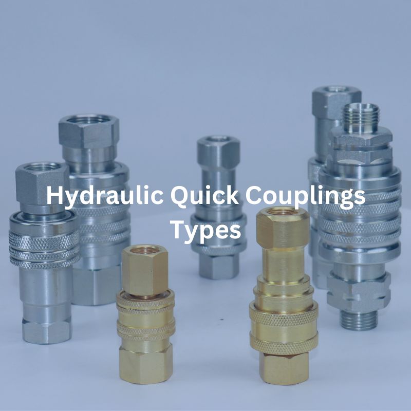
Hydraulic Quick Coupling Types: Comprehensive Guide
Table of Contents
Introduction
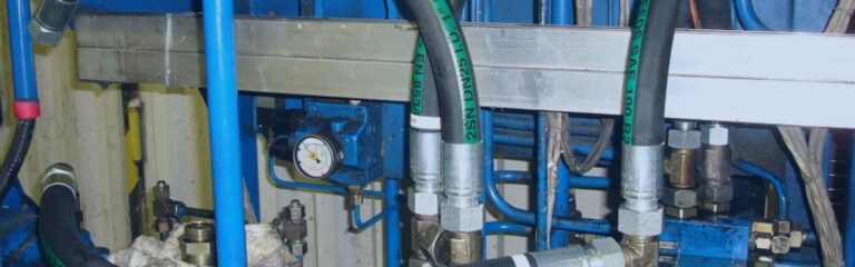
Hydraulic quick couplings enabling easy and efficient connection and disconnection of fluid lines. They are designed to ensure a leak-free and secure connection, which is essential for maintaining system pressure and performance. Quick couplings enhance system flexibility, reduce downtime, and improve safety during maintenance and operation. This guide aims to provide a comprehensive overview of hydraulic quick couplings, including their types, mechanisms, international standards, and advantages. Readers will gain insights into the selection criteria for different applications and learn about specialized couplings designed for specific industries and functions.
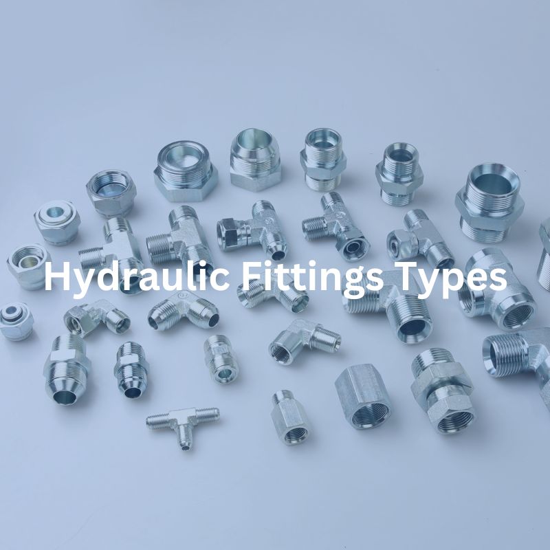
What are Common Types of Quick Couplings?
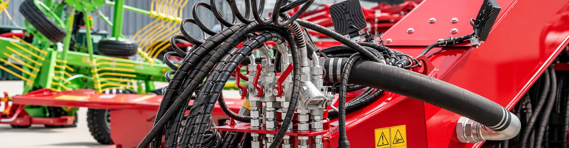
Hydraulic quick couplers common types include ball joints, which offer quick and easy connections with high reliability; flat couplings, known for their minimal fluid loss during disconnection; threaded couplings, providing secure and leak-free connections even under high pressure; and bayonet couplings, featuring a twist-and-lock mechanism for fast and secure attachment. Additionally, specialized couplings like high-flow couplings, multi-coupling plates, and leak-free couplings cater to more demanding and specific hydraulic applications.
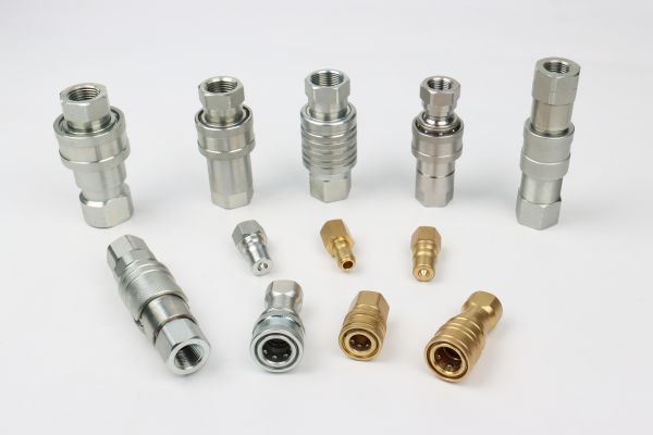
Common Types of Hydraulic Quick Couplings
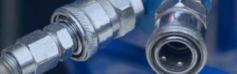
Ball Joints
Mechanisms and Designs
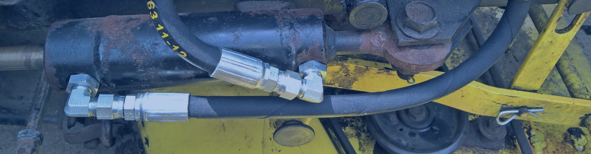
Ball joints are designed with a ball locking mechanism, which involves a series of precision-engineered balls that lock into place to ensure a secure and tight connection. This mechanism allows for quick and easy coupling and uncoupling of hydraulic lines without the need for tools, making it highly efficient for operations that require frequent connecting and disconnecting of hoses or pipes. The design of ball joints typically includes robust construction materials that can withstand high pressure and provide a reliable seal to prevent leaks.
International Standards
Ball joints comply with ISO 7241 standards, which are internationally recognized benchmarks for hydraulic quick couplings. These standards ensure that ball joint couplings are compatible and interchangeable across different hydraulic systems and manufacturers. ISO 7241 standards cover aspects such as dimensional requirements, performance specifications, and testing methods, ensuring that the couplings meet stringent quality and safety criteria.

Advantages
Quick and Easy Connection and Disconnection: The ball-locking mechanism allows for fast and effortless connection and disconnection, which reduces downtime and increases operational efficiency.
High Reliability and Minimal Leakage: The secure locking mechanism and precision engineering ensure that the connections are reliable and virtually leak-free. This is critical for maintaining system pressure and preventing fluid loss.
Flat Face Couplings
Mechanism and Design
Flat couplings are characterized by their flat-face design, which plays a crucial role in minimizing fluid loss during disconnection. This design prevents air inclusion and reduces spillage, making them highly suitable for applications where cleanliness and minimal fluid loss are essential. The flat face ensures that when the coupling is disconnected, the fluid remains contained within the system, which is particularly important in environments that require strict contamination control. These couplings are typically made from durable materials like stainless steel or brass, providing robustness and longevity.

International Standards
Flat couplings adhere to ISO 16028 standards. These standards ensure that the couplings meet rigorous performance and reliability criteria. ISO 16028 specifies the dimensional requirements, pressure ratings, and performance characteristics, ensuring that flat couplings are compatible and interchangeable with other couplings that conform to the same standards.
Advantages
Minimal Fluid Loss: The flat face design significantly reduces fluid loss during disconnection, which is crucial for maintaining system efficiency and cleanliness. This feature is particularly beneficial in applications where fluid spillage must be minimized, such as in pharmaceutical, food processing, and chemical industries.
Easy to Clean and Maintain: The simple and smooth design of flat couplings makes them easy to clean and maintain. This is an important advantage in industries where hygiene and cleanliness are paramount, as it helps prevent contamination and ensures the longevity of the coupling.
Ideal for Applications Requiring Cleanliness: Flat couplings are ideal for applications that demand high levels of cleanliness and minimal contamination. Their design helps maintain a sterile environment, making them suitable for use in medical equipment, laboratory instruments, and other sensitive applications.
Threaded Couplings
How to Operate
Threaded couplings are connected by screwing the male and female ends together. This operation involves aligning the threads on both ends and turning them until they are tightly fastened. The threaded connection ensures that the coupling remains securely in place, even under high pressure and during vigorous operation. This type of coupling is known for its robustness and the secure connection it provides, making it suitable for demanding environments.

Mechanism and Design
The threaded design of these couplings ensures a strong and reliable connection. The threads are engineered to withstand high pressure and prevent accidental disconnection. This design is particularly advantageous in applications where maintaining a secure connection is critical. The coupling’s structure typically includes durable materials such as steel or brass, which can endure high stress and resist wear over time. The threaded connection also provides a seal that helps prevent leaks and maintain system integrity.
International Standards
Threaded couplings comply with ISO 5675 and ISO 7241-1 standards. These international standards set the benchmarks for safety, performance, and compatibility. ISO 5675 specifies the requirements for agricultural equipment couplings, while ISO 7241-1 outlines the general requirements for hydraulic quick couplings. Compliance with these standards ensures that the couplings are safe to use, meet high-performance criteria, and are compatible with other standardized components.
Bayonet Couplings
Connection Methods
Bayonet couplings use a twist-and-lock mechanism that enables a secure and quick connection. To connect, the male and female ends are aligned and then twisted together, locking them into place. This method allows for a fast and straightforward operation, making bayonet couplings highly efficient for applications that require frequent connecting and disconnecting of hydraulic lines.
Mechanism and Design
The bayonet design is engineered for easy and rapid connection and disconnection. This mechanism is particularly beneficial in environments where quick changes are necessary, such as in emergency or field service situations. The twist-and-lock design ensures that the connection is secure, preventing accidental disconnection while in use. Bayonet couplings are typically constructed from robust materials like stainless steel or brass, providing durability and longevity even under demanding conditions.
International Standards
Bayonet couplings meet ISO 16028 and MIL-C-39029 standards. ISO 16028 pertains to hydraulic quick couplings with a flat face design, ensuring high performance and reliability. MIL-C-39029 is a military standard that specifies the requirements for electrical connectors, ensuring they meet stringent durability and performance criteria.
Wing Nut Coupling

Connection Methods
Wing nut couplings are connected using a threaded mechanism combined with a wing nut, which allows for easy hand-tightening. The wing nut provides a larger gripping surface, making it easier to tighten or loosen the connection without the need for tools. This makes them particularly user-friendly and convenient for applications where frequent connections and disconnections are required.
Mechanism and Design
The design of wing nut couplings includes a robust threaded connection that ensures a secure and leak-free seal. The wing nut itself is designed with ergonomic wings that provide leverage for easy hand operation. This design is beneficial in situations where quick assembly or disassembly is needed without the availability of wrenches or other tools. The coupling is typically constructed from durable materials such as brass, stainless steel, or heavy-duty plastic, depending on the application requirements.
International Standard
Wing nut couplings comply with standards such as ISO 14540, which specifies the requirements for quick-release couplings for use in hydraulic systems. These standards ensure that the couplings are safe, reliable, and compatible with other components in the hydraulic system.
Push and Pull Quick Coupling
Connection Methods
Push and pull quick couplings are designed for rapid connection and disconnection by simply pushing the male end into the female end to connect, and pulling it apart to disconnect. This mechanism allows for a swift and effortless operation without the need for additional tools, making them ideal for applications that require frequent and quick connections.

Mechanism and Design
The push and pull design incorporates an internal locking mechanism that securely holds the coupling in place once connected. Typically, this involves a series of balls or a sleeve that engages when the male and female ends are pushed together. The coupling is released by pulling back on a sleeve or collar, which disengages the locking mechanism. These couplings are often constructed from durable materials like brass, stainless steel, or reinforced plastics to ensure longevity and reliability under various operating conditions.
International Standards
Push and pull quick couplings adhere to standards such as ISO 7241-1, which covers the requirements for hydraulic quick couplings. These standards ensure that the couplings meet specific performance, safety, and compatibility criteria, making them reliable and interchangeable with other standardized components.
Selection Criteria for Hydraulic Quick Couplings
Choosing the right hydraulic quick couplings for your system involves considering several key factors to ensure optimal performance, reliability, and safety. Here are the primary selection criteria:
Pressure Rate
Understanding Pressure Requirements
Hydraulic systems operate under a wide range of pressure conditions, depending on the specific application and system design. The pressure within a hydraulic system can vary due to factors such as fluid flow rates, load conditions, and the type of hydraulic fluid used. It is crucial to select couplings that can withstand these varying pressure conditions to prevent system failure, ensure safety, and maintain efficient operation.
When assessing the pressure requirements of your hydraulic system, consider both the normal operating pressure and any potential pressure spikes that may occur during operation. Pressure spikes can result from sudden changes in load, rapid valve closures, or other dynamic conditions within the system. These spikes can significantly exceed the normal operating pressure, and couplings must be able to handle these transient conditions without failure.
Selecting Couplings According to System Pressure
Identify the Maximum Operating Pressure of Your Hydraulic System:
Start by determining the maximum pressure that your hydraulic system will encounter during normal operation. This information can typically be found in the system specifications, design documentation, or through direct measurement.
Choose Couplings That Are Rated for at Least This Pressure:
Once you have identified the maximum operating pressure, select couplings that are rated for at least this pressure. The pressure rating of a coupling indicates the maximum pressure it can safely handle without risk of failure. It is advisable to choose couplings with a pressure rating that exceeds the maximum operating pressure of your system to provide a safety margin.
Consider a Safety Margin:
Adding a safety margin to the pressure rating of the couplings is a best practice. A common approach is to select couplings with a pressure rating that is 1.5 to 2 times the maximum operating pressure of your system.
Flow Rate
How Flow Rate Affects Coupling Performance
The flow rate, measured in gallons per minute (GPM) or liters per minute (LPM), is a critical parameter in hydraulic systems as it determines the volume of fluid that can pass through the coupling within a specified time frame. The flow rate directly impacts the system’s efficiency, performance, and overall functionality.
Selecting a coupling with the appropriate flow rate is essential to avoid creating bottlenecks in the hydraulic system. Suppose the flow rate of the coupling is too low for the system’s requirements. In that case, it can restrict fluid movement, leading to increased pressure drops, reduced system efficiency, and potential overheating of the hydraulic fluid. Conversely, a coupling with a flow rate that exceeds the system’s needs can lead to unnecessary costs and potential mismatches with other system components.
Selecting the Right Flow Rate for Your System
Determine the Required Flow Rate for Your System’s Optimal Performance:
System Analysis: Begin by analyzing your hydraulic system to determine the flow rate required for optimal performance. This involves understanding the demands of the hydraulic components, such as pumps, motors, and actuators, and how they interact within the system.
Manufacturer Specifications: Refer to the specifications provided by the manufacturers of your hydraulic equipment. These specifications typically include recommended flow rates for optimal operation.
Select Couplings That Can Handle This Flow Rate:
Coupling Specifications: Choose hydraulic quick couplings that are rated for the flow rate identified in your system analysis. Ensure that the couplings can handle the maximum flow rate without causing excessive pressure drops or turbulence, which can negatively affect system performance.
Size and Design Considerations: The size and internal design of the coupling play a significant role in determining its flow capacity. Larger couplings with streamlined internal passages typically offer higher flow rates and lower pressure drops.
Compatibility and Interchangeability: Ensure that the selected couplings are compatible with other components in your hydraulic system. Consider standardization and interchangeability to facilitate maintenance and replacements.
Assess Performance Under Different Conditions:
Variable Flow Rates: Hydraulic systems often operate under varying conditions, which can affect the flow rate. Ensure that the chosen couplings can maintain their performance across the full range of operating conditions, including different pressures, temperatures, and fluid viscosities.
Pressure Drop Considerations: Evaluate the pressure drop across the coupling at the required flow rate. Excessive pressure drops can reduce system efficiency and lead to performance issues. Choose couplings that minimize pressure drop while maintaining the necessary flow rate.
Common Materials
The material of a hydraulic quick coupling plays a crucial role in determining its durability, resistance to corrosion, and suitability for various environments. Different materials offer distinct advantages and are chosen based on the specific requirements of the application. Here are the common materials used in hydraulic quick couplings:
Steel
Steel is known for its high strength and durability, making it suitable for high-pressure applications. It can withstand significant mechanical stress and is less prone to deformation under heavy loads.
Brass
Brass is an alloy of copper and zinc, known for its excellent corrosion resistance, especially in environments where exposure to water or moisture is common. It also offers good mechanical properties but is generally used in lower-pressure applications compared to steel and stainless steel.
Stainless Steel
Stainless steel is an alloy known for its high strength, durability, and exceptional resistance to corrosion and rust. It is ideal for applications in harsh environments, including those with high pressure, extreme temperatures, and exposure to corrosive substances.
Environmental Factors
Environmental conditions play a crucial role in determining the performance and longevity of hydraulic quick couplings. Various environmental factors, such as temperature extremes, corrosive environments, and chemical exposure, can impact the functionality and durability of couplings.
Temperature
Operating Temperature Range: Hydraulic systems can operate in a wide range of temperatures, from very low to very high. It is important to ensure that the coupling material and seals can handle the full spectrum of temperatures they will encounter.
Material Selection: Materials such as stainless steel and high-grade brass can withstand a wide temperature range without losing strength or integrity. Additionally, seals made from materials like Viton or Teflon are designed to perform well in extreme temperatures.
Thermal Expansion: Consider the thermal expansion properties of the coupling material. Materials that expand or contract significantly with temperature changes can affect the coupling’s performance and sealing capability.
Corrosion
Environmental Exposure: In environments with high humidity, salt, or chemical exposure, corrosion resistance is a key factor. Corrosive environments can lead to the degradation of coupling materials, causing leaks and failures.
Material Selection: Stainless steel is highly resistant to corrosion and is ideal for harsh environments such as marine or coastal areas, chemical processing plants, and food processing facilities. Alternatively, specially coated steel (e.g., zinc-plated or galvanized) can offer enhanced corrosion resistance.
Chemical Exposure
Compatibility with Hydraulic Fluids: Verify that the coupling materials and seals are compatible with the hydraulic fluids used in your system. Some hydraulic fluids can be aggressive and may cause certain materials to degrade over time.
Chemical Compatibility: Consider all chemicals the couplings might come into contact with, including cleaning agents, solvents, and process fluids. For aggressive chemical environments, materials like stainless steel and seals made from chemical-resistant compounds (e.g., Viton, EPDM) are recommended.
Material Resistance: Use materials that are specifically designed to resist the chemical agents in your application. For example, PTFE seals are highly resistant to a wide range of chemicals and are suitable for demanding chemical applications.
Conclusion
Hydraulic quick couplings are important components in hydraulic systems that provide efficient and reliable connections and disconnections for a variety of applications. Each type has unique features, mechanisms, and criteria that make them suitable for specific applications. By understanding the specific requirements of your hydraulic system and the environmental conditions in which it operates, you can make an informed decision when selecting a hydraulic quick coupling.
If you still have a lot of doubts about hydraulic quick couplings, feel free to contact Topa!
FAQ
What are the main types of hydraulic quick couplers?
The main types include ball joints, flat face couplings, threaded couplings, bayonet couplings, wing nut couplings, and push and pull quick couplings.
What is the advantage of ball joint couplings?
Ball joint couplings offer quick and easy connection and disconnection, high reliability, and minimal leakage, making them versatile for various applications.
Why are flat face couplings preferred in clean environments?
Flat face couplings minimize fluid loss during disconnection and are easy to clean, making them ideal for applications requiring high levels of cleanliness.
What makes threaded couplings suitable for heavy-duty applications?
Threaded couplings provide a robust and secure connection, capable of withstanding high pressure and preventing accidental disconnection, making them ideal for heavy-duty applications.
How do bayonet couplings work?
High flow couplings handle large volumes of fluid at high pressures, ensuring efficient operation in industrial, construction, and agricultural equipment.
What are the benefits of using high flow couplings?
Key factors include the pressure rating, fluid compatibility, environmental conditions (such as temperature and exposure to chemicals), and the specific application requirements.


