Hydraulic Flange fitting size chart Topa

Hydraulic Flange Fitting Size Chart

Hydraulic Flange Fitting Size Chart: Your Ultimate Guide

Table of Contents

Introduction

Hydraulic flange fittings play a crucial role in ensuring leak-free and efficient hydraulic systems. Understanding the correct sizing of these fittings is essential for system performance and safety. This guide aims to provide a comprehensive resource on hydraulic flange fitting size charts, helping you make informed decisions for your hydraulic applications.

Understanding Hydraulic Flange Fittings

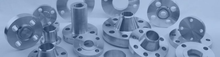
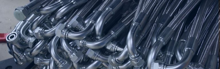
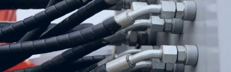
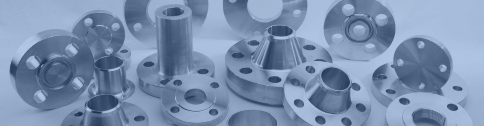
Hydraulic flange fittings are essential for connecting pipes, hoses, and tubes in hydraulic systems. They provide secure, leak-free connections that withstand high pressures. Here are the primary types:

NPT/NPTF (National Tapered Pipe/Fuel)

SAE Code 61: Used for standard pressure applications, typically up to 3000 psi.

SAE Code 62: Designed for high-pressure applications, handling pressures up to 6000 psi.

ISO 6162: An international standard covering both Code 61 and Code 62 flange fittings, ensuring global compatibility and consistency.

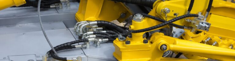
These fittings are widely used across various industries, including automotive, aerospace, and manufacturing, due to their reliability and robustness.

SAE Code 61: These fittings are ideal for lower to medium-pressure hydraulic systems. They have a robust design that ensures a strong, leak-free connection. Common applications include mobile equipment, agricultural machinery, and industrial hydraulic systems.

SAE Code 62: These fittings are designed for high-pressure applications, making them suitable for more demanding hydraulic systems. They are used in heavy machinery, construction equipment, and high-pressure industrial applications. Their ability to withstand higher pressures makes them indispensable in situations where system integrity and safety are critical.

ISO 6162: This standard encompasses both SAE Code 61 and Code 62 fittings, providing a unified specification that ensures compatibility across different regions and manufacturers. ISO 6162 fittings are versatile and widely accepted in international markets, facilitating global trade and system standardization.

Importance of Accurate Sizing

Selecting the correct size for hydraulic flange fittings is crucial to maintaining system integrity and efficiency. Incorrect sizing can lead to leaks, system failures, and significant safety hazards. Ensuring the right size offers several key benefits:

Optimal System Performance: Properly sized fittings maintain the desired pressure levels and fluid flow, enhancing overall system efficiency.

Extended Lifespan: Correct sizing minimizes wear and tear on components, reducing the need for frequent replacements and maintenance.

Enhanced Safety and Reliability: Accurate sizing prevents leaks and bursts, ensuring a safer working environment and reliable system operation.

Preventing System Failures

Incorrectly sized hydraulic flange fittings can compromise the entire hydraulic system. When the fitting is too small, it restricts fluid flow, leading to increased pressure and potential system overload. Conversely, an oversized fitting may cause connections to be loose, resulting in leaks. Both scenarios can cause significant operational disruptions and costly repairs.

Safety Hazards

Safety is paramount in any hydraulic system. Leaks resulting from improperly sized fittings can lead to hazardous working conditions, including the risk of hydraulic fluid exposure and potential fire hazards. Ensuring that fittings are correctly sized mitigates these risks, providing a safer environment for operators and technicians.

Tips for Ensuring Accurate Sizing

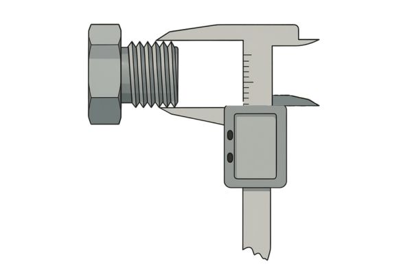
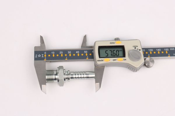
Measure Precisely: Use accurate tools like calipers to measure the diameter, bolt circle diameter, and other critical dimensions of your fittings.

Consult Size Charts: Refer to detailed hydraulic flange fitting size charts to match your measurements with the correct fitting size.

Consider Application Requirements: Ensure the fitting size matches the specific needs of your application, including pressure and flow requirements.

Verify Standards Compliance: Ensure the fittings adhere to industry standards such as SAE or ISO to guarantee compatibility and performance.

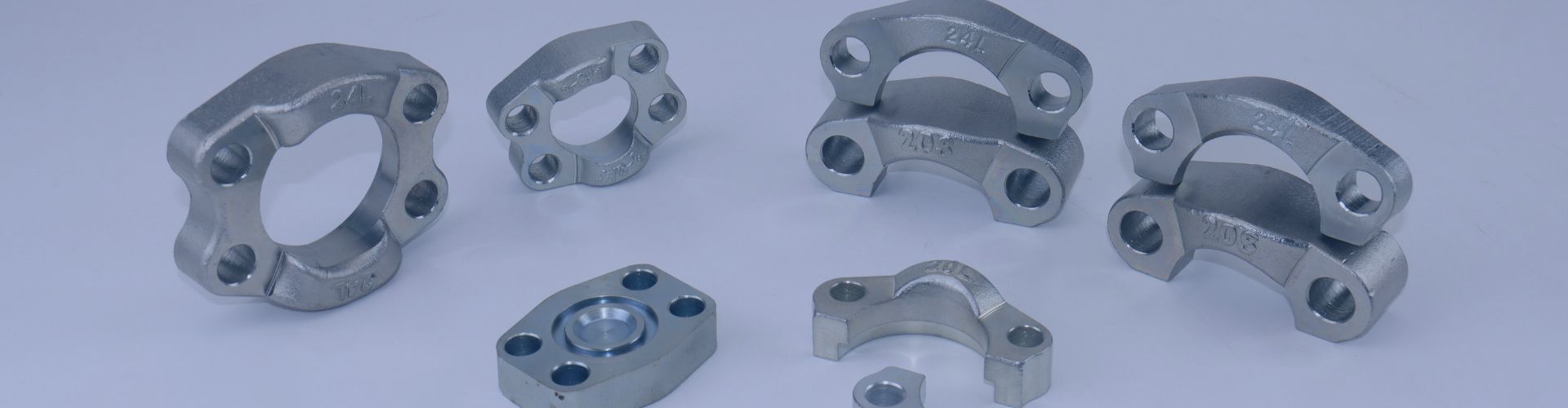
Components of a Hydraulic Flange Hose Fitting Size Chart

Flange fitting size chart Topa

A hydraulic flange hose fitting size chart is essential for ensuring the correct selection and compatibility of fittings in hydraulic systems. Here’s a detailed breakdown of the key components identified from the provided image:

Part Number:

A unique identifier for each fitting type facilitates precise selection and ordering.

Flange Size:

The nominal size of the flange, typically measured in inches, indicates the fitting’s general size category.

Hose I.D. (Inner Diameter):

The internal diameter of the hose is crucial for ensuring the hose fits properly with the fitting and maintains optimal flow capacity.

Dimensions:

Length:

The overall length of the fitting from end to end, is measured in both inches and millimeters. This measurement is crucial for determining the fitting’s reach and ensuring it fits within the system’s spatial constraints.

Flange Diameter:

The diameter of the flange face is critical for matching the fitting to the system’s flange specifications. This ensures a proper seal and secure connection.

Bolt Circle Diameter:

The distance between the centers of the bolt holes is essential for aligning the flange fitting correctly and securing it tightly to prevent leaks and maintain system integrity.

Additional Material Options:

Information indicating the availability of fittings in different materials, such as stainless steel, is important for applications requiring specific material properties for durability, corrosion resistance, and compatibility with various hydraulic fluids.

Measurement Steps

Follow these steps to measure each dimension of the hydraulic flange fitting:

Measuring Hose End Inner Diameter (Hose I.D.)

Prepare the Hose: Lay the hose flat, ensuring it is not compressed or deformed.

Measure with a Caliper: Use a vernier caliper to measure the inner diameter of the hose. Open the caliper’s jaws and insert them inside the hose. Ensure the caliper’s jaws are touching the inner walls of the hose.

Record the Measurement: Note down the measurement for future reference.

Measuring Length

Position the Flange Fitting: Place the flange fitting flat on a level surface, making sure it is fully extended.

Use a Measuring Tape or Ruler: Measure the total length of the flange fitting from one end to the other using a measuring tape or a steel ruler.

Record the Measurement: Write down the measured length accurately.

Measuring Flange Diameter

Position the Flange: Place the flange flat on a level surface.

Measure with a Caliper or Ruler: Use a vernier caliper or a steel ruler to measure the outer diameter of the flange at its widest point.

Record the Measurement: Note down the flange diameter measurement.

Measuring Bolt Circle Diameter

Position the Flange: Lay the flange flat on a level surface.

Identify Bolt Holes: Locate two opposite bolt holes on the flange.

Measure with a Measuring Tape: Use a measuring tape to measure the distance between the center points of the two opposite bolt holes.

Record the Measurement: Write down the bolt circle diameter measurement.

Practical Tips for Choosing the Right Flange Fitting

Consider Pressure Rating

Maximum Pressure

When selecting a hydraulic flange fitting, it is critical to ensure that the fitting can handle the highest pressure your system will encounter. This involves understanding the system’s maximum operating pressure and comparing it to the pressure rating of the fitting. Using a fitting that cannot withstand the required pressure can result in leaks or catastrophic failures, posing serious safety risks and potentially causing extensive damage to the system.

System Fluctuations

Hydraulic systems often experience pressure spikes and fluctuations. It is essential to account for these variations by choosing a fitting with a safety margin above the regular operating pressure. This buffer helps accommodate unexpected surges and ensures that the fitting remains secure and functional under varying pressure conditions. Selecting a fitting with a higher pressure rating than the maximum operating pressure provides an additional layer of safety and reliability, helping to prevent failures and maintain system integrity.

Detailed Considerations

Pressure Rating Labels:

Always check the manufacturer’s specifications for the pressure rating, typically labeled in psi (pounds per square inch) or bar. These ratings indicate the maximum pressure the fitting can safely withstand.

Safety Margins:

Implement a safety margin of at least 1.5 to 2 times the system’s normal operating pressure. For instance, if your system operates at 3000 psi, consider fittings rated for at least 4500 to 6000 psi.

Pressure Testing:

Regularly test your system under controlled conditions to ensure that fittings perform well within the expected pressure ranges. Periodic testing can help identify potential weaknesses before they lead to failures.

Material Compatibility

Hydraulic Fluid

When choosing fittings, ensure they are made from materials compatible with the specific type of hydraulic fluid used in your system. Different fluids can react differently with various metals. For example, some hydraulic fluids may be corrosive to aluminum but not to stainless steel. Compatibility is crucial to prevent chemical reactions that can lead to corrosion, degradation, and system failure.

Operating Environment

Consider environmental factors such as temperature, exposure to chemicals, and humidity. Material selection should account for these conditions:

Stainless Steel: Ideal for corrosive environments and high-humidity areas due to its excellent resistance to rust and chemical reactions.

Carbon Steel: Suitable for less demanding conditions where corrosion resistance is not as critical. It is often used in standard industrial applications.

Brass or Bronze: Can be used in situations where metal flexibility and corrosion resistance to specific chemicals are needed.

Installation Practices

Proper installation of hydraulic flange fittings is essential to ensure a secure and leak-free connection. Here are some best practices to follow:

Alignment

Proper Alignment: Ensure that fittings are properly aligned during installation. Misalignment can cause undue stress on the fittings and lead to potential leaks or system failures. Use alignment tools if necessary to maintain precision.

Torque Specifications

Manufacturer’s Specifications: Always adhere to the torque specifications provided by the manufacturer. Over-tightening bolts can damage fittings and threads, while under-tightening can result in insufficient sealing and leaks. Use a calibrated torque wrench to achieve the correct torque.

Even Tightening

Crisscross Pattern: Tighten bolts in a crisscross pattern to ensure even pressure distribution across the flange. This method prevents warping or uneven sealing, which can compromise the integrity of the connection. Start by tightening bolts to a fraction of the final torque, then gradually increase to the full torque in multiple passes.

Detailed Considerations

Pre-Installation Checks:

Inspect all components for damage or defects before installation.

Ensure that all surfaces are clean and free of debris to prevent contamination and ensure a proper seal.

Use of Lubricants:

Apply appropriate lubricants to bolts and threads to achieve accurate torque readings and prevent galling (seizing or sticking of metal parts).

Post-Installation Inspection:

After installation, conduct a thorough inspection to verify the correct alignment and torque. Check for any signs of leaks or misalignment and rectify them immediately.

Additional Tips

Temperature Ratings

Operating Temperatures: Ensure that the fitting material can withstand the operating temperatures of your system without degrading or losing integrity. Different materials have varying levels of temperature resistance, so select accordingly.

Maintenance and Inspection

Regular Inspections: Routinely check your fittings for signs of wear, corrosion, or damage. Early detection of issues can prevent minor problems from escalating into major failures.

Timely Maintenance: Replace worn or damaged fittings promptly to maintain the system’s performance and safety. Regular maintenance helps in extending the lifespan of the hydraulic components and ensures consistent operation.

Conclusion

In this guide, we have explored the critical aspects of hydraulic flange hose fittings, including the importance of accurate sizing, understanding key components of the size chart, adhering to common standards and specifications, practical tips for selecting the right fittings, and best practices for installation and maintenance. Apply the knowledge gained from this guide to select and maintain your hydraulic fittings effectively, enhancing your hydraulic system’s longevity and functionality.

FAQ

What are hydraulic hose flanges?

Hydraulic hose flanges are fittings used to connect hoses in hydraulic systems, ensuring a secure and leak-free connection capable of withstanding high pressures.

How do I measure a hydraulic flange?

Use calipers or a measuring tape to measure the flange diameter, bolt circle diameter (BCD), bolt size, and port size.

What is the difference between SAE Code 61 and Code 62?

SAE Code 61 is for medium-pressure applications, while Code 62 is for high-pressure applications.

What materials are hydraulic flanges made from?

Common materials include stainless steel, carbon steel, and alloy steel, chosen based on compatibility with hydraulic fluids and environmental conditions.

Why is proper alignment important during installation?

Proper alignment prevents undue stress and potential leaks, ensuring a secure and efficient connection.

How often should I inspect my hydraulic flange fittings?

Regular inspections should be conducted to check for signs of wear, corrosion, or damage, ideally during routine maintenance schedules.

Metric Hydraulic Fitting Identification Topa

Metric Hydraulic Fitting Identification

Metric Hydraulic Fitting Identification: Step-by-Step Guide

Table of Contents

Introduction

Metric hydraulic fittings are widely used due to their standardized measurements and compatibility with international systems. Accurate identification of these fittings is essential to maintain system integrity and avoid costly downtime. This guide aims to provide a comprehensive, step-by-step process for identifying metric hydraulic fittings, ensuring that you can accurately match and replace fittings in your hydraulic systems.

Understanding Metric Hydraulic Fittings

Metric hydraulic fittings are connectors designed to join sections of hydraulic hose, pipe, and tubing in a hydraulic system. These fittings are measured using the metric system, which is based on millimeters. They play a vital role in maintaining the flow of hydraulic fluid, thereby ensuring the proper operation of machinery.

Types of Metric Hydraulic Fittings

DIN 24° Fittings

DIN 24° fittings feature a 24-degree cone seat and are a staple in European hydraulic systems. They come in both light (L) and heavy (S) series, differentiated by wall thickness and pressure capacity, ensuring a reliable metal-to-metal seal for high-pressure application

Metric Standpipe Fittings

Metric standpipe fittings are straight connectors typically used for joining two hydraulic hoses or a hose to a machine component. They are essential in systems requiring a straightforward, high-integrity connection, especially in heavy machinery and industrial applications.

Metric Flange Fittings

Metric flange fittings connect hydraulic hoses and pipes using a flange system that bolts directly to components. They are employed in high-pressure environments where a secure, rigid connection is necessary, often in industrial and mobile hydraulic systems.

Compression Fittings

Compression fittings use a ferrule to compress the pipe as the fitting is tightened, ensuring a leak-proof connection. These fittings are used in hydraulic systems where reliable, easy-to-install connections are required, often in instrumentation and low to medium-pressure applications.

Parallel Threads

Maintain a constant diameter along the thread length. They typically require an additional sealing method, such as an O-ring or bonded seal, to ensure a leak-proof connection.

Tapered Threads

Decrease in diameter along the thread length, creating a seal through thread deformation. These threads can provide a reliable seal without additional sealing components.

Step-by-Step Identification Process

Determine the Metric Thread Type

Topa metric fitting

Identifying the thread type is the first and most crucial step in the identification process. Understanding whether the thread is parallel or tapered helps determine the appropriate sealing method and fitting compatibility. Here’s a detailed guide to determine the metric thread type:

Visual Inspection

Parallel Threads:

  • Description: Parallel threads maintain a consistent diameter along their entire length. When you measure the diameter at different points along the thread, it should remain the same.
  • Identification: Visually inspect the threads to see if they appear straight and uniform without tapering. These threads typically rely on an additional sealing mechanism, such as an O-ring, to ensure a leak-free connection.

Tapered Threads:

  • Description: Tapered threads gradually decrease in diameter from the base to the tip. This tapering helps create a tight seal as the threads are screwed together.
  • Identification: Observe the threads to check if they taper. Measure the diameter at several points along the length to confirm the tapering effect. The reduction in diameter is a clear indicator of tapered threads.

Use of Thread Gauges

Parallel Threads:

  • Fit: When using a thread gauge on parallel threads, the gauge should fit uniformly without any gaps along the length of the thread.
  • Procedure: Select the appropriate gauge for the estimated pitch and insert it into the threads. If the gauge fits snugly and evenly, it confirms the presence of parallel threads.

Tapered Threads:

  • Fit: For tapered threads, the thread gauge will fit tightly at one end and loosely at the other, reflecting the gradual decrease in diameter.
  • Procedure: Choose a thread gauge corresponding to the estimated pitch and insert it into the threads. If the gauge fits tightly at the start and becomes looser as it moves along the thread, this indicates a tapered thread.
hydraulic fittings measure tools Topa

Measurement with Calipers

  • Step-by-Step: Use a caliper to measure the thread’s outside diameter. Ensure the caliper is perpendicular to the thread axis to obtain an accurate reading.
  • Multiple Points: Measure the diameter at several points along the thread to determine if the diameter remains constant or changes.

Parallel Threads:

  • Consistency: Measure the diameter at different points along the thread. If the measurements are consistent, the threads are parallel.
  • Verification: Consistent measurements indicate the thread is parallel, confirming the absence of tapering.

Tapered Threads:

  • Decrease: Measure the diameter at multiple points along the thread. A noticeable decrease in diameter confirms the presence of tapered threads.
  • Verification: The decreasing measurements at different points along the thread indicate it is tapered, confirming the tapering effect.

Thread Form and Pitch

Metric Thread Pitch:

  • Measurement: Use a pitch gauge to measure the distance between threads. Insert the pitch gauge into the threads to determine the correct pitch.
  • Common Pitches: Common metric thread pitches include 1.0mm, 1.5mm, and 2.0mm. Ensure the pitch gauge fits snugly into the threads without any gaps.

Identifying the Form:

  • Thread Profile: Examine the thread profile and angle. Metric threads typically have a 60-degree thread angle, which is standard across various types.
  • Visual and Measurement: Use both visual inspection and measurement tools to identify the thread form. Ensure the threads match the 60-degree angle typically associated with metric threads.

Measure the Thread Diameter

Accurate measurement of the thread diameter is essential for correct fitting identification. Here’s a detailed guide to measuring the thread diameter using calipers:

Preparation

Clean the Threads:

  • Importance: Ensure that the threads are clean and free of debris or damage. Dirt or damage can distort measurements, leading to incorrect identification.
  • Method: Use a brush or cloth to clean the threads thoroughly, removing any dirt, grease, or residue.

Select the Correct Calipers:

  • Type: Use digital or vernier calipers for precise measurements. Digital calipers provide easy-to-read results, while vernier calipers offer high accuracy with a manual scale.
  • Calibration: Ensure that the calipers are calibrated correctly before use to guarantee accurate measurements.

Positioning the Calipers

Perpendicular Alignment:

  • Importance: Position the calipers perpendicularly to the axis of the thread. This ensures that the measurement is taken at the correct angle and not skewed.
  • Technique: Hold the calipers steady and make sure they are aligned straight across the thread peaks (crests).

Correct Placement:

  • Placement: Place the caliper jaws on the outermost points of the thread peaks (the crests). Avoid placing the calipers on the thread roots (the valleys), as this will give an incorrect diameter reading.
  • Precision: Make sure the calipers are centered and not off to one side, which could affect the measurement accuracy.
measure metric hydraulic fitting

Taking the Measurement

Initial Measurement:

  • Procedure: Gently close the caliper jaws around the thread crests. Ensure that the calipers are not applying too much pressure, as this can compress the threads and give a false reading.
  • Care: Close the calipers slowly to avoid damaging the threads or the caliper itself.

Reading the Calipers:

  • Digital Calipers: Read the measurements displayed on the digital calipers. The digital readout will provide a precise and immediate measurement.
  • Vernier Calipers: If using vernier calipers, read the scale accurately. Align the vernier scale with the main scale to determine the precise measurement.

Double-Checking for Accuracy

Multiple Measurements:

  • Consistency: Take multiple measurements at different points along the thread length to ensure consistency. This helps to confirm that the thread diameter is uniform and the measurement is accurate.
  • Technique: Measure at the start, middle, and end of the threaded section to detect any variations.

Cross-Verification:

  • Reference Charts: Compare the measured diameter with standard thread diameter charts to verify accuracy. This step is crucial to ensure that the measured value matches standard dimensions for the specific thread type.
  • Confirmation: Use reputable sources or manufacturer specifications to cross-check the measurements.

Common Pitfalls to Avoid

Measuring at an Angle:

  • Error: Ensure that the calipers are not tilted or angled when taking the measurement. An angled measurement will give a larger or smaller diameter than the actual value.
  • Solution: Double-check the alignment of the calipers and adjust as needed to ensure they are perpendicular to the thread axis.

Damaged Threads:

  • Caution: Be cautious when measuring worn or damaged threads. In such cases, it may be necessary to take an average of multiple measurements or refer to original specifications if available.
  • Technique: Measure in several places and use the most consistent readings, or consult the fitting’s original design specifications for accurate dimensions.

Identify the Thread Pitch

Identifying the thread pitch is a critical step in the process of metric hydraulic fitting identification. The thread pitch is the distance between threads, measured in millimeters for metric threads. Here’s a detailed guide to accurately determine the thread pitch using thread gauges:

Using the Thread Gauge

Insert the Gauge:

  • Selection: Begin by selecting a thread gauge that you estimate to be close to the pitch of the thread you are measuring. This initial selection can be based on visual estimation or experience.
  • Insertion: Carefully insert the gauge into the threads of the fitting, ensuring it aligns with the thread grooves.

Check for Fit:

  • Snug Fit: Ensure the gauge fits snugly into the threads without any gaps. A proper fit means that the gauge’s teeth should align perfectly with the tread grooves.
  • Visual Inspection: Visually inspect to confirm that the gauge sits neatly in the thread grooves without any visible gaps or misalignment.
ring gauge Topa

Identifying the Correct Pitch

Trial and Error:

  • Multiple Gauges: If the first gauge does not fit correctly, try gauges with different pitches until you find one that fits snugly. This process may require several attempts with different sizes.
  • Adjustment: Slight adjustments and multiple trials help ensure the most accurate match.

Snug Fit:

  • Alignment: The correct gauge will sit neatly in the thread grooves without any play or misalignment. This indicates that the pitch of the gauge matches the pitch of the threads.
  • Verification: Confirm that the gauge fits securely along the entire length of the thread.

Verify Fit:

  • Rotation: Double-check the fit by slightly rotating the gauge in the threads. If it continues to fit snugly without slipping or binding, you have identified the correct pitch.
  • Consistency: Ensure the gauge remains aligned and fits securely through minor adjustments.

Common Metric Thread Pitches

Examples:

Common metric thread pitches include 0.5mm, 0.75mm, 1.0mm, 1.5mm, and 2.0mm. For hydraulic fittings, pitches like 1.0mm, 1.5mm, and 2.0mm are frequently encountered.

Standard Sizes:

Use reference charts to cross-check the pitch size. These charts list standard thread pitches for various fitting types and sizes, helping confirm your measurements.

Documentation

Record the Measurement:

  • Documentation: Once the correct thread pitch is identified, note it down along with the previously measured thread diameter. This documentation is crucial for cross-referencing and ensuring the accuracy of the fitting identification.
  • Accuracy: Proper documentation helps in future reference and verification, ensuring that the fitting type is accurately identified.

Common Challenges and Solutions

Incorrect Measurements

To avoid incorrect measurements, always use calibrated tools and measure multiple times. Calibrated tools ensure precision, and multiple measurements at different points along the thread help confirm consistency. Ensure the tools are properly positioned; the calipers should be perpendicular to the thread axis and placed correctly on the thread crests. Additionally, the fitting must be clean and undamaged, as dirt or deformations can lead to inaccurate readings. By maintaining clean threads and using precise, calibrated instruments, you can significantly reduce the risk of measurement errors.

Identifying Worn or Damaged Threads

Worn or damaged threads can complicate the identification process, as they may not match standard profiles. To address this, use thread repair tools to restore the thread profile to its original shape. These tools can help smooth out deformities and make the threads easier to measure accurately. If thread repair is not feasible, refer to the original equipment specifications or documentation to find the correct thread size and type. This approach ensures that even if the threads are damaged, you can still identify the fitting accurately by cross-referencing with the original specifications.

Distinguishing Similar Thread Types

Accurately identifying metric hydraulic fittings is essential for maintaining the efficiency and reliability of hydraulic systems. By following this step-by-step guide and utilizing the appropriate tools and reference materials, you can ensure precise fitting identification and avoid potential system failures. Use the steps and resources provided to enhance your maintenance practices and keep your hydraulic systems running smoothly.

If you need any kind of metric hydraulic fittings, please contact Topa and we will arrange it for you as soon as possible!

FAQ

What tools are essential for identifying metric hydraulic fittings?

Essential tools include calipers, thread gauges, a magnifying glass, and reference charts. Ensure all tools are calibrated and specifically designed for metric threads.

How can I distinguish between parallel and tapered threads?

Measure the thread diameter at multiple points along its length. Parallel threads maintain a consistent diameter, while tapered threads show a decrease in diameter from base to tip.

What should I do if the threads are worn or damaged?

Use thread repair tools to restore the thread profile. If repair is not possible, refer to the original equipment specifications to determine the correct thread size and type.

How do I accurately measure the thread pitch?

Clean the threads and use a thread gauge set with various pitch sizes. Insert the gauge into the threads and ensure it fits snugly without gaps. Double-check the fit by rotating the gauge slightly.

What are common metric thread pitches used in hydraulic fittings?

Common metric thread pitches include 0.5mm, 0.75mm, 1.0mm, 1.5mm, and 2.0mm. For hydraulic fittings, 1.0mm, 1.5mm, and 2.0mm pitches are frequently encountered.

How can I differentiate between similar metric thread types?

Utilize detailed reference charts to compare measurements. Seek expert advice or consult manufacturer documentation if needed to ensure accuracy. This helps distinguish closely related thread types accurately.

Hydraulic Fitting Identification Everything You Need to Know

Hydraulic Fitting Identification

Hydraulic Fitting Identification: The Detail Guide

Table of Contents

Introduction

Proper identification of hydraulic fittings is crucial for ensuring the safety, efficiency, and longevity of hydraulic systems. Accurate identification helps prevent leaks, minimizes downtime, and reduces maintenance costs. Understanding the different types of hydraulic fittings and their specifications can be challenging, but it’s essential for maintaining system integrity and performance. In this post, we’ll explore the importance of correct hydraulic fitting identification and provide a comprehensive guide to help you identify threads, hose ends, and connectors accurately.

Identifying Hydraulic Threads

Identifying hydraulic threads correctly is vital to ensure compatibility and prevent leaks. Mismatched threads can lead to system failures, posing safety risks and incurring significant costs. Proper thread identification helps maintain the efficiency and reliability of hydraulic systems. Threads are the critical points where hydraulic components connect, and any inconsistency or inaccuracy in matching these threads can result in significant operational issues. For example, a mismatched thread may not form a proper seal, leading to fluid leaks that compromise system performance and safety. Moreover, using the wrong thread type can cause mechanical stress on components, leading to premature wear and tear or catastrophic failure.

Common Thread Standards

NPT: Tapered threads commonly used in North America. Identified by their conical shape and the fact that they seal by metal-to-metal wedging. NPT threads are specified by the American National Standard Pipe Thread standards and are widely used in the oil and gas industry, as well as in general industrial applications.

BSP: Includes BSPT (tapered) and BSPP (parallel) threads, commonly used in Europe and Asia. BSPT threads taper like NPT but are not interchangeable due to different thread angles and pitches. BSPP threads are parallel and rely on an O-ring or washer for sealing, making them distinct from the self-sealing NPT threads.

Metric: Straight threads measured in millimeters, prevalent in international applications. Metric threads follow the ISO standards and are commonly used in machinery and automotive industries worldwide. The thread profile is typically a 60° V-thread, which differentiates it from other thread types like BSP and NPT.

Step-by-Step Guide to Identifying Thread Types

Identifying hydraulic thread types accurately is essential for maintaining the integrity and efficiency of hydraulic systems. Here’s a detailed step-by-step guide to help you identify thread types correctly:

Visual Inspection

Begin with a thorough visual inspection to identify the general type of thread. Look for distinguishing features such as thread angle, pitch, and profile. Note whether the threads are tapered or straight:

Tapered Threads: These threads gradually decrease in diameter along their length. Examples include NPT (National Pipe Tapered) and BSPT (British Standard Pipe Tapered).

Straight Threads: These threads maintain a consistent diameter along their length. Examples include BSPP (British Standard Pipe Parallel) and metric threads.

During the visual inspection, pay attention to the thread’s appearance. Tapered threads will appear to have a conical shape, while straight threads will look cylindrical. Additionally, note the thread count (number of threads per inch or per millimeter), which can help identify the thread pitch.

hydraulic fittings measure tools Topa

Tools Needed

For precise measurements, you will need the following tools:

Calipers: Used to measure the outer diameter (OD) of male threads or the inner diameter (ID) of female threads. Digital calipers provide accurate readings and are easy to use.

Thread Pitch Gauge: Used to measure the distance between threads (pitch). A thread pitch gauge has multiple blades with different pitch measurements; matching the thread to the correct blade determines the pitch.

Measuring Thread Size

Accurate measurement of thread size is crucial for correctly identifying and matching hydraulic threads. This process involves precise measurements of both the outer diameter (OD) and the thread pitch. Here’s a detailed guide on how to measure these critical dimensions effectively:

Outer Diameter (OD)

The outer diameter measurement varies slightly depending on whether you are measuring male or female threads:

For Male Threads:

  • Positioning the Calipers: Open the calipers and place the tips on the outermost part of the male threads. Ensure the calipers are perpendicular to the thread axis to avoid skewed readings.
  • Reading the Measurement: Close the calipers gently around the threads without compressing them, and note the measurement displayed on the caliper’s scale or digital readout. This measurement represents the OD of the male thread.
  • Repeating the Measurement: For accuracy, take several measurements at different points around the thread circumference. Threads can sometimes be slightly deformed or worn, so multiple readings can help ensure precision.

For Female Threads:

  • Positioning the Calipers: Open the calipers and place the tips inside the female threads. Ensure that the calipers’ arms are aligned straight within the threads.
  • Reading the Measurement: Expand the calipers until the tips touch the inner walls of the threads. Note the measurement displayed, which represents the inner diameter (ID) of the female thread.
  • Repeating the Measurement: Just like with male threads, take multiple readings at various points around the thread’s inner circumference to ensure an accurate measurement.
Elimination Process When measure Hydraulic Hose Fittings

Thread Pitch

Measuring the thread pitch accurately requires using a thread pitch gauge. This tool is designed to match the distance between threads, providing a precise pitch measurement:

  • Selecting the Appropriate Blade: A thread pitch gauge typically consists of multiple blades, each marked with a different pitch value. Select a blade that roughly matches the spacing of the threads you are measuring.
  • Fitting the Blade into the Threads: Carefully insert the selected blade into the threads. The blade should fit snugly without any gaps or overhangs. If it doesn’t fit perfectly, try a different blade with a slightly different pitch.
  • Ensuring a Snug Fit: The correct blade will align perfectly with the threads, matching the crests and roots of the thread profile. Ensure there are no gaps between the blade and the thread.
  • Reading the Measurement: Once you have identified the correct blade, note the pitch value marked on it. This value represents the pitch of the thread, measured in threads per inch (TPI) for imperial threads or millimeters for metric threads.

Identifying Thread Standards

Once you have obtained the outer diameter (OD) and thread pitch measurements, the next step is to identify the thread standard. This involves comparing your measurements against established standards for various thread types.

NPT (National Pipe Tapered)

NPT threads are tapered threads commonly used in North America, known for their ability to form a tight seal by metal-to-metal wedging. The American National Standard Pipe Thread standards specify these threads.

Identification:

Measure the OD and Pitch: Use calipers and a thread pitch gauge to measure the pitch. NPT threads typically have a tapered design with a 1° 47′ taper angle.

Compare with NPT Standards: Refer to NPT thread charts to match your measurements. NPT threads seal by wedging the male and female threads together, which makes them suitable for high-pressure applications.

Example:

1/2″ NPT Thread:

OD: Approximately 0.84 inches.

Pitch: 14 threads per inch (TPI).

The conical shape of the threads helps create a leak-proof seal when torqued together.

BSP (British Standard Pipe)

BSP threads are widely used in Europe and Asia. They come in two main types: BSPT (British Standard Pipe Tapered) and BSPP (British Standard Pipe Parallel). BSPT threads have a tapered profile, while BSPP threads are parallel.

Identification:

Measure the OD and Pitch: Use calipers to measure the OD and a thread pitch gauge for the pitch. BSP threads typically have a 55° thread angle.

Compare with BSP Standards: Use BSP thread charts to match your measurements. Note the difference between BSPT and BSPP threads:

BSPT: Tapered threads that seal similarly to NPT but have different specifications.

BSPP: Parallel threads that usually require an O-ring or washer to form a seal.

Example:

1/2″ BSPP Thread:

OD: Approximately 0.825 inches.

Pitch: 14 threads per inch (TPI).

BSPP threads require additional sealing components such as O-rings to prevent leaks.


Topa metric hydraulic fitting various threads

Metric Threads

Metric threads are used globally and are measured in millimeters. They follow the International Organization for Standardization (ISO) standards. These threads have a 60° thread angle and are identified by their diameter and pitch.

Identification:

Measure the OD and Pitch: Use calipers to measure the OD and a thread pitch gauge for the pitch. Metric threads have a straight profile.

Compare with Metric Thread Charts: Refer to ISO metric thread charts to match your measurements. Metric threads are specified by both their diameter and pitch, which are both measured in millimeters.

Example:

M12 x 1.5 Metric Thread:

OD: 12 millimeters.

Pitch: 1.5 millimeters.

The consistent and precise measurements of metric threads make them suitable for a wide range of industrial applications.

Identifying Hose Ends and Fittings

Accurate identification of hose ends and fittings is critical to ensure proper assembly and maintenance of your hydraulic system. The following is a detailed guide to help you identify the different hose end types, fittings, and adapters.

Reusable Hose Ends

Reusable hose ends are designed with a threaded connection that allows them to be easily attached and detached from the hose. These ends feature visible threads and fittings that can be unscrewed. The fittings typically have a robust, metallic appearance, often with a hexagonal nut for tightening and loosening.

Construction:

  • Reusable hose ends usually consist of two or more removable parts. The primary parts include the socket, nipple, and securing nut.
  • The hose end screws onto the hose, with the nipple fitting inside the hose and the socket fitting over the outside. The nut is then tightened to secure the connection.
  • These components are often made from durable materials like steel or brass to withstand repeated assembly and disassembly.

Identification Tips:

  • Threads: Look for the presence of external threads on the fitting. The threaded design allows for the hose end to be screwed onto the hose and then secured with a nut.
  • Multi-Part Construction: Check if the hose end can be unscrewed and separated into multiple parts. This is a clear indicator of a reusable hose end.
  • Detachable Parts: Identify any fittings that can be detached from the hose without the need for specialized equipment. The ability to disassemble and reassemble the hose end is a hallmark of reusable hose ends.

Crimped Hose Ends

Crimped hose ends are permanently attached to the hose, creating a seamless and uniform appearance. Unlike reusable hose ends, crimped ends do not have visible threads. The crimped area appears smooth and compressed, often with a series of evenly spaced crimps or indentations where the metal sleeve has been compressed around the hose.

Construction:

  • These hose ends are attached using a crimping machine, which compresses a metal sleeve around the hose to form a permanent bond. The crimping process deforms the metal sleeve to tightly grip the hose, ensuring a leak-proof connection.
  • The components of crimped hose ends typically include a metal ferrule or sleeve and a hose barb or fitting inside the hose. Once crimped, the hose and fitting become a single, inseparable unit.

Identification Tips:

  • Seamless Appearance: Look for hose ends that appear to be a continuous part of the hose itself, with no detachable parts. The crimped connection will have a uniform, streamlined appearance.
  • Compressed Sleeve: Identify the presence of a metal sleeve that has been compressed around the hose. This sleeve will often have a smooth, consistent appearance with visible indentations from the crimping process.
30° male and Female BSP Fittings Topa

Male vs Female Connectors

Male Connectors:

  • Visual Characteristics: Male connectors have external threads that are designed to be screwed into female connectors. They appear protruding from the end of the fitting.
  • Identification Tips: Look for external threads on the connector. Male connectors will have a protruding threaded part that fits into the corresponding female connector.

Female Connectors:

  • Visual Characteristics: Female connectors have internal threads designed to receive male connectors. They appear recessed within the fitting.
  • Identification Tips: Look for internal threads inside the connector. Female connectors will have a cavity with threads on the inside to accept the male connector.

Swivel vs Non-Swivel Connectors

Swivel Connectors:

  • Visual Characteristics: Swivel connectors have a joint that allows the connected hose or fitting to rotate. They typically have a rotating collar or a visible joint.
  • Identification Tips: Look for a collar or a section that can rotate independently of the main body of the connector. Swivel connectors often have a more complex appearance due to the moving parts.

Non-Swivel Connectors:

  • Visual Characteristics: Non-swivel connectors are fixed and do not allow rotational movement. They have a solid, uniform construction without any moving parts.
  • Identification Tips: Look for a straightforward design with no rotating elements. Non-swivel connectors appear more rigid and less complex compared to swivel connectors.

Conclusion

Correct hydraulic fitting identification is essential for maintaining the safety and efficiency of hydraulic systems. By following the steps outlined in this guide, you can accurately identify threads, hose ends, and connectors, ensuring compatibility and preventing costly errors. Remember to use the appropriate tools and refer to thread standards for precise measurements. Proper identification not only enhances system performance but also contributes to overall operational safety. For ongoing learning, utilize the resources provided and stay updated with industry standards and practices.

FAQ

To determine the type of thread on your hydraulic fitting, start with a visual inspection to identify distinguishing features such as thread angle, pitch, and profile. Use calipers to measure the outer diameter (OD) of male threads or the inner diameter (ID) of female threads. Next, use a thread pitch gauge to measure the distance between threads.

To identify hydraulic fittings accurately, you will need the following tools:

Calipers: For measuring the outer diameter (OD) of male threads or the inner diameter (ID) of female threads.

Thread Pitch Gauge: This gauge is used to determine the pitch of the threads.

Reference Charts: For comparing measurements to standard thread specifications.

Reusable hose ends feature a threaded connection that can be detached and reused. They have visible threads and consist of multiple parts that can be assembled and disassembled without special tools. Crimped hose ends, on the other hand, are permanently attached to the hose using a crimping machine. They have a uniform, streamlined appearance with no visible threads and cannot be detached once installed.

Swivel connectors allow rotational movement between connected components. To identify a swivel connector, look for a joint or a rotating collar on the fitting. This collar or joint enables the connected hose or fitting to rotate independently of the main body, preventing hose twisting and improving flexibility. Swivel connectors often have a more complex appearance due to the presence of these moving parts.

The most common thread standards used in hydraulic fittings include:

NPT: Tapered threads commonly used in North America.

BSP: Includes BSPT (tapered) and BSPP (parallel) threads, commonly used in Europe and Asia.

Metric Threads: Straight threads measured in millimeters, prevalent in international applications.

Correctly identifying hydraulic fittings is crucial for ensuring compatibility, preventing leaks, and maintaining the efficiency and reliability of hydraulic systems. Mismatched fittings can lead to system failures, safety risks, and increased maintenance costs.

Contact Topa

Save 30% on maintenance costs with our easy-install hydraulic fittings. Contact Now!