Flat Face Hydraulic Coupler Leaking

Flat Face Hydraulic Coupler Leaking? Fix It with These Steps

Flat Face Hydraulic Coupler Leaking? Fix It with These Steps

Table of Contents

Introduction

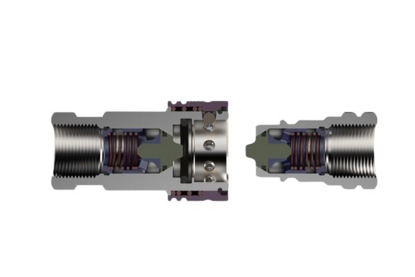
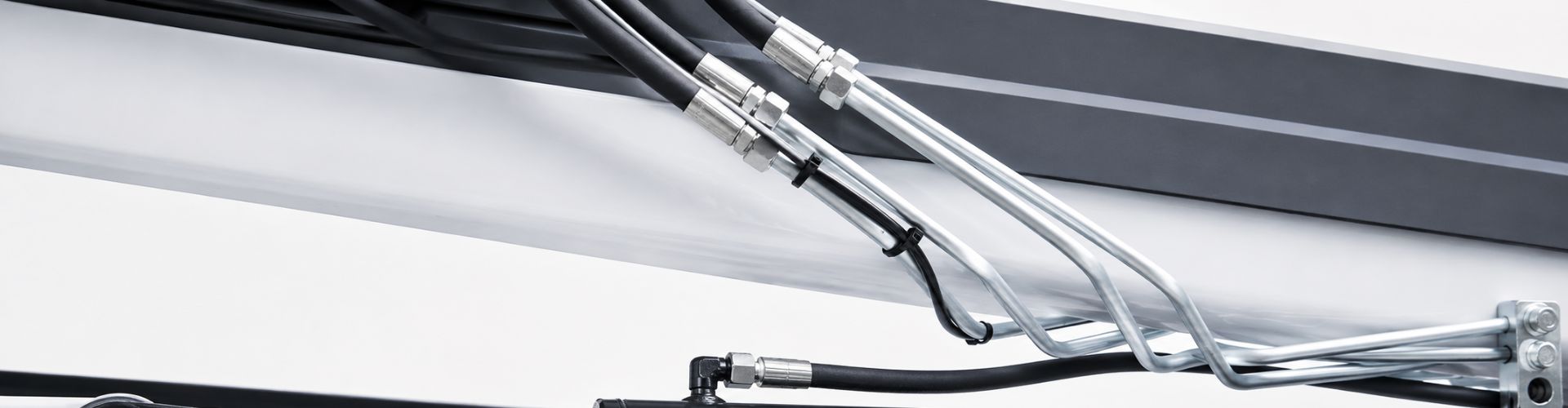
Flat-face hydraulic couplers are specialized connectors used in hydraulic systems to quickly and securely join hoses and components without significant fluid loss. These couplers are designed with a flat sealing surface that minimizes air inclusion and leakage during connection and disconnection. Addressing leaks in flat-face hydraulic couplers is essential for several reasons. Leaks can lead to significant risks and damages, including hydraulic fluid loss, which can cause environmental hazards and increase operational costs. Moreover, leaking couplers can compromise the performance and efficiency of the hydraulic system, leading to reduced pressure, inconsistent operation, and potential failure of machinery.

ISO16028 Flat Face Hydraulic Couplers

Identifying the Problem

Signs of a Leaking Flat Face Hydraulic Coupler

Visible Fluid Leaks

The most apparent sign of a leaking flat face hydraulic coupler is the presence of hydraulic fluid around the coupler or on the ground beneath it. This can manifest as puddles of hydraulic fluid, wet or oily patches on and around the coupler, or streaks of fluid running down the coupler body and nearby components. These visible leaks not only indicate a breach in the sealing system but also pose significant environmental hazards and safety risks. Hydraulic fluid can be slippery, creating slip hazards in the workplace, and potentially harmful if it comes into contact with skin or eyes. Prolonged exposure to hydraulic fluid can lead to dermatitis or other skin conditions. Additionally, spilled hydraulic fluid can contaminate soil and water sources, necessitating thorough cleanup efforts to prevent environmental damage. Regular visual inspections of the hydraulic system and surrounding areas can help in early detection of fluid leaks, allowing for prompt intervention and minimizing the risk of accidents and environmental contamination.

Decreased System Pressure

A significant drop in system pressure is a critical indicator of a hydraulic leak. Hydraulic systems rely on maintaining a consistent pressure to function correctly, and any loss of pressure suggests that fluid is escaping from the system. This pressure drop can affect the performance of hydraulic machinery, leading to slower response times, reduced force output, and inefficient operation. For example, a hydraulic press may not generate enough force to perform its intended function, or a hydraulic lift might struggle to elevate its load. Monitoring system pressure gauges regularly can help identify such leaks early on. If the pressure drops below the expected range, it’s essential to inspect the couplers and other components for potential leaks. In more advanced systems, pressure sensors and diagnostic software can provide real-time alerts and data logging, making it easier to track pressure changes and identify leaks quickly. Addressing pressure drops promptly helps maintain the efficiency and effectiveness of hydraulic systems, reducing downtime and preventing further damage to components.

contamination quick Coupling

Unusual Noises or Vibrations

Unusual noises or vibrations in the hydraulic system can also signal a leaking coupler. When hydraulic fluid escapes from the system, air can enter the hydraulic lines, causing cavitation or aeration. Cavitation occurs when air bubbles form and collapse within the fluid, resulting in noises such as whining, hissing, or knocking sounds, which are not typical during normal operation. These sounds indicate that the hydraulic fluid is not flowing smoothly through the system, leading to erratic performance. Additionally, vibrations may become more pronounced due to the inconsistent fluid flow and the presence of air bubbles in the hydraulic lines. These noises and vibrations can lead to further mechanical issues if not addressed promptly, as they can cause additional wear and tear on the hydraulic components. For instance, cavitation can damage pump impellers and other moving parts, while vibrations can loosen fittings and connections, exacerbating the leak. Using acoustic emission testing or vibration analysis tools can help diagnose the source of these issues, enabling targeted repairs and maintenance to restore smooth and efficient operation.

Identifying the Problem

Wear and Tear Over Time

One of the most common causes of leaks in flat face hydraulic couplers is wear and tear over time. Hydraulic systems are subjected to high pressures and frequent use, which gradually degrade the materials of the couplers. Metal surfaces can become scratched or worn, leading to an imperfect seal. The constant pressure fluctuations and mechanical stresses cause components to fatigue and fail. This natural degradation process can be exacerbated by environmental factors such as exposure to harsh chemicals, extreme temperatures, and abrasive particles.

Improper Installation

Improper installation is another frequent cause of leaks in flat-faced hydraulic couplers. When couplers are not installed correctly, it can lead to misalignments or inadequate sealing. Over-tightening can damage threads or seals, while under-tightening can result in loose connections that allow fluid to escape. Misalignment during installation can create uneven pressure distribution, leading to gaps and potential leak points. Additionally, using the wrong type of coupler or failing to follow manufacturer guidelines during installation can also contribute to leaks.

Contamination and Debris

Contamination and debris can significantly impact the integrity of flat face hydraulic couplers and lead to leaks. Hydraulic systems operate in environments where dirt, dust, and other particles can easily enter the system. When contaminants get lodged in the coupler, they can scratch or damage the sealing surfaces, creating pathways for fluid to leak. Debris can also interfere with the proper functioning of seals and O-rings, causing them to fail prematurely.

Damaged Seals or O-Rings

Damaged seals or O-rings are a typical cause of leaks in flat face hydraulic couplers. These components are crucial for maintaining a secure and leak-proof connection within the hydraulic system. Over time, seals and O-rings can degrade due to exposure to high pressures, temperatures, and hydraulic fluid chemicals. They may become brittle, cracked, or worn out, losing their ability to form a tight seal.

Step-by-Step Guide to Fixing Leaks

Safety Precautions

Depressurize the Hydraulic System

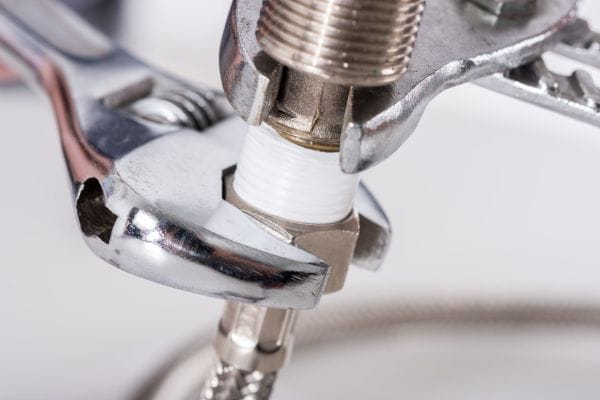
Before starting any repair work on a hydraulic system, it is crucial to ensure that the system is completely depressurized. This involves shutting down the hydraulic machinery and releasing any residual pressure in the system. Failure to depressurize can result in sudden releases of hydraulic fluid, which can cause serious injuries or damage to equipment. Use pressure gauges to verify that the system pressure is at zero before proceeding. Additionally, consult the machinery’s operation manual for specific depressurization procedures.

Ensure a Clean Working Environment

Working in a clean environment is essential to prevent contamination of hydraulic components. Contaminants such as dirt, dust, and debris can compromise the integrity of hydraulic seals and other components, leading to further leaks and system failures. Set up a clean workspace with minimal exposure to contaminants. Use clean tools and materials, and consider laying down clean mats or protective coverings to catch any dislodged debris during the repair process.

Inspecting the Coupler

Visual Inspection for Obvious Damage

Begin by visually inspecting the coupler for any obvious signs of damage. Look for cracks, dents, or deformities on the coupler surfaces and connections. Check for any signs of wear or abrasion that could compromise the seal. Pay close attention to the areas where the coupler connects to other hydraulic components, as these points are prone to damage from physical stress or improper handling.

Checking the Condition of Seals and O-rings

Seals and O-rings are critical components in preventing leaks. Inspect these parts for signs of wear, such as cracks, tears, or brittleness. Check for any deformation or flattening that could affect their ability to form a tight seal. If seals or O-rings appear damaged, they will need to be replaced to restore the coupler’s integrity. Use a magnifying glass or inspection light to get a detailed view of these small components.

Cleaning the Coupler

Removing Debris and Contaminants

Once the inspection is complete, proceed with cleaning the coupler. Use brushes and cleaning agents to remove any dirt and debris from the coupler surfaces. Pay particular attention to the sealing surfaces, as even small particles can prevent a proper seal. Ensure that all contaminants are thoroughly removed to avoid future leaks.

Using Appropriate Cleaning Agents

Choose cleaning agents that are suitable for hydraulic components. Avoid using harsh chemicals that could damage the metal surfaces or the seals. Mild detergents or specialized hydraulic component cleaners are recommended. Rinse the components with clean water if necessary and dry them completely before proceeding with reassembly.

Replacing Damaged Parts

Selecting the Correct Seal Kits and O-rings

Use manufacturer-recommended replacement parts to ensure proper fit and function. Refer to the equipment manual or consult with the manufacturer to obtain the correct seal kits and O-rings for your specific coupler model. Using the wrong parts can lead to improper sealing and further leaks.

Proper Installation Techniques

Follow proper techniques to install seals and O-rings. Ensure they are correctly positioned and seated in their grooves. Apply a thin layer of hydraulic fluid or assembly lubricant to the seals and O-rings to facilitate installation and prevent damage. Use appropriate tools to avoid overstretching or damaging the seals during installation.

Flat Face Hydraulic Coupler install

Reassembling the Coupler

Ensuring All Components are Securely Fitted

Make sure all parts are correctly reassembled according to the manufacturer’s specifications. Align all components properly to ensure a secure fit. Tighten connections hand-tight first to ensure proper alignment before using tools.

Applying the Correct Torque Settings

Use a torque wrench to apply the correct amount of torque to ensure a secure and leak-free connection. Refer to the manufacturer’s specifications for the appropriate torque settings for each connection. Over-tightening can damage threads and seals, while under-tightening can lead to leaks.

Testing for Leaks

Repressurizing the System

Once reassembled, repressurize the hydraulic system to check for leaks. Gradually increase the system pressure while monitoring for any signs of leaks. This helps prevent sudden pressure spikes that could cause new leaks or damage.

Monitoring for Signs of New Leaks

Observe the coupler for any signs of new leaks during and after repressurization. Look for any fluid seepage, drops in system pressure, or unusual noises. Conduct a thorough inspection around the coupler and other components to ensure the repair was successful. If any leaks are detected, repeat the inspection and repair process as necessary.

By following these detailed steps, you can effectively diagnose and fix leaks in flat face hydraulic couplers, ensuring the continued performance and reliability of your hydraulic systems. Regular maintenance and proper handling are key to preventing leaks and maintaining optimal performance.

Preventative Maintenance Tips

Scheduled Checks for Wear and Damage

Implementing a regular inspection schedule is essential for maintaining the integrity of hydraulic systems. These scheduled checks should be designed to thoroughly examine the hydraulic couplers for any signs of wear and damage. This includes looking for scratches, dents, cracks, or deformities on the metal surfaces, as well as checking the seals and O-rings for signs of wear, brittleness, or damage. By identifying and addressing these issues early, you can prevent minor problems from escalating into major failures that could lead to costly repairs and downtime. Utilizing detailed checklists and logging inspection results can help ensure that no potential issues are overlooked during these routine checks.

Routine Cleaning and Lubrication

Keeping hydraulic couplers clean and well-lubricated is vital for preventing contamination and wear. Contaminants such as dirt, dust, and other particles can damage the sealing surfaces and lead to leaks. Routine cleaning should involve using appropriate cleaning agents to remove any buildup of debris or grime on the couplers. Additionally, regular lubrication of the moving parts and seals can help reduce friction, prevent wear, and ensure smooth operation. It’s important to use the correct type of lubricant specified by the manufacturer to avoid compatibility issues that could degrade the seals and other components. Establishing a consistent cleaning and lubrication routine can significantly extend the lifespan of the couplers and enhance the overall performance of the hydraulic system.

Conclusion

Leaks can lead to decreased system pressure, compromised performance, and potential environmental hazards. To effectively fix and prevent leaks, it is essential to follow a systematic approach: identify the problem through visual inspections and monitoring system performance; clean and maintain the couplers to prevent contamination; replace worn or damaged seals and O-rings using proper installation techniques; and ensure all components are compatible and installed according to manufacturer guidelines. By adhering to these practices, you can enhance the durability and reliability of your hydraulic equipment, reducing downtime and operational costs.

FAQ

Flat face hydraulic couplers are connectors used in hydraulic systems to join two hydraulic lines, providing a leak-free connection and minimizing fluid loss during connection and disconnection.

Common signs include visible hydraulic fluid leaks around the coupler or on the ground, decreased system pressure, and unusual noises or vibrations in the hydraulic system.

Prevent leaks by performing regular inspections for wear and damage, keeping the couplers clean and well-lubricated, following proper installation practices, and using compatible components.

If a leak is detected, depressurize the hydraulic system, inspect the coupler for damage, clean the components, replace any worn or damaged seals and O-rings, and reassemble the coupler according to manufacturer specifications.

Hydraulic couplers should be inspected regularly as part of a scheduled maintenance program. The frequency of inspections depends on the usage and operating conditions of the hydraulic system.

Common causes of leaks include wear and tear over time, improper installation, contamination and debris, and damaged seals or O-rings. Regular maintenance and proper handling can help mitigate these issues.

Contact Topa

Have a question or suggestion? Fill out the form below to get in touch with one of our experts.

Quick Connect Sizes Explained A Comprehensive Comparison

Quick Connect Sizes Explained: A Comprehensive Comparison

Quick Connect Sizes Explained: A Comprehensive Comparison

Introduction

Quick-connect fittings are essential components used in a wide range of industries, including hydraulics, plumbing, and automotive sectors. These fittings are designed to create secure and efficient connections without the need for tools, enabling quick and easy assembly and disassembly. Their versatility and convenience make them indispensable for applications where speed and reliability are crucial. Quick connect fittings come in various sizes and configurations, each tailored to specific needs and systems. Understanding these sizes is paramount to ensuring compatibility, preventing leaks, and optimizing system performance.

What Are Quick Connect Fittings?

Quick connect fittings, also known as quick disconnects or quick release couplings, are specialized connectors designed to join or separate fluid lines rapidly and effortlessly. These fittings consist of two main components: a plug (or male part) and a socket (or female part). When these two components are pushed together, they form a secure and leak-proof connection. The release mechanism allows for quick disconnection without the need for tools, making them highly efficient for applications where frequent assembly and disassembly are required.

Common Uses in Various Industries

Hydraulic Systems

  • Used to quickly connect/disconnect hoses and components.
  • Helps reduce downtime during maintenance or equipment changes.

Plumbing

  • Commonly used for connecting pipes, faucets, and appliances.
  • Speeds up installation and makes repairs more convenient.

Automotive Industry

  • Found in fuel lines, brake systems, and A/C units.
  • Offers fast, leak-proof connections essential for safety and efficiency

Benefits of Using Quick Connect Fittings

Time and Labor Savings

  • Instant connection and disconnection reduces setup and maintenance time.
  • No need for wrenches or sealants during installation.
  • Ideal for frequent assembly/disassembly tasks.

Ease of Use

  • Requires minimal training or technical expertise.
  • Simplifies field operations and emergency servicing.
  • Suitable for both professionals and non-specialists.

Reliable, Leak-Proof Connections

  • Engineered for secure sealing under pressure.
  • Maintains fluid or gas system integrity.
  • Reduces the risk of contamination or system failure.

Enhanced Safety and Efficiency

  • Prevents accidental disconnection or leakage.
  • Supports safe handling of high-pressure or hazardous fluids.
  • Contributes to consistent system performance.

Cost Effectiveness

  • Reduces equipment downtime and labor costs.
  • Low maintenance requirements due to durable design.
  • Fewer replacements = long-term savings.
Hydraulic Quick coupler Manufacturer in China Topa

Types of Quick Connect Fittings

Push-to-Connect Fittings

Push-to-connect fittings, also known as push-fit fittings, are designed for simplicity and ease of use. These fittings feature a collet with stainless steel teeth that grip the pipe when it is inserted into the fitting. Inside, an O-ring ensures a watertight seal. To connect, simply push the pipe into the fitting until it clicks into place. Disconnection is equally straightforward, usually requiring the user to depress a release ring while pulling the pipe out.

Threaded Quick Connect Fittings

Threaded quick connect fittings utilize a threaded connection to secure the fitting to the pipe or hose. These fittings can be male or female and come in various thread standards such as NPT (National Pipe Thread), BSP (British Standard Pipe), and metric threads. The threaded design ensures a robust and secure connection capable of withstanding high pressures and stresses. Installation requires screwing the fitting onto the corresponding threaded component, often using thread sealant or tape to ensure a leak-proof connection.

Barbed Quick Connect Fittings

Barbed quick connect fittings are designed to connect flexible hoses to rigid pipes or other fittings. These fittings have barbs or ridges that grip the inside of the hose, providing a secure connection. The hose is typically secured onto the barbed fitting using a hose clamp for added security. Barbed fittings are commonly used in low-pressure applications such as irrigation systems, automotive vacuum lines, and various fluid transfer applications. Their design allows for a secure connection even when the hose expands and contracts due to changes in pressure or temperature.

Importance of Correct Sizing  

Ensuring Compatibility and Preventing Leaks

Selecting the correct size for quick connect fittings is critical to ensuring compatibility between different components within a fluid or gas system. Properly sized fittings form tight seals, which are essential for preventing leaks. Leaks can lead to fluid loss, which not only reduces the efficiency of the system but also poses potential safety hazards, especially in systems handling hazardous or pressurized fluids. A fitting that is too small or too large can result in poor connections, leading to frequent maintenance issues and potential system failures. Ensuring that the fittings are appropriately sized eliminates these risks and enhances the overall reliability of the system.

Impact on Performance and Safety

The performance and safety of any system that uses quick-connect fittings heavily depend on correct sizing. Properly sized fittings ensure that the flow rate is maintained as per the design specifications, which is crucial for the optimal functioning of the system. For instance, in hydraulic systems, an incorrect fitting size can cause significant pressure drops, leading to inefficient performance and increased wear and tear on system components. Additionally, in safety-critical applications, such as in medical or aerospace industries, the consequences of using incorrectly sized fittings can be catastrophic, potentially leading to system failures and endangering lives. Hence, correct sizing is not just a matter of efficiency but also of ensuring the highest safety standards.

Cost Implications of Incorrect Sizing

Using incorrectly sized quick connect fittings can lead to significant cost implications. Leaks caused by improper fitting sizes result in the wastage of fluids and increased maintenance costs due to frequent repairs and replacements. The downtime associated with fixing these issues can further add to operational costs, as it impacts productivity and efficiency. Moreover, the wear and damage caused to other system components by improper sizing can lead to premature failures, necessitating costly replacements and repairs.

Measurement Standards and Systems

Imperial vs Metric Systems

When dealing with quick connect fittings, it is crucial to understand the two main measurement systems used globally: the Imperial system and the Metric system. The Imperial system, primarily used in the United States, measures dimensions in inches, feet, and pounds. Conversely, the Metric system, used by most other countries, measures in millimeters, centimeters, meters, and kilograms. Understanding these systems is essential for ensuring compatibility and accuracy when selecting and installing quick-connect fittings.

measure hydraulic quick connect fittings Topa

Common Measurement Standards

Several standardized measurement systems are used for quick connect fittings, each with unique characteristics and applications:

  • NPT (National Pipe Thread): This is a U.S. standard for tapered threads used on threaded pipes and fittings. NPT threads are angled at 60 degrees and provide a tight, leak-proof seal. They are commonly used in the plumbing and hydraulic industries.
  • BSP (British Standard Pipe): BSP is a standard used internationally, especially in the UK and former British territories. It includes BSPT (tapered) and BSPP (parallel) threads. BSP threads have a 55-degree angle and are widely used in plumbing and industrial applications.
  • JIC (Joint Industry Council): JIC fittings use a 37-degree flare to form a metal-to-metal seal, providing high pressure and vibration resistance. They are commonly used in hydraulic systems, especially in the automotive and aerospace industries.
  • SAE (Society of Automotive Engineers): SAE fittings, similar to JIC fittings, often use a 45-degree flare. They are standard in automotive and refrigeration applications.

How to Measure Quick Connect Sizes Accurately

Accurately measuring quick connect sizes is critical for ensuring a proper fit and function within your systems. Incorrect measurements can lead to leaks, system failures, and increased maintenance costs. Here are the detailed steps to measure these sizes accurately:

Identify the Type of Fitting

The first step in measuring quick connect sizes is to determine the type of fitting you are dealing with. Quick-connect fittings can be push-to-connect, threaded, or barbed.

Measure the Diameter

The next step is to measure the diameter of the fitting. This measurement varies depending on the type of fitting:

  • Threaded Fittings: Use a pair of calipers to measure the outside diameter (OD) of the male threads or the inside diameter (ID) of the female threads. This ensures that you get an accurate measurement of the thread size.
  • Push-to-Connect and Barbed Fittings: Measure the OD of the part that connects to the hose or pipe. For barbed fittings, this means measuring the widest part of the barb.

Accurate diameter measurement is crucial for ensuring compatibility with hoses, pipes, and other system components.

Determine the Thread Pitch

For threaded fittings, the thread pitch is a critical measurement. The thread pitch is the distance between threads and is measured in threads per inch (TPI) for Imperial systems or in millimeters between threads for Metric systems:

  • Use a thread pitch gauge to measure the thread pitch. This tool has multiple blades, each marked with different pitches. Match the threads of your fitting with the appropriate blade on the gauge.
  • Ensure that the gauge fits snugly into the threads without any gaps to get an accurate measurement.

Consult Standard Charts

Once you have your diameter and thread pitch measurements, consult standard charts to correlate these measurements with the correct fitting size and type. These charts are often available from manufacturers and industry organizations:

  • Find the section of the chart that corresponds to the type of fitting you are measuring.
  • Locate your diameter and thread pitch measurements on the chart to determine the correct size.
  • These charts are invaluable for ensuring that you select the right fitting size, especially when dealing with various thread standards and measurement systems.

Factors to Consider When Choosing Size

Pressure

The operating pressure of your system is one of the most critical factors when selecting a quick connect fitting. Each fitting is designed to withstand a specific range of pressures. Using a fitting that is not rated for your system’s pressure can lead to catastrophic failures, including bursts, leaks, and safety hazards. It is essential to:

  • Identify Maximum and Minimum Operating Pressure: Understand both the maximum and minimum operating pressures your system will encounter. This ensures that the fitting can handle extreme conditions without compromising safety or performance.
  • Check Pressure Ratings: Manufacturers provide pressure ratings for their fittings. Compare these ratings to your system requirements to ensure compatibility. High-pressure systems may require fittings made from more robust materials, such as stainless steel, to prevent deformation or failure.

Flow Rate

The flow rate of your system dictates how much fluid or gas moves through the fitting over a given period. The internal diameter of the fitting plays a significant role in determining the flow rate. To ensure optimal system efficiency:

  • Measure Required Flow Rate: Calculate the flow rate needed for your application. This information is crucial for selecting a fitting with an appropriate internal diameter.
  • Consider Pressure Drop: A fitting that is too small for the required flow rate can cause a significant pressure drop, reducing system efficiency and potentially leading to operational issues. Ensure the selected fitting maintains the desired flow rate without causing unnecessary pressure loss.

Application Specifics

Each application has unique requirements that influence the selection of quick connect fittings. Consider the following specifics:

  • Type of Fluid or Gas: Different materials and designs are suited for various fluids and gases. For example, corrosive fluids may require fittings made from corrosion-resistant materials like stainless steel or specialized plastics.
  • Temperature Ranges: High or low temperatures can affect the integrity of the fitting material. Ensure the fitting can withstand the temperature extremes of your application without degrading.
  • Environmental Conditions: Consider the environment where the fitting will be used. Factors such as exposure to chemicals, moisture, UV light, and physical impacts can influence the choice of fitting material and design.
Hydraulic Quick coupler factory Agriculture

Compatibility

Ensuring compatibility with existing system components is crucial for maintaining a leak-proof and secure connection. Compatibility considerations include:

  • Thread Types and Sizes: Different thread standards (e.g., NPT, BSP, JIC, SAE) must match exactly to prevent leaks and ensure a tight seal. Verify the thread type and size of both the fitting and the components it will connect to.
  • Material Compatibility: The material of the fitting should be compatible with the materials of the hoses, pipes, and other fittings in your system to avoid reactions that could weaken connections or cause leaks.
  • System Components: Ensure the selected quick-connect fitting integrates seamlessly with other system components, such as valves, pumps, and filters, to maintain overall system integrity and performance.

By thoroughly considering these factors—pressure, flow rate, application specifics, and compatibility—you can select the right quick connect size for your needs. This careful selection process helps ensure your system operates efficiently, safely, and reliably, minimizing downtime and maintenance costs

Common Mistakes to Avoid

Ignoring Pressure Ratings:

Do not overlook the pressure rating of the fitting. Using a fitting with a lower pressure rating than required can lead to dangerous system failures.

Overlooking Thread Compatibility:

Ensure the thread type and size match exactly with existing system components. Mismatched threads can cause leaks and disconnections.

Incorrect Measurements:

Take accurate measurements using the correct tools, such as calipers and thread pitch gauges. Inaccurate measurements can result in selecting the wrong fitting size.

Neglecting Material Compatibility:

Choose a fitting material that is compatible with the fluid or gas and environmental conditions. Incompatible materials can lead to corrosion, degradation, and system failures.

Conclusion

Understanding the various aspects of quick connect sizes is crucial for ensuring the efficiency, safety, and reliability of any fluid or gas system. Throughout this post, we have explored the definition and types of quick-connect fittings, the importance of correct sizing, and the critical factors to consider when selecting the right size. By accurately measuring fittings and comprehending the different measurement standards, you can prevent leaks, maintain optimal performance, and reduce maintenance costs.

FAQ

Quick connect fittings are connectors designed to join or separate fluid or gas lines quickly and easily without the need for tools. They are commonly used in various industries, including hydraulics, plumbing, and automotive.

To measure a quick connect fitting, use calipers to measure the outside diameter (OD) of male threads or the inside diameter (ID) of female threads. For push-to-connect and barbed fittings, measure the OD of the part that connects to the hose or pipe. Use a thread pitch gauge for threaded fittings to determine the thread pitch.

NPT (National Pipe Thread) and BSP (British Standard Pipe) threads differ in thread angle and pitch. NPT threads have a 60-degree angle and are used mainly in the United States, while BSP threads have a 55-degree angle and are used internationally, especially in the UK and former British territories.

Choosing the correct quick connect size is essential for ensuring compatibility, preventing leaks, and maintaining the system’s performance and safety. Incorrect sizing can lead to fluid loss, pressure drops, and potential system failures.

Yes, quick connect fittings can be used with both liquids and gases. However, it is crucial to choose fittings made from materials compatible with the specific fluid or gas and the application’s pressure and temperature requirements.

Quick connect fittings are made from various materials, including brass, stainless steel, plastic, and aluminum. The choice of material depends on the application’s specific requirements, such as pressure, temperature, and chemical compatibility.

Quick Connect Not Working Discover the Solutions

Quick Connect Not Working? Discover the Solutions

Quick Connect Not Working? Discover the Solutions

Table of Contents

Introduction

Quick connect fittings are essential components in many applications, providing fast, reliable, and leak-free connections in industries ranging from hydraulics to plumbing. However, when these connectors fail, it can lead to significant downtime and costly repairs. In this post, we will delve into the common problems associated with quick connect fittings, offers practical solutions to address these issues and provide preventive measures to ensure your quick connects work seamlessly.

Understanding Quick Connects

Definition and Function

Quick connect fittings are specialized connectors designed to swiftly and securely join hoses, tubes, and pipes in various systems without the need for tools. Their primary function is to enable fast, leak-free connections and disconnections, streamlining the setup and maintenance processes in a wide range of applications. These fittings typically consist of two main components: the plug and the socket, which are designed to snap together easily, creating a tight seal that prevents leaks and ensures reliable operation.

Common Uses

Quick-connect fittings are widely used across numerous industries due to their convenience and efficiency. In hydraulics, they are essential for connecting hydraulic lines, allowing for easy maintenance and rapid equipment changes without system downtime. In plumbing, quick-connect fittings are used for water supply lines, providing reliable and leak-free connections for household and commercial plumbing systems. Additionally, these fittings are prevalent in the automotive industry for fuel and coolant lines, in the medical field for connecting various medical devices, and in industrial applications for air and fluid lines in manufacturing processes.

Types of Quick Connects

Flat quick release hydraulic fitting

There are several types of quick-connect fittings, each designed for specific applications and connection requirements:

Push-to-Connect: These fittings allow for a simple push connection, where the tubing is pushed into the fitting to create a secure and leak-proof connection. They are commonly used in pneumatic and hydraulic systems.

Threaded: Threaded quick-connect fittings feature screw threads on the connectors, providing a robust and reliable connection. They are often used in high-pressure applications where a strong, vibration-resistant connection is necessary.

Cam-Lock: These fittings use cam arms to lock the connection in place, making them ideal for applications that require frequent connection and disconnection, such as in fluid transfer systems.

Collet Connect: These fittings utilize a collet mechanism that grips the tubing when inserted, ensuring a secure and tight connection. They are widely used in water and beverage dispensing systems.

Bayonet: Bayonet quick connects use a twist-and-lock mechanism, providing a secure connection that is resistant to accidental disconnection. They are commonly used in electrical and electronic applications.

Common Issues with Quick Connects

Leakage Problems

Causes:

Damaged O-rings: O-rings play a critical role in maintaining a tight seal within quick connect fittings. Over time, these O-rings can become cracked, brittle, or flattened due to regular use, exposure to extreme temperatures, or contact with incompatible fluids. When O-rings are compromised, they can no longer provide an effective seal, leading to leaks.

Improper Installation: Proper installation of quick connect fittings is crucial for ensuring a leak-free connection. If the fittings are not seated correctly or fully engaged, gaps can form where leaks can occur. This can happen if the fittings are not aligned properly or if insufficient force is applied during the connection process.

Worn Seals: Similar to O-rings, the seals within quick connect fittings can degrade over time. Regular wear and tear, exposure to harsh conditions, and the natural aging of materials can cause seals to lose their elasticity and effectiveness. As seals wear out, they fail to maintain a tight connection, resulting in leaks.

Symptoms:

Visible Drips: One of the most obvious signs of a leak in a quick-connect system is the presence of liquid or air leaking around the connection point. This can range from a slow, steady drip to a more significant flow, depending on the severity of the leak.

Pressure Drops: In hydraulic or pneumatic systems, leaks can lead to noticeable drops in pressure. This can affect the performance of the entire system, causing machinery to operate inefficiently or even fail.

Noise: Leaks can also produce audible signs, such as hissing or bubbling sounds. These noises indicate that air or fluid is escaping from the connection point, which can help pinpoint the location of the leak.

leaky quick coupling

Connection Failures

Causes:

Misalignment: Quick-connect fittings rely on precise alignment between the plug and socket to create a secure connection. Misalignment can prevent the components from engaging correctly, leading to an insecure connection that can easily come apart.

Insufficient Force: Connecting quick-connect fittings often requires a specific amount of force to ensure they lock together properly. If insufficient force is applied, the connection may be weak or partial, increasing the risk of failure under pressure.

Worn Components: Over time, the components of quick-connect fittings can wear out. This wear can make it difficult to secure a proper connection, as the parts may not fit together as tightly as they should. Wear can be exacerbated by frequent use, mechanical stress, and environmental factors.

Symptoms:

Loose Fittings: A telltale sign of connection failure is fittings that can be easily pulled apart without using the intended release mechanism. This indicates that the connection is not secure and is prone to failure.

Intermittent Function: Systems with poor connections may work sporadically, functioning correctly one moment and failing the next. This inconsistency can be frustrating and lead to unreliable system performance.

Wear and Tear

Causes:

Frequent Use: Quick-connect fittings are designed for repeated connections and disconnections. However, regular use can lead to wear on the components, such as the locking mechanisms, seals, and the surfaces where the fittings meet.

Environmental Factors: Exposure to harsh environments can accelerate wear and tear on quick-connect fittings. Extreme temperatures, corrosive chemicals, and moisture can all contribute to the degradation of materials over time.

Mechanical Stress: Vibration and movement in the system can put additional stress on quick-connect fittings. This mechanical stress can lead to fatigue and eventual failure of the components.

Symptoms:

Cracks and Deformities: Visual inspections can reveal signs of wear and tear, such as cracks, deformities, or other damage on the fittings. These signs indicate that the fittings are no longer in optimal condition and may be prone to failure.

Decreased Performance: As quick connect fittings wear out, the overall efficiency and performance of the system can decline. This can result in slower operation, reduced pressure, or other issues that compromise the system’s effectiveness.

Compatibility Issues

Causes:

Mismatched Sizes: Using quick connect fittings that are not the correct size for the application can lead to problems. Fittings that are too large or too small will not create a secure connection, leading to leaks and other issues.

Different Standards: Quick connect fittings come in various standards, such as metric and imperial. Mixing components that adhere to different standards can result in incompatibility, as the parts may not fit together correctly.

Material Incompatibility: Different materials can react negatively with each other or with the fluids or gases being transferred. Using materials that are not compatible can lead to corrosion, chemical reactions, and other problems that compromise the integrity of the quick-connect fittings.

Symptoms:

Difficulty Connecting: Incompatibility can make it difficult or impossible to fit components together. This can be a sign that the sizes or standards of the fittings do not match.

Leaks and Failures: Incompatible components may not create a proper seal, leading to leaks and potential system failures.

Corrosion and Damage: Accelerated wear or chemical reactions can cause damage to the fittings, making them less effective and more prone to failure.

Debris and Contamination

contamination quick Coupling

Causes:

Foreign Materials: Dirt, dust, and other debris can enter the quick-connect system, especially during connections and disconnections. These foreign materials can obstruct the internal components and interfere with the connection.

Fluid Contamination: Impurities in the fluid or gas being transferred can introduce contaminants into the quick-connect system. These impurities can cause abrasion and damage to the internal components.

Environmental Exposure: External contaminants can enter the system during connections or disconnections, particularly in dirty or dusty environments. This exposure can lead to debris accumulation and system contamination.

Symptoms:

Blockages: Debris and contamination can reduce or block the flow through the quick-connect fittings. This can lead to decreased system performance and potential failures.

Abrasion and Damage: Contaminants can cause wear and tear on the internal components, leading to abrasion and damage. This can compromise the integrity of the fittings and lead to leaks or failures.

Seal Compromise: Debris can interfere with the ability of seals to maintain a tight connection. This can result in leaks and other issues that affect the performance of the quick-connect fittings.

Understanding these common issues can help in diagnosing and addressing problems with quick connect fittings, ensuring they perform reliably and efficiently in various applications. By identifying the causes and symptoms of these issues, users can take proactive steps to maintain their quick-connect systems and prevent future problems.

Solutions for Quick Connect Not Working

Fixing Leakage Problems

Step-by-Step Guide to Fixing Common Leak Issues

Identify the Source: Locate the exact point where the leak is occurring.

Inspect O-rings and Seals: Check for visible damage, wear, or displacement.

Clean the Fittings: Remove any debris or contaminants that might interfere with the seal.

Replace Damaged Parts: Replace any worn or damaged O-rings, seals, or fittings.

Reassemble and Test: Reconnect the fittings and test the system for leaks.

Replacing O-rings

Identify Faulty O-rings: Look for signs of cracking, brittleness, or flattening.

Remove the Old O-ring: Use a pick or a similar tool to carefully remove the damaged O-ring.

Select the Correct Replacement: Ensure the new O-ring matches the size and material specifications.

Install the New O-ring: Lubricate the new O-ring if necessary and place it in the correct position.

Test the Connection: Reconnect the fittings and test for leaks.

Tightening Connections

Proper Techniques for Securing Connections:

Hand-Tighten First: Begin by hand-tightening the connection to ensure alignment.

Use the Right Tools: Employ wrenches or pliers specifically designed for the fittings.

Avoid Over-Tightening: Apply just enough force to secure the connection without damaging the fittings.

quick coupler O-ring seal fix

Resolving Connection Failures

Proper Installation Techniques

Align Components Correctly: Ensure the plug and socket are properly aligned before connecting.

Apply Adequate Force: Push or screw the fittings together with sufficient force to secure the connection.

Listen for Clicks or Feel for Resistance: Many quick connects have audible or tactile cues indicating a secure connection.

Using the Right Tools

Torque Wrenches: Use torque wrenches to apply the correct amount of force.

Specialized Pliers: Utilize pliers designed for quick-connect fittings to avoid damage.

Handling Wear and Tear

Regular Inspections

Schedule Routine Checks: Inspect the fittings regularly for signs of wear and tear.

Look for Cracks and Deformities: Pay attention to any visible damage on the fittings.

Test for Performance: Periodically test the system to ensure it is functioning correctly.

Replacement Protocols

When and How to Replace Worn-Out Parts:

Monitor Usage Frequency: Replace parts more frequently if the system is used heavily.

Replace at Signs of Wear: Do not wait for a complete failure; replace parts showing signs of wear.

Keep Spare Parts: Maintain an inventory of critical replacement parts for quick swaps.

Addressing Compatibility Issues

Selecting the Right Components

Match Sizes and Standards: Ensure all fittings adhere to the same size and standard (e.g., metric or imperial).

Check Material Compatibility: Use materials that are compatible with the fluids or gases being transferred.

Consult Manufacturer Guidelines: Follow the manufacturer’s recommendations for compatible components.

Consulting Manufacturer Guidelines

Technical Support: Reach out to the manufacturer’s technical support for advice on compatibility.

Product Manuals: Refer to product manuals and specification sheets for detailed compatibility information.

Compatibility Charts: Use manufacturer-provided charts to match compatible components.

Preventing Debris and Contamination

Keeping the System Clean

Regular Cleaning: Clean the quick connect fittings and surrounding areas regularly.

Use Appropriate Cleaning Agents: Select cleaning agents that are safe for the materials of the fittings.

Flush the System: Periodically flush the system to remove any built-up debris or contaminants.

Using Filters and Protectors

Install Filters: Use filters to catch debris before it enters the quick connect system.

Use Dust Caps: Cover unused quick connect fittings with dust caps to prevent contamination.

Seal Exposed Ends: When disconnecting, seal the exposed ends to keep contaminants out.

Conclusion

In summary, addressing common issues with quick connect fittings involves understanding the causes of leakage, connection failures, wear and tear, compatibility issues, and debris contamination. We have provided detailed solutions for fixing leaks by replacing damaged O-rings and ensuring proper installation techniques, as well as tips for maintaining and prolonging the life of your quick-connect fittings through regular inspections and using the right tools. As a final tip, always adhere to manufacturer guidelines and consult technical support when in doubt.

FAQ

First, inspect the fitting for any visible damage or worn O-rings. Replace any damaged parts, ensure the fitting is properly seated, and test the connection again.

It’s recommended to perform routine inspections every few months, especially if the fittings are used frequently or in harsh environments. Regular checks can help identify wear and tear early.

No, it’s important to use O-rings that match the size and material specifications of your quick connect fittings to ensure a proper seal and compatibility with the system’s fluids or gases.

Tools like torque wrenches, specialized pliers, and alignment tools can help ensure a secure and proper connection without damaging the fittings.

Use filters to catch debris before it enters the system, and apply dust caps on unused fittings. Regular cleaning and flushing of the system can also help maintain cleanliness.

Look for visible cracks, deformities, or any signs of wear and tear. If you notice frequent leaks, connection failures, or reduced system performance, it may be time to replace the fitting.

Contact Topa

Have a question or suggestion? Fill out the form below to get in touch with one of our experts.

Hydraulic Quick Coupler Identification Key Tips and Tricks

Hydraulic Quick Coupler Identification: Key Tips and Tricks

Hydraulic Quick Coupler Identification: Key Tips and Tricks

Introduction

Proper identification of hydraulic quick couplers is crucial to avoid mismatches that can lead to equipment failure or damage. Ensuring compatibility between couplers and their respective hydraulic systems enhances overall efficiency and safety. Accurate identification helps in selecting the right coupler for specific applications, preventing potential leaks, and maintaining optimal hydraulic pressure. This not only improves the longevity of the equipment but also ensures smooth and reliable operation, ultimately contributing to the productivity and safety of the work environment.

Understanding Hydraulic Quick Couplers

Hydraulic quick couplers are mechanical devices used to rapidly connect and disconnect hydraulic lines without the need for tools or excessive manual labor. They facilitate quick and efficient coupling of hoses, pipes, or tubing in hydraulic systems, enabling fluid transfer under pressure. These couplers typically feature a male and female component with complementary mechanisms that lock together securely to create a leak-free seal.

Types of Hydraulic Quick Couplers

Threaded Couplers

Threaded couplers are a fundamental type of hydraulic quick coupler known for their robustness and reliability. These couplers feature threaded connections that ensure a secure fit, making them ideal for applications requiring high-pressure fluid transfer. Identification of threaded couplers involves understanding various thread types such as BSP (British Standard Pipe), NPT (National Pipe Thread), or metric threads, each with specific sizing and compatibility considerations. Materials commonly used include stainless steel for durability and resistance to corrosion, essential in industries like construction, agriculture, and manufacturing where reliability under challenging conditions is paramount.

Push-to-Connect Couplers

Push-to-connect couplers are designed for quick and easy assembly without the need for tools or threading. They operate by simply pushing the coupling into the counterpart until it clicks into place, creating a leak-proof seal. Identification is straightforward due to their distinctive design featuring release buttons or collars for disconnecting. Pros of push-to-connect couplers include rapid installation, and reduced downtime during maintenance, while cons include potential limitations in high-pressure applications compared to threaded or flat-face couplers. They are popular in automotive, pneumatic tools, and light industrial applications for their convenience and ease of use.

Flat Face Couplers

QKPT Quick coupler Topa

Flat face couplers are recognized for their spill-free connection, making them suitable for applications where cleanliness and environmental concerns are critical. Their design prevents fluid loss during connection and disconnection, enhancing safety and efficiency. Identification methods typically involve visual inspection of the flat faces, which mate flush to prevent contamination and ensure a tight seal. Materials like carbon steel or stainless steel are common, ensuring compatibility with hydraulic fluids and resistance to wear. Ideal applications include construction equipment, forestry machinery, and hydraulic systems operating in sensitive environments where fluid leakage could pose risks.

Twist Lock Couplers

Twist lock couplers feature a twist-and-lock mechanism that secures the connection with a simple twist, ensuring a tight and reliable seal. This type of coupler is favored for its ease of use and resistance to accidental disconnection, especially in applications where vibrations or movement may occur. Identification is straightforward due to the distinctive twisting action required for connection and disconnection. Twist lock couplers are widely used in agricultural machinery, mining equipment, and hydraulic attachments on construction sites, where quick coupling and durability are essential for productivity and safety.

Ball Lock Couplers

Ball lock couplers utilize a ball-bearing mechanism to secure the connection, offering a reliable and leak-free seal. They are designed for high-pressure applications and provide excellent resistance to vibration and shock. Identification involves checking for the ball-locking mechanism and ensuring proper alignment for connection. Ball-lock couplers are commonly used in hydraulic systems for heavy machinery, hydraulic tools, and industrial equipment where dependable performance under pressure is critical.

KPC Quick coupler

Bayonet Couplers

Bayonet couplers feature a bayonet-style locking mechanism that ensures a secure and quick connection. They are known for their ease of use and reliability, often used in applications requiring frequent coupling and decoupling. Identification is typically based on the number and alignment of bayonet pins, ensuring proper engagement for a tight seal. These couplers find applications in hydraulic systems for medical devices, aerospace, and automotive industries where precision and speed of connection are important.

Cam and Groove Couplers

Cam and groove couplers, also known as camlock fittings, are characterized by their simple and effective locking mechanism using cams and grooves. They are quick to connect and disconnect, making them ideal for applications requiring frequent changes or temporary connections. Identification is based on the size and type of cam arms (A, B, C, D, etc.) which dictate compatibility between couplers. These couplers are widely used in industries such as agriculture, chemical processing, and petroleum where rapid assembly and disassembly are essential.

Factors Influencing Coupler Selection

Hydraulic couplers play a crucial role in the efficiency, safety, and functionality of hydraulic systems. Several key factors influence the selection of the appropriate coupler:

Hydraulic System Requirements

Hydraulic systems vary widely in terms of pressure ratings, flow rates, and fluid compatibility. Couplers must be selected based on these specifications to ensure optimal performance and reliability. High-pressure hydraulic systems, for instance, require couplers designed to withstand the pressure without leaking or failing, while systems with varying flow rates may benefit from quick-connect couplers that facilitate rapid coupling and decoupling.

Environmental Considerations

Environmental factors such as temperature extremes, exposure to chemicals or corrosive substances, and outdoor conditions significantly impact coupler selection. Couplers made from materials like stainless steel or brass are preferred in corrosive environments to prevent degradation and maintain performance over time. Similarly, temperature-sensitive applications may require couplers capable of withstanding extreme heat or cold without compromising functionality.

Compatibility with Hoses and Fittings

Coupler selection must align with the types of hoses and fittings used within the hydraulic system. Compatibility ensures a secure and leak-free connection, reducing the risk of fluid loss or system damage. Factors such as thread type (e.g., BSP, NPT), hose diameter, and fitting design (e.g., push-to-connect, flat face) should be carefully matched to ensure proper sealing and operational efficiency.

Impact on System Efficiency and Safety

The choice of hydraulic coupler directly influences system efficiency and safety. Efficient couplers minimize fluid loss during connection and disconnection, reducing downtime and operational costs. Couplers that provide a secure, leak-free seal enhance system reliability, preventing potential hazards such as fluid spills or contamination. Safety features such as locking mechanisms or pressure relief valves further contribute to safe operation, particularly in high-pressure or critical applications.

By considering these factors—hydraulic system requirements, environmental conditions, compatibility with hoses and fittings, and impact on system efficiency and safety—engineers and operators can make informed decisions when selecting hydraulic couplers. This approach ensures optimal performance, longevity, and safety of hydraulic systems across various industrial applications.

Identification Methods and Tips

Visual Inspection

Visual inspection is a primary method for identifying hydraulic couplers, focusing on distinct visual features and differences between similar types:

Key Visual Features to Look For:

Visual inspection involves examining specific features that distinguish one type of coupler from another:

Design and Shape: Different types of couplers have unique shapes and designs. For example, threaded couplers have visible threads on both the male and female ends, while push-to-connect couplers feature a cylindrical body with release buttons or collars.

Color and Material: Couplers may be color-coded or made from different materials such as stainless steel, brass, or carbon steel. These materials offer clues about durability, compatibility with fluids, and environmental resistance.

Size and Dimensions: Checking the size and dimensions of couplers is crucial for compatibility with hoses and fittings. This includes diameter measurements, overall length, and the shape of sealing surfaces.

Differences Between Similar Couplers:

Identifying subtle differences between similar couplers requires attention to detail:

Thread Type and Size: Threaded couplers vary in thread type (e.g., BSP, NPT) and size (e.g., 1/4 inch, 1/2 inch). Understanding these differences ensures proper fitting and compatibility.

Release Mechanisms: Push-to-connect couplers may differ in the design of release buttons or collars. Some may require a straight pull for disconnection, while others use a twist or push mechanism.

Markings and Labels

Markings and labels provide essential information for identifying hydraulic couplers and understanding their specifications:

Importance of Markings:

Markings serve several purposes, including:

Manufacturer Codes: These codes indicate the manufacturer of the coupler and may provide insights into quality standards and warranty information.

Specifications: Markings often include specifications such as pressure ratings, flow capacities, and temperature limits. These specifications help ensure the coupler is suitable for its intended application.

Date and Batch Codes: These codes indicate production dates and batch numbers, useful for tracking and quality control purposes.

How to Interpret Markings Effectively:

To interpret markings effectively, follow these guidelines:

Reference Manufacturer Resources: Manufacturers typically provide guides or resources that explain their marking codes and specifications. Consulting these resources ensures accurate interpretation.

Comparison and Verification: Compare markings with known standards or specifications to verify compatibility and performance capabilities.

Consultation with Experts: When in doubt, seek advice from hydraulic specialists or suppliers who can provide insights into specific markings and their implications for coupler selection and use.

By utilizing visual inspection techniques effectively and interpreting markings accurately, operators and maintenance personnel can confidently identify hydraulic couplers, ensuring proper selection, compatibility, and operational efficiency in hydraulic systems.

Common Challenges in Identification

Wear and Tear

Wear and tear present significant challenges in the identification of hydraulic couplers, affecting both their appearance and functionality:

Effects on Identification:

Faded Markings: Over time, markings on couplers may fade or become illegible due to exposure to harsh environmental conditions, abrasion, or frequent handling. This makes it difficult to discern crucial information such as thread type, pressure ratings, or manufacturer codes.

Surface Damage: Physical damage to couplers, such as scratches, dents, or corrosion, can obscure visual features that aid in identification. This includes changes in color due to rust or chemical exposure, further complicating accurate identification.

Maintenance Practices to Preserve Identification Features:

Effective maintenance practices are essential for preserving the identification features of hydraulic couplers:

Regular Inspection: Implement routine inspections to assess the condition of couplers, focusing on the readability of markings and overall integrity.

Cleaning and Protection: Clean couplers regularly to remove dirt, grease, or debris that may obscure markings. Use appropriate cleaning agents and methods that do not damage surface finishes or markings.

Marking Restoration: In cases of faded or damaged markings, consider using specialized marking pens or labels designed for industrial applications. Ensure any restoration methods do not compromise the integrity of the coupler or its performance.

leaky quick coupling

Compatibility Issues

Incorrect identification of hydraulic couplers can lead to compatibility issues, impacting system performance and safety:

Consequences of Incorrect Identification:

Leakage and Fluid Loss: Incompatible couplers may fail to create a secure seal, resulting in leakage of hydraulic fluid. This not only compromises system efficiency but also poses environmental hazards and increases operational costs.

Damage to Components: Misidentification can lead to improper installation or use of couplers, potentially causing damage to hoses, fittings, or other system components. This can result in costly repairs and downtime for maintenance.

Safety Risks: Couplers that do not match system requirements pose safety risks, including sudden equipment failure or accidents during operation. This underscores the importance of accurate identification for maintaining operational safety.

By addressing wear and tear through proactive maintenance and ensuring accurate identification to prevent compatibility issues, operators can maintain the reliability, efficiency, and safety of hydraulic systems in various industrial applications.

Conclusion

In conclusion, hydraulic quick couplers are essential components that facilitate efficient and safe hydraulic system operations. Proper identification of couplers, through visual inspection and understanding of markings, is crucial to prevent compatibility issues and ensure system reliability. Regular maintenance practices help preserve identification features and enhance the longevity of couplers. By recognizing the importance of accurate coupler selection and seeking further training or expert consultation, you can optimize their hydraulic systems, improve operational efficiency, and maintain a high standard of safety.

FAQ

A hydraulic quick coupler is a mechanical device that allows for the rapid connection and disconnection of hydraulic lines without tools, facilitating easy fluid transfer under pressure.

Identification can be done through visual inspection, checking for specific features like thread types, release mechanisms, and markings that indicate specifications and manufacturer details.

Proper identification ensures compatibility with hoses and fittings, prevents leaks, and maintains system efficiency and safety, avoiding potential damage and operational hazards.

Common types include threaded couplers, push-to-connect couplers, flat face couplers, twist lock couplers, cam and groove couplers, and ball lock couplers.

Regular inspections, proper cleaning, and using protective measures like marking pens or labels can help maintain the readability and integrity of identification features.

If compatibility issues arise, consult the manufacturer’s guidelines, seek advice from hydraulic specialists, and consider replacing incompatible couplers to ensure safe and efficient system operation.

Contact Topa

Have a question or suggestion? Fill out the form below to get in touch with one of our experts.

Hydraulic Coupler Types Which One is Right for You

Hydraulic Coupler Types: Which One is Right for You?

Hydraulic Coupler Types: Which One is Right for You?

Table of Contents

Introduction

Hydraulic couplers are essential components in hydraulic systems, serving as the connection points that allow for the seamless transfer of hydraulic fluid between different parts of the machinery. In hydraulic systems, these couplers play a vital role by ensuring that the fluid power is transmitted effectively, minimizing leaks, and maintaining system pressure. Choosing the right hydraulic coupler is of utmost importance, as the wrong selection can lead to inefficiencies, increased wear and tear, and even system failures. This article will provide a comprehensive overview of the various types of hydraulic couplers, their specific applications, and key considerations for selecting the most suitable coupler for your needs.

Understanding Hydraulic Couplers

Definition and Basic Function

Hydraulic couplers, also known as hydraulic quick couplings, are devices used to connect and disconnect hydraulic lines quickly and efficiently. Their basic function is to facilitate the smooth and swift connection of hydraulic hoses, pipes, or tubes without the need for tools, which is particularly beneficial in applications requiring frequent assembly and disassembly. Hydraulic couplers are designed to handle high-pressure fluid transfer, ensuring a secure and leak-free connection that maintains the integrity and performance of the hydraulic system. By enabling rapid connections, these couplers help minimize downtime during maintenance or equipment changes, enhancing overall operational efficiency.

Key Components of Hydraulic Couplers

Hydraulic couplers are composed of several key components that work together to provide a secure and reliable connection. These components typically include:

Body: The main structure that houses the internal components and provides the connection interface.

Valve Mechanism: Often includes a poppet or ball valve that controls the flow of hydraulic fluid and prevents leaks when the coupler is disconnected.

Locking Mechanism: Ensures that the coupler remains securely connected under pressure. This can include various locking systems such as ball locking or thread locking.

Seals: Usually made of high-quality materials like rubber or synthetic compounds to prevent fluid leakage and ensure a tight seal.

Sleeve: The outer part that users manipulate to connect or disconnect the coupler. It often incorporates a push-pull mechanism for ease of use.

Each of these components plays a crucial role in the functionality and reliability of the hydraulic coupler, ensuring it can withstand the rigors of high-pressure applications while providing a safe and efficient connection.

quick Coupling machine drawing

General Applications in Various Industries

Hydraulic couplers are utilized across a wide range of industries due to their versatility and reliability in managing fluid power connections. Some of the key industries and applications include:

Construction: Used in heavy machinery such as excavators, loaders, and cranes, where quick and secure connections are essential for hydraulic attachments and tools.

Agriculture: Employed tractors, combines, and other agricultural equipment to facilitate the attachment of implements and accessories that require hydraulic power.

Manufacturing: Integral in automated machinery and assembly lines, where hydraulic systems drive various mechanical processes.

Automotive: Applied in hydraulic systems for vehicle maintenance equipment, such as lifts and jacks, ensuring efficient and safe operation.

Mining: Essential for hydraulic-powered mining equipment, providing reliable connections in harsh and demanding environments.

Types of Hydraulic Couplers

Quick-Release Couplers

Quick-release couplers are engineered for fast and effortless connection and disconnection of hydraulic lines without the necessity for tools. This feature is particularly valuable in environments where rapid setup and breakdown are frequent, thereby enhancing operational efficiency. These couplers typically comprise two primary components: a male and a female part, which engage with a straightforward push-pull action. The design commonly incorporates a locking mechanism, such as ball bearings or a sliding sleeve, to ensure a secure and reliable connection under pressure. This mechanism helps prevent accidental disconnections and ensures that the coupler maintains a tight seal even in demanding conditions.

Common Uses

Quick-release couplers are extensively utilized in scenarios where frequent connections and disconnections are required. They are particularly prevalent in:

Agricultural Machinery: For connecting implements and attachments like plows, seeders, and sprayers, ensuring that farmers can quickly switch between tools without significant downtime.

Construction Equipment: Found in excavators, loaders, and other heavy machinery, these couplers facilitate the attachment of hydraulic tools such as hammers, augers, and buckets, which are essential for various construction tasks.

Industrial Machinery: Used in maintenance and tool changes within factories and manufacturing settings, where speed and efficiency are crucial for maintaining productivity.

Flat-Face Couplers

Flat-face couplers are specifically designed to minimize fluid loss and prevent contamination during connection and disconnection. They feature flat mating surfaces that seal directly against each other, eliminating cavities where hydraulic fluid can be trapped. This design also reduces air inclusion and spillage, making them ideal for maintaining the cleanliness of hydraulic systems. The flat-face design ensures that dirt and debris are less likely to enter the hydraulic system during connection and disconnection, thereby enhancing the overall reliability and longevity of the equipment.

Common Uses

Flat-face couplers are particularly suited for applications requiring high levels of cleanliness and minimal fluid loss. They are commonly used in:

Construction and Demolition Equipment: Where maintaining a clean hydraulic system is crucial for the performance and lifespan of heavy machinery.

Agricultural Machinery: Ensuring that hydraulic systems remain free from contaminants that can affect the performance and durability of farming equipment.

Industrial Hydraulic Systems: In environments where contamination control is critical, such as food processing and pharmaceutical manufacturing, where even small amounts of hydraulic fluid leakage can be problematic.

ISO-A Couplers

ISO-A couplers are standardized quick couplers that conform to the ISO 7241-1 Series A standard. They feature a poppet valve design that ensures reliable sealing and a robust connection. The standardized design means these couplers are interchangeable with other ISO-A couplers from different manufacturers, providing versatility and ease of use in various applications. The poppet valve mechanism helps maintain a secure seal and prevents fluid leakage, making them suitable for a wide range of hydraulic applications.

Common Uses

ISO-A couplers are commonly used in:

Agricultural and Forestry Equipment: For connecting hydraulic tools and attachments, ensuring seamless operation and efficiency in demanding outdoor environments.

Construction Machinery: Used in excavators, loaders, and other equipment to facilitate quick changes of hydraulic tools and accessories.

Industrial Hydraulic Systems: Providing reliable connections for maintenance and operation in manufacturing and processing plants.

ISO 7241 1 Series A Hydraulic Couplings

ISO-B Couplers

ISO-B couplers conform to the ISO 7241-1 Series B standard and feature a ball-locking mechanism. This design ensures secure connections and disconnections, making them suitable for a variety of hydraulic applications. The ball-locking mechanism provides a reliable and strong connection, which is crucial for maintaining the integrity and performance of the hydraulic system.

Common Uses

ISO-B couplers are used in:

Hydraulic Systems for Agricultural Machinery: Ensuring reliable and quick connections for hydraulic tools and implements.

Construction Equipment: Providing secure connections for hydraulic attachments and tools in heavy-duty machinery.

Industrial Applications: Where robust and reliable connections are essential for maintaining operational efficiency.

Screw-To-Connect Couplers

Screw-to-connect couplers, as the name suggests, utilize a threaded connection that ensures a secure and leak-free joint, even under high-pressure conditions. These couplers consist of a male and a female component, which are screwed together to form an airtight seal. The design is highly robust, typically made from high-strength materials to withstand the mechanical stresses and vibrations encountered in demanding environments. The threaded interface provides an exceptionally strong connection that is less likely to disconnect accidentally, making it ideal for critical applications where reliability is paramount.

Common Uses

Screw-to-connect couplers are particularly suitable for:

High-Pressure Hydraulic Systems: Where the integrity of the connection is crucial for maintaining system performance and safety.

Applications Requiring Secure and Leak-Free Connections: Such as in high-stakes industrial operations where even minor leaks can lead to significant issues.

Environments with Heavy Vibration or Mechanical Stress: Including construction equipment, mining machinery, and other heavy-duty applications where equipment is subjected to constant movement and stress.

High-Pressure Couplers

High-pressure couplers are engineered to handle extremely high hydraulic pressures, often exceeding those managed by standard couplers. They typically feature reinforced construction, utilizing high-strength materials such as hardened steel or advanced alloys. These couplers incorporate sophisticated sealing mechanisms, such as multiple O-rings or advanced valve designs, to ensure safe and reliable performance under extreme pressure conditions. The design also includes safety features to prevent accidental disconnection and to handle the intense forces encountered in high-pressure environments.

Common Uses

High-pressure couplers are essential in:

Heavy-duty industrial Machinery: Such as hydraulic presses, cranes, and other equipment operates under extremely high pressures.

Mining and Drilling Equipment: Where the equipment must withstand the harsh conditions and high pressures typical of these industries.

High Force and Pressure: Including aerospace testing, heavy lifting, and other critical operations that demand maximum reliability and safety.

10,000 PSI High Pressure Screw To Connect Hydraulic Quick Coupling

Threaded Couplers

Threaded couplers feature a threaded interface that provides a secure and leak-free connection, ideal for applications where a strong and reliable connection is essential. These couplers consist of a male and female component, each with threaded ends that screw together to form a tight, durable seal. The threaded design ensures that the connection can withstand varying pressures and mechanical stresses, making it suitable for a wide range of demanding applications. Threaded couplers are typically constructed from durable materials such as steel or brass, which provide longevity and reliability.

Common Uses

Threaded couplers are commonly used in:

Hydraulic Systems in Heavy Machinery: Ensuring secure connections in excavators, loaders, and other construction equipment.

Industrial Equipment with High-Pressure Requirements: Such as hydraulic presses, injection molding machines, and other industrial systems.

Applications Needing a Durable and Secure Connection: Including oil and gas exploration, manufacturing, and other heavy-duty industries.

How to Choose the Most Suitable Quick Coupling

Choosing the right quick coupling for your hydraulic system is crucial to ensure efficiency, reliability, and safety. Here’s a step-by-step guide to help you select the most suitable quick coupling for your needs:

Understand Your Application Requirements

Pressure Rating: Determine the maximum pressure your system will operate under and select a coupling that can handle this pressure without failing.

Temperature Range: Consider the operating temperature range. Ensure the coupling materials and seals can withstand these temperatures.

Fluid Compatibility: Check the hydraulic fluid used in your system and ensure the coupling materials are compatible with it to prevent corrosion or degradation.

Identify the Type of Connection

Push-to-Connect: Ideal for applications requiring frequent connections and disconnections. They are easy to use and save time.

Screw-to-Connect: Suitable for high-pressure applications where a secure and leak-free connection is critical. They are more robust and reliable under heavy loads and vibrations.

Determine the Coupling Size

Flow Rate Requirements: Calculate the required flow rate for your system and choose a coupling with the appropriate size to handle the flow without causing pressure drops or inefficiencies.

Connection Size: Ensure the coupling size matches the size of the hoses or pipes in your system to maintain proper fitting and prevent leaks.

Consider Environmental Conditions

Exposure to Contaminants: If the coupling will be used in environments with dirt, dust, or other contaminants, consider flat-face couplings that minimize fluid loss and contamination during connection and disconnection.

Corrosive Environments: Choose couplings made from materials resistant to corrosion, such as stainless steel, if they will be exposed to harsh chemicals or saltwater.

measure hydraulic quick connect fittings Topa

Evaluate Ease of Use and Maintenance

Connection and Disconnection Frequency: For applications requiring frequent changes, quick-release couplings are ideal due to their ease of use.

Maintenance Requirements: Consider the maintenance needs of the coupling. Some designs may require regular inspections and replacements of seals to ensure continued performance.

Assess Interchangeability and Standardization

ISO and SAE Standards: Look for couplings that conform to industry standards such as ISO 7241-1 Series A or B, ensuring compatibility and interchangeability with other couplings from different manufacturers.

Brand Compatibility: If you use couplings from multiple brands, ensure they are interchangeable to simplify inventory management and replacement.

Choosing the most suitable quick coupling involves careful consideration of your system’s requirements, environmental conditions, ease of use, and long-term value. By following these steps, you can ensure that you select a coupling that enhances the performance, reliability, and safety of your hydraulic system.

Conclusion

Throughout this article, we have explored the various types of hydraulic couplers. Choosing the right hydraulic coupler is essential for maintaining the efficiency, reliability, and safety of your hydraulic system. Understanding the strengths and limitations of each type of coupler will help you make an informed decision that can enhance the performance of your equipment and reduce downtime.

FAQ

A hydraulic coupler is a device used to connect and disconnect hydraulic lines quickly and securely, allowing for the transfer of hydraulic fluid between components in a hydraulic system.

Consider factors such as pressure rating, temperature range, fluid compatibility, environmental conditions, ease of use, and maintenance requirements. Match these factors to your specific application needs.

The main types of hydraulic couplers include quick-release couplers, flat-face couplers, ISO-A couplers, ISO-B couplers, screw-to-connect couplers, high-pressure couplers, and threaded couplers.

Many hydraulic couplers conform to industry standards such as ISO or SAE, making them interchangeable between brands. However, always verify compatibility to ensure a secure and leak-free connection.

Regular maintenance, including inspections for wear and tear, is crucial. Replace hydraulic couplers based on the manufacturer’s recommendations or if you notice signs of damage, leaks, or reduced performance.

Quick-release couplers allow for fast and easy connection and disconnection without tools, minimizing downtime during maintenance or equipment changes and reducing the risk of fluid leaks during disconnection.

Contact Topa

Have a question or suggestion? Fill out the form below to get in touch with one of our experts.

How Does a Quick Coupler Work

How Does a Quick Coupler Work?

How Does a Quick Coupler Work?

Table of Contents

Introduction

Quick couplers, also known as quick disconnects or quick-release couplings, are essential components in many industrial and commercial applications. These devices allow for the fast and efficient connection and disconnection of fluid or gas lines without the need for tools, significantly reducing downtime and improving operational efficiency. Quick couplers are widely used in industries such as construction, agriculture, manufacturing, and automotive, where the rapid interchange of tools, hoses, and equipment is crucial. This article aims to provide a detailed understanding of how quick couplers work, exploring their components, functionality, and various applications across different sectors.

Understanding Quick Couplers

The primary function of a quick coupler is to enable the swift attachment and detachment of hoses, pipes, or other fluid transfer components without the need for tools. This rapid connection capability minimizes downtime and enhances efficiency in various industrial and commercial operations. The basic mechanism involves a male (plug) and a female (socket) component that, when joined, form a secure, leak-proof connection. A locking mechanism ensures the connection remains intact during use and can be easily released when needed.

Common Types of Quick Couplers

Quick couplers come in various types, each suited for specific applications and fluid types. The most common types include:

Hydraulic Quick Couplers:

Used in heavy machinery, construction equipment, and industrial applications where hydraulic fluid transfer is required.

Designed to withstand high pressures and provide robust, leak-proof connections.

Commonly found in excavators, loaders, and other hydraulic systems.

Pneumatic Quick Couplers:

Utilized in applications involving air or gas transfer, such as in air tools, automotive applications, and factory automation.

Typically designed for lower pressure applications compared to hydraulic couplers.

Examples include quick-connect fittings for air compressors and pneumatic tools.

Other Types:

Electrical Quick Couplers: Used for quick connection and disconnection of electrical circuits, commonly found in automotive and electronic applications.

Vacuum Quick Couplers: Designed for systems that require vacuum transfer, such as in scientific research or material handling industries.

Fuel Quick Couplers: Specifically engineered for use with fuel lines in automotive and aerospace applications, providing secure and safe connections for fuel transfer.

Historical Background and Evolution of Quick Couplers

The concept of quick couplers has evolved significantly since their inception. Early fluid transfer systems relied on threaded fittings, which, while secure, required time-consuming wrenches and tools for attachment and detachment. The need for more efficient connection methods became apparent as industrial operations grew more complex and demanding.

The development of the first quick couplers can be traced back to the early 20th century, with innovations primarily driven by the automotive and aerospace industries. These industries required rapid and reliable connections for fluid and air systems, leading to the creation of the first generation of quick couplers. Over the decades, advancements in materials science and engineering have resulted in more durable, efficient, and specialized quick couplers tailored to meet the specific needs of various applications.

quick Coupling machine drawing

Components of a Quick Coupler

Body

The body of a quick coupler is the main structure that houses all the internal components and provides the framework for the connection. It is typically designed to be robust and durable, ensuring that it can withstand high pressures and environmental stresses. The body is often made from strong materials such as stainless steel, brass, or high-grade aluminum, chosen for their resistance to corrosion, high tensile strength, and longevity. The body may feature threaded or barbed ends to facilitate connection to hoses or pipes, and its design is optimized to ensure a smooth and efficient flow of fluids or gases.

Valve Mechanism

The valve mechanism within a quick coupler is a critical component that controls the flow of fluid or gas through the connection. When the male and female parts of the coupler are joined, the valve opens to allow the fluid or gas to pass through. Conversely, when the parts are disconnected, the valve closes to prevent leaks. There are various types of valve mechanisms, including ball valves, poppet valves, and flat-face valves. Each type has its specific applications and advantages:

Ball Valves: Commonly used in hydraulic systems for their durability and ability to handle high pressures.

Poppet Valves: Often found in pneumatic systems, providing a quick and reliable seal.

Flat-Face Valves: Designed to minimize fluid loss and prevent contamination, typically used in applications where cleanliness is crucial.

O-Rings and Seals

O-rings and seals are essential for ensuring a leak-proof connection between the male and female components of the quick coupler. These elements are typically made from materials such as rubber, silicone, or fluorocarbon, selected for their ability to maintain a tight seal under various pressure and temperature conditions. O-rings are placed in grooves within the coupler body and create a barrier that prevents fluids or gases from escaping when the coupler is connected. The choice of material for O-rings and seals depends on the specific application, with considerations for chemical compatibility, temperature range, and wear resistance.

Locking Mechanism

The locking mechanism is a crucial feature that secures the male and female components of the quick coupler together, ensuring a stable and reliable connection. Common types of locking mechanisms include ball-lock, pin-lock, and latch-lock systems:

Ball-Lock Mechanism: Utilizes small steel balls that engage with grooves on the mating component to hold the connection firmly in place. This type is widely used due to its simplicity and effectiveness.

Pin-Lock Mechanism: Involves pins that align and lock into place, providing a strong and secure connection.

Latch-Lock Mechanism: Features a latch or lever that locks the components together, often used in applications requiring frequent connections and disconnections.

The locking mechanism is designed to be easily operable, often with one hand, to facilitate quick and efficient connections and disconnections.

Connection Interface

The connection interface is the point where the male and female components of the quick coupler meet and engage. This interface is engineered to ensure a tight and secure fit, preventing leaks and ensuring reliable fluid or gas transfer. There are various connection types, including push-to-connect, threaded, and bayonet, each suited to different applications:

Push-to-Connect: Allows for easy and quick connections by simply pushing the components together, commonly used in pneumatic systems.

Threaded: Provides a secure connection by screwing the components together, often used in high-pressure hydraulic systems.

Bayonet: Involves a twist-and-lock action, providing a secure and quick connection, used in various industrial applications.

Material Composition

The materials used in the construction of quick couplers are chosen based on the specific requirements of the application, including factors such as pressure, temperature, fluid compatibility, and environmental conditions. Common materials include:

Stainless Steel: Known for its corrosion resistance, strength, and durability, making it suitable for high-pressure and corrosive environments.

Brass: Offers good corrosion resistance and machinability, commonly used in lower-pressure applications and environments where non-ferrous materials are preferred.

Aluminum: Lightweight and resistant to corrosion, used in applications where weight is a critical factor.

Composite Materials: Provide a combination of strength, lightweight, and corrosion resistance, used in specialized applications requiring specific performance characteristics.

How a Quick Coupler Works

Initial Connection Phase

The initial connection phase begins with aligning the male and female components of the quick coupler. The male part, often referred to as the plug, and the female part, known as the socket, are designed to fit together precisely. This alignment is crucial to ensure a proper seal and to allow the internal mechanisms to engage correctly. The user pushes the male component into the female component, which typically requires a slight amount of force to overcome the initial resistance. This phase may involve guiding the male component into the female component until it reaches the correct alignment point.

Locking Mechanism Engagement

Once the male and female components are properly aligned, the next step is the engagement of the locking mechanism. This mechanism is designed to secure the connection and prevent accidental disconnection. Depending on the type of quick coupler, the locking mechanism can vary:

Ball-Lock Mechanism: In this type, steel balls housed within the female component are pushed outward into grooves or indents on the male component. As the male component is pushed in, the balls are displaced until they snap into the groove, locking the two components together securely. This engagement is often accompanied by an audible click, indicating that the connection is secure.

Pin-Lock Mechanism: Pins within the female component align with slots on the male component. Once in place, the pins drop into the slots, locking the components together. This type of mechanism is often used in applications requiring higher security.

Latch-Lock Mechanism: A latch or lever on the female component is used to lock the male component in place. The user typically pushes or pulls the latch to secure the connection. This mechanism is convenient for applications requiring frequent connections and disconnections.

Fluid or Gas Flow Initiation

With the components securely locked together, the next step is the initiation of fluid or gas flow. This occurs when the internal valve mechanisms open, allowing the fluid or gas to pass through the connection. The valve mechanism is designed to open only when the coupler is fully engaged, ensuring that no leaks occur during the connection process. Here’s how it typically works:

Hydraulic Systems: In hydraulic quick couplers, the valve mechanism may involve a poppet or ball valve that opens when the male component is fully inserted. The pressure from the hydraulic fluid pushes the valve open, allowing the fluid to flow through the coupler.

Pneumatic Systems: In pneumatic quick couplers, the valve mechanism is often a spring-loaded valve that opens when the male component is engaged. The air pressure within the system helps to open the valve, allowing the air to flow through the connection.

The seamless operation of the valve mechanism ensures that the transfer of fluid or gas is efficient and leak-free, maintaining the integrity of the system.

high-pressure quick release hydraulic fitting Topa

Disconnection Process

The disconnection process is designed to be as quick and straightforward as the connection process, ensuring minimal downtime and ease of use. The steps involved are:

Releasing the Locking Mechanism: To disconnect the quick coupler, the user first needs to release the locking mechanism. This can be done by:

Ball-Lock Mechanism: Depressing a collar or sleeve on the female component, displaces the steel balls and allows the male component to be withdrawn.

Pin-Lock Mechanism: Activating a release button or lever that lifts the pins out of their slots, freeing the male component.

Latch-Lock Mechanism: Operating the latch or lever to unlock the components.

Separation of Components: Once the locking mechanism is released, the male component can be easily pulled out of the female component. This separation may be accompanied by a slight resistance as the valve mechanisms close to prevent fluid or gas from leaking.

Valve Closure: As the components are separated, the internal valve mechanisms automatically close to seal off the fluid or gas pathways. This ensures that there is no leakage during the disconnection process and maintains the integrity of the system.

Choosing the Right Quick Coupler

Type of Fluid or Gas Being Transferred

One of the most critical factors when choosing a quick coupler is understanding the type of fluid or gas that will be transferred through the connection. Different fluids and gases have unique properties that can affect the performance and longevity of the coupler. For example:

Hydraulic Fluid: Requires couplers designed to withstand high pressures and hydraulic oil compatibility.

Air: Pneumatic couplers should be selected, and optimized for airflow and pressure ratings.

Water: Requires materials that are resistant to corrosion and can handle varying pressures and temperatures.

Chemical Fluids: These are couplers made from materials that are resistant to chemical reactions and corrosion.

Choosing the right coupler based on the fluid or gas type ensures safe and efficient operation.

Pressure and Temperature Requirements

Quick couplers must be able to withstand the operating pressures and temperatures of the system in which they are used. Key considerations include:

Pressure Rating: Ensure the coupler’s pressure rating exceeds the maximum system pressure to prevent failures.

Temperature Range: Select couplers that can operate effectively within the system’s temperature range, accounting for both extremes.

Failure to match the pressure and temperature ratings can lead to leaks, coupler damage, or even catastrophic failure.

Material Compatibility

The materials used in the construction of quick couplers should be compatible with the fluids or gases being transferred and the environmental conditions. Common materials include:

Stainless Steel: Ideal for high-pressure applications and corrosive environments.

Brass: Suitable for lower-pressure applications and environments where non-ferrous materials are preferred.

Aluminum: Lightweight and corrosion-resistant, suitable for applications where weight is a factor.

Composite Materials: Offer a balance of strength, lightweight, and corrosion resistance, ideal for specialized applications.

Choosing the right material ensures the durability and longevity of the coupler in its specific application.

Size and Connection Type

The size and connection type of the quick coupler must match the system requirements. Considerations include:

Size: Ensure the coupler fits the hoses, pipes, or tools used in the system. Common sizes are standardized, but it’s essential to verify compatibility.

Connection Type: Select the appropriate connection type (e.g., push-to-connect, threaded, bayonet) based on the ease of use and application requirements.

Proper sizing and connection type are crucial for ensuring a secure and efficient connection.

Conclusion

In summary, quick couplers are essential components that facilitate the efficient and secure connection and disconnection of fluid or gas lines across various industries. Understanding their components, functionality, and the factors to consider when choosing the right coupler is crucial for ensuring optimal performance. Quick couplers significantly reduce downtime, enhance safety, and improve operational efficiency, making them invaluable in modern industrial applications. When selecting and maintaining quick couplers, it is important to consider the type of fluid or gas, pressure and temperature requirements, material compatibility, and connection type to ensure a reliable and long-lasting solution.

FAQ

A quick coupler, also known as a quick disconnect or quick release coupling, is a device designed to quickly and easily connect and disconnect fluid or gas lines without the need for tools.

The most common types of quick couplers include hydraulic, pneumatic, and other specialized couplers for applications such as electrical and vacuum systems.

To choose the right quick coupler, consider factors such as the type of fluid or gas being transferred, pressure and temperature requirements, material compatibility, and the size and connection type of the coupler.

Quick couplers are typically made from materials such as stainless steel, brass, aluminum, and composite materials, chosen for their specific properties like corrosion resistance and strength.

Regular maintenance of quick couplers involves routine inspections for wear and damage, cleaning to prevent contamination, and replacing O-rings and seals as needed to ensure leak-free connections.

The benefits of using quick couplers include faster connection and disconnection times, reduced downtime, improved safety, and enhanced efficiency in fluid and gas transfer systems.

Stuck Hydraulic Quick Coupler Here’s What to Do Next!

Stuck Hydraulic Quick Coupler? Here’s What to Do Next!

Stuck Hydraulic Quick Coupler? Here’s What to Do Next!

Table of Contents

Introduction

Did you know that hydraulic quick couplers getting stuck is one of the most common issues faced by professionals working with hydraulic systems? It’s not just an occasional inconvenience; according to industry surveys, nearly 70% of operators have experienced this problem at least once in their careers. This widespread issue can halt operations, cause significant downtime, and lead to costly repairs if not addressed promptly. Timely and effective troubleshooting ensures that your machinery remains operational and safe, minimizing disruptions to your workflow and extending the lifespan of your equipment.

Common Reasons for a Stuck Hydraulic Quick Coupler

Debris and Contamination

Hydraulic quick couplers are often exposed to harsh environments where dirt, dust, and debris are prevalent. These contaminants can easily infiltrate the coupler’s mechanism, causing it to stick. When particles like dirt or grit get lodged within the coupler, they can obstruct the smooth movement of the internal components. This not only hampers the coupler’s ability to connect and disconnect but can also cause significant wear over time. Regular cleaning and using protective caps when the couplers are not in use can help mitigate this issue.

Wear and Tear

Hydraulic quick couplers are subjected to constant use and pressure, which naturally leads to wear and tear. Over time, the repeated connection and disconnection cycles can erode the internal components, causing them to lose their precise fit and smooth operation. Aging seals can become brittle and crack, leading to leaks and increased friction within the coupler. Regular inspection and timely replacement of worn-out parts are essential to maintain the functionality of hydraulic quick couplers and prevent them from getting stuck.

rust quick coupler

Improper Use or Installation

Improper use or installation of hydraulic quick couplers is a common cause of them getting stuck. For instance, forcing the coupler into place without aligning it correctly can damage the internal components. Similarly, using the wrong type or size of coupler for a particular application can lead to compatibility issues and sticking. Ensuring that couplers are correctly aligned, properly sized, and used according to the manufacturer’s guidelines is crucial to prevent operational issues.

Pressure Issues

Hydraulic systems operate under high pressure, and any imbalance or excessive pressure can cause a quick coupler to stick. Unequal pressure between the hydraulic lines during connection or disconnection can make it difficult to engage or release the coupler. Additionally, trapped pressure within the coupler can prevent it from disengaging smoothly. Using pressure relief valves and following proper procedures for depressurizing the system before attempting to connect or disconnect couplers can help address these pressure-related issues.

By understanding these common reasons for a stuck hydraulic quick coupler, operators can take proactive measures to prevent them. Regular maintenance, proper use, and addressing contamination can significantly reduce the occurrence of stuck couplers, ensuring the smooth and efficient operation of hydraulic systems.

Safety Precautions Before Attempting to Fix

Personal Protective Equipment (PPE)

Before attempting to fix a stuck hydraulic quick coupler, it is essential to prioritize safety by wearing the necessary personal protective equipment (PPE). This includes:

  • Safety Glasses: To protect your eyes from hydraulic fluid sprays, debris, and other hazards.
  • Gloves: Durable gloves that provide grip and protection against sharp edges and hot surfaces.
  • Protective Clothing: Long sleeves and pants made of material resistant to hydraulic fluid and mechanical damage.
  • Safety Footwear: Steel-toed boots protect your feet from heavy falling objects and provide stability on slippery surfaces.

Using the appropriate PPE not only safeguards your health but also ensures you can work more effectively without the risk of injury.

System Depressurization

Depressurizing the hydraulic system is a critical step before attempting to fix a stuck quick coupler. Hydraulic systems operate under high pressure, and failing to release this pressure can lead to serious injuries. Follow these steps to safely depressurize the system:

  • Turn Off the Equipment: Ensure the hydraulic system is completely turned off and disconnected from any power sources.
  • Release Pressure: Locate and activate the system’s pressure release valves to release trapped hydraulic pressure. This can typically be done by operating the system’s control levers to an open position.
  • Check Pressure Gauges: Verify that the pressure gauges read zero before proceeding. This confirms that the system is fully depressurized.
  • Bleed-Off Residual Pressure: In some systems, there may be residual pressure even after using the pressure-release valves. Open bleed valves or use a pressure release tool to ensure all pressure is safely bled off.

Proper depressurization prevents the sudden release of hydraulic fluid, which can be hazardous.

Environmental Safety

Ensuring the work area is safe and free from hazards is another crucial safety measure. Here are some key considerations for maintaining environmental safety:

  • Clear the Area: Remove any unnecessary tools, equipment, and debris from the work area to prevent tripping and accidental contact with hazardous objects.
  • Adequate Lighting: Ensure the area is well-lit to provide clear visibility of the work being done.
  • Stable Surface: Work on a stable, flat surface to prevent slips and falls. If working outdoors, ensure the ground is dry and free from obstacles.
  • Emergency Access: Keep emergency equipment such as first aid kits and fire extinguishers readily accessible. Make sure there is a clear path for emergency personnel if needed.
  • Proper Ventilation: If working in an enclosed space, ensure there is adequate ventilation to avoid the buildup of hazardous fumes from hydraulic fluids.

By taking these environmental safety precautions, you create a safer work environment, reducing the risk of accidents and injuries.

Step-by-Step Guide to Unsticking a Hydraulic Quick Coupler

Initial Inspection

The first step in addressing a stuck hydraulic quick coupler is to perform a thorough initial inspection. This helps identify any obvious blockages or damage that might be causing the issue. Follow these steps:

  • Visual Check for Obvious Blockages or Damage: Examine the coupler closely for visible dirt, debris, or physical damage. Look for signs of wear, cracks, or deformities in the coupler and the connected hoses.
  • Tools Needed for Inspection:
  • Flashlight: To illuminate the coupler and inspect hard-to-see areas.
  • Magnifying Glass: To identify small cracks or debris.
  • Screwdriver or Small Pick: To gently remove visible debris or dirt.

Cleaning the Coupler

Proper cleaning is essential to remove any contaminants that might be causing the coupler to stick. Here’s how to clean the coupler effectively:

How to Properly Clean the Coupler and Surrounding Areas:

  • Disconnect the coupler from the hydraulic system if possible.
  • Use a clean cloth to wipe away loose dirt and grime from the exterior.
  • Gently scrub the coupler with a brush to remove stubborn debris.

Recommended Cleaning Solutions and Tools:

  • Cleaning Solutions: Use a mild solvent or a specialized hydraulic system cleaner. Avoid harsh chemicals that could damage the coupler’s seals.
  • Tools: Soft-bristle brush, lint-free cloth, compressed air (to blow out internal debris).

Lubrication

Lubrication is crucial for ensuring smooth operation and preventing future sticking. Here’s how to lubricate the coupler:

Appropriate Lubricants for Hydraulic Couplers: Use high-quality hydraulic oil or a specialized lubricant designed for hydraulic systems.

Application Methods and Tips:

  • Apply a small amount of lubricant to the coupler’s moving parts.
  • Use a brush or your fingers to work the lubricant into the mechanism.
  • Wipe away excess lubricant to prevent attracting more dirt.

Pressure Release Techniques

Trapped pressure within the hydraulic system can cause the coupler to stick. Safely releasing this pressure is essential:

Methods for Safely Releasing Trapped Pressure:

  • Slowly open the system’s pressure release valve.
  • If the system does not have a dedicated valve, use the control levers to relieve pressure by cycling them through their positions.

Tools and Equipment Required:

  • Pressure Release Tool: A specialized tool designed to safely release hydraulic pressure.
  • Protective Gear: Safety glasses and gloves to protect against hydraulic fluid spray.

Manual Manipulation

Sometimes, manual manipulation is necessary to free a stuck coupler. Here’s how to do it safely:

Techniques for Manually Loosening the Coupler:

  • Gently tap the coupler with a rubber mallet to dislodge any internal debris.
  • Rotate the coupler back and forth to break it free.

Leveraging Tools Like Wrenches or Pliers:

  • Use adjustable wrenches or pliers to grip and turn the coupler. Be careful not to apply excessive force, which can cause damage.

Advanced Methods

If the coupler remains stuck after manual manipulation, advanced methods might be necessary:

Using Hydraulic Fluid or Penetrating Oil:

  • Apply a penetrating oil to the coupler and allow it to seep in for several minutes. This helps to break down rust and corrosion.
  • Use a syringe to inject hydraulic fluid into the coupler’s mechanism to lubricate from the inside.

Applying Controlled Heat to Expand Metal Parts:

  • Use a heat gun to apply controlled heat to the coupler. This can help expand the metal parts, making it easier to free the coupler.
  • Be cautious not to overheat, as excessive heat can damage the coupler and surrounding components.
Install quick coupler Topa

Testing the Coupler

Once the coupler is free, it’s important to test its functionality to ensure it’s working correctly.

Ensuring the Coupler is Functioning Correctly After Unblocking:

  • Reassemble the coupler if it was disassembled for cleaning and lubrication.
  • Connect it back to the hydraulic system.

Reconnecting and Testing Under Pressure:

  • Reconnect the coupler to its mating part and engage the hydraulic system.
  • Gradually increase the pressure and observe the coupler’s operation.
  • Check for any leaks or signs of malfunction.

Regular Maintenance Tips

Regular maintenance is crucial in preventing hydraulic quick couplers from sticking. Scheduled cleaning and lubrication can significantly extend the lifespan of your couplers and ensure smooth operation. Here are some tips for effective maintenance:

Scheduled Cleaning and Lubrication:

  • Establish a regular cleaning schedule based on the frequency of use and the operating environment. For high-use or dirty environments, more frequent cleaning may be necessary.
  • Clean the couplers thoroughly using a mild solvent or a specialized hydraulic system cleaner to remove dirt, debris, and old lubricant. Use a soft-bristle brush for stubborn grime.
  • After cleaning, apply a high-quality hydraulic oil or a specialized lubricant designed for hydraulic systems. Ensure all moving parts are well-lubricated but avoid over-lubrication, which can attract more dirt.

Proper Installation Techniques

Correct installation is essential to prevent operational issues and ensure the longevity of hydraulic quick couplers. Improper installation can lead to misalignment, increased wear, and sticking. Follow these guidelines for proper installation:

Ensuring Correct Installation to Prevent Issues

  • Alignment: Ensure that the coupler and its mating part are correctly aligned before attempting to connect them. Misalignment can cause damage and operational difficulties.
  • Torque Specifications: Follow the manufacturer’s torque specifications for tightening the coupler. Over-tightening can damage the threads and seals, while under-tightening can cause leaks.
  • Compatibility: Use the appropriate type and size of coupler for your specific application. Ensure that the coupler is compatible with the hydraulic fluid and system pressure.
  • Training and Education: Provide training for operators and maintenance personnel on proper installation techniques and the importance of following manufacturer guidelines. Educated staff are less likely to make installation errors.

Use of Protective Caps

Protective caps are a simple yet effective measure to keep hydraulic quick couplers clean when not in use. They prevent dirt, dust, and debris from entering the coupler, reducing the risk of sticking. Here’s how to use them effectively:

Keeping Couplers Clean When Not in Use:

  • Always cover the ends of hydraulic quick couplers with protective caps immediately after disconnecting them. This prevents contaminants from entering the coupler and protects the seals from damage.
  • Use caps made of durable materials that fit snugly over the coupler to ensure complete protection.

Storing Couplers Properly:

  • Store disconnected couplers in a clean, dry location where they are protected from dust, dirt, and moisture. This further reduces the risk of contamination and corrosion.

Routine Inspections

Routine inspections are essential for early detection of issues that could lead to a stuck hydraulic quick coupler. Regular checks help identify wear and tear, leaks, and other potential problems before they escalate. Here’s what to look for during regular inspections:

What to Look for During Regular Checks:

  • Visual Inspection: Look for signs of dirt, debris, and physical damage on the coupler and connected hoses. Check for cracks, corrosion, and wear on the coupler’s body and seals.
  • Operational Check: Test the coupler’s functionality by connecting and disconnecting it to ensure smooth operation. Listen for unusual noises and feel for resistance or difficulty in operation.
  • Leak Detection: Check for leaks around the coupler and connected hoses. Leaks can indicate worn seals or damaged components that need replacement.
  • Pressure Test: Perform a pressure test to ensure the coupler is handling the system pressure correctly without leaks or sticking.

Conclusion

In conclusion, addressing a stuck hydraulic quick coupler involves understanding the common causes such as debris, wear and tear, improper use, and pressure issues. By following a step-by-step guide that includes initial inspection, cleaning, lubrication, pressure release, and advanced methods, you can effectively resolve the issue. Regular maintenance, proper installation, the use of protective caps, and routine inspections are essential preventative measures to avoid future problems. Always prioritize safety and consider seeking professional help if the problem persists.

FAQ

Begin with a thorough visual inspection for any obvious blockages or damage. Clean the coupler, lubricate it properly, and try manual manipulation techniques. If these steps don’t work, consider advanced methods like using penetrating oil or applying controlled heat.

Regular maintenance should be scheduled based on usage frequency and operating conditions. For high-use or harsh environments, monthly cleaning and lubrication are recommended. Otherwise, quarterly maintenance is usually sufficient.

No, it’s important to use high-quality hydraulic oil or a lubricant specifically designed for hydraulic systems. Avoid using general-purpose oils or greases that may not be compatible with the coupler’s materials and could cause damage.

Signs include visible cracks or corrosion, persistent leaks, difficulty in connecting or disconnecting, and excessive wear on the seals and other components. If these issues persist despite maintenance, it’s time to replace the coupler.

Depressurizing the system is crucial to avoid the sudden release of high-pressure hydraulic fluid, which can cause serious injuries and damage. Always ensure the system pressure is at zero before performing any maintenance.

Use protective caps to cover the ends of the couplers immediately after disconnecting them. Store them in a clean, dry location to prevent dirt, dust, and moisture from causing contamination and corrosion.

Compression vs Threaded Fitting Choosing the Right Fitting

Compression vs Threaded Fitting: Choosing the Right Fitting

Compression vs Threaded Fitting: Choosing the Right Fitting

Table of Contents

Introduction

Did you know that choosing the right fitting type can significantly impact your installation’s longevity and safety? This article aims to comprehensively compare compression and threaded fittings, helping you understand their unique characteristics, advantages, and potential drawbacks.

Understanding Compression Fittings

Definition and Function

Compression fittings are a type of connector used to join two pipes or a pipe to a fixture or valve. They consist of three main components: the compression nut, the compression ring (also known as the ferrule), and the compression seat. When the nut is tightened, it compresses the ring onto the pipe, creating a tight seal that prevents leakage. This mechanism allows for a secure and reliable connection without the need for soldering, welding, or threading, making them a popular choice in various applications.

Types of Compression Fittings

Standard Compression Fittings: These are the most common type and are typically used in plumbing systems. They consist of a nut and a brass or plastic ring that compresses against the pipe to create a seal.

Ferrule Compression Fittings: Similar to standard fittings, ferrule fittings use a metal ring (ferrule) that is compressed against the pipe. These are often used in hydraulic systems due to their ability to withstand high pressures and vibrations.

Metric Compression ferrule Fittings

Materials Used

Compression fittings are made from various materials to suit different applications and environments:

Brass: Commonly used in plumbing and gas applications due to its durability and resistance to corrosion.

Stainless Steel: Preferred for high-pressure applications and environments where corrosion resistance is critical, such as in chemical processing and marine applications.

Plastic: Used in less demanding applications, such as residential plumbing, where high pressure and temperature resistance are not as crucial.

Applications

Compression fittings are versatile and find use in a wide range of industries:

Plumbing: Widely used to connect water supply lines to faucets, toilets, and other fixtures. They are favored for their ease of installation and reliability.

Gas Lines: Employed in natural gas and propane systems, particularly in residential and commercial settings, due to their ability to create leak-proof seals.

Hydraulics: Essential in hydraulic systems where they connect hoses and tubes, providing secure connections that can withstand high pressure and vibration.

Refrigeration: Used in refrigeration systems to join pipes and components, ensuring airtight connections that are critical for system efficiency.

Understanding Threaded Fittings

Definition and Function

Threaded fittings are connectors that use screw threads to join pipes and fixtures. These fittings have male and female threads that fit together to form a secure connection. When the male-threaded end is screwed into the female-threaded end, the threads create a tight seal that prevents leaks. Threaded fittings are known for their strength and durability, making them suitable for high-pressure applications and environments where reliability is paramount.

Types of Threaded Fittings

NPT (National Pipe Thread): NPT fittings are the most commonly used threaded fittings in the United States. They have a tapered thread that creates a tight seal as it is screwed together, often requiring a sealant like Teflon tape or pipe dope to ensure a leak-proof connection. NPT fittings are widely used in plumbing, gas, and oil systems.

BSP (British Standard Pipe): BSP fittings are commonly used in the UK and other countries following British standards. They come in two types: BSPT (British Standard Pipe Taper) and BSPP (British Standard Pipe Parallel). BSPT fittings have tapered threads similar to NPT, while BSPP fittings have parallel threads and typically require a sealing washer or O-ring to create a seal.

SAE (Society of Automotive Engineers): SAE fittings are used in hydraulic and automotive applications. They have straight threads and rely on an O-ring or a metal-to-metal seal to prevent leaks. SAE fittings are designed to handle high-pressure environments, making them ideal for hydraulic systems.

Applications

Oil and Gas: Threaded fittings are extensively used in the oil and gas industry to connect pipelines, valves, and equipment. Their ability to withstand high pressures and harsh conditions makes them essential for these applications.

HVAC Systems: Heating, ventilation, and air conditioning systems rely on threaded fittings to connect various components such as ducts, pipes, and valves. These fittings ensure a leak-proof and secure connection, critical for maintaining system efficiency and safety.

Industrial Applications: Threaded fittings are used in a wide range of industrial applications, including chemical processing, manufacturing, and mining. Their robustness and reliability make them suitable for connecting pipes and equipment in demanding environments.

Key Differences Between Compression and Threaded Fittings

Installation Process

Compression Fittings

The process begins by slipping the compression nut and compression ring (also known as a ferrule) onto the end of the pipe. Next, the pipe is inserted into the body of the fitting. The compression nut is then threaded onto the fitting and tightened using a wrench. As the nut is tightened, it compresses the ring against the pipe, creating a tight, secure seal that prevents leaks.

One of the key advantages of compression fittings is their simplicity and ease of installation. They do not require any special tools or soldering, which makes them ideal for quick repairs and modifications. This makes them an attractive option for DIY projects and for use in situations where speed and convenience are important.

However, there are a few critical considerations to ensure a successful installation. The pipe must be cut cleanly and squarely to ensure a proper fit. Any burrs or rough edges should be removed before installation. Additionally, it is crucial to ensure that the pipe is properly aligned and fully inserted into the fitting before tightening the nut. Uneven compression of the ring can result in a poor seal and potential leaks. Therefore, while the process is simple, it requires careful attention to detail to achieve a reliable, leak-free connection.

Teflon Tape on Compression Fittings

Threaded Fittings

Installing threaded fittings is a more involved process that requires greater precision and skill. The process begins by applying a sealant to the male threads of the fitting. Common sealants include Teflon tape, pipe dope, or thread sealant paste. The sealant helps to fill in any gaps between the threads, ensuring a tight, leak-proof connection.

The male-threaded end of the fitting is then screwed into the female-threaded end. This requires careful alignment to avoid cross-threading, which can damage the threads and compromise the integrity of the seal. Cross-threading occurs when the threads do not engage properly and become misaligned, potentially stripping the threads and making it difficult to achieve a secure connection.

Once properly aligned, the fitting is tightened using a wrench. It is important to apply even pressure and avoid over-tightening, as this can also damage the threads or cause the fitting to crack. In tight or hard-to-reach spaces, this process can be particularly challenging and time-consuming.

Threaded fittings are valued for their strength and durability, making them suitable for high-pressure and high-temperature applications. However, the installation process is more complex and requires a higher level of skill compared to compression fittings. Proper training and experience are often necessary to ensure a successful installation. Additionally, the use of sealants adds an extra step to the process, but it is essential for creating a leak-proof connection.

Seal Integrity

Compression Fittings: The seal in compression fittings is created by the compression of the ring against the pipe, which can be highly effective in preventing leaks. This type of seal is particularly reliable in low to moderate-pressure applications. However, if the fitting is not properly tightened or the pipe is not perfectly round, the seal may fail, leading to leaks.

Threaded Fittings: Threaded fittings rely on the threads to create a seal, often augmented by a sealant. This type of seal can handle higher pressures and is generally very reliable when properly installed. However, the risk of leaks increases if the threads are damaged or if the fitting is not tightened sufficiently.

Pressure and Temperature Ratings

Compression Fittings: These fittings are typically rated for moderate pressure and temperature ranges. They are suitable for applications such as residential plumbing and low-pressure hydraulic systems. Excessive pressure or temperature fluctuations can cause the compression ring to deform, compromising the seal.

Threaded Fittings: Threaded fittings are designed to withstand higher pressures and temperatures, making them ideal for industrial applications such as oil and gas, chemical processing, and high-pressure hydraulic systems. Their robust construction and the use of sealants enhance their ability to maintain a secure connection under extreme conditions.

Maintenance and Durability

Compression Fittings: Maintenance for compression fittings is relatively low, but periodic inspection is recommended to ensure the fittings remain tight and leak-free. Over time, the compression ring may wear out or deform, requiring replacement to maintain the seal.

Threaded Fittings: Threaded fittings are durable and can last for many years with minimal maintenance. However, they should be inspected regularly for signs of corrosion or thread damage. In high-vibration environments, they may need to be retightened periodically to prevent leaks.

Advantage and Disadvantage

Advantages of Compression Fittings

Ease of Installation: Detail how compression fittings can be easier to install without special tools.

No Thread Damage: Explain the advantage of not requiring threads in the pipe.

Reusability: Discuss the reusability of compression fittings after disassembly.

Leak Prevention: Highlight the effectiveness in preventing leaks.

Advantages of Threaded Fittings

Strength and Durability: Explain the robustness and long-term durability.

Wide Availability: Discuss the widespread availability and standardization.

Compatibility: Detail compatibility with various pipe materials and systems.

High Pressure Handling: Highlight the ability to handle high-pressure applications.

Disadvantages of Compression Fittings

Pressure Limitations: Discuss the limitations in high-pressure applications.

Potential for Leaks: Explain how improper installation can lead to leaks.

Not Suitable for All Materials: Highlight limitations with certain pipe materials.

Disadvantages of Threaded Fittings

Complex Installation: Discuss the need for threading tools and expertise.

Risk of Thread Damage: Explain potential issues with cross-threading and damage.

Sealant Requirement: Highlight the need for sealants like Teflon tape or pipe dope.

Choosing the Right Fitting for Your Application

Assessing Your Needs

Understanding Your System Requirements: Start by evaluating the specific demands of your system. Consider factors such as the type of fluid or gas being transported, the pressure and temperature conditions, and the required flow rate. For instance, a residential plumbing system typically handles lower pressures compared to an industrial hydraulic system, and thus, the fitting requirements will differ.

Material Compatibility: Ensure that the fitting material is compatible with the pipes and the medium being transported. For example, brass compression fittings are suitable for potable water systems, while stainless steel threaded fittings are ideal for corrosive environments and high-pressure applications.

Installation Constraints: Consider the ease of installation and the space available for fitting. Compression fittings are easier to install in tight spaces and do not require special tools, making them suitable for quick repairs and DIY projects. In contrast, threaded fittings might be better suited for applications where long-term durability and the ability to handle high pressures are critical, even if installation is more complex.

Maintenance Considerations: Think about the maintenance requirements and the ease of accessing the fittings for future inspections or repairs. Compression fittings might need periodic tightening to prevent leaks, whereas threaded fittings, once properly sealed, tend to require less maintenance but need regular inspections for thread integrity and corrosion.

Industry Standards and Codes

Compliance with Standards: Adhering to industry standards and codes is crucial to ensure the safety, reliability, and legality of your system. Standards such as ASME (American Society of Mechanical Engineers), ISO (International Organization for Standardization), and ANSI (American National Standards Institute) provide guidelines for the design, materials, and testing of fittings.

Regulatory Requirements: Different regions and industries have specific regulatory requirements that must be followed. For example, plumbing codes in the United States may differ from those in Europe, and industries such as oil and gas have stringent regulations for fittings used in high-pressure and high-temperature environments.

Third-Party Certifications: Look for fittings that have been certified by third-party organizations. Certifications like UL (Underwriters Laboratories) or NSF (National Sanitation Foundation) indicate that the fittings have been tested and meet specific safety and performance criteria.

Manufacturer Specifications: Always refer to the manufacturer’s specifications and recommendations for the fittings you choose. Manufacturers provide detailed information on suitable applications, pressure ratings, temperature limits, and installation instructions, ensuring that you use the fittings correctly and safely.

Conclusion

Throughout this article, we have explored the key differences between compression and threaded fittings, delving into their unique features, installation processes, seal integrity, pressure and temperature ratings, maintenance requirements, and cost considerations. For more detailed information, professional guidance, and a wide range of high-quality fittings, visit our website or contact our company. Our team of experienced professionals is ready to assist you in making the best choice for your projects, ensuring efficiency, reliability, and safety in all your installations.

FAQ

Compression fittings consist of a compression nut, ring (ferrule), and fitting body. When the nut is tightened, it compresses the ring against the pipe, creating a tight seal. They are easy to install and ideal for quick repairs and DIY projects.

Threaded fittings offer superior strength and durability, making them suitable for high-pressure and high-temperature applications. They provide a reliable and long-lasting connection, especially in industrial settings.

Yes, compression fittings can be reused. However, it’s essential to inspect the ring and nut for wear and tear before reinstallation. If the ring appears deformed or damaged, it should be replaced to ensure a proper seal.

Yes, threaded fittings often require sealants like Teflon tape or pipe dope to ensure a leak-proof connection. The sealant fills in the gaps between the threads, preventing leaks and enhancing the connection’s integrity.

Compression fittings are generally easier to install, requiring minimal tools and expertise. Threaded fittings involve a more complex installation process, needing precise alignment and the use of sealants, making them more suitable for experienced installers.

Compression fittings are typically made from brass, stainless steel, and plastic. Threaded fittings are commonly made from iron, steel, and PVC. The choice of material depends on the application’s requirements, including pressure, temperature, and compatibility with the transported medium.

Contact Topa

Save 30% on maintenance costs with our easy-install hydraulic fittings. Contact Now!