How to Install Hydraulic Flange Hose Fittings

How to Install Hydraulic Flange Fittings

How to Install Hydraulic Flange Hose Fittings

Table of Contents

Introduction

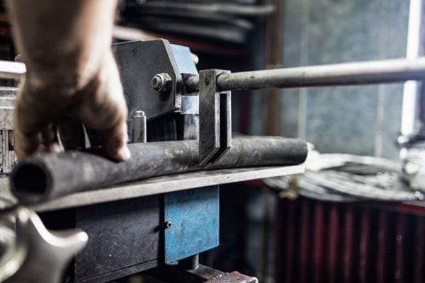
Incorrectly installed fittings can lead to significant issues, including fluid leaks, pressure drops, and even complete system failures. These problems not only reduce the efficiency of the hydraulic system but can also lead to costly repairs and downtime. In extreme cases, improper installation may pose serious safety hazards to operators and equipment. Therefore, understanding the correct procedures for installing hydraulic flange hose fittings is essential for maintaining system integrity and ensuring safe and efficient operations.

Understanding Hydraulic Flange Hose Fittings

Components of a Hydraulic Flange Hose Fitting

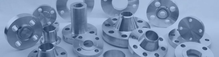
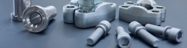
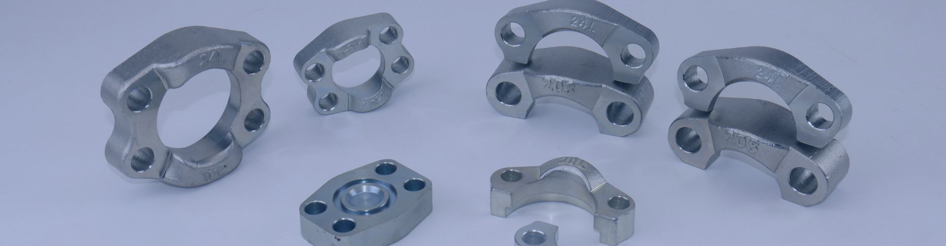
Hydraulic flange hose fittings are composed of several key components, each playing a crucial role in ensuring a secure and leak-proof connection. The primary component is the flange head, which is typically a flat, circular piece of metal with holes around its perimeter. These holes accommodate bolts that secure the flange head to the corresponding flange on the equipment. The hose is connected to the flange head, providing the pathway for hydraulic fluid. To ensure a tight seal, an O-ring is placed between the flange head and the equipment’s flange surface, preventing fluid leaks. Finally, bolts and nuts are used to fasten the assembly together. The bolts pass through the holes in the flange head and are secured with nuts, which are tightened to the appropriate torque to ensure a strong and reliable connection.

Types of Hydraulic Flange Hose Fittings

Hydraulic flange fittings China Manufacturer Topa in China

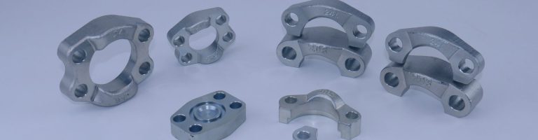
Hydraulic flange hose fittings come in various types, with the most common being Code 61 and Code 62 flanges. Code 61 flanges are designed for medium-pressure applications, typically up to 3,000 PSI, while Code 62 flanges are used in high-pressure systems, handling pressures up to 6,000 PSI. The choice between these two types depends on the specific requirements of the hydraulic system, such as the operating pressure and fluid type.

In addition to pressure ratings, hydraulic flange hose fittings are available in different sizes to accommodate various hose diameters and equipment specifications. The materials used for these fittings can also vary, with options including steel, stainless steel, and aluminum. Steel fittings are known for their strength and durability, making them ideal for heavy-duty applications. Stainless steel fittings offer excellent corrosion resistance, making them suitable for use in harsh environments or with corrosive fluids. Aluminum fittings are lightweight and offer good resistance to corrosion, making them a popular choice for applications where weight is a critical factor.

Applications of Hydraulic Flange Hose Fittings

Hydraulic flange hose fittings are widely used across various industries due to their robust design and reliable performance. Common industries that rely on these fittings include construction, manufacturing, oil and gas, agriculture, and heavy machinery. In these industries, hydraulic systems are often subjected to high pressures and demanding conditions, making the secure and leak-proof connections provided by flange fittings essential.

The benefits of using flange fittings over threaded or welded connections are significant. Flange fittings offer a more stable connection, reducing the risk of leaks and pressure drops. Unlike threaded fittings, which can loosen over time due to vibration or temperature changes, flange fittings remain secure even in challenging conditions. Additionally, flange fittings are easier to install and maintain compared to welded connections, which require specialized equipment and skills. This ease of installation and maintenance makes flange fittings a cost-effective solution for many hydraulic applications, particularly in systems where regular maintenance or component replacement is necessary.

Step-by-Step Installation Guide

Inspecting the Components

Before you begin the installation process, a thorough inspection of all components involved in the hydraulic flange hose fitting is crucial. This step ensures that each part is in optimal condition and ready for assembly. Here’s how to perform this inspection in detail:

Examine the Flange:

Visual Inspection: Start by closely inspecting the flange for any visible damage. Look for cracks, dents, warping, or any other deformities. A perfectly flat flange is essential to create a proper seal, so even minor imperfections can cause significant issues later on.

Surface Condition: Run your fingers along the flange surface to detect any irregularities that may not be visible to the naked eye. The flange surface should be smooth and free from any scratches or nicks that could compromise the seal.

Check the Hose:

Surface Integrity: Unroll the hose and examine it for any cuts, abrasions, or kinks. The hose should be flexible and free from any visible damage. A compromised hose can lead to leaks or failures in the hydraulic system.

Flexibility Test: Gently bend the hose along its length to ensure it retains its flexibility. Stiff or excessively worn hoses may not function properly under pressure.

Inspect the Sealing Surfaces:

O-Ring Groove: Carefully inspect the groove where the O-ring will sit. This area must be clean, smooth, and free from any debris or contamination. Even a small particle can prevent the O-ring from sealing correctly, leading to potential leaks.

Flange Face: Similarly, check the flange face where it will meet the mating surface. Ensure that there is no dirt, rust, or other contaminants present. Clean the surface with a lint-free cloth if necessary.

Preparing the Hose

Once all components have passed the inspection, the next step is to prepare the hose for assembly. Proper preparation of the hose is critical to ensuring a secure and leak-free connection. Follow these detailed steps:

Measure and Mark the Hose:

Accurate Measurement: Measure the hose to the required length based on your system’s specifications. Use a measuring tape and ensure accuracy to avoid any unnecessary adjustments later.

Marking the Cut: Use a permanent marker to clearly mark the point where the hose needs to be cut. This ensures precision during the cutting process.

Cutting the Hose:

Selecting the Right Tool: Use a hose cutter or a sharp blade specifically designed for cutting hydraulic hoses. A clean, straight cut is essential to ensure the hose seats are properly in the fitting.

Making the Cut: Position the hose cutter at the marked point and apply even pressure to make a clean cut. Avoid using saws or dull blades that could fray or damage the hose ends.

Cleaning the Hose Ends:

Inspect the Cut Ends: After cutting, inspect the hose ends to ensure they are clean, smooth, and free from any fraying. A clean cut is vital for creating a tight seal within the flange fitting.

Debris Removal: Use a lint-free cloth to wipe the hose ends. You can also use compressed air to blow out any small particles or debris. Ensure that no contaminants are present that could interfere with the sealing process.

Hydraulic Hose Assembly cut hose

Assembling the Flange Fitting

With the hose prepared, you can now begin the assembly of the flange fitting. Proper alignment and placement of components are crucial in this step. Follow these detailed instructions:

Aligning the Hose with the Flange Head:

Proper Seating: Carefully insert the prepared hose end into the flange head. Ensure that the hose is fully seated within the fitting and that there are no gaps or misalignments.

Visual and Tactile Check: Visually confirm that the hose is aligned straight with the flange head. You can also feel the connection to ensure it is secure and snug.

Positioning the O-Ring:

Selecting the Correct O-Ring: Choose an O-ring that is compatible with the flange fitting and the hydraulic system’s specifications. Ensure that it is free from defects or damage.

Placing the O-Ring: Gently place the O-ring into the groove in the flange head. The O-ring should sit snugly without any twists, kinks, or deformations. Use your fingers to lightly press the O-ring into place, ensuring it is fully seated in the groove.

Lubrication (Optional): If recommended by the manufacturer, apply a light coating of hydraulic fluid or O-ring lubricant to the O-ring. This can help the O-ring slide into place without damage and improve the seal.

Double-Checking the Assembly:

Final Inspection: Before moving on, double-check the alignment of the hose and the placement of the O-ring. Ensure that all components are correctly positioned and that there are no visible issues.

Securing the Flange with Bolts and Nuts

Once the flange fitting is assembled, it is time to secure it to the equipment using bolts and nuts. This step requires precision to ensure a leak-proof connection. Here’s how to do it:

Inserting the Bolts:

Proper Alignment: Align the flange head with the corresponding flange on the equipment. Insert the bolts through the holes in the flange head, ensuring that each bolt is properly aligned with the corresponding hole in the mating flange.

Hand-Tightening the Bolts: Start by hand-tightening the bolts. This helps to bring the flange components together without causing misalignment. Tighten each bolt a little at a time, working in a crisscross pattern to ensure even pressure distribution.

Tightening the Bolts with a Torque Wrench:

Selecting the Correct Torque Setting: Refer to the manufacturer’s specifications for the recommended torque settings. Using the correct torque is crucial to prevent over-tightening or under-tightening, both of which can cause leaks or damage.

Using the Torque Wrench: Begin tightening the bolts with a torque wrench, again working in a crisscross pattern. Apply even pressure and tighten the bolts gradually, checking the torque setting with each turn. Ensure that all bolts are tightened to the specified torque without exceeding the recommended limits.

Final Check:

Uniform Tightening: After all bolts have been tightened, do a final check to ensure that they are uniformly tightened and that the flange is properly seated against the mating surface. There should be no visible gaps or misalignment.

Install Hydraulic Flange Hose Fittings

Final Inspection and Testing

With the flange securely fastened, the installation process is nearly complete. However, a final inspection and pressure testing are essential to confirm the integrity of the installation. Follow these steps:

Final Visual Inspection:

Alignment Check: Inspect the assembly to ensure that the flange, hose, and bolts are properly aligned. There should be no visible gaps or misalignment.

O-Ring Inspection: Confirm that the O-ring is correctly seated and has not shifted during the tightening process.

Pressure Testing:

Gradual Pressurization: Gradually pressurize the hydraulic system to the operating pressure. Monitor the flange fitting closely for any signs of fluid leakage or pressure drops.

Leak Detection: Use a leak detection solution or sensor to identify any small leaks that might not be visible to the naked eye. Pay close attention to the areas around the flange and hose connection.

Addressing Issues:

Leak Response: If any leaks are detected, depressurize the system immediately and recheck the installation. Pay particular attention to the O-ring placement and bolt torque. Adjust as necessary and retest until no leaks are present.

Common Installation Mistakes and How to Avoid Them

Incorrect Torque Application

Incorrect torque application is a prevalent issue that can have serious consequences for the integrity of your hydraulic system. When bolts are over-tightened, the excessive force can cause the flange to deform, which in turn compromises the flatness required for a proper seal. This deformation can also damage the O-ring by either flattening it too much or even causing it to extrude from its groove, both of which can lead to leaks. Over time, the stress caused by over-tightening may weaken the bolts themselves, leading to potential failures under pressure.

Conversely, under-tightening the bolts poses its risks. Without sufficient torque, the flange and hose may not be securely fastened, leading to inadequate sealing. This can allow hydraulic fluid to seep out, which not only reduces system efficiency but also creates a safety hazard due to fluid leaks. Additionally, under-tightened bolts can loosen over time, particularly in systems subject to vibration, further exacerbating the problem.

To ensure the correct torque is applied:

Use a calibrated torque wrench: This is essential for applying the precise amount of torque specified by the manufacturer. Regular calibration checks on the wrench are necessary to maintain accuracy.

Follow the manufacturer’s torque specifications: These guidelines are provided to ensure the bolts are tightened to the exact pressure needed for a secure seal without damaging the components.

Tighten bolts in a crisscross pattern: This method evenly distributes pressure across the flange, preventing warping and ensuring a uniform seal. Gradually increase the torque in small increments until the specified value is reached.

Improper O-ring Placement

The O-ring plays a crucial role in sealing the connection between the flange and the hose. Improper placement of the O-ring is a common mistake that can compromise the entire system. If the O-ring is twisted or pinched during installation, it will not sit flat in its groove, leading to an incomplete seal and potential leaks. Additionally, if the groove contains any dirt or debris, the O-ring may not seat properly, further increasing the risk of leaks.

To avoid improper O-ring placement:

Inspect and clean the O-ring groove: Before installing the O-ring, thoroughly inspect the groove to ensure it is clean and smooth. Use a lint-free cloth to remove any debris or particles.

Position the O-ring correctly: Carefully place the O-ring into the groove, ensuring it sits flat without any twists or pinches. Take your time during this step to avoid misalignment.

Use lubricant if necessary: A light coating of hydraulic fluid or a recommended O-ring lubricant can help the O-ring slide into place more easily and form a better seal. This also reduces the risk of the O-ring getting damaged during installation.

Misalignment of Flange Components

Misalignment during the assembly of flange components is another frequent issue that can lead to uneven pressure distribution and improper sealing. Misalignment often occurs when the bolts are not tightened in the correct sequence or when the hose is not properly aligned with the flange head during assembly. This can cause the flange to warp, resulting in leaks and potential system failure.

To ensure proper alignment:

Align the hose with the flange head: Before inserting the bolts, make sure the hose is properly seated within the flange head. This initial alignment is crucial for preventing misalignment during the tightening process.

Tighten bolts in a crisscross pattern: As with torque application, tightening the bolts in a crisscross pattern helps to evenly distribute pressure across the flange. This method prevents one side from being pulled tighter than the other, reducing the risk of warping or misalignment.

Use alignment tools if available: If available, use alignment tools or jigs to hold the flange components in place during the initial tightening. These tools can help maintain alignment and ensure a more accurate assembly.

Skipping Pre-Installation Inspection

Skipping the pre-installation inspection is a critical mistake that can lead to numerous problems during and after installation. Failing to inspect components thoroughly can result in the use of damaged or contaminated parts, which can compromise the integrity of the entire hydraulic system. For example, a small crack in the flange or a tiny particle in the O-ring groove can lead to leaks, failures, and even catastrophic system issues.

To avoid these pitfalls:

Conduct a detailed inspection of all components: Before starting the installation, thoroughly inspect each component. Look for any signs of damage, such as cracks, warping, or corrosion on the flange. Check the hose for cuts, abrasions, or wear that could compromise its integrity.

Ensure cleanliness: Cleanliness is crucial in hydraulic systems. Make sure the O-ring and sealing surfaces are clean and free from any contaminants. Use appropriate cleaning methods, such as wiping with a lint-free cloth or blowing out debris with compressed air.

Conclusion

Properly installed fittings provide a secure and durable connection, which is essential for maintaining the integrity and safety of the entire system. A well-installed flange hose fitting contributes not only to the smooth operation of machinery but also to the overall safety of the workplace, protecting both equipment and personnel from potential hazards.

FAQ

Hydraulic flange hose fittings are components used to securely connect hoses to hydraulic equipment, ensuring a leak-proof seal and stable fluid flow.

Choose a fitting based on the pressure rating (e.g., Code 61 or Code 62), size, material (e.g., steel, stainless steel), and compatibility with your hydraulic system.

Proper torque ensures that the bolts are neither too tight nor too loose, preventing damage to the flange and ensuring a secure, leak-free connection.

Inspect the flange, hose, and O-ring for any damage or contamination, and ensure all components are clean and in good condition before installation.

Leaks can be caused by improper O-ring placement, misalignment of components, or incorrect torque application during installation.

Regular inspections should be conducted according to your system’s maintenance schedule, with immediate attention given to any signs of wear, damage, or leaks.

How to Choose the Right Hydraulic Adapters

How to Choose the Right Hydraulic Adapters

How to Choose the Right Hydraulic Adapters

Table of Contents

Introduction

Hydraulic adapter fittings play a crucial role in connecting different components within a hydraulic system, ensuring seamless fluid transfer and system integrity. The purpose of this post is to guide readers through the essential factors to consider when selecting hydraulic adapter fittings, providing practical tips and expert advice to help make informed decisions.

Key Factors to Consider 

Material Compatibility

Corrosion Resistance: The material of the hydraulic adapter must be resistant to corrosion, especially if it will be used in environments where exposure to moisture, chemicals, or saltwater is common. Stainless steel is often preferred in such conditions due to its excellent corrosion resistance. However, for less corrosive environments, brass or plated steel might be adequate. Corrosion not only shortens the lifespan of the adapter but also can lead to contamination of the hydraulic fluid, which could damage the entire system.

Strength and Durability: Different materials offer varying levels of strength and durability. For high-pressure applications, steel or stainless steel adapters are typically required because of their superior strength. Brass, while easier to machine and less prone to galling, is better suited for lower-pressure applications. Durability also extends to the adapter’s resistance to wear and tear, which is crucial in applications involving frequent assembly and disassembly.

Pressure Rating

Maximum Operating Pressure: Each hydraulic adapter is designed to withstand a specific range of pressures. It’s essential to match the adapter’s pressure rating with the maximum operating pressure of your hydraulic system. Using an adapter with a lower pressure rating can result in catastrophic failure, leading to system leaks, equipment damage, and even safety hazards.

Safety Margins: When selecting an adapter, consider incorporating a safety margin above the system’s maximum operating pressure. This margin accounts for unexpected spikes in pressure and ensures that the adapter will perform reliably even under slightly higher pressures than anticipated.

Thread Type and Size

Thread Compatibility: The thread type is crucial because it determines how the adapter connects with other components. Common thread types include NPT (National Pipe Taper), BSP (British Standard Pipe), and JIC (Joint Industry Council). Mismatched threads can lead to improper sealing, resulting in leaks and potential damage. It’s essential to identify the thread standards used in your system and select an adapter that matches these standards.

Thread Size: Accurate thread size ensures a proper fit, which is critical for creating a secure, leak-proof connection. Threads that are too large or too small can cause misalignment, leading to cross-threading or inadequate sealing, which compromises the integrity of the hydraulic system.

FS2405 ORFS Adapter drawing Topa

Seal Type

O-Ring Seals: O-Ring seals are a popular choice for many hydraulic applications due to their ability to create a tight seal, even under high pressure. They are typically made from elastomers such as Nitrile (Buna-N), Viton, or EPDM, which offer different levels of resistance to heat, chemicals, and wear. O-rings are often used in applications where preventing leaks is critical.

Metal-to-Metal Seals: Metal-to-metal seals are used in situations where high pressure or temperature may cause elastomeric seals to fail. These seals rely on the precise machining of metal surfaces to create a tight fit, which can handle extreme conditions. However, they require careful installation to avoid damage to the sealing surfaces, which could lead to leaks.

Temperature Range

Operating Temperature: Hydraulic systems often operate in environments with varying temperatures, so it’s important that the adapter and its seals can withstand the temperature extremes without compromising performance. High temperatures can cause elastomeric seals to harden and lose elasticity, leading to leaks, while low temperatures can cause seals to become brittle and crack.

Thermal Expansion: Different materials expand and contract at different rates when exposed to temperature changes. If the thermal expansion of the adapter material is not compatible with the system, it can lead to loosening or overtightening of connections. This can cause leaks or damage to the adapter and other components.

Fluid Compatibility

Chemical Resistance: The hydraulic fluid used in your system must be compatible with the material of the adapter and its seals. Some fluids can cause certain materials to degrade, leading to leaks and contamination. For example, synthetic fluids may require seals made from Viton rather than Nitrile due to Viton’s superior chemical resistance.

Contamination Prevention: Hydraulic adapter fittings should be designed to minimize the risk of fluid contamination. Contaminants in hydraulic fluid can cause significant wear and tear on the system’s components, leading to reduced efficiency and possible system failure. Smooth internal surfaces and proper sealing are critical to preventing the ingress of contaminants.

System Configuration

Flow Capacity: The design and size of the adapter must accommodate the required flow rate of the hydraulic system. An undersized adapter can create a bottleneck, causing excessive pressure drops, reduced system efficiency, and potential overheating. On the other hand, an oversized adapter might not fit properly or may be more expensive than necessary.

Space and Installation Constraints: The physical size and shape of the adapter should be compatible with the space available in the system. In tight spaces, compact adapters or those with angled connections (such as elbow adapters) may be necessary. Additionally, the adapter must be easy to access for installation, maintenance, and inspection purposes.

Application Requirements

Specific Industry Standards: Many industries have specific standards and regulations that dictate the type of hydraulic adapter fittings that must be used. For example, the aerospace industry often requires components to meet stringent specifications for reliability and safety. Understanding and adhering to these standards is crucial for compliance and performance.

Environmental Considerations: Depending on the operating environment, you may need to choose adapters that are resistant to extreme conditions such as high humidity, saltwater, dust, or chemical exposure. This ensures that the adapter remains functional and reliable throughout its service life.

Common Mistakes to Avoid 

Ignoring Pressure Ratings

Mistake: One of the most critical mistakes when selecting hydraulic adapter fittings is overlooking or underestimating the importance of pressure ratings. Many assume that all adapters can withstand similar pressures or that the pressure rating is not a significant factor in the selection process.

Consequence: Using an adapter with a pressure rating lower than the system’s maximum operating pressure can have serious consequences. Under high-pressure conditions, the adapter may not be able to handle the load, leading to catastrophic failure. This can cause hydraulic fluid leaks, which are not only messy and costly to clean up but can also pose significant safety hazards, such as fires or environmental contamination. Moreover, equipment damage resulting from pressure-induced failure can lead to extensive downtime, expensive repairs, and even the need to replace entire components or systems.

Solution: To avoid these risks, it is essential to always verify the pressure rating of any hydraulic adapter you intend to use. Ensure that the adapter’s rating meets or, preferably, exceeds the maximum pressure requirements of your hydraulic system. This practice includes factoring in any potential pressure spikes that may occur during operation, providing a safety margin to further protect against unexpected failures. Taking the time to select adapters with the appropriate pressure rating will enhance the reliability and safety of your hydraulic system.

Overlooking Material Compatibility

Mistake: Another common oversight is choosing hydraulic adapter fittings made from materials that are not compatible with the hydraulic fluid or the environmental conditions in which the system operates. This mistake often occurs when cost is prioritized over material selection, or when the specific requirements of the system are not fully understood.

Consequence: When materials are incompatible with the hydraulic fluid, they can corrode, weaken, or degrade over time. This degradation can lead to leaks, contamination of the hydraulic fluid, and ultimately, the failure of the entire system. Corrosion can be particularly insidious, as it may go unnoticed until a significant problem arises, at which point the damage can be extensive. Additionally, the contamination of hydraulic fluid can cause damage to other components within the system, leading to further maintenance issues and costly repairs.

Solution: To avoid these issues, it is crucial to carefully match the material of the hydraulic adapter with both the hydraulic fluid and the environmental conditions it will be exposed to. For instance, in systems using aggressive fluids or operating in harsh environments, materials like stainless steel or specialized alloys may be necessary due to their corrosion resistance and chemical compatibility.  

Mismatching Thread Types

Mistake: Mismatching thread types or sizes is a frequent mistake that can have serious repercussions for hydraulic systems. This mistake often occurs due to a lack of awareness about the different thread standards or a failure to ensure that all components within the system are compatible.

Consequence: Using mismatched threads, such as mixing NPT (National Pipe Taper) with BSP (British Standard Pipe) or JIC (Joint Industry Council) threads, can result in improper sealing, leading to leaks. Cross-threading is another risk, where threads become damaged during assembly, making it difficult to achieve a proper seal or to disassemble the components later. This can lead to costly repairs or replacements, as well as system downtime while the issues are resolved. Furthermore, leaks in hydraulic systems can lead to a loss of efficiency, increased operational costs, and potential safety hazards.

Solution: The solution is to ensure that all thread types and sizes within the hydraulic system are compatible and properly matched. This includes not only selecting adapters with the correct thread type but also verifying the thread pitch and diameter to ensure a perfect fit. It may be helpful to use thread identification tools or consult with experts to confirm the compatibility of different components. Additionally, using adapters that conform to industry standards can reduce the risk of mismatched threads, leading to a more reliable and efficient hydraulic system.

Hydraulic Bulkhead Fittings Fail

Neglecting Seal Compatibility

Mistake: Seals are a critical component in hydraulic systems, and neglecting their compatibility with the hydraulic fluid or the system’s operating temperature is a common mistake. This often happens when seals are selected based solely on their initial cost or availability, without considering their performance characteristics.

Consequence: Incompatible seals can harden, crack, or degrade over time, particularly if exposed to temperatures or fluids for which they were not designed. This degradation can lead to leaks, which not only reduce system efficiency but also pose safety risks. In severe cases, the loss of hydraulic fluid pressure due to failed seals can cause the system to become inoperable, leading to costly downtime and repairs.

Solution: To avoid these issues, it is essential to select seals that are specifically designed for the hydraulic fluid and operating temperature range of your system. This includes considering factors such as chemical resistance, temperature tolerance, and flexibility. For example, Viton seals may be chosen for their superior chemical resistance and temperature tolerance, while Nitrile (Buna-N) seals might be preferred for general-purpose applications. By selecting the appropriate seals for your system, you can ensure long-term performance and reliability, reducing the likelihood of leaks and system failures.

Failing to Consider Thermal Expansion

Mistake: Failing to account for the thermal expansion properties of the adapter material is a mistake that can have significant consequences, particularly in systems that operate across a wide range of temperatures. This oversight often occurs when material selection is based solely on pressure rating or cost, without considering the impact of temperature fluctuations.

Consequence: When hydraulic systems experience temperature changes, the materials used in the adapters and other components will expand or contract. If the thermal expansion properties of the adapter material are not compatible with the rest of the system, it can cause the adapter to either loosen or over-tighten. This can lead to leaks, as the seal between the adapter and the other components is compromised. In extreme cases, thermal expansion can cause damage to the threads or other parts of the system, leading to costly repairs or replacements.

Solution: The solution is to choose materials that have suitable thermal expansion properties for the operating temperature range of your hydraulic system. This may involve selecting materials that expand and contract at similar rates as the rest of the system components, or using temperature-compensating designs that allow for movement without compromising the seal. Additionally, consider the use of flexible connections or expansion joints in systems that experience significant temperature variations.

Overlooking Flow Capacity

Mistake: Overlooking the flow capacity of the hydraulic adapter is a mistake that can lead to inefficiencies and performance issues in the hydraulic system. This often occurs when the focus is solely on the pressure rating or material compatibility, without considering how the adapter’s size and design will impact fluid flow.

Consequence: An undersized adapter can create a bottleneck in the system, restricting fluid flow and causing pressure drops. This can lead to a reduction in system efficiency, as the hydraulic pump has to work harder to maintain the desired pressure and flow rate. Over time, this increased workload can lead to overheating, wear and tear on the pump, and ultimately, system failure. In addition, restricted flow can result in slower response times and reduced overall performance of the hydraulic system.

Solution: To avoid these issues, it is essential to select adapters that are appropriately sized for the flow capacity required by your hydraulic system. This includes considering both the internal diameter of the adapter and its design, as certain shapes or configurations may introduce additional restrictions. It may be necessary to consult flow rate charts or use hydraulic simulation software to ensure that the chosen adapters will allow for the required flow rate without causing pressure drops or turbulence.

Disregarding Industry Standards

Mistake: Disregarding industry standards when selecting hydraulic adapter fittings is a mistake that can lead to compatibility issues, safety risks, and regulatory compliance problems. This often happens when cost or convenience is prioritized over adherence to established standards.

Consequence: Using adapters that do not comply with industry standards can result in system incompatibility, as the components may not fit together properly or may not perform as expected. This can lead to leaks, equipment damage, and safety hazards. In addition, non-compliant adapters may not meet the regulatory requirements for certain industries, leading to potential fines, legal issues, and the need to replace non-compliant components. Furthermore, disregarding standards can make it difficult to source replacement parts or to ensure consistent performance across different systems.

Solution: The solution is to always select adapters that meet the relevant industry standards for your application. This includes standards set by organizations such as ISO (International Organization for Standardization), SAE (Society of Automotive Engineers), and others. These standards ensure that the adapters are designed and manufactured to meet specific performance and safety criteria, providing a higher level of reliability and consistency.

Conclusion

As you make your selection, it is vital to prioritize quality and compatibility over cost alone. Investing in high-quality, well-matched adapters will not only enhance system efficiency but also reduce the likelihood of costly downtime and repairs. I encourage you to take a closer look at your current hydraulic systems, assess your adapter needs, and make informed decisions that will support your operations in the long run.

FAQ

The most important factor is ensuring compatibility with your hydraulic system, including matching thread types, sizes, and sealing methods.

Use thread identification tools or consult thread specification charts to accurately determine the correct thread type.

It depends on the specific requirements of each application, such as pressure, temperature, and environmental conditions. Always ensure the adapter is suitable for the intended use.

Stainless steel and brass are commonly recommended materials for hydraulic adapter fittings in corrosive environments due to their resistance to corrosion.

Hydraulic adaptors should be inspected regularly as part of routine maintenance, ideally every few months, or more frequently in high-stress environments.

Signs include visible wear, corrosion, leaks, or difficulty in maintaining a proper seal. If any of these are observed, the adapter should be replaced immediately.

Stuck Ferrule Fittings Here’s What You Need to Know

Stuck Ferrule Fittings? Here’s What You Need to Know

Stuck Ferrule Fittings? Here’s What You Need to Know

Introduction

Whether due to corrosion, over-tightening, or simply age, a stuck ferrule fitting can be a common yet frustrating issue. But the good news is that this problem is far from insurmountable. The purpose of this post is to arm you with the knowledge and practical solutions needed to deal with stuck ferrule pipe fittings effectively. By understanding the causes behind this issue and learning the right techniques for prevention and removal, you can tackle this challenge with confidence.

Why Ferrule Pipe Fittings Get Stuck

Corrosion and Material Build-Up

One of the most frequent culprits behind stuck ferrule pipe fittings is corrosion. Over time, exposure to moisture, chemicals, and other environmental factors can cause the metal in the fittings to corrode. This corrosion leads to a gradual build-up of material both inside and around the fitting, making it increasingly difficult to remove. Rust and scale can seize the threads, effectively welding the fitting in place. In systems where fluids are transported, especially those that carry corrosive substances, the risk of corrosion is even higher. Regular exposure to such conditions accelerates the process, often making it nearly impossible to unscrew the fitting without causing damage.

Over-Tightening During Installation

Another common reason for stuck ferrule pipe fittings is over-tightening during installation. In an attempt to ensure a secure connection, it’s easy to apply too much force when tightening the fitting. While it might seem like a good idea at the time, over-tightening can deform the ferrule or the pipe itself, creating an excessively tight seal that becomes difficult to break later. The fitting may become so firmly compressed against the pipe that traditional methods of loosening are ineffective. Over-tightening also increases the risk of damaging the threads, further complicating the removal process.

install ferrule fitting

Misalignment or Improper Installation

Misalignment during installation is another factor that can lead to stuck ferrule fittings. When fittings are not properly aligned with the pipe, it can cause uneven pressure distribution across the ferrule. This misalignment may lead to the ferrule becoming wedged against the pipe, creating friction that makes the fitting extremely difficult to remove. Improper installation, such as not ensuring the fitting is seated correctly or using the wrong type of ferrule, can exacerbate this issue. In some cases, the fitting may have been cross-threaded during installation, which not only makes it hard to remove but also increases the likelihood of damaging the pipe and fitting.

Temperature and Pressure Extremes

Ferrule pipe fittings are often used in environments where they are exposed to extreme temperatures and pressures. Over time, these conditions can cause the fittings to expand and contract, leading to a tighter fit. In high-temperature environments, metal fittings can expand, causing the ferrule to become even more tightly bound to the pipe. Conversely, in low-temperature settings, the metal may contract, but the differential in expansion rates between the fitting and the pipe can still result in a stuck fitting. High pressure within the system can also exacerbate this issue, forcing the ferrule more firmly against the pipe and making it harder to dislodge.

Signs of Stuck Ferrule Fittings

Identifying a stuck ferrule fitting early can prevent more serious problems down the line. Here are some common signs that indicate a ferrule fitting may be stuck or becoming difficult to remove:

Increased Resistance During Disassembly

When attempting to unscrew the fitting, you may notice an unusual level of resistance, even when applying the correct amount of torque. This resistance could indicate that the fitting is seized due to corrosion, over-tightening, or other factors.

Visible Corrosion or Rust

If you see rust or corrosion around the fitting, it’s a strong indicator that the fitting may be stuck. Corrosion can cause the metal to bind together, making it extremely difficult to loosen the fitting without damaging it.

Deformation of the Fitting or Pipe

Check for any visible signs of deformation, such as bent or misshaped ferrules, nuts, or pipes. Deformation can occur due to over-tightening or misalignment, both of which can cause the fitting to get stuck.

install ferrule fitting Topa

Difficulty Achieving a Tight Seal

If you’re having trouble achieving a tight seal when installing the fitting, it could be a sign that the ferrule is not properly aligned or is becoming stuck. A poor seal might also indicate that the fitting is already damaged or corroded, leading to difficulties during removal.

Leakage Around the Fitting

Any signs of leakage around the fitting, whether it’s a small drip or a more significant flow, can indicate that the fitting is compromised and may be stuck. This is particularly important in pressurized systems where even a minor leak can lead to larger problems.

Unusual Noises During Tightening or Loosening

Listen for any unusual noises, such as squeaking, grinding, or popping sounds, when tightening or loosening the fitting. These noises can indicate that the metal components are binding together, making the fitting more likely to become stuck.

Discoloration or Stains Around the Fitting

Discoloration or stains around the fitting area might suggest that fluids have been leaking or that the fitting has been exposed to corrosive substances. This can lead to a stuck fitting if not addressed promptly.

Excessive Force Required for Installation or Removal

If you find that you’re needing to use excessive force during the installation or removal of the fitting, it’s a clear sign that something is wrong. This could be due to misalignment, corrosion, or over-tightening, all of which can cause the fitting to become stuck.

Cracking or Splitting of the Ferrule or Nut

Inspect the ferrule and nut for any signs of cracking or splitting, which can occur if the fitting is forced beyond its design limits. A cracked ferrule or nut may indicate that the fitting is stuck and requires careful attention to avoid further damage.

Difficulty in Aligning the Fitting During Installation

If you’re struggling to properly align the fitting with the pipe during installation, it could be a sign that the ferrule is binding or that there’s a build-up of material preventing proper seating. This misalignment can lead to a stuck fitting over time.

How to Free Stuck Ferrule Pipe Fittings

Safety Precautions

Before attempting to free a stuck ferrule pipe fitting, it’s crucial to prioritize safety. Improper handling of stuck fittings can lead to injuries, damage to the piping system, or even catastrophic failures in high-pressure environments. Here are some essential safety guidelines:

Turn Off the System: Ensure that the system is completely depressurized and any fluid flow is stopped before attempting to remove a fitting. This prevents accidental leaks or bursts that could cause injury.

Vent the Line: If the system contains hazardous or pressurized fluids, make sure to vent the line to release any trapped pressure. This is especially important in systems carrying gases or high-pressure fluids.

Use Appropriate Personal Protective Equipment (PPE): Always wear safety goggles to protect your eyes from debris or fluid spray. Heavy-duty gloves should be used to protect your hands from sharp edges or hot surfaces. In some cases, a face shield and protective clothing may also be necessary.

Work in a Well-Ventilated Area: If you’re using chemical lubricants or applying heat, make sure you’re working in a well-ventilated area to avoid inhaling fumes.

Be Aware of Surroundings: Ensure that there is adequate space around your work area to maneuver tools safely and that no other workers are nearby who could be affected by your actions.

Step-by-Step Removal Process

When dealing with a stuck ferrule pipe fitting, there are several methods you can try to free it. Below are detailed step-by-step instructions for each method:

Method 1: Gentle Tapping and Lubricant Application

Apply Penetrating Oil:

Begin by applying a generous amount of penetrating oil around the ferrule and fitting threads. Allow the oil to seep in for at least 10-15 minutes, or longer if the fitting has been stuck for an extended period. The oil will help to break down rust, corrosion, and other build-ups that may be causing the fitting to seize.

Tap Gently with a Hammer:

Using a small hammer, gently tap around the fitting to help the penetrating oil penetrate deeper and loosen the bond between the ferrule and the pipe. Avoid excessive force, as this could damage the fitting or pipe.

Attempt to Unscrew the Fitting:

After allowing the oil to work, use a wrench to carefully attempt to unscrew the fitting. Apply steady, even pressure to avoid stripping the threads or deforming the fitting. If the fitting begins to move, continue applying lubricant as you work it loose.

Repeat as Necessary:

If the fitting remains stuck, repeat the process of applying oil and tapping. Sometimes, several rounds of this procedure are required to free a particularly stubborn fitting.

Method 2: Use of Heat to Expand the Fitting

Prepare the Area:

Ensure the area around the fitting is clear of flammable materials. If necessary, use a heat shield to protect nearby components from the heat.

Apply Controlled Heat:

Using a heat gun or torch, apply controlled heat directly to the ferrule fitting. The goal is to expand the metal fitting slightly, breaking the bond caused by corrosion or material build-up. Be careful not to overheat the fitting, as excessive heat can weaken the metal or damage the pipe.

Attempt to Loosen the Fitting:

Once the fitting is heated, use a wrench to attempt to unscrew it. The expansion of the metal should make it easier to turn. If the fitting starts to move, continue applying heat while gently turning it to prevent it from sticking again as it cools.

Cool and Reapply Lubricant:

If successful, cool the fitting with water or a damp cloth to return it to normal size. Apply more lubricant during the cooling process to prevent it from seizing again.

Method 3: Specialized Tools for Extracting Ferrules

Select the Right Tool:

There are specialized tools available for removing ferrules from pipes without damaging the surrounding components. Choose a tool designed specifically for the type and size of ferrule you are dealing with.

Position the Tool:

Position the ferrule removal tool around the fitting, ensuring it is securely clamped onto the ferrule. Follow the manufacturer’s instructions for proper use.

Apply Pressure:

Gradually apply pressure using the tool to extract the ferrule. The tool will either pull the ferrule off the pipe or compress it, breaking the seal and allowing for easy removal.

Inspect for Damage:

Once the ferrule is removed, inspect the pipe and fitting for any damage. If the pipe is undamaged, you can proceed with installing a new ferrule.

Method 4: Cutting and Replacing the Fitting When Necessary

Mark the Cut Location:

If all other methods fail, the last resort is to cut off the fitting. Mark the location on the pipe where you will make the cut, ensuring that you leave enough pipe length to install a new fitting.

Cut the Fitting:

Use a pipe cutter or hacksaw to carefully cut through the ferrule and fitting. Take your time to ensure a clean, straight cut to prevent future sealing issues.

Remove the Cut Section:

Once the fitting is cut, remove the damaged section from the pipe. You may need to clean the pipe end to remove any debris or burrs left from cutting.

Install a New Fitting:

After cutting, inspect the remaining pipe for any signs of damage. If the pipe is in good condition, proceed with installing a new ferrule fitting according to the manufacturer’s specifications.

Test the System:

After the new fitting is installed, test the system for leaks and ensure that the fitting is secure. Check for any signs of weakness or improper sealing.

Conclusion

To recap, it’s essential to recognize the signs of a stuck ferrule fitting early on, such as increased resistance during disassembly or visible corrosion, to prevent further complications. Employing the correct removal techniques and using high-quality materials can significantly reduce the risk of future issues. If you find yourself struggling with a particularly stubborn fitting or need professional assistance, don’t hesitate to contact our team.

FAQ

Start by applying penetrating oil and using gentle tapping to loosen the fitting. If that doesn’t work, try applying controlled heat or using specialized tools.

Yes, with the right tools and techniques, you can usually remove a stuck fitting without damaging the pipe. If necessary, you can also cut and replace the fitting.

If all attempts to remove the fitting fail, or if the fitting or pipe is damaged during removal, it’s best to replace the fitting to ensure system integrity.

You’ll need tools like wrenches, penetrating oil, a heat gun or torch, ferrule removal tools, and possibly cutting tools, depending on the severity of the situation.

Common causes include corrosion, over-tightening during installation, misalignment, and exposure to extreme temperatures or pressures.

Regular maintenance, proper installation techniques, using the right materials, and avoiding over-tightening can help prevent fittings from becoming stuck.

Hydraulic Adapter vs Coupler Understanding Key Differences

Hydraulic Adapter vs Coupler: Understanding Key Differences

Hydraulic Adapter vs Coupler: Understanding Key Differences

Introduction

Hydraulic systems are the backbone of numerous industries, from manufacturing to construction, enabling efficient power transmission and precise control in various applications. These systems rely heavily on robust connections, such as hydraulic adapters and couplers, to ensure seamless operation. However, choosing the right component for your system is crucial, as each serves distinct purposes and offers different benefits. In this post, we will explore the key differences between hydraulic adapters and couplers, helping you understand their unique applications and guiding you in making informed decisions for your hydraulic system’s needs.

Overview of Hydraulic Systems

Definition

A hydraulic system is a technology that utilizes fluid power to perform work by transmitting force through a fluid, usually a type of oil or hydraulic fluid. The basic principle behind hydraulic systems is Pascal’s Law, which states that when a fluid is confined and under pressure, the pressure is exerted equally in all directions. This allows hydraulic systems to generate large amounts of force from relatively small inputs, making them highly efficient and powerful. Hydraulic systems consist of several key components, including a pump (which moves the fluid), valves (which control the flow and pressure of the fluid), actuators (such as cylinders or motors that convert fluid power into mechanical work), and hydraulic fluid (which transmits the power).

These systems are widely used in various industries, such as construction, manufacturing, agriculture, and aviation, due to their ability to provide consistent power, precise control, and the capacity to handle heavy loads. Whether it’s lifting heavy equipment, operating machinery, or controlling complex movements, hydraulic systems are indispensable in modern industrial applications.

Importance

Connectors, including adapters and couplers, play a crucial role in maintaining the efficiency, safety, and reliability of hydraulic systems. The effectiveness of a hydraulic system largely depends on its ability to maintain a sealed environment where fluid can flow without leaks or interruptions. This is where connectors come into play. They serve as the linking points between different components of the system, ensuring that fluid flows smoothly from one part to another without loss of pressure or fluid.

Hydraulic adapters and couplers are essential in managing the connections within these systems, accommodating different thread types, sizes, and configurations. Adapters help in bridging components with mismatched threads or sizes, allowing them to connect securely without compromising the system’s integrity. On the other hand, couplers, particularly quick-disconnect types, enable fast and efficient connection and disconnection of hoses and other components, which is especially useful in systems requiring frequent maintenance or component changes.

What is a Hydraulic Coupler?

A hydraulic coupler is a specialized component within hydraulic systems designed to enable quick, secure, and often leak-free connections and disconnections between various hydraulic components, such as hoses, pipes, and machinery. Hydraulic couplers are vital in applications where components need to be frequently connected or disconnected without compromising the system’s integrity or efficiency. These couplers are engineered to maintain the system’s pressure and prevent fluid loss during connection and disconnection, which is crucial for maintaining the performance and safety of hydraulic systems.

Coupler Applications

Types of Hydraulic Couplers

Quick-Disconnect Couplers

Quick-disconnect couplers are one of the most widely used types of hydraulic couplers, known for their ability to facilitate fast and easy connections and disconnections without requiring tools. These couplers are designed to engage and disengage with a simple push or pull mechanism, allowing operators to quickly connect or disconnect hydraulic lines as needed. The primary advantage of quick-disconnect couplers is their ability to provide a leak-free seal when connected, ensuring that hydraulic fluid does not escape during operation.

Threaded Couplers

Threaded couplers are used in hydraulic systems where a more permanent and secure connection is required. Unlike quick-disconnect couplers, threaded couplers require manual threading to connect or disconnect components, providing a tighter and more secure seal. This type of coupler is often used in applications where the hydraulic connection needs to withstand higher pressures or where the connection is not intended to be frequently disconnected. Threaded couplers are commonly found in systems that operate in harsh environments or under heavy loads, such as in industrial machinery, oil and gas operations, and heavy-duty vehicles.

Flat-Face Couplers

Flat-face couplers are designed with a specific focus on minimizing fluid spillage during connection and disconnection. This type of coupler features a flat mating surface, which prevents fluid from escaping when the coupler is disconnected, making it ideal for use in clean or sensitive environments where fluid leakage could cause contamination or safety hazards. Flat-face couplers are commonly used in industries such as food processing, pharmaceuticals, and clean room environments, where maintaining a clean and controlled environment is critical. Additionally, flat-face couplers are often used in mobile equipment that operates in sensitive ecological areas, as they help prevent hydraulic fluid from leaking into the environment.

Materials Used

Hydraulic couplers are manufactured from a range of materials, each selected based on the specific requirements of the application, including durability, corrosion resistance, and cost.

Steel: Steel is a commonly used material for hydraulic couplers due to its strength and durability. Steel couplers can withstand high pressures and are suitable for demanding applications where the hydraulic system is exposed to heavy loads and harsh conditions. However, steel is susceptible to corrosion, so it is often treated with coatings or plating to enhance its resistance to rust and wear.

Stainless Steel: Stainless steel couplers are preferred in environments where corrosion resistance is crucial, such as in marine applications or industries involving exposure to chemicals or corrosive fluids. Stainless steel is more resistant to rust and corrosion than regular steel, making it ideal for long-term use in harsh or corrosive environments. Although stainless steel couplers are more expensive, their durability and resistance to corrosion justify the higher cost in applications where reliability is essential.

Brass: Brass is another material commonly used for hydraulic couplers, especially in applications where moderate pressure levels and corrosion resistance are required. Brass couplers are often found in hydraulic systems that involve water, coolants, or mild chemicals. Brass is easier to machine than steel, which can reduce manufacturing costs, and its natural resistance to corrosion makes it a suitable choice for many applications where cost-effectiveness and durability are important considerations.

What is a Hydraulic Adapter?

A hydraulic adapter is a crucial component in hydraulic systems, designed to connect various components that may have different thread types, sizes, or connection methods. These adapters play an essential role in ensuring that hydraulic systems operate smoothly and efficiently, even when components are not naturally compatible. By accommodating mismatched threads or different connection types, hydraulic adapters provide the necessary link that allows fluids to flow seamlessly through a system, maintaining the integrity and functionality of the overall hydraulic setup.

Hydraulic adapters are often used when there is a need to transition between different thread standards, such as from British Standard Pipe (BSP) to National Pipe Taper (NPT), or to connect components that are positioned at varying angles or locations. Without these adapters, engineers and technicians would face significant challenges in assembling and maintaining hydraulic systems, as incompatible components could lead to leaks, pressure drops, and system failures.

Types of Hydraulic Adapters

Straight Adapters

Straight adapters are one of the most common types of hydraulic adapters used in systems. They serve the straightforward purpose of connecting two components with different thread types or sizes in a linear fashion. For instance, if a hydraulic hose has a BSP thread but needs to be connected to a pump with an NPT thread, a straight adapter would be used to create a secure and leak-free connection between these two components. The simplicity of straight adapters makes them versatile and widely used across various industries, from manufacturing to automotive applications.

Elbow Adapters

Elbow adapters are designed to connect hydraulic components at an angle, typically 45 or 90 degrees. These adapters are particularly useful in systems where space constraints or the layout of components necessitate a change in the direction of fluid flow. For example, in a compact hydraulic system where hoses or pipes need to navigate around obstacles, elbow adapters allow for the redirection of fluid without causing undue stress on the hoses or fittings. By facilitating smooth directional changes, elbow adapters help maintain consistent pressure and flow rates within the system.

Tee Adapters

Tee adapters are specialized hydraulic adapters used to split the flow of fluid into two separate paths or to combine multiple flow paths into one. Shaped like the letter “T,” these adapters are essential in systems where fluid needs to be distributed to multiple components or where two fluid streams need to be merged into a single flow. Tee adapters are commonly used in hydraulic circuits where multiple actuators or cylinders need to be powered simultaneously, ensuring that each receives an adequate supply of hydraulic fluid. The ability to control and direct fluid flow in multiple directions makes tee adapters a valuable component in complex hydraulic systems.

hydraulic adapters manufacturer Topa in China

Materials Used

Hydraulic adapters are manufactured from a variety of materials, each chosen based on specific requirements such as durability, corrosion resistance, and cost-effectiveness.

Steel: Steel is one of the most commonly used materials for hydraulic adapters due to its strength and durability. Steel adapters can withstand high pressures and are often used in heavy-duty applications, such as industrial machinery and construction equipment. However, steel is prone to corrosion, so it is typically coated or treated to enhance its rust resistance.

Stainless Steel: Stainless steel is favored in environments where corrosion resistance is paramount, such as in marine or chemical processing industries. While stainless steel adapters are more expensive than regular steel, their ability to resist rust and corrosion makes them ideal for applications where longevity and reliability are critical.

Brass: Brass is another material commonly used for hydraulic adapters, particularly in systems where moderate pressure levels are present, and corrosion resistance is important. Brass adapters are often found in applications involving water, coolants, or mild chemicals. They are also easier to machine, which can result in lower manufacturing costs compared to steel or stainless steel.

Key Differences Between Hydraulic Adapters and Couplers

Design and Structure

Hydraulic adapters and couplers are both essential components in hydraulic systems, but they differ significantly in their design and physical structure, which directly impacts their function and usage.

Hydraulic Adapters:

Hydraulic adapters are typically simple, cylindrical components designed to connect two different hydraulic components that have incompatible thread types or sizes. They are often made with threaded ends, which allow them to be screwed into the components they are connecting.

Hydraulic Couplers:

On the other hand, hydraulic couplers are designed to facilitate quick and easy connections and disconnections between hydraulic components. Their structure is more complex than that of adapters, as they typically include mechanisms such as spring-loaded sleeves or valves that enable rapid engagement and disengagement.

Functionality

The functionality of hydraulic adapters and couplers is closely tied to their design, with each component playing a distinct role in a hydraulic system.

Hydraulic Adapters:

The primary function of hydraulic adapters is to connect two hydraulic components that have different thread types, sizes, or configurations. Adapters are essential in systems where standardization of threads is not possible, allowing for the integration of components from different manufacturers or with different specifications. For example, an adapter might be used to connect a hose with a British Standard Pipe (BSP) thread to a pump with a National Pipe Taper (NPT) thread. By bridging these incompatible connections, adapters ensure that the hydraulic system can function seamlessly without leaks or pressure drops.

Hydraulic Couplers:

Hydraulic couplers, in contrast, are designed for applications where quick and secure connections and disconnections are necessary. Their main function is to allow operators to easily connect and disconnect hydraulic lines without tools, which is particularly important in environments where components need to be frequently changed, maintained, or moved. For example, in construction equipment, quick-disconnect couplers enable operators to switch between different attachments, such as hydraulic hammers or augers, quickly and without losing hydraulic fluid.

Conclusion

When selecting between an adapter and a coupler, it’s crucial to consider the specific needs of your hydraulic system, such as the need for a secure, permanent connection versus the need for quick changes. By carefully assessing these factors, you can choose the right component to enhance the performance and reliability of your system.

FAQ

Hydraulic adapters connect two hydraulic components with different thread types or sizes, ensuring a secure and leak-free connection.

Use a hydraulic coupler when you need to frequently connect and disconnect components quickly, such as in mobile equipment or systems requiring regular maintenance.

Yes, hydraulic adapters and couplers can be used together to address both thread compatibility and quick connection requirements in a hydraulic system.

Hydraulic couplers are commonly made from materials like steel, stainless steel, and brass, chosen for their durability, corrosion resistance, and suitability for specific applications.

Choose the right hydraulic adapter by matching the thread types, sizes, and material compatibility with your system’s requirements, ensuring a secure and efficient connection.

Yes, hydraulic couplers, especially quick-disconnect types, require regular inspection and cleaning to ensure they remain leak-free and function properly.

Hydraulic Adapter Installation Mistakes You Must Avoid

Hydraulic Adapter Installation Mistakes You Must Avoid

Hydraulic Adapter Installation Mistakes You Must Avoid

Table of Contents

Introduction

Hydraulic adapters are critical components in hydraulic systems, serving as connectors that join various parts such as hoses, tubes, and fittings to create a seamless flow of hydraulic fluid. These adapters come in various shapes, sizes, and materials to accommodate different system requirements, making them versatile yet essential for the overall functionality of the system.

Understanding Hydraulic Adapters

What Are Hydraulic Adapters?

Hydraulic adapters are specialized connectors used in hydraulic systems to link various components, such as hoses, tubes, and fittings. These adapters are designed to join parts that may have different sizes, threading standards, or material compositions, ensuring a secure and leak-free connection. There are several types of hydraulic adapters, each serving specific purposes within a system:

Straight Adapters: These adapters connect two components in a straight line, maintaining the flow direction without any changes.

Elbow Adapters: These adapters create a 45-degree or 90-degree angle, allowing the hydraulic flow to change direction, which is particularly useful in tight spaces.

Tee Adapters: Tee adapters split the flow into two separate paths, enabling the connection of three components in a T-shaped configuration.

Cross Adapters: These adapters connect four components, allowing the flow to branch out in multiple directions.

Hydraulic adapters are typically made from durable materials such as steel, brass, or stainless steel, each chosen for its specific properties like corrosion resistance, strength, and compatibility with different fluids. The choice of material depends on the application and the environmental conditions in which the hydraulic system operates.

hydraulic adapters manufacturer Topa in China

Functions of Hydraulic Adapters

Hydraulic adapters play several vital roles in ensuring the smooth operation of hydraulic systems:

Connecting Different Types of Fittings or Hoses: Adapters make it possible to connect hoses or fittings that may have different thread types or sizes, ensuring that the entire system functions as a cohesive unit.

Ensuring Compatibility Between Components: By providing a bridge between components with different specifications, adapters help maintain the integrity and efficiency of the system, preventing mismatches that could lead to failures.

Adapting Different Sizes or Threading Standards: Hydraulic systems often involve components with varying sizes and threading standards. Adapters allow these components to be connected seamlessly, ensuring a secure fit and maintaining the flow of hydraulic fluid.

Importance of Correct Installation

The proper installation of hydraulic adapters is crucial for the performance and safety of the entire hydraulic system. An incorrectly installed adapter can lead to various issues, including:

Impact on System Performance: A poorly installed adapter may restrict fluid flow, reduce system efficiency, or create turbulence, all of which can degrade performance.

Prevention of Leaks, Pressure Drops, and Potential Failures: One of the primary functions of hydraulic adapters is to create a secure, leak-free connection. Improper installation can result in leaks, which not only wastes hydraulic fluid but also leads to pressure drops and potential system failures. In worst-case scenarios, these failures can cause significant damage to equipment and pose safety risks to operators.

Common Hydraulic Adapter Installation Mistakes

Mistake 1: Incorrect Adapter Selection

One of the most common mistakes during hydraulic adapter installation is choosing the wrong type, size, or material of the adapter. Hydraulic systems are complex and require precise components to function optimally. Selecting an incorrect adapter can lead to various issues, such as:

Consequences:

Reduced System Efficiency: An improperly sized or mismatched adapter can cause restrictions in fluid flow, leading to inefficiencies within the system.

Increased Wear: The wrong material choice can result in accelerated wear and tear, particularly if the adapter is not compatible with the hydraulic fluid or operating environment.

Potential Failure: Over time, the stresses caused by an incorrect adapter can lead to system failures, resulting in costly repairs and downtime.

How to Avoid:

Understand the System Requirements: Before selecting an adapter, it’s crucial to fully understand the requirements of your hydraulic system, including pressure ratings, fluid compatibility, and connection types.

Consult Manufacturer Guidelines or Technical Data Sheets: Always refer to the manufacturer’s guidelines or technical data sheets to ensure you are selecting the correct adapter for your specific application.

Mistake 2: Over-tightening or Under-tightening

Proper torque is essential when installing hydraulic adapters, and both over-tightening and under-tightening can have serious consequences:

Dangers of Over-tightening:

Thread Damage: Applying too much torque can damage the threads, making the connection unreliable and prone to leaks.

Stress Fractures: Over-tightening can also cause stress fractures in the adapter or connected components, compromising the integrity of the system.

Risks of Under-tightening:

Leaks: Insufficient torque can lead to loose connections, which are more likely to leak.

Loose Connections: Under-tightened adapters may not stay securely in place, leading to potential system malfunctions.

How to Avoid:

Use a Torque Wrench with the Correct Torque Settings: Always use a torque wrench to apply the precise amount of torque recommended by the manufacturer. This ensures that the adapter is neither too loose nor too tight.

Follow Manufacturer Recommendations for Tightening: Adhering to the manufacturer’s tightening guidelines is critical for ensuring a secure and leak-free connection.

Hydraulic Bulkhead Fittings Fail

Mistake 3: Misalignment of Components

Misalignment during the installation process is another frequent issue that can lead to significant problems down the line:

Consequences:

Increased Stress on Components: Misaligned hoses, fittings, or adapters can place undue stress on these components, leading to premature wear and tear.

Premature Wear: Misalignment can cause uneven pressure distribution, which accelerates the wear of the adapter and other connected components.

Potential Leaks: Misalignment often leads to gaps or improper seating of components, increasing the likelihood of leaks.

How to Avoid:

Ensure Proper Alignment Before Tightening: Take the time to align all components correctly before beginning the tightening process. This will help prevent unnecessary stress and wear.

Use Alignment Tools if Necessary: In complex installations, alignment tools can be invaluable in ensuring that everything is correctly positioned before final assembly.

Mistake 4: Ignoring Thread Type Compatibility

Thread compatibility is a critical aspect of hydraulic adapter installation that is sometimes overlooked:

Consequences:

Thread Stripping: Mixing incompatible thread types, such as NPT and BSP, can lead to thread stripping, making the connection unusable.

Leaks: Incompatible threads may not create a proper seal, resulting in leaks.

Incompatible Connections: Using mismatched threads can prevent the components from connecting securely, leading to potential failures.

How to Avoid:

Verify Thread Types Before Installation: Always check the thread types of the components you are connecting. Ensure they are compatible and designed to work together.

Use Thread Identification Tools or Reference Charts: If you are unsure about thread types, use identification tools or reference charts to confirm compatibility.

Mistake 5: Using Incompatible Sealing Methods

Sealing is crucial to maintaining a leak-free hydraulic system, but using the wrong sealing method can cause serious issues:

Consequences:

Seal Failure: Incorrect sealants, tapes, or o-rings can lead to seal failure, which in turn can cause leaks.

Contamination: Inappropriate sealing methods may introduce contaminants into the system, leading to blockages or damage to sensitive components.

Leaks: Incompatible sealing methods can result in improper sealing, allowing fluid to escape from the connection.

How to Avoid:

Choose the Correct Sealing Method for the Adapter and Application: Different adapters and applications require specific sealing methods. Make sure to select the appropriate method based on the adapter material and system requirements.

Follow Manufacturer Guidelines for Sealant Application: Always adhere to the manufacturer’s instructions when applying thread sealants, tapes, or o-rings to ensure a proper seal.

Mistake 6: Neglecting to Inspect for Contaminants

Contaminants can wreak havoc on a hydraulic system, and neglecting to inspect for them during installation is a common mistake:

Consequences:

Blockages: Contaminants such as dirt, metal shavings, or debris can cause blockages in the hydraulic system, restricting fluid flow.

Wear: Contaminants can also accelerate the wear of components, leading to premature failure.

Damage: In some cases, contaminants can cause significant damage to sensitive parts of the system, resulting in costly repairs.

How to Avoid:

Clean All Components Thoroughly Before Installation: Ensure that all adapters, threads, and hoses are clean and free from contaminants before beginning installation. This includes wiping down parts and using compressed air to remove any particles.

Use Clean and Dry Rags or Compressed Air for Cleaning: To achieve the best results, use clean, dry rags or compressed air to thoroughly clean all components before installation.

Best Practices for Hydraulic Adapter Installation

Ensuring the longevity and efficiency of a hydraulic system heavily depends on the correct installation of its components, particularly hydraulic adapters. Adhering to best practices during installation not only prevents common issues but also enhances system performance. Below are essential guidelines to follow for optimal results.

Proper Preparation

Before initiating the installation process, meticulous preparation is paramount. This involves several critical steps:

Ensuring All Components Are Clean and Free of Damage:

Inspection: Begin by thoroughly inspecting all hydraulic adapters, hoses, fittings, and related components. Look for signs of wear, corrosion, cracks, or any physical deformities that could compromise the system’s integrity.

Cleaning: Even new components can harbor contaminants such as dust, metal shavings, or manufacturing residues. Use clean, lint-free rags and appropriate cleaning solutions to wipe down each part. For internal passages, consider using compressed air to dislodge any hidden debris.

Protection: After cleaning, place the components in a clean environment to prevent re-contamination. Cover open ends with caps or plugs until they are ready to be installed.

Checking Compatibility of All Parts (Adapters, Hoses, Fittings):

Specifications Verification: Cross-reference the specifications of each component to ensure they align with the system’s requirements. This includes checking thread types, sizes, pressure ratings, and material compatibility.

Manufacturer Guidelines: Consult the technical data sheets or manuals provided by manufacturers. These documents often contain vital information about component compatibility and recommended usage scenarios.

Trial Assembly: Before final installation, perform a dry fit to verify that all parts connect seamlessly without undue force or misalignment.

Fieldattachable fittings Install Tools

Correct Use of Tools

Using the appropriate tools correctly is integral to achieving a secure and leak-free installation. Misusing tools can lead to damaged components and system inefficiencies.

Importance of Using the Right Tools:

Torque Wrench: Over-tightening or under-tightening fittings is a common pitfall. A torque wrench ensures that connections are tightened to the manufacturer’s specified torque settings, providing optimal sealing without damaging threads.

Thread Gauges: These tools help in accurately identifying thread types and sizes, preventing mismatches that could lead to leaks or component failure.

Alignment Tools: For complex assemblies, alignment tools ensure that hoses and adapters are correctly positioned, reducing stress on connections.

Clean Tools: Always ensure that the tools themselves are clean and in good working condition. Dirty or worn-out tools can introduce contaminants or fail to perform their function adequately.

Avoiding Common Tool-Related Mistakes:

Using Improper Tools: Avoid substituting specialized tools with generic ones. For instance, using an adjustable wrench instead of the specified size can round off edges and damage fittings.

Ignoring Calibration: Regularly calibrate tools like torque wrenches to maintain their accuracy. Using uncalibrated tools can result in incorrect torque application.

Applying Excessive Force: If a connection requires excessive force, it’s a sign of misalignment or incompatibility. Forcing it can damage components. Always assess and rectify the root cause instead of forcing a fit.

System Testing After Installation

Post-installation testing is crucial to verify the integrity of the hydraulic system and ensure that all components function as intended.

Steps to Test the System for Leaks, Pressure Drops, and Alignment:

Visual Inspection: Before pressurizing the system, conduct a thorough visual check to ensure all connections are secure and that there are no visible signs of misalignment or potential issues.

Initial Pressurization: Gradually introduce hydraulic fluid into the system, allowing it to reach operating pressure slowly. This controlled approach helps in identifying leaks or weak points without causing sudden failures.

Leak Detection: Use leak detection fluids or electronic sensors to identify any seeping at connection points. Alternatively, placing clean, dry tissue around joints can help spot moisture indicative of leaks.

Pressure Testing: Monitor the system’s pressure gauges to detect any unexpected drops, which could signify internal leaks or component failures.

Operational Testing: Run the system under typical operating conditions to observe its performance. Listen for unusual noises, feel for vibrations, and monitor for consistent performance.

Importance of Monitoring the System After Initial Installation:

Early Detection of Issues: Some problems might not manifest immediately. Continuous monitoring during the initial operational hours can help in early detection and rectification, preventing long-term damage.

Adjustment Period: Components may settle or adjust slightly after installation. Monitoring allows for timely tightening of connections or realignment if necessary.

Baseline Establishment: Documenting the system’s performance metrics post-installation provides a baseline. This data is invaluable for future maintenance, troubleshooting, and performance assessments.

Conclusion

Continuous learning and improvement in your installation techniques will contribute to the long-term success and durability of your systems. We encourage you to apply these insights in your daily work and remain vigilant in maintaining the highest standards. Whether you’re dealing with specific challenges or looking for more information, we’re here to help. Consider reaching out for consultation services or exploring additional resources on hydraulic systems to further enhance your knowledge and skills.

FAQ

A hydraulic adapter is a component used to connect different types of hoses, tubes, or fittings in a hydraulic system, ensuring compatibility and a secure, leak-free connection.

To choose the correct hydraulic adapter, consider the system’s pressure requirements, thread types, material compatibility, and the size of the components you need to connect. Always consult manufacturer guidelines for specific recommendations.

Common tools needed include a torque wrench for accurate tightening, thread gauges to identify thread types, and alignment tools to ensure proper component positioning.

A hydraulic adapter should be tightened to the torque specification provided by the manufacturer. Over-tightening can damage threads, while under-tightening can lead to leaks.

Signs of misalignment include difficulty in connecting components, visible gaps, or uneven pressure distribution. Misalignment can lead to leaks, premature wear, and system inefficiency.

To prevent leaks, ensure proper installation by selecting the right adapter, using compatible sealing methods, and tightening to the correct torque. Regularly inspect connections for signs of wear or damage.

How to Loosen Ferrule Fittings

How to Loosen Ferrule Fittings

How to Loosen Ferrule Fittings

Table of Contents

Introduction

Ferrule pipe fittings, made from materials like stainless steel and brass, are widely used due to their ability to create secure seals in high-pressure environments. However, improper handling, particularly during the loosening process, can lead to damage, leaks, and compromised system integrity. This post will guide you through the correct methods for loosening ferrule pipe fittings, highlighting best practices and safety precautions to ensure that you can perform this task without causing unnecessary wear or system failures.

Understanding Ferrule Fitting

Definition and Components

Ferrule pipe fittings are essential mechanical components used to create secure, leak-free connections in various piping and tubing systems. They are designed to compress and seal the tubing when the fitting is tightened, ensuring a robust connection that can withstand high pressures and varying temperatures. The ferrule fitting consists of three primary components: the nut, the ferrule, and the fitting body.

Nut: The nut is the outermost component that threads onto the fitting body. It serves to apply the necessary force to compress the ferrule against the tubing as it is tightened.

Ferrule: The ferrule is a small, ring-like component that is placed around the tubing. When the nut is tightened, the ferrule is compressed between the nut and the fitting body, deforming slightly to grip the tubing securely. Ferrules can be made from various materials, including stainless steel, brass, and plastic, depending on the application.

Fitting Body: The fitting body is the central component that holds the tubing and ferrule in place. It has an internal taper that helps compress the ferrule as the nut is tightened, creating a seal between the tubing and the fitting.

Ferrule pipe fittings are popular in many industries because they provide a reliable and reusable connection that can be easily assembled and disassembled without damaging the tubing or the fitting.

Single ferrule vs double ferrule

Types of Ferrule Fitting

There are two primary types of ferrule fittings: single ferrule and double ferrule.

Single Ferrule Fitting: These fittings use a single ferrule to compress the tubing against the fitting body. The single ferrule design is simple and effective for many low to moderate-pressure applications. The ferrule provides a reliable seal by creating a single point of contact with the tubing.

Double Ferrule Fitting: Double ferrule pipe fittings, as the name suggests, use two ferrules to create the seal. The front ferrule grips and seals the tubing, while the back ferrule provides additional support and helps prevent the tubing from being pulled out. This design offers greater resistance to vibration and pressure, making double ferrule compression fittings suitable for more demanding applications.

Ferrule pipe fittings are commonly made from materials like stainless steel, brass, and sometimes even plastic. Stainless steel ferrules are preferred in high-pressure, corrosive environments due to their durability and resistance to corrosion. Brass ferrules are often used in plumbing and low-pressure applications where the risk of corrosion is lower.

Applications and Uses

Ferrule plumbing fittings are widely used in industries where leak-proof connections are essential. Some of the most common applications include:

Hydraulic Systems: In hydraulic systems, ferrule pipe fittings are used to connect various components like pumps, cylinders, and valves. The high-pressure environment of hydraulic systems requires fittings that can withstand significant forces without leaking, making ferrule pipe fittings an ideal choice.

Plumbing: Ferrule pipe fittings are also prevalent in residential and commercial plumbing systems, where they are used to connect water pipes and fixtures. Their ability to create a tight seal helps prevent leaks in water distribution systems.

Gas Systems: In gas distribution systems, particularly in industrial settings, ferrule pipe fittings are used to ensure that connections between pipes and valves are secure and leak-proof. The double ferrule design is especially useful in these applications due to its enhanced sealing capabilities.

Chemical Processing: In industries where chemical resistance is crucial, stainless steel ferrule pipe fittings are used to connect pipes and tubing that transport corrosive liquids and gases.

Reasons for Loosening Ferrule Pipe Fittings

Maintenance and Inspection

Regular maintenance is crucial for ensuring the longevity and reliability of systems that rely on ferrule pipe fittings. Over time, even the most secure connections can become compromised due to factors such as wear, corrosion, or environmental stress. To prevent potential system failures, routine maintenance schedules often include the inspection of ferrule pipe fittings. During these inspections, it may be necessary to loosen the fittings to check for signs of wear, damage, or corrosion. By doing so, technicians can identify issues before they escalate, ensuring that the system continues to operate smoothly and safely. Loosening the fittings allows for a more thorough examination of the components, enabling proactive maintenance and reducing the likelihood of unexpected breakdowns.

System Modifications

As systems evolve or need adjustments, it may become necessary to modify the layout of the piping or tubing. Whether it’s due to an expansion of the system, reconfiguration for improved efficiency, or the integration of new components, making these changes often requires loosening and repositioning ferrule pipe fittings. Loosening the fittings is the first step in safely disconnecting the tubing, allowing for the necessary modifications without damaging the system. Properly loosening the fittings ensures that the system can be adjusted or expanded as needed, while maintaining the integrity of the connections and preventing leaks during and after the modification process.

Repair and Replacement

Over time, ferrule pipe fittings and the tubing they connect can become worn or damaged, leading to leaks or reduced system performance. When leaks occur, or when components show signs of significant wear, repair or replacement becomes necessary. Loosening ferrule pipe fittings is often the first step in addressing these issues. By loosening the fittings, technicians can disassemble the connection, assess the condition of the ferrule, nut, and fitting body, and replace any components that are no longer functioning effectively. This process is essential for restoring the system to optimal performance and ensuring that it operates safely and efficiently. Properly loosening the fittings during repair and replacement helps to prevent further damage and ensures that the new components are installed correctly.

Step-by-Step Guide to Loosening Ferrule Fitting

Loosening ferrule pipe fittings correctly is crucial to avoid damaging the components and ensuring that the system remains leak-free and functional. Follow these detailed steps to loosen ferrule pipe fittings safely and effectively:

Inspect the Fitting

Before beginning the loosening process, take a moment to carefully inspect the ferrule fitting. Look for any visible signs of damage, such as cracks, corrosion, or deformation. Pay close attention to the areas around the nut and fitting body, as these are the most likely spots where damage might occur. If you notice any severe damage or corrosion, consider whether the fitting needs to be replaced rather than simply loosened. Identifying these issues early can help prevent further damage during the loosening process and avoid potential leaks or system failures.

loose Ferrule fitting

Gather the Necessary Tools

Having the correct tools on hand is essential for loosening ferrule plumbing fittings properly. The primary tool you’ll need is a wrench or spanner that matches the size of the nut on the fitting. Ensure that the wrench is in good condition, with no worn or damaged jaws, as this could slip and damage the fitting or cause injury. Additionally, depending on the application, you might need a second wrench to hold the fitting body steady while you loosen the nut. In some cases, protective gloves and eye protection are recommended, especially if you’re working in an environment where residual pressure or hazardous fluids are present.

Stabilize the System

Before applying any force to the fitting, it’s crucial to stabilize the surrounding pipes or tubing. Unsecured pipes can twist or bend when you apply pressure to the fitting, leading to damage or misalignment. Use pipe clamps, supports, or even a second pair of hands to hold the piping securely in place. By stabilizing the system, you ensure that the force you apply to the fitting is directed where it’s needed, reducing the risk of damaging the piping or other components connected to the fitting.

Apply the Wrench

With the system stabilized, position your wrench on the nut of the ferrule fitting. Ensure that the wrench is seated properly on the flats of the nut, with no gap or play. Proper placement is crucial to avoid rounding off the edges of the nut or slipping during the loosening process. If the fitting is particularly tight, you may need to use a second wrench to hold the fitting body steady while you apply force to the nut. Be careful not to apply excessive force or use a wrench that’s too large, as this could damage the fitting or ferrule.

Loosen the Nut

Once the wrench is securely in place, begin to apply force to loosen the nut. Turn the wrench in a counterclockwise direction (lefty-loosey) to loosen the fitting. Start with a gentle, steady force to break the seal, and gradually increase the pressure if needed. If the nut is stubborn and doesn’t move easily, avoid applying sudden or excessive force, as this could cause the ferrule to deform or the fitting to seize. Instead, try gently rocking the wrench back and forth to work the nut loose. In cases where the fitting is particularly tight, applying a small amount of penetrating oil to the threads may help ease the loosening process. However, be cautious when using lubricants, as they can contaminate certain systems.

Remove the Ferrule Fitting

Once the nut is sufficiently loosened, continue turning it by hand until it is completely disengaged from the fitting body. Carefully slide the nut and ferrule off the tubing. If the ferrule has been compressed tightly onto the tubing, it may require gentle persuasion to remove. Use a pair of pliers to grip the ferrule lightly, and twist it back and forth while pulling it away from the fitting body. Take care not to apply too much force, as this can deform the ferrule or damage the tubing. If the ferrule is stuck and difficult to remove, it may need to be cut off with a ferrule removal tool or a small hacksaw. However, cutting the ferrule should be a last resort, as it could lead to additional work to prepare the tubing for reassembly.

Inspect and Clean the Components

After removing the ferrule fitting, it’s important to inspect the components for any signs of damage. Check the ferrule, nut, and fitting body for wear, cracks, or corrosion. If any components show significant damage, they should be replaced to ensure the integrity of the system. Additionally, clean the components to remove any debris, dirt, or residue that may have accumulated. Use a clean cloth or a soft brush to wipe down the threads, ferrule, and fitting body. If the system uses corrosive or hazardous fluids, make sure to clean the components with an appropriate solvent or cleaning agent. Proper cleaning and inspection are essential to ensure a secure reassembly and prevent future leaks.

Common Challenges and Troubleshooting

When working with ferrule pipe fittings, several challenges can arise, particularly when dealing with stuck or corroded fittings, damaged components, or attempting to prevent future issues. Understanding how to address these challenges effectively is crucial for maintaining system integrity and ensuring safe operations.

Stuck or Corroded Fittings

One of the most common challenges encountered when loosening ferrule pipe fittings is dealing with stuck or corroded fittings. Corrosion can occur over time due to exposure to harsh environmental conditions, chemicals, or moisture, causing the fitting to seize and making it difficult to loosen. Similarly, fittings that have been over-tightened can become difficult to remove without causing damage.

Solutions:

Penetrating Oil: Applying a penetrating oil or lubricant can help break down corrosion and make it easier to loosen the fitting. Allow the oil to soak into the threads for several minutes, or even hours, before attempting to loosen the fitting. This can help reduce the force needed and minimize the risk of damaging the fitting.

Gentle Heat: In some cases, applying gentle heat to the fitting can expand the metal slightly, helping to break the bond caused by corrosion or over-tightening. Use a heat gun or a blowtorch on a low setting to carefully heat the fitting, but avoid excessive heat that could damage the fitting or the surrounding materials.

Proper Tools: Use the correct size wrench or spanner to apply even pressure to the fitting. If the fitting is still stuck, consider using a breaker bar to gain additional leverage. However, be cautious not to apply too much force, as this could strip the threads or damage the fitting.

Cutting the Fitting: As a last resort, if the fitting is severely corroded or stuck, you may need to cut it off using a hacksaw or a specialized cutting tool. This will require replacing the fitting, but it’s often the only solution when other methods fail.

Damaged Ferrules or Fittings

install ferrule fitting Topa

Damage to ferrules or fittings can occur during installation, loosening, or due to wear and tear over time. Damaged components can compromise the integrity of the connection, leading to leaks or system failures.

Identifying Damage:

Visual Inspection: Look for visible signs of damage, such as cracks, deformation, or corrosion on the ferrule, nut, or fitting body. Pay particular attention to the threads and the sealing surfaces, as any damage here can prevent a proper seal.

Testing Fit: If the ferrule or fitting does not fit snugly or if it wobbles when assembled, this could indicate damage. A loose fit can lead to leaks and should be addressed immediately.

Leak Testing: After reassembling the fitting, perform a leak test to ensure that the connection is secure. If any leaks are detected, this could indicate a damaged ferrule or fitting that needs to be replaced.

Addressing Damage:

Replace Damaged Components: If any part of the fitting is damaged, it’s essential to replace it with a new, undamaged component. Attempting to reuse damaged fittings can lead to future failures and potential safety hazards.

Re-inspect After Reassembly: Once the fitting is reassembled, inspect the connection again to ensure that the damage has been properly addressed and that the fitting is secure.

Tips for Preventing Future Issues

Preventing future issues with ferrule pipe fittings involves adhering to best practices during installation, maintenance, and system operation.

Best Practices:

Correct Installation: Ensure that ferrule pipe fittings are installed correctly from the start. Avoid over-tightening, as this can deform the ferrule or damage the fitting. Follow manufacturer guidelines for torque specifications to ensure a proper seal without over-stressing the components.

Regular Maintenance: Schedule regular inspections of ferrule pipe fittings to identify and address potential issues before they become severe. Look for signs of corrosion, wear, or damage, and take corrective action as needed.

Use Quality Components: Always use high-quality ferrule pipe fittings made from materials that are suitable for the specific application. Inferior materials or poorly manufactured fittings are more prone to failure and can lead to significant issues down the line.

Environmental Protection: Protect fittings from harsh environmental conditions by using protective coatings, and insulation, or by installing them in locations less prone to corrosion or mechanical damage.

Proper Storage: Store spare ferrule pipe fittings in a clean, dry environment to prevent corrosion and damage before they are needed for installation or replacement.

Conclusion

We encourage you to implement these steps whenever you’re loosening ferrule pipe fittings, as doing so will help you maintain a safe and reliable system. Whether you’re performing routine maintenance, making system modifications, or addressing a repair, the methods outlined in this guide will assist you in achieving the best possible results. If you encounter any challenges or if you’re unsure about any part of the process, don’t hesitate to seek professional assistance.

FAQ

Yes, ferrule pipe fittings can often be reused if they are in good condition and have not been damaged during the loosening process.

If the fitting is stuck, try applying penetrating oil or gentle heat to help break the bond. If it still won’t loosen, you may need to use a specialized cutting tool to remove it.

Look for signs of wear, cracks, or corrosion. If the fitting wobbles when assembled or if there are visible deformations, it may be damaged and should be replaced.

No, always ensure that the system is fully depressurized before attempting to loosen ferrule fitting to avoid accidents or injuries.

You will typically need a correctly sized wrench or spanner and possibly a second wrench to stabilize the fitting body. Protective gear may also be necessary.

Follow the manufacturer’s recommended torque specifications to avoid over-tightening, which can damage the fitting and compromise the seal.

Ferrule Fitting Fail Warning Signs You Shouldn’t Ignore

Ferrule Fitting Fail: Warning Signs You Shouldn’t Ignore

Ferrule Fitting Fail: Warning Signs You Shouldn’t Ignore

Table of Contents

Introduction

Even a minor failure can lead to significant issues, such as leaks, which can disrupt the flow of fluids, reduce system efficiency, and cause damage to other components. In more severe cases, a compromised ferrule compression fitting can lead to a complete system breakdown or even pose serious safety hazards, such as spills of hazardous materials or equipment malfunctions. Understanding the potential for failure and recognizing the warning signs early is essential for maintaining the reliability and safety of hydraulic and fluid systems, emphasizing the need for regular inspection and proper maintenance.

Understanding Ferrule Pipe Fittings

What Are Ferrule Pipe Fittings?

Ferrule compression fittings are specialized components used to connect and seal tubing in hydraulic and fluid systems. They consist of three key parts: the ferrule, the nut, and the body. The ferrule is a metal ring, usually made from stainless steel, brass, or other durable materials, that compresses the tubing to create a tight seal. The nut is threaded and is used to apply pressure to the ferrule, pushing it against the fitting body. The body is the central component that houses the ferrule and serves as the connection point to other system components. Together, these parts work to ensure a leak-proof connection that can withstand high pressures and varying environmental conditions.

Ferrule compression fittings are commonly used in a wide range of industries, including oil and gas, hydraulics, chemical processing, pharmaceuticals, and food and beverage production. Their ability to maintain a secure seal in harsh environments makes them particularly valuable in applications where safety and reliability are paramount. For example, in the oil and gas industry, ferrule compression fittings are essential for maintaining the integrity of pipelines and preventing leaks that could lead to environmental hazards. In chemical processing, they ensure that corrosive substances are safely contained within the system, protecting both the environment and the equipment.

Ferrule Fitting components

How Ferrule Pipe Fittings Work

The working mechanism of ferrule compression fittings is based on the principle of compression. When the nut is tightened, it pushes the ferrule into the fitting body, which causes the ferrule to deform slightly and grip the outer surface of the tubing. This deformation creates a seal between the tube and the fitting body, effectively preventing any fluid from leaking out. The compression process not only seals the connection but also provides mechanical support to the tubing, reducing the risk of the tube slipping or becoming dislodged under pressure.

The advantages of ferrule compression fittings over other types of fittings are numerous. One of the most significant benefits is their reliability. Because the seal is created by compressing a metal ring onto the tube, ferrule compression fittings are less prone to failure compared to fittings that rely on softer materials like rubber gaskets. Additionally, ferrule compression fittings are relatively easy to install and do not require special tools, making them accessible for a wide range of applications. Their modular design also allows for easy disassembly and reassembly, which is particularly useful in systems that require frequent maintenance or modifications. This combination of reliability, ease of use, and versatility makes ferrule compression fittings a preferred choice in many industrial settings.

Common Causes of Failures

Ferrule plumbing fittings are known for their reliability and durability, but like any mechanical component, they are not immune to failure. Understanding the common causes of ferrule compression fitting failures is crucial for preventing system disruptions, costly repairs, and potential safety hazards. This section explores the primary factors that contribute to the failure of ferrule compression fittings, including improper installation, material defects, environmental factors, and wear and tear.

Improper Installation

One of the most frequent causes of ferrule compression fitting failures is improper installation. This can occur due to a variety of reasons, with incorrect tightening torque and misalignment being among the most common.

Incorrect Tightening Torque: Ferrule compression fittings rely on the precise application of force to compress the ferrule onto the tubing. If the fitting is not tightened to the manufacturer’s specified torque, it can lead to either under-compression or over-compression. Under-compression may result in an inadequate seal, allowing fluid to leak. Over-compression, on the other hand, can damage the ferrule or the tubing, leading to cracks or deformation that compromise the fitting’s integrity. Both scenarios increase the risk of failure during operation, especially under high pressure.

Misalignment During Installation: Proper alignment of the tubing and fitting components is essential for ensuring a secure and effective seal. If the tubing is not correctly aligned with the fitting during installation, the ferrule may not seat properly, leading to an uneven seal. This misalignment can cause the ferrule to grip the tubing inadequately or create gaps where fluid can escape. Over time, this improper alignment can exacerbate stress on the fitting, ultimately leading to failure.

Ferrule Fitting Fail repair

Material Defects

The materials used in ferrule compression fittings play a significant role in their performance and longevity. Defects in the materials, whether due to manufacturing flaws or inherent weaknesses, can lead to premature failure.

Issues with Ferrule or Fitting Materials: The ferrule and the fitting body must be made from high-quality materials to withstand the pressures and environmental conditions they will encounter. Corrosion is a common issue, particularly when the fitting is exposed to harsh chemicals or moisture. Over time, corrosion can weaken the material, leading to cracks, leaks, or even complete failure. Fatigue, or the progressive weakening of a material due to repeated stress, is another concern. Fatigue can cause micro-cracks to form, which may expand and eventually lead to failure under normal operating conditions.

Quality Control Concerns: Manufacturing defects can also contribute to material-related failures. Inadequate quality control during the production process can result in fittings with imperfections, such as surface irregularities, inconsistent material composition, or improper dimensions. These defects may not be immediately apparent during installation but can lead to significant problems once the fitting is subjected to operational stress.

Step Environmental Factors

Environmental conditions can have a profound impact on the integrity of ferrule compression fittings. Exposure to extreme temperatures, chemicals, and vibrations are among the environmental factors that can lead to fitting failures.

Exposure to Extreme Temperatures: ferrule compression fittings are often used in environments where they are exposed to high or low temperatures. Extreme heat can cause materials to expand, potentially loosening the fitting and compromising the seal. Conversely, extremely low temperatures can make materials brittle, increasing the likelihood of cracks or breaks. Thermal cycling, where the fitting is subjected to repeated heating and cooling, can exacerbate these issues by causing expansion and contraction that weakens the fitting over time.

Exposure to Chemicals: In industries such as chemical processing, ferrule compression fittings may come into contact with corrosive substances. These chemicals can degrade the fitting material, leading to corrosion, pitting, or even dissolution of the metal. Over time, chemical exposure can severely weaken the fitting, making it more susceptible to leaks and failure.

Exposure to Vibrations: In systems where there is a significant amount of vibration, such as in heavy machinery or transportation, ferrule compression fittings can experience additional stress. Continuous vibration can cause the fittings to loosen, or it can lead to fatigue and eventual failure of the fitting material. Ensuring that fittings are properly secured and regularly inspected in high-vibration environments is critical to preventing failure.

Wear and Tear

Like all mechanical components, ferrule compression fittings are subject to wear and tear over time. Even with proper installation and material quality, the effects of regular use can lead to failure if not properly managed.

Natural Degradation Over Time: ferrule compression fittings, especially those in constant use, will naturally degrade as they age. The constant pressure, exposure to fluids, and environmental conditions contribute to the gradual weakening of the fitting. Regular inspections and maintenance are essential to identify signs of wear before they fail.

Effects of Repeated Disassembly and Reassembly: ferrule compression fittings are often chosen for their ability to be disassembled and reassembled without losing integrity. However, repeated cycles of disassembly and reassembly can cause wear on the ferrule and the fitting body. Each time the fitting is reassembled, there is a risk of slight misalignment or over-tightening, which can cumulatively lead to failure. It is important to replace components as necessary and avoid excessive reuse of fittings that show signs of wear.

Warning Signs Failure

Ferrule compression fittings are critical to the safe and efficient operation of hydraulic and fluid systems, but like any component, they can fail. Recognizing the warning signs of an imminent ferrule compression fitting failure can help prevent catastrophic consequences such as leaks, system downtime, or safety hazards. This section outlines the key indicators that a ferrule compression fitting may be on the verge of failure, allowing for timely intervention and repair.

Visible Leaks

One of the most obvious and concerning signs of a failing ferrule compression fitting is the presence of visible leaks. These leaks can manifest in various ways, and understanding the differences can help in diagnosing the severity of the issue.

Signs of Leaks Around the Fitting: Leaks may appear as small droplets of fluid forming around the fitting or as a noticeable wet area on the surface of the fitting or the surrounding tubing. In some cases, a fine mist or spray may be observed, particularly under high-pressure conditions. Any fluid escaping from the fitting is a clear indication that the seal has been compromised.

Slow Drip vs. Sudden Bursts: The nature of the leak can vary, with some leaks presenting as a slow, steady drip and others as sudden bursts of fluid. A slow drip often indicates a minor issue, such as slight under-tightening or gradual wear, which can potentially be addressed with minor adjustments. However, sudden bursts are usually indicative of a more severe problem, such as a cracked ferrule, significant misalignment, or material failure, requiring immediate attention to prevent a more extensive system failure.

Compression Fitting Leaking rust

Corrosion or Rust

Corrosion is a common issue in ferrule compression fittings, particularly in environments where the fittings are exposed to moisture, chemicals, or other corrosive elements. Early detection and management of corrosion can prevent further damage and potential failure.

Early Signs of Material Degradation: Corrosion or rust on the surface of a ferrule compression fitting is a clear sign of material degradation. This can appear as discoloration, pitting, or the formation of rust on the metal surface. In stainless steel fittings, corrosion may present as small, localized spots of rust or a dulling of the metal’s surface. Brass fittings may show green or blueish corrosion deposits.

How to Spot and Address Corrosion Before Failure Occurs: Regular inspections are key to spotting corrosion early. Inspect the fittings for any signs of discoloration, roughness, or changes in texture. If corrosion is detected, it’s important to assess the extent of the damage. Minor surface corrosion can often be cleaned and treated with corrosion inhibitors, but more significant corrosion, especially if it has penetrated deeper into the material, may require the replacement of the fitting to ensure the integrity of the seal.

Loose Connections

A loose fitting is a precursor to potential failure, as it compromises the tight seal required for proper operation. Identifying and addressing loose connections can prevent leaks and more severe issues down the line.

Feeling or Seeing Loose Fittings: During routine inspections, it’s important to physically check the fittings to ensure they are secure. If a fitting can be easily turned or moved, it’s a sign that it is not adequately tightened. Even if the fitting appears to be in place, any movement should be addressed immediately, as it indicates that the ferrule may not be properly compressed, risking leaks or dislodgement.

Importance of Regular Inspections: Regular inspections are essential to catch loose fittings before they cause failure. Over time, vibrations, temperature fluctuations, and operational stresses can cause fittings to loosen. Establishing a routine maintenance schedule that includes checking the tightness of all fittings can help catch these issues early and prevent unexpected failures.

Discoloration or Surface Damage

Discoloration or surface damage on a ferrule compression fitting can be a warning sign of underlying issues that may lead to failure. These visual cues should not be ignored, as they often indicate internal problems.

What Discoloration Indicates About Internal Issues: Discoloration on a ferrule compression fitting can result from several factors, including exposure to corrosive substances, high temperatures, or mechanical stress. For example, a yellow or brownish tint on stainless steel fittings may suggest exposure to excessive heat, while a bluish or greenish hue on brass fittings could indicate chemical exposure. Discoloration often signals that the material has undergone some form of degradation, potentially weakening its structural integrity.

Surface Scratches or Damage as a Precursor to Failure: Surface scratches, dents, or other visible damage can compromise the fitting’s ability to maintain a seal. These defects can create weak points where the ferrule may not compress evenly, leading to leaks. Additionally, surface damage can exacerbate corrosion or fatigue, accelerating the fitting’s decline. If surface damage is detected, it’s crucial to evaluate whether the fitting is still capable of performing effectively or if it requires replacement.

Vibration or Unusual Noises

Vibration and unusual noises are often overlooked warning signs of ferrule compression fitting failure. These symptoms can indicate that the fitting is under stress or not properly secured, which could lead to a catastrophic failure if not addressed.

The Significance of Unusual Vibrations or Noises Around Fittings: Vibration can cause fittings to loosen over time, particularly in systems where there is a lot of mechanical movement or pulsation. If you notice unusual vibrations or rattling noises near a fitting, it could mean that the fitting is not properly secured or that there is excessive wear on the ferrule. These vibrations can cause micro-movements that eventually lead to leaks or fitting failure.

Diagnosing the Cause and Preventing Failure: To diagnose the cause of vibrations or noises, first check that the fitting is properly tightened and that all components are aligned correctly. If the fitting appears secure, but the vibration persists, it may be necessary to investigate the broader system for imbalances or misalignments that could be affecting the fitting. In some cases, adding vibration dampening supports or isolators can help reduce the stress on the fittings and prolong their life. Addressing the root cause of vibration is crucial to preventing future failures and maintaining system integrity.

Preventive Measures to Avoid Failures

Preventing ferrule compression fitting failures is essential for maintaining the efficiency and safety of hydraulic and fluid systems. By implementing proper installation techniques, regular maintenance, and careful material selection, you can significantly reduce the risk of failures and extend the lifespan of your fittings. This section outlines key preventive measures that should be followed to ensure the reliable performance of ferrule compression fittings.

Proper Installation Techniques

The foundation of ferrule compression fitting reliability lies in proper installation. Even the highest quality fittings can fail if they are not installed correctly. Here’s a step-by-step guide to ensure proper installation:

Step 1: Prepare the Tubing

Start by cutting the tubing to the desired length using a tube cutter. Ensure that the cut is straight and free from burrs or sharp edges. Any irregularities in the cut can lead to improper sealing and potential leaks.

Step 2: Insert the Tubing into the Fitting

Insert the tubing into the fitting body until it reaches the shoulder. The tubing should be fully seated to ensure that the ferrule will engage correctly when the fitting is tightened.

Step 3: Tighten the Nut by Hand

Begin by hand-tightening the nut onto the fitting body. This initial step ensures that the components are aligned correctly and that the ferrule is properly positioned.

Step 4: Apply the Correct Torque

Using a torque wrench, tighten the nut to the manufacturer’s specified torque. This step is crucial, as both under-tightening and over-tightening can lead to fitting failure. Under-tightening may result in an inadequate seal, while over-tightening can deform the ferrule or tubing, compromising the integrity of the connection.

install Ferrule Fittings on line

Regular Maintenance and Inspection

Regular maintenance and inspection are critical for catching potential issues before they lead to failure. Establishing a routine maintenance schedule can help identify and address problems early, ensuring the longevity of your ferrule compression fittings.

How Often to Inspect ferrule compression fittings:

The frequency of inspections should be based on the system’s operational conditions and the criticality of the application. For high-pressure systems or those exposed to harsh environments, more frequent inspections—such as monthly or quarterly—may be necessary. In less demanding applications, semi-annual or annual inspections may suffice. However, it is generally recommended to inspect ferrule compression fittings at least once every six months.

Checklist for Routine Maintenance:

Visual Inspection: Check for signs of leaks, corrosion, discoloration, or physical damage to the fittings.

Tightness Check: Ensure that all fittings are secure and properly tightened. Use a torque wrench to verify that the fittings meet the manufacturer’s specified torque.

Cleaning: Clean the fittings and surrounding areas to remove any dirt, debris, or corrosive substances that could compromise the integrity of the fitting.

Replacement of Worn Components: If any fitting shows signs of wear or damage, replace it immediately to prevent potential failure.

Material Selection and Compatibility

Choosing the right materials for your ferrule compression fittings is another critical factor in preventing failures. The material must be compatible with the system’s fluids, temperatures, and environmental conditions.

Choosing the Right Materials for Specific Applications:

The choice of material for ferrule compression fittings should be based on the specific requirements of the application. For example, stainless steel is often chosen for its corrosion resistance and durability, making it ideal for harsh environments or where the fittings are exposed to corrosive fluids. Brass fittings are commonly used in applications involving non-corrosive fluids and lower pressures due to their ease of installation and cost-effectiveness.

Ensuring Compatibility with System Fluids and Environmental Conditions:

It is essential to ensure that the fitting material is compatible with the system’s fluids. Incompatible materials can lead to corrosion, chemical reactions, or degradation over time, which can compromise the fitting’s performance. Additionally, consider the operating temperature and environmental conditions. For instance, if the system operates in extreme temperatures, choose materials that can withstand thermal expansion and contraction without losing integrity.

Conclusion

In conclusion, the longevity and reliability of your hydraulic and fluid systems hinge on the proper management of ferrule compression fittings. By committing to regular inspections, following manufacturer guidelines for installation and maintenance, and choosing the right materials, you can significantly enhance the safety and efficiency of your systems. This proactive approach not only helps avoid unexpected failures but also ensures that your systems continue to operate at peak performance, thereby safeguarding both your equipment and personnel.

FAQ

A ferrule compression fitting is a type of mechanical fitting used to connect and seal tubing in hydraulic and fluid systems. It consists of a ferrule, nut, and body that work together to create a secure, leak-proof connection.

Common signs of ferrule compression fitting failure include visible leaks, corrosion, loose connections, discoloration, and unusual vibrations or noises around the fitting.

Ferrule compression fittings can be reused, but it’s essential to inspect them for wear or damage before reassembly. If any components show signs of deterioration, it’s best to replace them to ensure a reliable seal.

Ferrule compression fittings should be inspected regularly, typically every six months, or more frequently in high-pressure or harsh environments, to ensure they remain secure and free from damage.

Ferrule compression fittings are commonly made from materials like stainless steel, brass, and other metals chosen for their durability, corrosion resistance, and suitability for specific applications.

The correct torque for tightening ferrule pipe fittings varies depending on the manufacturer’s specifications. Always refer to the manufacturer’s guidelines to avoid over-tightening or under-tightening, which can lead to fitting failure.

Are Hose Barbs the Perfect Fit for Your Needs

Are Hose Barbs the Perfect Fit for Your Needs?

Are Hose Barbs the Perfect Fit for Your Needs?

Table of Contents

Introduction

Are barb fittings truly the perfect fit for your needs? While they offer numerous advantages, including ease of use and affordability, they may not be the ideal solution for every scenario. In this post, we will dive deep into the design, benefits, and limitations of hose barbs, compare them with other types of fittings, and explore various application scenarios. 

Understanding Hose Barb Fittings

What are Hose Barb Fittings?

Hose barb fittings are a fundamental component in fluid handling systems, designed to connect hoses to various equipment, pipes, or other hoses securely. At their core, these fittings are cylindrical connectors with a series of ridges or barbs that grip the inside of a hose when inserted. The barbs are strategically spaced to create a tight, leak-resistant seal as the hose is pushed onto the fitting. This design ensures that the hose remains attached even under pressure, without the need for additional clamps or securing devices in some cases.

The simplicity of hose barb fittings is one of their most significant advantages. They do not require complex tools or specialized knowledge to install, making them an attractive option for various applications. The ridges or barbs on the fitting work by creating friction against the inside surface of the hose, which is typically made from flexible materials like rubber or plastic. As the hose is pushed over the barbs, the material expands slightly to accommodate the fitting, then contracts to grip the barbs tightly, forming a secure connection.

hose Barb sizes

How Hose Barb Fittings Work

The working principle of hose barb fittings is relatively straightforward yet highly effective. The barbs on the fitting create multiple points of contact with the hose, which distributes the stress and pressure across a larger area. This distribution helps prevent the hose from slipping off the fitting even when subjected to fluid pressure. The tapered design of the barbs allows the hose to slide on easily but makes it difficult for the hose to come off, especially when the system is under pressure.

The grip provided by the barbs is often sufficient to maintain a secure connection in low to moderate-pressure systems without the need for additional securing methods. However, in high-pressure applications, it is common to use hose clamps or other securing devices to ensure that the connection remains intact. The effectiveness of the connection also depends on the material compatibility between the hose and the fitting. If the materials are incompatible, the connection may weaken over time, leading to leaks or hose detachment.

Types of Hose Barb Fittings

Overview of Different Barb Fitting Designs

Hose barb fittings come in various designs to accommodate different system configurations and requirements. Some of the most common designs include:

Straight Hose Barb Fittings: These are the most basic type of hose barb fittings, featuring a straight-through design that connects two hoses or a hose to a piece of equipment. They are ideal for simple, linear connections where the hose runs directly from one point to another.

Elbow Hose Barb Fittings: Elbow fittings are designed to change the direction of fluid flow, typically at a 90-degree angle. These fittings are used in systems where space constraints or specific layout requirements necessitate a change in the hose’s direction. The elbow design minimizes stress on the hose by reducing sharp bends, which can lead to kinks or hose damage.

Tee Hose Barb Fittings: Tee fittings allow for the splitting or combining of fluid flow within a system. They are shaped like the letter “T,” with one inlet and two outlets (or vice versa). Tee fittings are commonly used in applications where fluid needs to be diverted to multiple paths or combined from different sources.

Reducer Hose Barb Fittings: These fittings are used to connect hoses of different diameters, allowing for the smooth transition of fluid between hoses of varying sizes. Reducers are essential in systems where different hose sizes are required for different parts of the operation.

Materials Used in Hose Barb Fittings

The material composition of hose barb fittings is crucial in determining their suitability for specific applications. Common materials used in manufacturing hose barb fittings include:

Brass: Brass is a popular choice for hose barb fittings due to its excellent corrosion resistance and durability. It is widely used in automotive, plumbing, and industrial applications where the fitting is exposed to various environmental conditions. Brass fittings are also known for their good conductivity and machinability, making them a versatile option.

Plastic: Plastic hose barb fittings, typically made from materials like polypropylene or nylon, are lightweight and resistant to a wide range of chemicals. They are often used in medical, laboratory, and low-pressure industrial applications where metal fittings might be overkill or incompatible with the fluids being handled.

Stainless Steel: Stainless steel hose barb fittings are chosen for their strength, durability, and superior resistance to corrosion and extreme temperatures. These fittings are commonly used in high-pressure applications, as well as in environments that require hygienic conditions, such as the food and beverage or pharmaceutical industries.

Comparison with Other Fitting Types

When selecting the right fitting for a fluid handling system, it’s essential to consider how hose barb fittings compare to other common fitting types. Each type of fitting has its own set of features, advantages, and limitations, which can influence its suitability for specific applications.  

Hose Barb vs Push-to-Connect Fitting

Comparison of Features

Hose barb fittings and push-to-connect fittings are both popular choices in fluid systems, but they serve different needs and come with distinct features.

Ease of Installation: Push-to-connect fittings are renowned for their simplicity and speed of installation. They allow the user to connect a hose or tubing by simply pushing it into the fitting, where internal mechanisms, such as O-rings or collets, create a secure seal. No tools are required, making them ideal for applications where quick connections and disconnections are needed. Hose barb fittings, on the other hand, require the hose to be manually pushed onto the barbed fitting. While this process is straightforward, it may require more effort and sometimes additional securing methods, like clamps, especially in high-pressure systems.

Reusability: Push-to-connect fittings are generally more reusable than barb fittings. The ease with which they can be disconnected and reconnected without damaging the fitting or hose is a significant advantage, particularly in systems that require frequent maintenance or reconfiguration. In contrast, removing a hose from a barb fitting can be more challenging and may damage the hose, reducing its reusability.

Pressure Handling: Push-to-connect fittings are typically used in lower to moderate-pressure applications, similar to hose barb fittings. However, the internal sealing mechanisms in push-to-connect fittings can provide a more consistent and reliable seal under certain conditions, particularly in systems with varying pressure. Hose barb fittings can handle moderate pressure but may require additional clamps or securing methods to maintain a leak-proof connection.

Install Hose Barb
Compression Fitting components

Hose Barb vs Compression Fittings

Compression fittings are another alternative to barb fittings, especially in systems that require a high degree of reliability and sealing performance.

Sealing Mechanism: Compression fittings work by compressing a ring or ferrule around the hose or tubing as the fitting is tightened. This creates a strong mechanical seal that can withstand higher pressures than a typical hose barb fitting. Hose barb fittings rely on the friction between the barb ridges and the hose to create a seal, which may not be as robust as the mechanical seal provided by compression fittings.

Pressure Handling: Compression fittings are better suited for high-pressure applications, making them a preferred choice in systems where safety and reliability are paramount. They can maintain a secure seal under extreme conditions, whereas barb fittings might struggle to do so without additional clamps or securing methods.

Ease of Installation: While compression fittings provide a more secure connection, they can be more complex to install. Proper installation requires tightening the fitting to the correct torque, which may require specialized tools. In contrast, hose barb fittings are easier to install, although they may not provide the same level of sealing security as compression fittings.

Hose Barb vs Threaded Fittings

Threaded fittings are one of the most common types of connections in fluid handling systems, offering a reliable and familiar method of connecting components.

Sealing Performance: Threaded fittings achieve a seal through the mating of male and female threads. In many cases, an additional sealing material, such as Teflon tape or thread sealant, is applied to the threads to enhance the seal and prevent leaks. This method can be highly effective, particularly in systems that require a high degree of leak prevention. Barb fittings, in comparison, rely on the friction between the hose and the barb ridges, which may not provide the same level of sealing performance, especially in high-pressure or critical applications.

Durability and Pressure Handling: Threaded fittings are typically more durable and can handle higher pressures than hose barb fittings. The threads create a strong mechanical bond that can withstand significant stress and pressure, making threaded fittings ideal for heavy-duty applications. Hose barb fittings, while suitable for moderate pressures, may not be as durable or reliable in high-stress environments.

Ease of Installation: Threaded fittings require proper alignment and tightening to achieve a secure connection, which can be more time-consuming than installing a hose barb. However, once installed, threaded fittings tend to be more secure and less prone to leaks. Barb fittings are easier to install but may require additional securing methods to ensure a leak-proof connection.

Choose the Right Barb Fittings

To choose the right barb fittings for your application, it’s essential to consider several key factors that will influence the performance and reliability of the connection. Barb fittings, while versatile and widely used, must be selected based on specific requirements to ensure they meet the demands of your fluid handling system. Here’s a guide to help you make the right choice:

Determine the Application Requirements

Pressure Rating: Consider the operating pressure of your system. Barb fittings are generally suitable for low to moderate pressure applications. For higher pressure environments, additional securing methods like hose clamps may be necessary, or you might need to consider alternative fittings such as compression or threaded fittings.

Temperature Range: Assess the temperature range your system will be exposed to. Ensure the material of the barb fitting can withstand these temperatures without compromising performance.

Fluid Compatibility: Identify the type of fluid being transported. Ensure that the material of the barb fitting is compatible with the fluid to prevent corrosion, chemical reactions, or degradation over time.

Select the Appropriate Material

Brass barb hydraulic fitting

Brass: Ideal for applications requiring durability and resistance to corrosion. Brass fittings are commonly used in automotive and industrial applications.

Plastic (Nylon, Polypropylene, etc.): Suitable for lightweight, low-pressure applications, and where chemical resistance is needed, such as in medical or laboratory settings.

Stainless Steel: Best for high-pressure applications and environments requiring superior corrosion resistance, such as in the food and beverage or pharmaceutical industries.

Aluminum: A good choice for applications needing a balance between strength and lightweight properties, often used in automotive and aerospace industries.

Consider the Hose and Barb Size

Hose Compatibility: Ensure that the barb size matches the internal diameter of the hose. A correct fit is crucial for creating a secure connection. The barb should be slightly larger than the hose’s internal diameter to ensure a tight fit.

Barb Design: Different barb designs, such as straight, elbow, or tee, serve different purposes. Choose a design that fits the layout and space constraints of your system.

Evaluate the Need for Additional Securing Methods

Hose Clamps: For systems operating under higher pressures or where safety is a concern, consider using hose clamps in conjunction with barb fittings to prevent the hose from slipping off.

Ferrules or Crimping: In more demanding applications, crimping the hose to the barb fitting with a ferrule can provide an additional layer of security and durability.

Conclusion

When selecting fittings for a system, it is important to balance these benefits with the specific requirements of the application. Hose barb fittings are ideal for simple, low-pressure setups, but for more complex or high-risk applications, options such as compression or threaded fittings may offer better performance and reliability. I recommend that you fully evaluate your system requirements and if in doubt, consult a Topa expert for tailored advice.

FAQ

What are hose barb fittings?

Hose barb fittings are connectors used to attach hoses to equipment or other hoses, featuring ridges or barbs that grip the hose securely.

How do hose barb fittings work?

The barbs on the fitting create friction against the inside of the hose, forming a tight seal that prevents leaks and keeps the hose securely attached.

What materials are hose barb fittings made from?

Hose barb fittings are commonly made from brass, plastic, stainless steel, and aluminum, depending on the application and fluid compatibility.

Are hose barb fittings suitable for high-pressure applications?

Hose barb fittings are typically used in low to moderate pressure systems. For higher pressure applications, additional securing methods like clamps may be required.

Can hose barb fittings be reused?

Hose barb fittings can be reused, but care must be taken during removal to avoid damaging the hose. In some cases, the hose may need to be replaced after removal.

Do hose barb fittings require additional tools for installation?

Generally, hose barb fittings do not require specialized tools for installation, though a hose clamp or crimping tool may be used for added security in certain applications.


Contact Topa

Save 30% on maintenance costs with our easy-install hydraulic fittings. Contact Now!