UNF 2A vs 2B banner

UNF 2A vs 2B: Key Differences in Thread Specifications

Unified National Fine (UNF) threads are a standard in the inch-based screw thread system, characterized by their fine pitch and closely spaced threads. Unlike coarse threads (UNC), UNF threads are designed for applications where precise adjustments and strong connections are necessary. These threads are commonly used in industries such as hydraulics, automotive, and aerospace, where the need for precision and reliability is paramount. In these sectors, components like bolts, nuts, and fittings often rely on UNF threads to maintain structural integrity, ensure fluid-tight connections, and prevent loosening under vibration or dynamic loads.

What Are UNF 2A and 2B Threads?

A. Definition of UNF 2A (External Threads)

UNF 2A threads are designated for external applications, such as bolts, screws, and other threaded components that fit into corresponding internal threads. These threads are characterized by:

Allowance: UNF 2A threads have a slight allowance, which is the intentional difference between the maximum material limits of the internal and external threads. This small clearance ensures that the external threads can be easily assembled and disassembled with their matching internal counterparts.

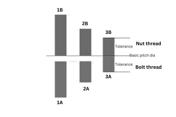
Tolerance: 2A threads maintain tighter tolerances compared to the more lenient 1A class, providing a precise fit without compromising on ease of assembly. The tighter tolerance also allows for better control over the dimensions of the thread, ensuring consistency and reducing the chances of fitting issues.

Fit: The 2A fit is a medium-tolerance fit, offering a balance between strength and ease of assembly. This makes 2A threads suitable for most general-purpose applications where both performance and convenience are important. Examples include automotive bolts, hydraulic connections, and general machinery fasteners.

By using UNF 2A threads, manufacturers can achieve a precise, stable connection while allowing for some minor flexibility to account for wear and variations in assembly conditions.

1A 2B 3B UNF Threads

B. Definition of UNF 2B (Internal Threads)

UNF 2B threads are designed for internal applications, such as nuts, tapped holes, and threaded inserts that receive external threads like those specified as 2A. Key characteristics of 2B threads include:

Allowance: 2B threads incorporate a slightly larger allowance than their external counterparts (2A), which provides a small gap between the mating threads. This design feature ensures that components can be easily assembled and adjusted without binding or seizing, even when there are slight imperfections or contaminants present.

Tolerance: The tolerance for 2B threads is greater compared to 2A threads to accommodate the additional clearance needed for ease of assembly. This makes 2B threads more forgiving during manufacturing and assembly, ensuring compatibility with a wide range of external threads.

Fit: The fit of 2B threads is designed to match perfectly with 2A external threads, creating a secure connection. However, due to the additional allowance, 2B threads are slightly looser than 2A, facilitating easy assembly and disassembly. This fit is ideal for most industrial applications, including fasteners, hydraulic systems, and other components where repeatability and ease of maintenance are crucial.

Overall, UNF 2B threads provide a reliable and adaptable solution for internal threading, especially in applications where the consistency of fit and ease of assembly are vital.

C. Historical Context

The development of Unified National Fine (UNF) threads originated as part of the Unified Thread Standard (UTS), established during World War II to standardize thread types across the United States, the United Kingdom, and Canada. The goal was to unify thread forms and pitches to facilitate interchangeability and reduce compatibility issues between different nations’ equipment.

The 2A and 2B thread classes were standardized as part of this system to provide a practical balance between precision and assembly ease:

UNF 2A threads were standardized for external applications, allowing for precision while maintaining some flexibility to ensure components could be assembled even if slightly imperfect or dirty.

UNF 2B threads were established to provide an internal match for 2A threads, with a slight allowance and greater tolerance to facilitate easy assembly and accommodate minor variances in manufacturing.

Key Differences Between UNF 2A and 2B Threads

A. Dimensional Differences

Pitch Diameter Variations: The pitch diameter, which is the diameter of an imaginary cylinder that passes through the thread profile where the width of the thread and the width of the space between threads are equal, varies slightly between 2A and 2B threads. For 2A (external) threads, the pitch diameter is smaller compared to 2B (internal) threads to account for the necessary clearance during assembly.

Allowance: UNF 2A threads incorporate a small allowance to ensure that external components can fit into internal threads without difficulty. This allowance is an intentional gap that ensures ease of assembly and disassembly. Conversely, 2B threads feature a larger allowance than their external counterparts to accommodate the external threads comfortably, even in conditions where there might be minor imperfections or variations.

Thread Height Differences: The thread height of external threads (2A) tends to be slightly shorter than that of internal threads (2B) to allow for the mating of the components without interference. This ensures that when an external 2A thread is assembled with a corresponding 2B internal thread, they fit together smoothly.

B. Tolerance and Fit

Tolerance Levels: The tolerance level for UNF 2A threads is tighter than that of UNF 2B threads. A tighter tolerance means that 2A threads are manufactured with precise control over dimensions, which is critical for external threads that need to align perfectly with the corresponding internal threads.

2B Thread Allowance: UNF 2B threads are designed with a greater allowance compared to 2A threads. This larger clearance makes the internal threads more accommodating when receiving external threads, reducing the likelihood of binding or difficulty during assembly. This is particularly beneficial in environments where external threads may be slightly worn or contaminated.

Impact on Fit: The looser fit of 2B threads is intended to make assembly easier and quicker, especially when dealing with large volumes of components or in environments where precision tooling might not always be available. On the other hand, the tighter fit of 2A threads provides better alignment and strength, which is essential for applications where secure and stable connections are critical.

C. Application-Specific Differences

Use Cases for 2A Threads (External):

Precision Components: In applications like automotive, aerospace, and hydraulic systems, where precise alignment is crucial for performance and safety, 2A threads are commonly used for bolts, screws, and other external components.

Load-Bearing Connections: For components that need to bear significant loads or are subject to dynamic forces, 2A threads provide the necessary precision and strength. This is especially important in structural or high-pressure systems where a secure fit is vital.

Situations Requiring Stability: In contexts where vibration or movement might cause loosening, the tighter fit of 2A threads helps maintain stability and reduces the risk of component failure.

Use Cases for 2B Threads (Internal):

General-Purpose Fasteners: 2B threads are widely used in nuts, tapped holes, and other internal threaded components for general applications. They provide a balance between precision and ease of assembly, making them suitable for mass-production environments where components must fit reliably with minimal adjustment.

Maintenance-Focused Environments: In situations where components need to be disassembled and reassembled frequently, such as in maintenance operations or field repairs, 2B threads provide the necessary allowance to facilitate easy, repeated use without damaging the threads.

Assembly Tolerance Requirements: 2B threads are preferred in cases where external threads might be subject to slight wear, dirt, or minor deformities. The greater tolerance and allowance of 2B threads ensure that assembly can still be achieved smoothly, even under less-than-ideal conditions.

D.Applications and Industries Using UNF 2A and 2B Threads

Automotive Industry

Precision Components: In the automotive industry, UNF 2A and 2B threads are commonly used for critical components such as engine parts, transmission systems, and chassis assemblies. The precise fit offered by these threads ensures that fasteners remain secure under high vibration and dynamic loads typical in vehicle operations.

Engine Assembly: UNF threads are often applied in engine blocks and cylinder heads where the need for precision and alignment is paramount. Bolts with 2A threads secure these components tightly to ensure no movement or displacement occurs during operation, while 2B threads are used in corresponding nuts or tapped holes to maintain stability and prevent leaks.

Suspension and Brake Systems: Fasteners with UNF threads are preferred in areas such as suspension systems and brake components, where precision and secure connections are necessary to maintain vehicle safety and performance.

Hydraulic Systems

Leak Prevention: In hydraulic systems, where fluid integrity is crucial, UNF threads (2A for fittings and 2B for ports or connectors) are often used to minimize leakage. The precise fit between these threads ensures that hydraulic connections are secure, reducing the risk of fluid escape that could lead to system failure.

Compatibility: Hydraulic components require consistent thread specifications to ensure compatibility between various parts like hoses, fittings, and valves. The use of standardized UNF 2A and 2B threads simplifies the design and assembly process, ensuring reliable and compatible connections across different parts of the system.

Durability in High-Pressure Applications: The precision offered by 2A threads is critical for components exposed to high pressure in hydraulic systems. The tighter fit prevents any shifting or loosening under pressure, maintaining system integrity and performance.

How to Identify and Measure UNF 2A and 2B Threads

A. Tools for Measurement

To accurately identify and measure UNF 2A (external) and 2B (internal) threads, it’s essential to use the right tools. These tools help verify the dimensions, pitch, and fit of threads to ensure they conform to specifications:

Calipers: Calipers are used to measure the diameter of the threads (major, minor, and pitch diameters). Digital calipers are recommended for precise measurements, especially when working with fine threads like UNF.

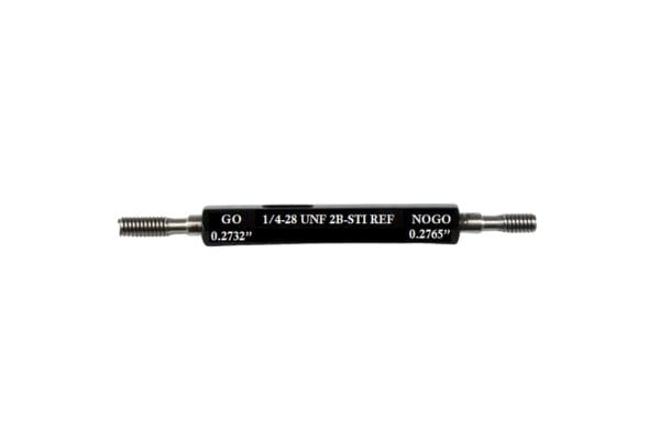
Thread Gauges: Thread gauges, also known as thread pitch gauges or thread checkers, are essential for determining the pitch of the threads. They come in various configurations for identifying both coarse (UNC) and fine (UNF) threads, and they help ensure that the pitch matches the specification (e.g., 16 threads per inch for 3/8″-16).

Micrometers: Micrometers offer a higher level of accuracy than calipers, particularly when measuring the pitch diameter. They are valuable for confirming the precise dimensions required for tight tolerance threads like UNF 2A and 2B.

Optical Comparator: In professional settings, an optical comparator can be used to visually inspect and compare the profile of the threads against a standard profile, ensuring conformity with specifications.

UNF 2A measure

B. Step-by-Step Guide to Measuring External (2A) and Internal (2B) Threads

Preparation:

Ensure the components being measured are clean and free of debris or oil, as contaminants can interfere with measurements.

Gather the necessary tools, such as calipers, thread gauges, and micrometers.

Measuring External Threads (2A):

Step 1: Measure the Major Diameter:

Use calipers to measure the major diameter (the outermost points) of the external thread. This gives you a preliminary measurement to confirm the size (e.g., 3/8″, 1/2″, etc.).

Step 2: Check the Pitch Using a Thread Gauge:

Align the appropriate thread gauge with the threads to confirm the pitch. Ensure it fits snugly along the thread’s profile, matching the number of threads per inch.

Step 3: Measure the Pitch Diameter with a Micrometer:

The pitch diameter is crucial for identifying UNF 2A threads accurately. Use a thread micrometer to measure the pitch diameter and confirm it falls within the specified tolerance for the class.

Step 4: Verify the Profile (Optional for precision settings):

Use an optical comparator to inspect the thread profile visually, ensuring the angle and shape conform to UNF standards.

Measuring Internal Threads (2B):

Step 1: Measure the Minor Diameter:

For internal threads, use calipers to measure the minor diameter (the innermost points) of the threads. This gives an initial indication of whether the internal thread matches the expected size.

Step 2: Verify the Pitch Using a Thread Gauge:

Insert the appropriate thread gauge into the internal threads to confirm the pitch. Make sure the gauge aligns with the thread without gaps or movement.

Step 3: Measure the Pitch Diameter with a Micrometer:

Use a micrometer or a specialized thread plug gauge to measure the pitch diameter of the internal threads. Ensure it falls within the tolerance range specified for 2B threads, which will have a slightly looser fit than 2A threads.

Step 4: Inspect the Thread Profile (Optional):

An optical comparator can also be used to inspect the profile of the internal threads if precise confirmation is needed, especially for critical applications.

UNF 2B measure

C. Common Mistakes to Avoid

Incorrect Gauge Selection:

One of the most common errors is using the wrong thread gauge for pitch measurement. Always ensure that the gauge corresponds to the UNF designation (e.g., 16 threads per inch for a 3/8″-16 UNF thread). Using an incorrect gauge can lead to misidentification.

Not Accounting for Wear:

Threads can wear over time, especially in high-use applications. When measuring older components, it’s crucial to consider wear and damage, as these can affect measurements. Check for deformation or flattening of threads before taking measurements.

Measuring Contaminated Threads:

Dust, oil, or other contaminants can interfere with accurate measurements. Always clean threads thoroughly before measuring to avoid inaccurate readings. In hydraulic or fluid system environments, it’s essential to use a degreaser or cleaning solution to remove all residues.

Ignoring Temperature Variations:

Measuring threads in environments with significant temperature fluctuations can result in dimensional changes. For the most accurate measurements, ensure that components are measured in a controlled environment where temperatures are stable, as metal expands or contracts with temperature changes.

Using Worn or Inaccurate Tools:

Ensure that tools like calipers, micrometers, and thread gauges are properly calibrated and not worn out. A worn tool can lead to incorrect readings, especially when measuring fine tolerances like those in UNF threads.

Best Practices for Choosing Between UNF 2A and 2B Threads

A. Factors to Consider

When selecting between UNF 2A and 2B threads, it’s crucial to evaluate several factors to ensure the best fit and functionality for your application:

Application Requirements:

Function and Load: Consider whether the component will bear significant loads or be subject to dynamic forces and vibrations. For load-bearing applications or those involving high precision, a tighter fit (2A external threads with 2B internal threads) ensures stability and security.

Ease of Assembly and Disassembly: If the application requires frequent assembly and disassembly, such as in maintenance scenarios or field repairs, 2B threads with a slightly larger allowance provide flexibility, making the process smoother.

Tolerance Requirements:

Precision: In industries like aerospace or hydraulics, where exact tolerances are critical to safety and performance, using threads with tighter tolerances (2A for external and 2B for internal) is essential. Evaluate whether the application demands precision over ease of assembly.

Fit Quality: Consider the fit quality needed. For applications where a more secure and tight fit is important, such as in fluid systems where leaks must be prevented, choosing 2A and 2B threads with precise matching tolerances helps maintain system integrity.

Material Compatibility:

Material Strength: Different materials (e.g., steel, aluminum, brass) have varying levels of strength and resistance to wear. Softer materials might require a more forgiving thread fit (2B) to accommodate slight deformities, while harder materials can maintain tighter tolerances without risk of damage.

Corrosion Resistance: For applications exposed to harsh environments (e.g., marine, chemical, or outdoor settings), materials with anti-corrosive properties should be chosen. Ensure that the material used for both the 2A and 2B threads is compatible to prevent galvanic corrosion and maintain a secure fit over time.

Environmental Conditions:

Temperature Extremes: If the components will be used in environments with high or low temperatures, metal expansion or contraction should be considered. Ensure that the chosen threads can maintain a secure fit under these conditions without risking loosening or deformation.

Exposure to Fluids or Chemicals: In hydraulic or chemical processing systems, selecting the appropriate thread fit and material (2A and 2B threads) helps prevent leaks and ensures the connection remains tight even under exposure to fluids. Use additional sealing techniques or thread coatings to enhance the connection’s durability.

UNF 2A vs 2B

B. Matching Threads for Optimal Performance

Properly pairing UNF 2A and 2B threads is essential for achieving a reliable and effective connection. Here are some best practices:

Ensuring Compatibility Between 2A and 2B Threads:

Always match external 2A threads with internal 2B threads to maintain the intended tolerance and allowance balance. This pairing is designed to provide a secure and tight fit while allowing for sufficient clearance during assembly.

Avoid pairing a 2A thread with an incorrectly sized internal thread class, as this can result in misalignment, improper fit, or potential damage to the threads during assembly.

Checking Thread Specifications:

Verify that the threads conform to the same specifications (e.g., 3/8″-16 UNF) to ensure they are compatible. Using mismatched thread sizes or pitches, even if they appear similar, can compromise the connection’s integrity and lead to failure.

Use thread gauges and calipers to confirm that both the 2A and 2B threads are within the specified tolerance range for the application.

Balancing Precision and Flexibility:

For applications where both precision and ease of assembly are important, such as in hydraulic systems, pairing 2A and 2B threads allows for a fit that is precise enough to prevent leaks while providing enough clearance to avoid binding during installation.

In cases where exact precision is less critical, such as non-load-bearing fasteners or components that need to be adjusted frequently, the looser fit of 2B threads can be advantageous for quicker and easier assembly.

Utilizing Thread Sealants and Lubricants:

For high-pressure systems or environments where leakage is a concern, using thread sealants (like PTFE tape or liquid thread sealant) ensures a leak-proof connection between 2A and 2B threads. This practice helps enhance the seal, especially in hydraulic or pneumatic applications.

In high-friction or corrosive environments, applying thread lubricants or anti-corrosive coatings can help maintain the integrity of the 2A and 2B threads, reducing wear and making disassembly easier when needed.

Ensuring Proper Alignment During Assembly:

Misalignment during assembly can cause cross-threading or damage, especially with precise 2A threads. Make sure that components are aligned correctly and that tools like torque wrenches are used when necessary to achieve the correct tension without over-tightening, which can distort the threads.

Common Issues and Troubleshooting Tips for UNF Threads

A. Thread Damage and Wear

Thread Galling:

Galling is a common issue with UNF threads, especially when metal surfaces rub against each other under high pressure or friction. It occurs when material from one thread surface transfers to another, causing seizing or jamming. Galling can be particularly problematic with softer metals like aluminum or stainless steel. It is often exacerbated when threads are assembled without proper lubrication.

Thread Wear:

Repeated use or frequent assembly and disassembly of components can cause threads to wear down over time. This can lead to a reduction in the effective pitch diameter, making it difficult for the threads to engage properly and resulting in loose or insecure connections.

Deformation:

Threads can become deformed due to over-tightening, cross-threading, or exposure to excessive loads. When a thread is over-torqued, it can become stretched or distorted, reducing its ability to maintain a secure fit. Cross-threading, where the threads are misaligned during assembly, can also cause significant damage and affect the integrity of the component.

Corrosion:

Exposure to corrosive environments or chemicals can weaken and degrade threads, especially if they are not treated or coated for corrosion resistance. Corroded threads are more likely to seize or become damaged during assembly and disassembly, compromising the connection.

B. Proper Maintenance Techniques

Regular Inspection:

Periodically inspect threaded components for signs of wear, deformation, or corrosion. Use magnification tools if necessary to detect minor defects or damage that might not be visible to the naked eye. For critical applications, consider implementing a routine inspection schedule to ensure threads remain in good condition.

Lubrication:

Apply a suitable thread lubricant or anti-seize compound before assembly to reduce friction, prevent galling, and protect against corrosion. Lubricants are particularly important when assembling UNF threads in high-temperature environments or when using materials prone to galling, such as stainless steel.

Thread Cleaning:

Before assembly, ensure threads are clean and free of debris, dust, or metal particles that could cause binding or wear. Use a wire brush or compressed air to clean threads thoroughly. In hydraulic or fluid systems, consider using a solvent-based cleaner to remove any residual oil or contaminants that might affect the seal.

Use of Protective Coatings:

In environments where threads are exposed to moisture, chemicals, or other corrosive elements, consider applying protective coatings, such as zinc plating or anodizing, to enhance corrosion resistance and extend the life of the threads.

Proper Torque Application:

Always use a torque wrench to apply the correct amount of torque as specified for the particular thread and application. Over-torquing can deform threads, while under-torquing may result in loose connections. For critical applications, consider using calibrated tools to ensure the correct torque values are consistently applied.

C. Troubleshooting Assembly Problems

Cross-Threading:

Problem: Cross-threading occurs when the external and internal threads are misaligned during assembly, causing the threads to engage incorrectly. This can result in damage or jamming.

Solution: To avoid cross-threading, start threading the component by hand and ensure it is aligned properly before using tools. If resistance is felt early in the threading process, stop immediately, back out the fastener, and realign it before trying again. Using thread guides or fixtures can help maintain proper alignment during assembly.

Thread Sizing:

Problem: Thread seizing, often caused by galling, happens when the threads lock together during assembly, making it difficult or impossible to turn the fastener.

Solution: Applying a high-quality lubricant or anti-seize compound to the threads before assembly can prevent seizing. If seizing does occur, apply a penetrating oil and allow it to soak before attempting to loosen the fastener. If threads are frequently seizing, consider using components made from materials less prone to galling, such as coated or treated metals.

Loose Connections:

Problem: Loose connections can occur if threads wear out, the wrong torque is applied, or if incompatible threads (e.g., mixing different classes) are used.

Solution: Verify that the thread classes (2A and 2B) match and that they are of the correct specification (e.g., 3/8″-16 UNF). Use a torque wrench to apply the appropriate torque value. If components frequently loosen due to vibration, consider using thread lockers or locking fasteners designed to maintain tension.

Thread Corrosion:

Problem: Corroded threads can become difficult to engage or disengage and may lead to thread damage if forced.

Solution: Inspect threads for signs of rust or corrosion before assembly. If corrosion is present, clean the threads thoroughly using a wire brush or rust remover. Apply anti-corrosion treatments or coatings to the threads for protection, and use stainless steel or treated materials if corrosion is a recurring issue in the environment.

Thread Deformation:

Problem: Threads that become deformed due to over-tightening or excessive load may not fit properly or may create weak connections.

Solution: If threads show signs of deformation, replace the affected components. To prevent future deformation, ensure the correct torque values are used and avoid over-tightening. Using torque-limiting tools or calibrated torque wrenches helps prevent damage.

Conclusion

Selecting the appropriate thread type is essential for achieving the best performance, durability, and safety in threaded connections. The right choice ensures compatibility, prevents issues such as cross-threading and leakage, and supports the specific needs of the application. Adherence to standards, such as matching 2A and 2B threads, is crucial to maintaining consistency and reliability across industries. Understanding the specific requirements of your application, including load-bearing capacity, environmental conditions, and precision needs, is key to making informed decisions and avoiding common thread-related problems.


FAQ

What is the difference between UNF 2A vs 2B threads?

UNF 2A threads are used for external applications such as bolts and screws, while UNF 2B threads are used for internal applications such as nuts and threaded holes. 2A threads are tighter, while 2B threads have more clearance for easier assembly.

Why choose UNF 2A threads?

2A threads provide a more precise fit for applications that require high precision and stability, such as critical components in the automotive and aerospace sectors.

What are the benefits of 2B threads?

UNF 2B threads have a larger clearance for applications that require frequent assembly and disassembly for easy maintenance and quick installation.

In which industries are UNF threads widely used?

UNF 2A and 2B threads are widely used in industries such as automotive, aerospace, hydraulics, as well as manufacturing and construction to ensure precise and reliable connections.

How can I prevent wear and damage to UNF threads?

Regular inspection, cleaning, and lubrication of threads can prevent wear and galling. Also, use proper torque tools to avoid over-tightening.

Can I mix 2A and 2B threads?

2A and 2B threads should be used in matched pairs as specified, with 2A used externally and 2B internally, to ensure optimal fit and performance and avoid compatibility issues.

Understanding UNF Threads banner

Understanding UNF Threads Standard: Choosing 1A, 2A, or 3A

Known for their fine pitch and precision, UNF threads offer increased tensile strength and are ideal for applications where vibration, pressure, or tight spaces require a secure and reliable connection. These threads are engineered to provide a strong hold while allowing for easy assembly and disassembly, making them a preferred choice in environments where precise adjustments are critical. UNF threads are designed to maximize performance, minimize the risks of loosening under stress, and ensure stability even in challenging conditions.

What are UNF Threads?

Definition and Background

Unified National Fine (UNF) threads are part of the Unified Thread Standard (UTS), which includes various thread forms commonly used across North America. The UNF designation specifically refers to threads with a fine pitch—meaning the distance between the thread crests is smaller compared to coarse threads like Unified National Coarse (UNC). The finer pitch of UNF threads allows for increased tensile strength and a more secure fit, making them particularly suited for precision applications where tight tolerances and secure connections are essential.

The origin of the Unified Thread Standard dates back to the early 20th century when the United States and Canada sought a unified system to standardize thread forms, ensuring interchangeability and consistency in manufacturing. This collaboration led to the creation of the Unified National Thread standard, which comprises UNF, UNC (Unified National Coarse), and other specialized variations like UNJF (Unified National Fine with a larger root radius). The standard aimed to harmonize thread types used in different industries, simplifying production and reducing compatibility issues.

Comparison to Other Thread Types (UNC, UNJF)

While UNF threads standard are characterized by their fine pitch, other thread types under the Unified Thread Standard have different purposes:

UNC (Unified National Coarse):

Thread Pitch: Coarser compared to UNF, resulting in fewer threads per inch.

Applications: Commonly used in general-purpose applications where strength and rapid assembly are required, such as in structural assemblies or less precise mechanical systems.

Key Differences: UNC threads are better for materials prone to thread stripping due to their larger root and more substantial structure. However, they lack the precision and tight fit offered by UNF threads, making them less suitable for high-pressure or vibration-prone environments.

UNJF (Unified National Fine with Increased Root Radius):

Thread Pitch: Similar to UNF, but with a larger root radius, which enhances fatigue resistance and reduces the risk of stress concentrations at the thread root.

Applications: Frequently used in critical aerospace and automotive applications where components experience high stress and require superior fatigue strength.

Key Differences: While both UNF and UNJF have fine pitches, UNJF’s larger root radius makes it more robust in high-stress environments. However, it also requires more precise manufacturing and assembly, leading to higher costs and more complex installation processes compared to standard UNF threads.

Overall, the primary distinction of UNF threads is their balance between pitch and strength, which allows for a secure fit suitable for a wide range of applications. While not as robust as UNJF threads, they provide enough precision for most hydraulic, automotive, and aerospace uses.

UNF vs UNJF Thread

Common Applications of UNF Threads

UNF threads are widely adopted in various industries due to their fine pitch and secure fit, which ensures stability and precision. Some common applications include:

Precision Hydraulic Fittings: UNF threads are frequently used in hydraulic systems, where maintaining a leak-free and secure connection is critical. The fine pitch allows for a tight seal, essential for preventing fluid leaks under high pressure.

Automotive Assemblies: In the automotive industry, UNF threads are utilized in components like brake fittings, engine parts, and suspension systems. Their fine pitch helps create strong, reliable connections in areas subject to vibration and movement, ensuring that parts remain securely fastened even under dynamic conditions.

Aerospace Components: Given their high strength-to-size ratio, UNF threads are a preferred choice in the aerospace sector. They are used in high-stress components such as aircraft fasteners, engine parts, and hydraulic systems, where weight reduction and reliability are crucial.

Industrial Machinery: UNF threads are also common in industrial equipment and machinery where precise assembly is required, and components must withstand high pressures or frequent adjustments without compromising system integrity.

The Three Classes of UNF Threads: 1A, 2A, and 3A

Overview of Thread Classes

Thread classes are essential in defining the level of tolerance and fit for threaded components. They determine how loose or tight a thread engagement will be, which directly influences the performance, reliability, and durability of the assembled components. In the context of UNF threads, the thread classes are categorized as 1A, 2A, and 3A for external threads. Each class offers varying levels of fit, with 1A being the loosest and 3A being the tightest.  

The proper selection of thread class is vital for achieving the desired performance, especially in systems where pressure, vibration, or thermal variations can affect the integrity of connections. Understanding the differences between the three classes of UNF threads allows engineers and technicians to make informed choices that balance ease of assembly, performance reliability, and cost-effectiveness.

UNF 1A Thread Class

Characteristics:

The UNF 1A thread class is designed with the loosest tolerance among the three UNF classes, offering the most flexibility during assembly. This loose tolerance allows for easy alignment and insertion, making it suitable for situations where components need to be rapidly assembled and disassembled. The loose fit also helps prevent cross-threading during the assembly process, reducing the risk of damage to the threads.

Applications:

UNF 1A threads are ideal for components that require frequent maintenance, adjustment, or replacement. Examples include machinery parts that need regular inspection, bolts used in temporary setups, and components in systems where quick assembly is prioritized. They are commonly found in low-pressure systems where precision is less critical, and convenience and speed are more important.

Advantages & Disadvantages:

Advantages: The primary benefit of the 1A class is its ease of assembly. The looser fit makes it less susceptible to cross-threading, and components can be assembled quickly, even in environments where precise alignment is challenging. This flexibility is advantageous for applications that prioritize maintenance accessibility.

Disadvantages: The downside of the 1A class is its lack of precision. Due to its loose tolerance, the connection is less secure and may not be suitable for high-pressure or high-vibration environments. Over time, the looser fit may also lead to issues such as loosening or thread wear, especially under stress.

UNF 2A Thread Class

Characteristics:

The UNF 2A thread class offers a medium tolerance level, making it the most commonly used and versatile thread class. It provides a balance between precision and ease of assembly, ensuring a secure fit while still allowing for relatively easy assembly and disassembly. This thread class is designed to fit general-purpose needs in a wide range of mechanical systems and is suitable for components that require moderate precision and reliability.

Applications:

UNF 2A threads are widely used in hydraulic and mechanical systems due to their versatility. They are suitable for components that need to maintain a secure fit under moderate pressure and vibration. Examples include hydraulic fittings, automotive fasteners, and general machinery components where a balance of reliability and ease of use is required. UNF 2A threads are often the standard choice for bolts, screws, and other fasteners in manufacturing and construction industries.

Advantages & Disadvantages:

Advantages: The 2A thread class strikes an ideal balance between assembly ease and connection reliability. Its medium tolerance provides a secure fit that can withstand moderate pressures and vibrations, making it suitable for various applications. The 2A class offers enough precision to ensure system integrity while still allowing for quick and efficient assembly.

Disadvantages: While the 2A class is versatile, it may not be precise enough for high-pressure or safety-critical applications that require the utmost accuracy. It may also require periodic checks and maintenance in environments where extreme conditions could lead to loosening or wear over time.

1A 2B 3B UNF Threads

UNF 3A Thread Class

Characteristics:

The UNF 3A thread class is designed with the tightest tolerance of the three classes, offering the highest level of precision and fit. This tight tolerance ensures a very secure connection, making it ideal for applications where even the slightest movement or loosening could lead to system failure. The 3A thread class requires careful alignment during assembly due to its tighter fit, which demands greater precision.

Applications:

UNF 3A threads are typically used in critical systems where a highly secure and stable connection is essential. They are often found in high-pressure hydraulic systems, aerospace components, and safety-critical parts where failure is not an option. In such environments, the secure fit provided by the 3A thread class minimizes the risk of leaks, loosening, or failures under stress. These threads are also used in applications that experience extreme vibrations or thermal variations, where maintaining system integrity is paramount.

Advantages & Disadvantages:

Advantages: The primary advantage of the 3A thread class is its precision and reliability. The tight fit ensures a secure, leak-free connection, making it ideal for high-stakes and high-performance environments. The 3A class is particularly beneficial when long-term stability and safety are critical, as it minimizes the risk of thread failure under stress or vibration.

Disadvantages: The 3A thread class’s high precision comes at the cost of ease of assembly. Due to its tight tolerance, it requires careful alignment during installation, making the assembly process more challenging and time-consuming. This also increases the likelihood of cross-threading if not assembled with precision, potentially leading to component damage. Additionally, components with 3A threads may have higher manufacturing and maintenance costs, as they require stricter quality control and periodic checks to maintain their tight fit.

Tolerance Levels and Fit in UNF Threads

Understanding Tolerance and Fit

Tolerance refers to the allowable variation in the dimensions of a thread, specifically the degree of tightness or looseness in the connection between mating components. In thread manufacturing, tolerance levels determine how closely the threads on bolts, screws, and other fasteners align with their corresponding nuts or fittings. A higher tolerance level (looser fit) allows for easier assembly and flexibility, while a lower tolerance level (tighter fit) requires more precision but provides a more secure and stable connection.

The fit between threaded components affects the overall performance, alignment, and stability of mechanical systems. For example, loose-fitting threads may be beneficial for quick assembly or when frequent disassembly is needed, but they may not hold up under high pressure or vibration. Conversely, tight-fitting threads offer superior strength and stability but may require careful alignment during assembly to prevent damage and ensure a proper fit. The appropriate tolerance level must be chosen based on the application requirements, including load conditions, environmental factors, and the frequency of assembly or maintenance.

Comparative Analysis: 1A vs. 2A vs. 3A

Each UNF thread class—1A, 2A, and 3A—has a distinct tolerance level that affects its fit and, consequently, its suitability for different applications:

UNF 1A (Loose Tolerance):

The 1A class has the loosest tolerance among the UNF thread classes, making it the most flexible option. The loose fit allows for easy assembly, particularly in scenarios where components need to be quickly put together or taken apart. This flexibility reduces the risk of cross-threading and facilitates fast installation, even when precise alignment is not possible. However, this looser tolerance also means that 1A threads are less secure, and the connection may be prone to movement or loosening under stress, pressure, or vibration.

Application: The 1A class is best suited for low-pressure, low-vibration environments where quick assembly and disassembly are needed, such as temporary fixtures or frequently adjusted machinery.

UNF 2A (Medium Tolerance):

The 2A class offers a medium tolerance level, balancing the ease of assembly with a secure fit. As the most common UNF thread class, 2A threads provide a moderate level of precision, making them versatile enough for general-purpose applications. The tighter fit compared to the 1A class ensures that the connection remains stable under moderate pressure and vibration, while still allowing for relatively quick assembly and disassembly. The 2A class is the standard choice for most hydraulic and mechanical systems because it offers a reliable fit without the need for high-precision alignment.

Application: UNF 2A threads are typically used in hydraulic fittings, automotive assemblies, and industrial machinery components where a balance between precision and ease of use is necessary.

UNF 3A (Tight Tolerance):

The 3A class has the tightest tolerance among the UNF threads, providing the most secure and precise fit. This tight tolerance level minimizes movement and ensures a strong, stable connection, making 3A threads ideal for high-pressure systems, critical components, and environments subject to extreme vibration. However, the tight fit requires precise alignment during assembly, making the process more challenging and time-consuming. Additionally, due to their precision, 3A threads are often more costly to manufacture and maintain, as they need strict quality control to achieve the required specifications.

Application: UNF 3A threads are most suitable for aerospace components, high-pressure hydraulic systems, and other safety-critical applications where even slight loosening or movement could lead to system failure.

Factors to Consider When Choosing the Right Thread Class

When selecting the appropriate UNF thread class—1A, 2A, or 3A—there are several key factors to consider. Each class offers different tolerance levels that influence its suitability based on the application’s specific requirements, the environment in which it will operate, the frequency of assembly, and the materials used.

Application Type and Environment

The environment in which a threaded component operates plays a critical role in determining the appropriate thread class. Factors such as vibration, temperature extremes, pressure levels, and exposure to corrosive substances directly impact the performance and longevity of threads.

Vibration:

Applications that involve high levels of vibration, such as those found in automotive engines or industrial machinery, require a secure and stable connection. In such cases, UNF 3A threads, with their tightest tolerance, are ideal because they minimize the risk of loosening under vibration. Conversely, UNF 1A threads, with their loose fit, may not provide the necessary stability, making them unsuitable for these environments.

For moderate vibration levels, UNF 2A threads strike a balance, providing enough stability while still being easier to assemble and adjust.

Temperature Extremes:

Extreme temperatures can cause the expansion and contraction of materials, potentially affecting thread integrity. In high-temperature environments, such as those encountered in aerospace or heavy machinery, UNF 3A threads are preferred due to their precision and ability to maintain a secure fit even when materials expand. Low-tolerance threads like 1A may loosen under temperature changes, leading to failures.

For applications where temperature variations are moderate and do not critically affect material expansion, 2A threads can offer a practical solution without the need for the precision of 3A.

Pressure Levels:

High-pressure systems, especially those found in hydraulic applications, demand tight and secure connections to prevent leaks and maintain operational integrity. UNF 3A threads are particularly suitable for these high-pressure environments, as their precise fit ensures a leak-proof seal. In contrast, for low-pressure applications where the risk of leakage is minimal, UNF 1A threads may be adequate due to their ease of assembly.

Systems with moderate pressure requirements can benefit from 2A threads, as they provide a stable fit without the complexity and cost associated with 3A threads.

Corrosive and Hazardous Environments:

In environments exposed to corrosive agents or hazardous substances, such as chemical processing plants, thread integrity is paramount. The secure fit of UNF 3A threads can help prevent leaks that might lead to contamination or exposure. For less demanding environments, 2A threads can suffice, while 1A threads may be avoided if the risk of exposure or leakage poses safety concerns.

Assembly Frequency

The frequency of assembly and disassembly is another crucial consideration when choosing a thread class. Different applications require varying levels of ease and precision during assembly, directly influencing which class is most appropriate.

Frequent Assembly and Disassembly:

When components need to be assembled and disassembled regularly, as seen in maintenance-heavy systems or temporary setups, UNF 1A threads are the most suitable. Their loose tolerance allows for quick assembly without the need for precise alignment, minimizing the risk of cross-threading or damage. For example, bolts used in machinery that undergo frequent inspections or part replacements benefit from the ease of use provided by 1A threads.

Moderate Assembly Frequency:

Applications that require occasional assembly but still demand a secure fit benefit from UNF 2A threads. These threads provide enough precision to ensure stability while remaining easy to assemble and disassemble when necessary. Hydraulic systems, for instance, often use 2A threads for fittings that need to be adjusted or replaced during maintenance but must also maintain a reliable seal when in operation.

Permanent or Static Setups:

For components that are assembled once and are not intended to be frequently adjusted, such as structural components in aerospace or critical hydraulic fittings, UNF 3A threads are the best choice. Their tight tolerance ensures a strong, stable fit that remains secure over long periods, even under stress. The added precision, while making assembly more challenging, is justified by the need for a permanent, leak-free connection.

Precision Requirements

Precision is a key determinant in selecting a thread class, particularly in applications where even the smallest deviations can have significant consequences. High-precision environments, such as aerospace and medical device manufacturing, often require the use of UNF 3A threads.

Critical Applications:

In aerospace systems, where precision and stability are vital for safety, UNF 3A threads are commonly used for components such as fasteners, fittings, and other critical parts. The high precision of 3A threads minimizes the risk of component movement, ensuring that connections remain tight and stable under various stress conditions, such as high speeds, extreme temperatures, or vibrations.

Standard Precision Needs:

For applications with moderate precision requirements, like automotive assemblies or general machinery, UNF 2A threads are ideal. They provide a balance between ease of assembly and precision, making them versatile for components that need a secure fit but do not experience the extreme conditions seen in aerospace systems.

UNF and UNC

Material Compatibility

The interaction between materials is another crucial factor when selecting a thread class. Different materials can behave differently when threaded, especially under high-tolerance conditions like those of UNF 3A.

Avoiding Galling:

Galling, a form of wear caused by adhesion between sliding surfaces, is a concern when using high-tolerance threads, particularly with softer metals like aluminum or stainless steel. In applications involving these metals, using 3A threads may require additional precautions, such as using anti-seize lubricants or coatings, to prevent thread damage during assembly.

For softer metals, UNF 2A or 1A threads might be preferable, as their looser tolerances reduce the risk of galling. However, engineers must weigh this against the need for precision and stability.

Hard vs. Soft Material Pairings:

When pairing hard materials (e.g., hardened steel) with softer ones (e.g., aluminum), the choice of thread class must account for the difference in wear characteristics. For instance, 3A threads, with their tight tolerance, may be used if the softer material is coated or treated to withstand the pressure. Alternatively, using 2A threads can offer a compromise, providing enough fit precision without excessive stress on softer components.

Corrosion Resistance and Material Choices:

In corrosive environments, selecting the right material and thread class combination is vital. For stainless steel fittings in marine or chemical applications, choosing a 3A class may be essential to prevent leaks and maintain integrity. However, ensuring that the thread surfaces are treated or lubricated appropriately can extend the life of both the threads and the fittings.

Conclusion

Understanding these differences is crucial for making informed decisions when selecting thread classes. Choosing the correct UNF thread class directly impacts system performance, reliability, and safety. An incorrect choice can lead to leaks, loose connections, or even system failures, especially in high-pressure or high-vibration environments. Selecting the appropriate thread class based on the application, environment, and precision requirements ensures that components remain securely fastened, maintaining the efficiency and safety of the overall system.


FAQ

What are UNF threads?

UNF (Unified National Fine) threads are a type of thread with a fine pitch used for secure, precise connections in various applications, including hydraulics, automotive, and aerospace.

What is the difference between UNF 1A, 2A, and 3A threads?

UNF 1A threads have the loosest tolerance for easy assembly, 2A threads provide a balanced fit for general use, and 3A threads have the tightest tolerance for high-precision applications.

When should I use UNF 1A threads?

Use UNF 1A threads when components need frequent assembly and disassembly, as they offer flexibility and easy alignment, suitable for non-critical, low-pressure environments.

Why are UNF 2A threads the most common choice?

UNF 2A threads are the most versatile, offering a balanced fit that ensures both ease of assembly and a secure connection, making them ideal for most hydraulic and automotive applications.

In which situations are UNF 3A threads best used?

UNF 3A threads are ideal for high-pressure or high-vibration applications where precision and a tight fit are critical, such as in aerospace components and critical hydraulic systems.

How do I choose the right UNF thread class for my application?

Consider the application’s environment, the frequency of assembly, and the precision required. For guidance, consult professionals or industry experts to ensure the best fit for your system’s needs.

SAE J1926-1 vs ISO 11926-1 banner

SAE J1926-1 vs ISO 11926-1: Key Differences Explained

Hydraulic fitting standards are fundamental in ensuring seamless operation, safety, and efficiency within fluid power systems. SAE J1926-1, predominantly used in North America, utilizes UN/UNF threads coupled with O-ring sealing to secure connections and prevent leakage. On the other hand, ISO 11926-1, widely adopted globally, especially in Europe, employs metric threads, aligning with international standards to support global equipment compatibility.

Overview of SAE J1926-1 and ISO 11926-1

SAE J1926-1

Origin and Development:

The SAE J1926-1 standard, formulated by the Society of Automotive Engineers (SAE), has become a critical specification for hydraulic port fittings, particularly in North America. The standard was created to provide uniformity and reliability in hydraulic systems, focusing on industries such as mobile machinery and industrial applications where consistent and high-performing connections are crucial.

Purpose and Applications:

SAE J1926-1 emphasizes hydraulic port threads and O-ring sealing mechanisms, ensuring secure, leak-proof connections. Its application is prevalent in sectors like construction, agriculture, and heavy equipment manufacturing, where robust and reliable hydraulic systems are essential. While its primary adoption is in North America, the standard’s compatibility with other international systems has led to its use in various global regions. By utilizing UN/UNF threads that align with ASME B1.1 specifications, SAE J1926-1 promotes integration and compatibility with existing systems.

Key Characteristics:

Thread Type: The use of UN/UNF threads, compliant with ASME B1.1, provides a precise, uniform threading structure that ensures compatibility and ease of installation.

Pressure Rating: The fittings are designed to perform under high-pressure conditions, offering durability and safety in demanding environments. This high-pressure tolerance makes them suitable for heavy-duty applications such as construction equipment and hydraulic presses.

Materials: SAE J1926-1 fittings commonly use carbon steel and stainless steel. Carbon steel offers an economical option for general applications, while stainless steel provides superior corrosion resistance for harsher conditions or where higher durability is needed.

SAE J1926-1

ISO 11926-1

Development and Role:

ISO 11926-1 was established by the International Organization for Standardization (ISO) as a global equivalent to SAE J1926-1. The aim was to provide an internationally consistent specification that caters to hydraulic systems operating in diverse environments and industrial settings. Developed with global use in mind, it aligns with the metric system, supporting international machinery and equipment compatibility, particularly in Europe.

Usage and Adoption:

ISO 11926-1 is extensively adopted in Europe and many international markets where metric systems dominate. By offering standardized fitting dimensions, the standard ensures that hydraulic components can be easily integrated into various systems worldwide, reducing trade barriers and minimizing compatibility challenges. The goal is to streamline global manufacturing and maintenance processes by providing a unified standard that different regions can adopt without modification.

Key Features:

Thread Type: The standard uses metric threads as outlined in ISO 725. This aligns it with metric-based hydraulic systems, enhancing compatibility with international machinery.

Compatibility: ISO 11926-1 was developed to be versatile and adaptable across global applications. It supports systems requiring a broad range of hydraulic setups, making it suitable for manufacturers and operators involved in international trade.

Materials: The fittings often incorporate high-resistance materials like stainless steel, which provide excellent corrosion resistance and longevity, crucial for equipment operating in varied and harsh environments. This use of durable materials helps ensure that hydraulic systems remain efficient and reliable under a variety of conditions, from agricultural equipment in humid climates to industrial machinery exposed to corrosive substances.

Thread Design and Sealing Mechanism

The thread design and sealing mechanism are crucial elements that distinguish SAE J1926-1 from ISO 11926-1. Understanding these differences is essential for ensuring system compatibility, avoiding leaks, and maintaining optimal hydraulic performance.

Comparison of Thread Designs Used in SAE J1926-1 and ISO 11926-1

SAE J1926-1 Thread Design:

SAE J1926-1 uses UN/UNF threads, which are based on the ASME B1.1 standards. UN (Unified National) threads have a 60-degree thread angle, and UNF (Unified National Fine) variants have finer pitches, making them ideal for precise, high-pressure hydraulic applications. These threads are prevalent in North American hydraulic systems due to their consistency and ease of integration. The thread profiles and dimensions ensure a secure fit when paired with complementary components, promoting leak-free connections.

UN/UNF Thread Features:

Unified Thread Series: Allows interchangeability with other UN-threaded components, streamlining assembly and maintenance.

Fine Thread Pitch: UNF threads provide greater surface contact, enhancing grip and reducing the risk of loosening under pressure.

Compatibility: Compatible with various North American fittings and commonly used for hydraulic ports and stud ends.

ISO 11926-1 Thread Design:

ISO 11926-1, on the other hand, specifies metric threads as per ISO 725 standards. These threads have a 60-degree thread angle like UN threads, but the thread pitch and dimensions differ, aligning with metric system requirements. Metric threads are prevalent in European and international markets where machinery and equipment often follow metric specifications.

Metric Thread Features:

ISO 725 Standards: Ensure consistency and uniformity for hydraulic applications using metric systems.

Flexibility: Available in various pitches and diameters, offering flexibility for different equipment designs.

Global Compatibility: Facilitates integration into systems operating in international environments, making ISO 11926-1 fittings versatile and suitable for global markets.

Sealing Mechanisms

Both SAE J1926-1 and ISO 11926-1 employ O-ring sealing, but the design and implementation differ due to their thread systems and regional requirements. The O-ring serves as a crucial component to prevent fluid leakage and maintain pressure within hydraulic systems.

O-Ring Groove Design Differences and Sealing Efficiency:

SAE J1926-1: The O-ring groove in SAE J1926-1 is designed to fit the dimensions of UN/UNF threads. It ensures a snug fit that compresses the O-ring when the fitting is tightened, creating an effective seal. The placement and dimensions of the groove are optimized for the thread profile, enhancing the sealing capability under high-pressure conditions commonly encountered in mobile and industrial hydraulic systems.

ISO 11926-1: In ISO 11926-1, the O-ring groove is designed according to metric thread profiles, as outlined in ISO 725 standards. The dimensions and positioning of the groove are adjusted to accommodate the different pitch and diameter of metric threads. This design also aims for optimal compression of the O-ring, providing a leak-proof seal that meets international hydraulic performance standards.

The efficiency of these sealing mechanisms depends on the precise match between the O-ring and the groove. If the O-ring is not properly seated or if the groove dimensions are off, even slightly, it can lead to improper compression, which may cause leaks and reduce the effectiveness of the hydraulic system.

Importance of Correct Thread Engagement for Leak Prevention

Ensuring correct thread engagement is critical to maintaining a secure, leak-free connection in hydraulic systems. Here’s why:

Proper Alignment: Accurate thread engagement allows for the correct alignment of the fitting components, which is essential for the O-ring to sit perfectly in its groove. Misalignment can distort the O-ring, reducing its sealing effectiveness and increasing the likelihood of leaks.

Thread Tightening and Torque Control: Proper tightening of the fitting, according to the specifications of SAE J1926-1 or ISO 11926-1, is vital. Over-tightening or under-tightening can damage the threads and the O-ring, compromising the seal and causing potential leakage. Each standard provides guidelines on torque values to ensure correct compression without damaging the components.

Thread Lubrication and Preparation: In both standards, preparing the threads by cleaning and lubricating them with appropriate hydraulic oil or thread lubricant is recommended. This reduces friction during installation and ensures smoother engagement, helping achieve the precise compression required for the O-ring to function effectively.

Compatibility and Interchangeability

Hydraulic systems often require a mix of components that adhere to various standards due to differences in regional preferences or equipment origins. SAE J1926-1 and ISO 11926-1 represent two such standards, commonly found in international markets.

Interchangeability of SAE and ISO Standards in International Markets

SAE J1926-1 and ISO 11926-1 are both widely accepted in the global hydraulic market, but their interchangeability is limited due to differences in thread types and dimensions. SAE J1926-1 is prevalent in North America and regions influenced by North American industrial standards, utilizing UN/UNF threads that align with ASME B1.1. ISO 11926-1, on the other hand, is widely adopted internationally, particularly in Europe, and uses metric threads compliant with ISO 725 standards.

Regional Influence: In North America, most hydraulic systems are built according to SAE standards, making SAE J1926-1 fittings the default choice. In contrast, European and other international markets often favor ISO standards, thus ISO 11926-1 fittings are more commonly available.

Global Trade Considerations: Manufacturers operating internationally may encounter a mix of machinery adhering to both SAE and ISO standards, especially if the equipment is sourced from different regions. This necessitates understanding and working with both standards for seamless integration and maintenance.

ISO 11926-1

Potential Compatibility Challenges When Mixing Fittings

While both SAE J1926-1 and ISO 11926-1 standards use O-ring sealing for hydraulic connections, the thread profiles and dimensions differ significantly, creating several compatibility challenges when mixing fittings from these standards:

Thread Type Mismatch: SAE J1926-1 uses UN/UNF threads with unified dimensions, while ISO 11926-1 uses metric threads with a different pitch and diameter profile. Attempting to connect these two directly would result in improper thread engagement, leading to a loose connection or complete failure.

O-Ring and Groove Design Differences: Even though both standards employ O-ring sealing, the groove dimensions for accommodating these O-rings differ due to thread variations. This means that even if a makeshift connection is achieved, the O-ring may not seal effectively, increasing the risk of leaks.

Dimensional Inconsistencies: The fittings’ outer diameters and lengths vary between SAE and ISO specifications. These differences can lead to issues when assembling components, such as misalignment or difficulties in positioning fittings correctly, particularly in complex systems where spatial constraints are critical.

Pressure Ratings and Application Differences

Hydraulic systems rely heavily on the pressure ratings of their components to maintain efficiency and safety. SAE J1926-1 vs ISO 11926-1 standards, while both designed for high-pressure hydraulic applications, differ slightly in their pressure ratings and the specific environments where they are most commonly applied.  

Pressure Rating Differences Between the Two Standards

SAE J1926-1 Pressure Ratings:

SAE J1926-1 fittings are engineered to meet the demands of high-pressure hydraulic systems, which are prevalent in North American industries such as agriculture, construction, and heavy machinery. These fittings generally have robust pressure tolerances, often ranging from 3000 psi to upwards of 6000 psi, depending on the fitting type, material, and application. The standard defines specific thread sizes and dimensions to ensure these pressure levels are consistently achievable and safe across various hydraulic setups.

ISO 11926-1 Pressure Ratings:

ISO 11926-1 also supports high-pressure applications but uses metric thread dimensions, adhering to ISO 725 standards. This standard is optimized for international hydraulic systems, particularly those prevalent in Europe and other regions where metric units are the norm. ISO fittings typically offer similar pressure capabilities to their SAE counterparts, with ratings also ranging from 3000 psi to 6000 psi. However, variations in thread design and material specifications between SAE and ISO fittings may result in slight differences in pressure tolerance, particularly when choosing materials like carbon or stainless steel for specific applications.

Typical Applications for Each Standard

SAE J1926-1 Applications:

Mobile and Industrial Hydraulics: In North America, SAE J1926-1 is a standard choice for mobile hydraulic systems, such as those found in construction machinery (e.g., excavators, loaders) and agricultural equipment (e.g., tractors). The standard’s widespread usage in these industries ensures that fittings and components are readily available and compatible with existing equipment.

Heavy-Duty Machinery: Industrial applications, including manufacturing plants and hydraulic presses, also favor SAE J1926-1 for its proven reliability under high-pressure conditions. The standard is designed to withstand the rugged environments often encountered in these industries, making it a trusted choice for maintaining system integrity and performance.

ISO 11926-1 Applications:

International and European Systems: ISO 11926-1 fittings are predominantly used in European markets and other international regions where metric units are standard. Industries such as automotive manufacturing, renewable energy, and industrial automation frequently use ISO fittings to maintain compatibility and meet regulatory requirements.

Versatile Hydraulic Systems: ISO fittings are preferred in hydraulic systems designed for global deployment, allowing for equipment interchangeability across different regions. They are suitable for varied applications, from factory automation systems to offshore drilling platforms, where international standards are a requirement for safety and compatibility.

Material Specifications and Corrosion Resistance

The material specifications for hydraulic fittings are essential for ensuring durability, safety, and compatibility under various environmental conditions. SAE J1926-1 and ISO 11926-1 specify different material standards, each designed to suit their respective applications and regional requirements.  

Comparison of Material Standards for SAE J1926-1 vs ISO 11926-1

SAE J1926-1 Material Standards:

SAE J1926-1 fittings commonly use carbon steel and stainless steel, providing a balance between strength, cost, and corrosion resistance. These materials are chosen based on their ability to withstand high-pressure applications and the demanding environments encountered in mobile and industrial hydraulics. The standard defines specific requirements for these materials to ensure uniformity and reliability across different systems.

ISO 11926-1 Material Standards:

ISO 11926-1 also specifies the use of high-strength materials like stainless steel and carbon steel, particularly for international and European markets where equipment might face diverse environmental conditions. The standard emphasizes corrosion-resistant materials to support hydraulic systems that must operate globally, often in areas with varying humidity levels, salt exposure, or corrosive chemicals.

While both standards often use similar materials, the specifications and manufacturing processes may vary slightly due to differences in regional regulations and environmental expectations. For instance, ISO standards may have stricter guidelines for material testing to ensure global applicability.

Discussion on Material Options

Stainless Steel:

Characteristics: Stainless steel is prized for its high corrosion resistance, making it ideal for hydraulic systems exposed to harsh environments, including marine, chemical processing, or coastal areas where humidity and salt can lead to accelerated corrosion.

Suitability: Hydraulic systems that face frequent exposure to moisture, chemicals, or salt (such as offshore drilling equipment or food processing machinery) greatly benefit from using stainless steel fittings. It offers longevity and requires less maintenance compared to carbon steel.

ISO vs. SAE: Both ISO 11926-1 and SAE J1926-1 accommodate stainless steel as an option, but ISO applications, especially in Europe, often favor it due to stricter environmental standards and regulations.

Carbon Steel:

Characteristics: Carbon steel is a widely used, cost-effective material that provides sufficient strength for high-pressure hydraulic applications. However, its susceptibility to rust when exposed to moisture or corrosive agents means it must often be coated or treated for enhanced durability.

Suitability: It is suitable for hydraulic systems operating in less corrosive environments or where cost management is a priority. Applications like construction machinery, agricultural equipment, and other mobile hydraulic systems typically use carbon steel components with protective coatings.

ISO vs. SAE: While both standards allow carbon steel, SAE J1926-1 frequently utilizes this material for North American markets where environmental conditions may not be as severe. Protective treatments, such as zinc plating or phosphate coatings, are commonly applied to extend the lifespan of carbon steel components.

Corrosion Resistance Properties and Best Practices for Maintenance

Corrosion Resistance Properties:

Stainless Steel: Stainless steel offers inherent corrosion resistance due to its chromium content, which forms a protective oxide layer on the surface. This layer acts as a barrier against oxidation, preventing rust and maintaining the fitting’s integrity. It’s an excellent choice for environments where hydraulic systems encounter salt water, chemicals, or high humidity.

Carbon Steel with Coatings: Carbon steel’s corrosion resistance can be improved by applying zinc, phosphate, or other protective coatings. These coatings create a barrier that shields the metal from exposure to moisture and corrosive substances. However, over time, these coatings may wear off, necessitating reapplication or replacement of the fittings.

Best Practices for Maintenance:

Regular Inspections: Hydraulic fittings should be inspected regularly for signs of corrosion, particularly if carbon steel is used. Look for rust, discoloration, or surface pitting, which may indicate that the protective coating has worn off. Stainless steel fittings should also be monitored for damage that could compromise their corrosion-resistant layer.

Proper Storage: When not in use, fittings should be stored in a dry, controlled environment to minimize exposure to moisture and contaminants. Carbon steel components, in particular, benefit from storage in low-humidity areas to prevent rust formation.

Use of Anti-Corrosive Treatments: For carbon steel components, applying anti-corrosive sprays or lubricants can enhance their resistance to moisture. These treatments help maintain the integrity of the fittings, especially for systems exposed to challenging outdoor or industrial conditions.

Conclusion

When choosing the appropriate standard, consider the region where the equipment will operate and whether it aligns with local industry preferences. For applications requiring global compatibility, ISO 11926-1 may be advantageous. Conversely, SAE J1926-1 is ideal for North American systems. Consulting experts is crucial when integrating or adapting components from different standards to avoid compatibility issues and ensure system safety.


FAQ

What is the main difference between SAE J1926-1 and ISO 11926-1?

The primary difference is the thread type: SAE J1926-1 uses UN/UNF threads, while ISO 11926-1 uses metric threads.

Where is SAE J1926-1 most commonly used?

SAE J1926-1 is primarily used in North America, especially in mobile and industrial hydraulic systems.

Which regions commonly use ISO 11926-1 fittings?

ISO 11926-1 fittings are widely used in Europe and other international markets where metric standards prevail.

Can SAE and ISO fittings be used interchangeably?

No, due to differences in thread type and dimensions, SAE and ISO fittings are not directly interchangeable.

What materials are typically used for SAE J1926-1 fittings?

SAE J1926-1 fittings are often made of carbon steel or stainless steel, depending on the application.

Why is consulting an expert important when mixing fittings from different standards?

Consulting an expert ensures the correct use of adapters and proper sealing techniques, preventing leaks and compatibility issues.

R vs Rc Threads banner

R vs Rc Threads: What You Need to Know

R and Rc threads are essential components in hydraulic and pneumatic systems, providing secure and pressure-tight connections in various applications. Known for their tapered design, these threads are commonly used in industries that require precise and reliable sealing mechanisms. R threads refer to the male tapered threads, while Rc threads represent their female counterparts, working together to create efficient connections that maintain system integrity under high-pressure conditions.

Understanding R and Rc Threads

Definition of R Threads

R threads are a type of tapered male thread similar to BSPT (British Standard Pipe Taper) threads. They are specifically designed to create a pressure-tight seal as the male thread tightens into a corresponding female thread (Rc). The taper angle of R threads ensures that as they are screwed into a fitting, the diameter gradually decreases, allowing for a tight, secure fit that becomes stronger with additional torque. This tapering is what differentiates them from parallel threads, which maintain the same diameter along their length.

Characteristics of R Threads:

Tapered Design: The tapering of R threads helps in forming a secure, pressure-tight seal without the need for additional sealing components like O-rings or bonded washers, although sealing tape (e.g., PTFE) may be used for added security.

Self-Sealing Nature: Due to the tapered design, R threads can create a seal by tightening alone, which is advantageous in high-pressure hydraulic systems where reliability is critical.

Common Standards: R threads follow international standards, such as ISO 7-1 or EN 10226-1, ensuring consistency in dimensions and compatibility.

Applications of R Threads in Hydraulic Systems:

High-Pressure Fittings: R threads are commonly used in high-pressure hydraulic applications, such as hoses, pumps, and valves, where secure connections are vital for safety and performance.

Fluid Transfer Lines: They are also utilized in systems where fluids are transported under pressure, ensuring that the connections remain leak-proof even under high stress.

Industrial Equipment: R threads are often found in various industrial equipment setups, including machinery and manufacturing systems that rely on hydraulic and pneumatic power.

BSP Threads

Definition of Rc Threads

Rc threads are the female counterpart to R threads and share the same tapered design. As the female version, Rc threads are engineered to perfectly match the male R threads, creating a secure fit when they are tightened together. This complementary nature is essential for the effectiveness of hydraulic and pneumatic connections.

Characteristics of Rc Threads:

Tapered Female Design: Rc threads feature a taper that matches the male R thread’s taper angle, allowing for a precise and secure fit when connected. This ensures that pressure applied within the system does not cause leakage at the thread connection points.

Standardization: Like R threads, Rc threads adhere to international standards (ISO 7-1 or EN 10226-1), which define the dimensions, taper angles, and tolerances necessary for compatibility and reliability.

Sealing Capability: Rc threads contribute to the sealing capability of the connection when paired with R threads, creating a unified and leak-proof system without requiring additional sealing elements, although PTFE tape can be applied for reinforcement.

Typical Uses of Rc Threads in Pneumatic and Hydraulic Systems:

Hydraulic Couplings: Rc threads are widely used in hydraulic couplings, where male R threads connect to female Rc threads to form robust, pressure-resistant fittings.

Pneumatic Equipment: In pneumatic systems, Rc threads are utilized in components like valves, actuators, and air compressors, ensuring tight connections that prevent air leaks and maintain system efficiency.

General Pipework: Rc threads are also found in general industrial pipework and plumbing applications where a durable, pressure-sealed connection is necessary.

R vs Rc Threads Overview

The fundamental difference between R and Rc threads lies in their designation as male and female threads. While both threads are tapered, R threads (male) and Rc threads (female) are designed to be used together to form a tight and secure connection in hydraulic and pneumatic systems.

How They Work Together:

Complementary Design: The male R thread fits into the female Rc thread, with both threads tapering to match each other’s dimensions. This ensures a tight fit as the threads are screwed together, resulting in a secure, pressure-tight seal.

Sealing Mechanism: The taper angle of both threads allows them to compress and form a seal as they are tightened, making them ideal for applications where high pressure and reliability are required. This mechanism is particularly advantageous because it eliminates the need for additional sealing elements, reducing the risk of leaks and simplifying the installation process.

Pressure Resistance: When R and Rc threads are paired, the pressure-tight connection they create is highly resistant to the stress and strain experienced in hydraulic and pneumatic systems, maintaining the integrity of the connection over time.

Technical Specifications of R and Rc Threads

Thread Design and Dimensions

R and Rc threads are both part of the BSPT (British Standard Pipe Taper) family, sharing a common tapered design. This tapering allows the threads to create a pressure-tight seal when the male (R) thread is screwed into the female (Rc) counterpart.

Taper Angle:

The taper angle for R and Rc threads is standardized at 1°47′ (one degree and forty-seven minutes), which equates to a 1 in 16 taper. This means that for every 16 units of length, the diameter of the thread reduces by 1 unit. This specific taper ensures a tight seal when the threads are screwed together, providing optimal pressure resistance.

Thread Pitch and Form:

Thread Pitch: The pitch of R and Rc threads varies depending on the diameter of the pipe. For instance, a 1/2″ R thread has a pitch of 14 threads per inch (TPI), while a 1″ R thread has a pitch of 11 TPI. The consistent pitch ensures compatibility between male and female threads of the same size.

Thread Form: The thread profile for R and Rc threads is a 55° Whitworth form, which differs from the 60° form used in NPT threads. This unique profile contributes to their compatibility within BSP standards but not with other thread types like NPT.

Dimensions and Tapering Process:

R threads (male) and Rc threads (female) have matching dimensions when it comes to taper and diameter, ensuring a precise fit when paired. Diagrams illustrating the tapering process show how the male thread gradually narrows to fit securely into the female counterpart. This tapered design ensures that when pressure is applied within the system, the threads press tightly together, forming a seal without the need for additional components.

Standards and Compatibility

R and Rc threads are governed by several international standards, ensuring consistency and compatibility across different regions and applications. The most common standards include:

ISO 7-1: This is the international standard for pipe threads where pressure-tight joints are made on the threads, covering both R and Rc threads.

DIN 2999: This German standard also defines tapered pipe threads for pressure-tight joints, aligning closely with ISO 7-1. It includes the specifications for R (male) and Rc (female) threads.

EN 10226-1: A European standard similar to ISO 7-1, EN 10226-1 governs the dimensions, tolerances, and taper angle for R and Rc threads, ensuring compatibility and standardization across Europe.

Comparison with Other Thread Types:

BSPP (British Standard Pipe Parallel): Unlike the tapered R and Rc threads, BSPP threads are parallel and do not form a pressure-tight seal on their own. BSPP connections require additional sealing components, such as O-rings or bonded washers. Therefore, BSPP is incompatible with R or Rc threads unless additional adapters or sealing methods are used.

NPT (National Pipe Taper): NPT threads are widely used in North America and feature a 60° thread angle, differing from the 55° Whitworth form of R and Rc threads. Additionally, the taper rate of NPT threads (1 in 16) does not align perfectly with BSPT threads. As a result, R and Rc threads are not compatible with NPT threads without using specialized adapters.

BSPT Female

Material and Durability Considerations

The material used for R and Rc threads significantly influences their performance, durability, and suitability for various applications. Common materials include:

Brass: Brass is a popular choice for R and Rc threads due to its corrosion resistance and ease of machining. It is suitable for low to medium-pressure applications and is often used in plumbing and general-purpose industrial settings.

Stainless Steel: For high-pressure and corrosive environments, stainless steel is preferred. It offers superior strength and durability, making it ideal for hydraulic systems where high-pressure resistance and long-term reliability are critical. Stainless steel fittings are particularly important in industries dealing with aggressive chemicals or extreme temperatures.

Impact of Material Choice:

Durability Under Pressure: The choice of material directly affects the pressure resistance of the fitting. Stainless steel provides higher strength, maintaining thread integrity even under extreme conditions, whereas brass, although less robust, offers flexibility and is easier to install in less demanding applications.

Corrosion Resistance: Corrosion resistance is crucial for hydraulic and pneumatic systems, as corrosion can compromise the integrity of the seal. Brass fittings are resistant to corrosion in water-based environments, while stainless steel offers enhanced resistance, even in acidic or chemically aggressive settings.

Understanding the material compatibility and requirements for a specific application ensures the correct selection of R and Rc fittings, optimizing performance and safety.

Applications of R and Rc Threads

R and Rc threads are widely utilized in hydraulic and pneumatic systems due to their pressure-tight capabilities and compatibility with international standards. This section explores the various applications of these threads.

Hydraulic Systems

Why Tapered Threads are Favored:

High-Pressure Resistance: The tapered design of R and Rc threads enables them to create a tight, leak-proof seal, even under high-pressure conditions commonly found in hydraulic systems. This ensures reliability and reduces maintenance needs.

Ease of Assembly: Tapered threads are easier to assemble as they require minimal additional components. This simplifies the setup of hydraulic systems, improving efficiency and reducing potential leak points.

Examples of Hydraulic Applications:

Hydraulic Hoses and Pumps: R and Rc threads are used in connectors and fittings for hydraulic hoses and pumps, ensuring tight connections that withstand pressure fluctuations.

Industrial Machinery: In hydraulic-operated machinery, these threads provide reliable connections for components such as valves and actuators, crucial for maintaining performance and safety.

Other Common Applications

Beyond hydraulic and pneumatic systems, R and Rc threads find use in several other applications:

Industrial Piping Systems: These threads are used in pipe connections for fluid transfer in various industrial setups, providing a secure and pressure-resistant connection.

Plumbing: R and Rc threads are frequently found in plumbing applications, especially in scenarios where a pressure-tight seal is necessary, such as in water lines and heating systems.

Machinery Components: In machinery, these threads are utilized for connecting parts that experience pressure, such as coolant lines and lubrication systems.

Installation and Sealing Techniques

Proper Installation of R and Rc Threads

Installing R (male) and Rc (female) threaded fittings correctly is essential to achieving a pressure-tight seal and avoiding leaks. Follow these steps to ensure a secure and effective connection:

Step-by-Step Instructions:

Prepare the Threads:

Inspect both the R (male) and Rc (female) threads for any damage, dirt, or debris. Clean them using a brush or compressed air if needed. Damaged or dirty threads can compromise the seal and lead to leaks.

Ensure that the threads are dry and free from oil or other contaminants that could interfere with sealing.

Apply Sealant (If Needed):

For R and Rc threads, which are tapered, sealants like PTFE tape or pipe dope (thread sealant) are often used for added security.

If using PTFE tape, wrap it around the male R thread in the direction of the thread (clockwise) to prevent it from unraveling when the fitting is tightened. Ensure that the tape overlaps and covers the entire length of the thread without extending into the pipe’s opening.

If using liquid thread sealant, apply a thin, even coat over the male thread, avoiding excessive application that could enter the system.

Align the Threads:

Carefully align the male R thread with the female Rc thread. Start by hand to ensure proper engagement and to avoid cross-threading.

Make sure the male and female threads are aligned straight. Misalignment can cause thread damage, leaks, or even fitting failure under pressure.

Tighten the Connection:

Once the threads are properly aligned, begin tightening the fitting by hand until you feel resistance.

Use a wrench to further tighten the fitting, applying consistent pressure. Avoid over-tightening, as this can damage the threads or deform the fitting. Tapered threads are designed to form a seal as they are tightened, so excessive force is unnecessary.

Tighten until the connection feels firm, and the threads have created a solid, pressure-tight seal.

Inspect the Connection:

Check the fitting for any visible gaps or signs of misalignment.

If the connection appears secure, test the system under low pressure initially to check for leaks before increasing to full operational pressure.

Importance of Correct Alignment:

Proper alignment is essential for the integrity of the seal. Misalignment can cause cross-threading, leading to damage and weakening the connection’s ability to hold pressure. This can result in leaks and system failure.

Always ensure the male and female threads are aligned straight before tightening to maintain the integrity of the seal and prolong the life of the fittings.

Sealing Methods

Although R and Rc threads are designed to create a seal due to their tapered design, using additional sealing materials can enhance the connection, especially in high-pressure or high-temperature environments. The two most common sealing methods are PTFE tape and liquid thread sealants.

PTFE Tape:

Application: PTFE (Polytetrafluoroethylene) tape, also known as Teflon tape, is widely used for sealing threaded connections. It is applied to the male R thread before assembly.

When to Use: PTFE tape is suitable for most hydraulic and pneumatic applications and is especially effective in systems where the threads may need to be adjusted after initial installation.

How to Apply:

Wrap the tape around the male thread in the direction of the thread (clockwise) to prevent it from unraveling when the fitting is tightened.

Ensure even coverage, typically 2-3 layers, and avoid overlapping too much or extending the tape into the pipe’s opening.

Advantages: PTFE tape is easy to apply, inexpensive, and provides a reliable seal that can be adjusted or removed if necessary.

Liquid Thread Sealant (Pipe Dope):

Application: Liquid thread sealants or pipe dope are applied directly onto the male thread. These sealants provide a durable and pressure-resistant seal, especially in high-pressure or high-temperature systems.

When to Use: Liquid sealants are ideal for applications where a more permanent seal is required. They are commonly used in industrial settings where system integrity is crucial.

How to Apply:

Apply a thin, even coat of sealant over the male thread, avoiding excessive application that could block the pipe or enter the system.

Allow the sealant to cure as per the manufacturer’s instructions before pressuring the system.

Advantages: Liquid sealants offer high resistance to vibration and temperature fluctuations, making them suitable for demanding applications.

When and How to Use Sealing Materials Effectively:

PTFE Tape: Use PTFE tape for applications where flexibility and ease of adjustment are needed. Avoid over-wrapping the tape, as this can prevent proper thread engagement.

Liquid Thread Sealant: Opt for liquid sealants when a more permanent, robust seal is needed. Be careful to apply only the recommended amount to avoid contaminating the system.

Common Installation Mistakes and How to Avoid Them

Installing R and Rc threaded fittings requires attention to detail to prevent leaks and system failures. Here are common mistakes and how to avoid them:

Over-Tightening

Mistake: Applying too much force when tightening the fitting can damage the threads, deform the fitting, or even cause cracks in the material.

Solution: Tighten the fitting until it feels snug and secure, but do not use excessive force. Remember that the tapered design of R and Rc threads naturally forms a seal, so extreme tightening is not necessary.

Misalignment and Cross-Threading

Mistake: Misaligning the threads during installation can lead to cross-threading, which damages the threads and compromises the seal.

Solution: Always start threading the fitting by hand to ensure proper alignment. If you feel resistance early on, stop and check the alignment before proceeding.

Inadequate Sealing Material Application

Mistake: Applying too little or too much sealing material, or applying it incorrectly, can lead to leaks.

Solution: For PTFE tape, apply 2-3 layers in the direction of the threads, ensuring even coverage. For liquid sealants, apply a thin, consistent coat and allow adequate curing time as per manufacturer guidelines.

Using the Wrong Sealing Material

Mistake: Using a sealing material that is not compatible with the system’s pressure or temperature conditions can lead to failure.

Solution: Choose the sealing method that best fits the application’s requirements. For high-pressure systems, opt for high-performance liquid sealants. For general use, PTFE tape is often sufficient.

Ignoring the Need for Inspection

Mistake: Failing to inspect the fitting before and after installation can result in undetected damage or misalignment, leading to leaks or failure under pressure.

Solution: Always inspect the threads before installation to ensure they are clean and undamaged. After installation, visually check the connection and test the system under low pressure to detect any issues.

Comparing R/Rc Threads with Other Thread Types

R/Rc vs BSPT

Similarities:

Tapered Design: Both R and Rc threads and BSPT (British Standard Pipe Taper) threads are tapered, designed to create a pressure-tight seal. The taper angle for both R/Rc and BSPT threads is standardized at 1°47′ (1 in 16 taper), making them quite similar in their physical design and function.

Compatibility: Since R/Rc threads are essentially a subset of BSPT threads, they are largely interchangeable within the BSPT family. This means an R (male) thread can typically be used with a BSPT female fitting, and an Rc (female) thread can accept a BSPT male fitting.

Differences:

Nomenclature: While R and Rc threads fall under the BSPT category, they are specific to the ISO 7-1 standard and are often referred to as R (male) and Rc (female) in certain regions, particularly in Europe and Asia. BSPT, on the other hand, is a more generalized term used internationally.

Application Context: In some cases, the terms R/Rc and BSPT might be used interchangeably. However, it is important to verify the standards and specifications when choosing fittings, as slight variations in manufacturing tolerances may exist.

BSPT Female

R/Rc vs BSPP

Differences Between Tapered (R/Rc) and Parallel (BSPP) Threads:

Thread Design: The most significant difference between R/Rc threads and BSPP (British Standard Pipe Parallel) threads is their design. R and Rc threads are tapered, meaning their diameter decreases as the thread progresses, which allows them to form a pressure-tight seal as they are tightened. BSPP threads, however, are parallel, maintaining the same diameter along the entire length of the thread.

Sealing Mechanism: R/Rc threads can achieve a seal through the tapering effect alone, without requiring additional sealing components. In contrast, BSPP threads rely on other methods, such as O-rings, bonded washers, or thread sealants, to create a pressure-tight seal, as the parallel design does not naturally compress to form a seal.

Usage Scenarios:

R/Rc Threads: These are ideal for high-pressure applications in hydraulic and pneumatic systems where a tight seal is necessary without additional components. They are commonly used in systems where maintenance ease and quick installation are critical.

BSPP Threads: BSPP threads are preferred in situations where adjustable or repeatable connections are needed. For example, BSPP fittings are often used in low-pressure applications or where components may need to be frequently adjusted, such as in plumbing or fluid transfer systems.

R/Rc vs NPT

Differences in Thread Pitch and Profile:

Thread Angle: One of the primary differences between R/Rc threads and NPT (National Pipe Taper) threads is the thread profile. R/Rc threads use a 55° Whitworth thread angle, while NPT threads have a 60° angle. This difference affects the fit and sealing capability, making them incompatible without adapters.

Taper and Pitch: Both R/Rc and NPT threads are tapered, but they have different taper angles and thread pitches. NPT threads have a taper rate of 1 in 16, similar to R/Rc threads, but the differences in pitch and angle prevent them from forming a secure, leak-free connection when used together.

Sealing Characteristics:

R/Rc Threads: These threads are designed to seal through their tapered form alone, often requiring minimal or no additional sealing material if installed correctly. However, PTFE tape or liquid sealants can be used for added security in high-pressure or high-temperature environments.

NPT Threads: NPT threads also rely on tapering for sealing but generally require additional sealing materials, such as PTFE tape or pipe dope, to ensure a leak-proof connection. This is due to the different thread design and pitch, which may not compress as tightly as R/Rc threads.

Compatibility Considerations:

R/Rc and NPT Compatibility: Due to differences in thread profile, pitch, and taper angle, R/Rc threads are not compatible with NPT threads. Attempting to connect these thread types can result in cross-threading, poor sealing, and potential system failure. If connections between R/Rc and NPT threads are necessary, specialized adapters must be used to ensure a proper and secure fit.

Conclusion

For professionals working with hydraulic and pneumatic systems, understanding these details is crucial. Properly using R and Rc threads ensures system integrity, reduces maintenance needs, and minimizes downtime due to leaks or thread damage. If you are unsure about the compatibility or installation procedures of R and Rc threads, consulting with hydraulic experts or seeking professional advice is strongly recommended.


FAQ

What are R and Rc threads?

R threads are male tapered threads, and Rc threads are their female counterparts. Both are used to create pressure-tight connections in hydraulic and pneumatic systems.

Are R and Rc threads the same as BSPT?

Yes, R and Rc threads fall under the BSPT (British Standard Pipe Taper) category, but they are specifically referred to as R (male) and Rc (female) threads according to the ISO 7-1 standard.

Can R and Rc threads be used with BSPP threads?

No, R and Rc threads are tapered, while BSPP threads are parallel. They are not compatible unless an appropriate adapter or sealing component is used.

How do R and Rc threads seal?

R and Rc threads seal through their tapered design, which compresses when tightened, forming a pressure-tight connection. Additional sealing materials like PTFE tape may be used for added security.

Can R and Rc threads be used with NPT threads?

No, R and Rc threads are not compatible with NPT threads due to differences in thread angle, pitch, and taper profile. An adapter is needed to connect these different thread types.

What materials are commonly used for R and Rc threads?

R and Rc threads are often made from brass or stainless steel, with stainless steel being preferred for high-pressure or corrosive environments due to its durability and strength.

HY Series Hydraulic Crimp Fittings banner

HY Series Hydraulic Crimp Fittings: Key Features and Benefits

Hose crimp fittings are essential components in hydraulic systems, ensuring secure, leak-free connections between hoses and other system parts. These fittings are used to attach hydraulic hoses to various connectors, enabling the safe and efficient transfer of fluids under high pressure. Properly crimped fittings maintain the integrity of the hydraulic system, preventing leaks and minimizing downtime due to maintenance issues. HY Series hose crimp fittings are a specialized range designed for various applications, including agriculture, construction, and industrial machinery. Known for their robust design and compatibility with different hose types, they offer reliable performance in demanding environments.

What Are HY Series Hydraulic Hose Crimp Fittings?

Definition and General Description

HY Series hose crimp fittings are integral components in hydraulic systems, designed to establish secure, high-pressure connections between hydraulic hoses and various elements like pumps, valves, and cylinders. These fittings are meticulously engineered to provide a robust seal that ensures fluid integrity, minimizing the risk of leaks and maintaining the hydraulic system’s overall performance. HY Series fittings are versatile and compatible with a wide range of hose types, making them suitable for numerous industrial applications, including construction machinery, agricultural equipment, mining operations, and automotive systems. Their ability to function reliably in both high and low-pressure scenarios makes them indispensable in environments where fluid transfer efficiency and safety are critical.

Historical Development and Evolution in the Industry

The adoption of crimp fittings emerged in the mid-20th century as industries sought more efficient and reliable methods to manage hydraulic connections. Initially, hydraulic systems predominantly used threaded fittings. While these were practical, they posed several challenges, particularly under high-pressure conditions where vibration and pressure fluctuations could compromise the seal integrity, leading to leaks. As a response, crimp fittings were developed to create a more uniform and durable connection. By compressing the hose end uniformly around the fitting, crimp fittings offered a secure and consistent seal capable of withstanding greater pressure and environmental stress.

The HY Series, as a modern evolution of this technology, incorporates cutting-edge materials such as stainless steel and carbon steel, known for their strength and resistance to corrosion. This series meets rigorous international standards, including ISO and SAE specifications, ensuring broad compatibility and trust in global markets. The design improvements in the HY Series cater specifically to demanding industrial applications, offering enhanced durability and efficiency in extreme conditions such as high temperatures, corrosive environments, and continuous operational stress.

HY Series Hydraulic Crimp Fittings

Overview of the Components and Structure of HY Series Fittings

HY Series hose crimp fittings consist of several crucial components designed to work cohesively, ensuring a secure and durable connection. These include:

Body: This is the core component of the fitting, typically crafted from high-quality materials like stainless steel or carbon steel. The body is engineered to endure high pressures and resist corrosive elements, making it suitable for both harsh environments and high-temperature applications.

Ferrule: The ferrule is a cylindrical piece that encases the hose end during the crimping process. Its role is to compress the hose evenly around the fitting’s stem, securing the hose and maintaining a tight seal. In the HY Series, ferrules are precision-machined to ensure optimal crimping pressure, reducing the risk of slippage or leaks.

Insert (or Stem): The insert, or stem, is a crucial component inserted into the hose. It typically features barbs or grooves that grip the inner surface of the hose, enhancing the stability of the connection once the ferrule is crimped. This design ensures that the hose remains securely in place, even under high-pressure conditions or when subjected to vibrations.

Seal: Depending on the application, HY Series fittings may include an O-ring or similar seal to provide additional leak protection. This feature is especially important in high-pressure or high-temperature applications, where even the smallest leak could compromise system performance. The seal works as an additional layer of defense, ensuring the long-term reliability of the connection.

Key Features of HY Series Crimp Fittings

Material Composition

HY Series crimp fittings are made from high-quality materials such as stainless steel and carbon steel. These materials are chosen for their strength and durability, allowing the fittings to withstand high pressures and resist corrosion, even in harsh environments. The use of robust materials also ensures that the fittings maintain their structural integrity over time, minimizing maintenance requirements.

Design Advantages

Durability: Engineered for long-lasting performance, HY Series fittings are built to handle high-stress conditions typical in hydraulic systems. The fittings are designed to resist wear and tear, making them suitable for continuous use.

Corrosion Resistance: The stainless steel and carbon steel options provide excellent corrosion resistance, crucial for applications exposed to moisture, chemicals, or extreme temperatures.

Compatibility: HY Series fittings are compatible with a broad range of hydraulic hoses, including braided and spiral types. This flexibility ensures that they can be integrated into various systems without compromising performance.

Standardization and Compliance with Industry Standards

HY Series crimp fittings are designed to meet international standards such as ISO (International Organization for Standardization) and SAE (Society of Automotive Engineers). Compliance with these standards ensures global compatibility, allowing the fittings to be used across different industries and regions with confidence. Adherence to these standards also assures users of the product’s quality and reliability.

Range of Sizes and Configurations Available

To accommodate diverse hydraulic system needs, HY Series crimp fittings are available in a wide range of sizes and configurations. This versatility allows for precise selection based on system requirements, such as hose diameter, pressure ratings, and application type. The availability of different configurations—including straight, elbow, and tee fittings—offers flexibility in system design and installation, ensuring that the fittings can be adapted to various space constraints and connection demands.

HY Series Hydraulic Crimp Fittings drawing

Advantages of Using HY Series Crimp Fittings

Enhanced Reliability and Performance in High-Pressure Environments

HY Series crimp fittings are engineered to perform optimally under high-pressure conditions, providing consistent reliability. Their robust construction minimizes the risk of fitting failure, ensuring that hydraulic systems maintain stable performance even in demanding environments.

Improved Sealing Capabilities and Leak Prevention

With precision design and high-quality materials, these fittings offer superior sealing capabilities. The crimping process creates a uniform and tight seal, significantly reducing the chances of leaks, which is critical for maintaining fluid integrity and system efficiency.

Flexibility in Different Hydraulic Systems and Various Applications

HY Series crimp fittings are versatile and compatible with numerous hydraulic hoses, making them adaptable across a variety of industries and systems, including construction machinery, agricultural equipment, and industrial machinery. This flexibility simplifies the selection and installation process for different applications.

Applications of HY Series Hose Crimp Fittings

Common Industries and Sectors Utilizing HY Series Fittings

HY Series crimp fittings are widely used in industries such as agriculture, construction, automotive, and heavy machinery. Their adaptability and reliability make them essential components in equipment and machinery requiring stable hydraulic systems.

Fluid Power Transfer: HY Series fittings are integral in systems where precise control and consistent pressure are crucial, such as in hydraulic lifts, cranes, and heavy-duty construction vehicles.

Oil and Gas Systems: These fittings are also suited for applications involving oil and gas transfer, where high pressure and corrosion resistance are essential.

Construction Machinery: The durability and leak-proof nature of HY Series fittings make them a preferred choice for construction equipment, where reliable hydraulic performance is necessary for safety and efficiency.

Choosing the Right HY Series Hose Crimp Fitting for Your Needs

Factors to Consider When Selecting Fittings

Pressure Rating

The maximum pressure rating of the hydraulic system is a critical factor when choosing HY Series fittings. It’s essential to select a fitting that meets or exceeds this rating to prevent failure or leaks. HY Series fittings come in various pressure classes, from medium to high, to accommodate different hydraulic applications. Matching the fitting’s pressure capacity with your system’s demands ensures safe operation and longevity.

Hose Type

Hydraulic hoses come in various constructions, primarily braided and spiral, each with specific performance characteristics. HY Series fittings are compatible with both types:

Braided Hoses: These are typically used for medium-pressure applications due to their flexibility. When selecting HY Series fittings for braided hoses, ensure the fitting matches the specific braid type and diameter to maintain a secure seal.

Spiral Hoses: Built for high-pressure applications, spiral hoses are reinforced and thicker. HY Series fittings designed for these hoses accommodate the extra thickness and reinforcement layers, ensuring that the fitting can handle the elevated pressure.

Application Requirements

Consider the environment where the hydraulic system operates:

Temperature: High or low temperatures affect the fitting’s material. For high-temperature applications, stainless steel fittings are recommended for their heat-resistant properties.

Corrosive Environments: In environments with exposure to chemicals, saline conditions, or humidity, selecting corrosion-resistant materials such as stainless steel enhances durability.

Movement/Vibration: Applications with high levels of vibration (e.g., mobile machinery) require fittings that maintain a tight seal under stress, preventing leaks and system breakdowns.

Compatibility with Different Hydraulic Hoses (Braided vs. Spiral)

Braided Hoses: These hoses are typically more flexible, and suitable for equipment where maneuverability and moderate pressure are priorities. HY Series fittings designed for braided hoses ensure a secure, leak-free fit that accounts for the flexibility and structure of these hoses.

Spiral Hoses: Due to their multi-layered reinforcement, spiral hoses handle higher pressures and heavier loads, often used in construction and industrial machinery. HY Series fittings for spiral hoses are built to accommodate the additional thickness and structural integrity, providing a secure connection that withstands intense pressure fluctuations.

Tips for Ensuring the Right Fit and Avoiding Common Mismatches

Check Hose and Fitting Specifications

Always verify that the hose’s diameter, pressure rating, and construction match the fitting’s specifications. This ensures the fitting fits snugly and supports the system’s pressure demands without compromising performance.

Use Standardized Components

To avoid compatibility issues, choose fittings that comply with ISO and SAE standards. Standardized components not only ensure a proper fit but also facilitate maintenance, as standardized parts are readily available worldwide and compatible with different hose types and systems.

Test Fit Before Crimping

Before crimping, ensure the fitting slides smoothly into the hose and is properly seated. This prevents improper fitting, which could result in leaks or system failure. Additionally, calibrate the crimping tool according to the fitting’s specifications to apply uniform pressure, achieving a consistent and secure seal. After crimping, inspect the connection visually and test it under pressure to confirm integrity and safety.

Comparing HY Series Crimp Fittings with Other Series

Hose Selection

HY Series:

Braided Hoses: The HY Series is compatible with braided hoses commonly used in medium-pressure applications. Its flexible design allows for secure connections, ensuring reliability in systems that require moderate fluid transfer without the need for high reinforcement.

Spiral Hoses: The HY Series also accommodates spiral hoses, providing a higher level of reinforcement necessary for high-pressure scenarios. Its fittings are specifically engineered to handle the thicker structure of spiral hoses, ensuring a secure, leak-free fit under elevated pressure levels.

43 Series:

Braided Hoses: The 43 Series is most suitable for general-purpose applications, making it a good fit for braided hoses. It supports medium pressure ranges effectively, ideal for systems where flexibility and moderate performance are needed.

Spiral Hoses: While the 43 Series can be used with spiral hoses, it is generally more suited to light-duty to medium-pressure systems, making it less ideal for heavy-duty, high-pressure scenarios compared to the HY Series.

77 Series:

Braided Hoses: The 77 Series fittings are optimized for extreme conditions, but they can still be used with braided hoses when additional reinforcement is needed for specific high-pressure applications.

Spiral Hoses: This series excels with spiral hoses, making it the best choice for the most demanding high-pressure environments. Its robust design can handle the increased reinforcement and structural thickness of spiral hoses, ensuring durability and safety under extreme operating conditions.

1C977 One Piece Hose Fitting Drawing Topa

Pressure Handling

HY Series: The HY Series is versatile, and designed to accommodate a broad range of pressures, including high-pressure applications, making it well-suited for industrial and heavy-duty uses. This range ensures that the HY Series fittings can handle the rigorous demands of diverse hydraulic systems.

43 Series: Similar to the HY Series, the 43 Series offers solid pressure capabilities but is primarily targeted at general-purpose, medium-pressure scenarios. These fittings are ideal for systems that operate under moderate conditions where extreme pressure resistance may not be necessary.

77 Series: The 77 Series is optimized for high-pressure and high-stress environments, often found in extreme or critical conditions such as construction, mining, and oil & gas operations. These fittings are built to manage elevated pressure levels without compromising the connection integrity.

Temperature Resistance

HY Series: The HY Series fittings provide reliable temperature resistance, making them adaptable to most hydraulic environments, including moderate to high-temperature ranges. This makes them suitable for applications where temperature fluctuations are a consideration.

43 Series: These fittings offer moderate temperature resistance, making them appropriate for standard hydraulic systems where temperatures remain within predictable and stable ranges.

77 Series: The 77 Series fittings excel in temperature resilience, being specifically designed to handle both low and high extremes. This capability makes them suitable for applications where hydraulic systems are subjected to significant temperature variations, such as outdoor industrial equipment or extreme environmental conditions.

Sealing Ability

HY Series: HY Series fittings integrate advanced sealing technology, ensuring a secure and leak-resistant connection even when exposed to dynamic pressure changes. This makes them particularly suitable for high-performance and industrial systems requiring consistent reliability.

43 Series: The sealing capabilities of the 43 Series are dependable, offering adequate protection in medium-pressure and moderate-temperature environments. However, they may not be as robust as the HY Series when exposed to more extreme conditions.

77 Series: Designed for critical applications, the 77 Series prioritizes sealing integrity to prevent leaks, especially in systems facing high pressure and temperature fluctuations. This emphasis on maximum leak prevention ensures these fittings maintain system safety and efficiency under demanding conditions.

Conclusion

In this guide, we explored the essential aspects of HY Series Hose Crimp Fittings, including their key features, material composition, and advantages over other series. The versatility and reliability of HY Series fittings make them an excellent choice for diverse hydraulic applications. To ensure optimal performance and safety, consulting with hydraulic experts is recommended when selecting and installing fittings. Expert advice guarantees that the correct fitting is chosen, properly installed, and maintained for the best system efficiency.


FAQ

What are HY Series hose crimp fittings used for?

HY Series fittings are used to securely connect hydraulic hoses to system components, ensuring leak-free fluid transfer in high-pressure applications.

What materials are HY Series fittings made from?

They are typically made from stainless steel or carbon steel, providing durability and corrosion resistance.

Are HY Series fittings compatible with all hose types?

Yes, they are designed for compatibility with both braided and spiral hydraulic hoses.

What industries use HY Series Hose Crimp Fittings?

Common industries include agriculture, construction, automotive, and industrial machinery.

How do I choose the right HY Series fitting for my system?

Consider pressure rating, hose type, and environmental factors like temperature and exposure to corrosive substances.

Can I install HY Series fittings myself?

While possible, it’s recommended to consult a hydraulic expert to ensure proper installation and system efficiency.

43 Series Hydraulic Crimp Fittings banner

43 Series Hydraulic Crimp Fittings: What Series Is This?

Developed by Parker Hannifin, Series 43 hydraulic crimp fittings are seamlessly compatible with a wide range of hose types, including Parker’s no-slip hose. Slipless technology simplifies assembly by eliminating the need for sliding, reduces the risk of premature hose failure, and ensures a secure, leak-free connection. In hydraulic systems, choosing the right range of fittings is critical to maintaining efficiency and safety. Different fittings are designed for specific pressures, environments, and fluid types.

Overview of 43 Series Hydraulic Crimp Fittings

The 43 Series Crimp Fittings are a versatile range of hydraulic fittings used across various industrial sectors. They are specifically designed to simplify assembly processes by eliminating the need to remove the hose’s outer cover during installation. This technology, known as no-skive, allows for faster, more efficient assembly while minimizing the risk of hose failure due to improper skiving. By ensuring that the hose remains intact, these fittings provide a reliable and secure connection, suitable for numerous hydraulic systems and applications.

Historical Background

The development of the 43 Series Crimp Fittings was driven by the need for a more user-friendly and efficient fitting solution in the hydraulic industry. Responding to demands for streamlined installation and reduced maintenance time, this series was introduced as a versatile option that integrates easily into various systems. Over time, these fittings have become a widely accepted standard for professionals seeking durable, adaptable, and efficient fittings for hydraulic equipment and machinery. Their design continues to evolve to meet the needs of various sectors, reflecting the industry’s trend towards efficiency and reliability.

Key Features of the 43 Series Crimp Fittings

No-Skive Technology

A key innovation of the 43 Series is its no-skive technology, which allows for quick and error-free assembly. By eliminating the need to remove the hose’s outer cover, users can ensure a faster installation process that reduces the risk of incorrect skive lengths—a common issue that can lead to leaks or premature hose failure. This feature not only enhances productivity but also increases the reliability of hydraulic systems by maintaining the integrity of the hose during fitting attachment.

“Bite-the-Wire” Design

The 43 Series also incorporates a “bite-the-wire” mechanism. During crimping, this feature ensures the fitting bites directly into the hose’s wire reinforcement, creating a robust, leak-free connection capable of withstanding high-pressure environments. This design increases the fitting’s grip strength, offering a secure attachment that remains reliable even under dynamic conditions where hoses are subject to vibration and movement. This feature makes the 43 Series ideal for applications requiring high durability and resilience in challenging or high-pressure environments.

Corrosion-Resistant Plating

The 43 Series fittings are made with advanced plating options, such as chromium-free coatings, enhancing their resistance to corrosion. These coatings not only protect the fittings from environmental damage but also ensure that they remain compliant with stringent environmental and safety regulations. The corrosion-resistant feature makes these fittings suitable for various harsh environments, including outdoor applications and systems exposed to moisture or chemicals, ensuring long-lasting durability and minimal maintenance needs.

Compatibility and Application Scope

The 43 Series Crimp Fittings offer broad compatibility across a variety of hose types, making them a versatile and practical choice for hydraulic systems in multiple industries. Engineered to integrate seamlessly with various standard hoses, these fittings support both single and double-braided hydraulic hoses, as well as spiral and thermoplastic options that meet industry standards such as SAE and DIN. This versatility allows users to choose the best hose for their specific application, providing a flexible solution for professionals and reducing the need for system overhauls when using different hose brands.

43 series

Hose Compatibility

Hoses Meeting Industry Standards

The 43 Series fittings are designed to work with hoses that conform to widely accepted standards like SAE and DIN, offering secure connections without the need for additional customization. This flexibility allows these fittings to be integrated into existing systems effortlessly.

Wide Range of Hose Types

These fittings can be used with various types of hoses, including braided and spiral hoses, which are common in high-pressure hydraulic systems, as well as thermoplastic hoses that offer flexibility and resilience under challenging conditions. This adaptability ensures that users can choose the most appropriate hose type for their operational needs, enhancing the efficiency and reliability of the hydraulic system.

Applications

Industry Applications

The adaptability and robust construction of the 43 Series Crimp Fittings make them suitable for diverse applications across multiple industries. Their ability to provide strong, leak-free connections ensures optimal hydraulic performance and system reliability in several key areas:

Hydraulic Systems

In hydraulic power units (HPUs) and other hydraulic applications, these fittings are used to create secure, high-pressure connections that maintain efficient fluid flow. They are ideal for applications where constant pressure and reliable performance are critical, such as in manufacturing and industrial processing.

Industrial Machinery

Industrial equipment like presses, molding machines, and automation systems depend heavily on hydraulic power. The 43 Series fittings are designed to withstand the vibrations and continuous operation inherent in these machines, ensuring uninterrupted performance and reducing downtime caused by hydraulic failures.

Construction Equipment

Construction machinery, including excavators, loaders, and cranes, operates in demanding environments where exposure to dirt, extreme temperatures, and heavy mechanical loads is common. The 43 Series Crimp Fittings are designed to handle these conditions, providing durable, corrosion-resistant solutions that enhance the safety and efficiency of construction equipment.

Agriculture

In agriculture, hydraulic systems are widely used for machinery like tractors, harvesters, and sprayers. These machines often function in harsh outdoor environments, requiring fittings that can handle frequent movement, dirt, and exposure to elements. The 43 Series fittings, compatible with fluids such as phosphate-ester and petroleum-based options, provide reliable, leak-free connections that support efficient operation in these demanding conditions.

Types of Fluids Compatible

The versatility of the 43 Series Crimp Fittings extends beyond just hose compatibility; they are also engineered to work with a broad spectrum of hydraulic fluids, ensuring they meet the requirements of various applications:

Petroleum-Based Fluids

These are the most common types of fluids used in hydraulic systems due to their lubrication properties and thermal stability. The 43 Series fittings are designed to work seamlessly with petroleum-based oils, making them ideal for a wide array of standard hydraulic applications across different industries.

Phosphate Ester Fluids

In applications where fire resistance is critical, such as aviation or heavy industrial machinery, phosphate ester fluids are often used. The 43 Series fittings are compatible with these fluids, ensuring safety and high performance in systems where minimizing fire risk is essential.

Synthetic Oils

Synthetic hydraulic fluids, known for their temperature resistance and biodegradability, are also compatible with the 43 Series fittings. These fluids are often chosen for environmentally sensitive applications and systems operating under extreme temperature variations, providing additional flexibility for users.

Water-Glycol Fluids

For applications that prioritize environmental safety and non-toxicity, water-glycol fluids are a popular choice. The 43 Series fittings support the use of these fluids, ensuring compatibility with systems designed to reduce environmental impact or operate in areas with stringent safety regulations.

Technical Specifications of the 43 Series

Size Range

The 43 Series fittings come in a comprehensive range of sizes, typically from ¼ inch to 2 inches in diameter. This size variety allows the fittings to be used across a wide array of hydraulic systems, accommodating different hose types and system requirements. Smaller sizes are often ideal for applications requiring precision, such as compact industrial equipment or light machinery, while larger sizes are suited for high-flow systems found in construction and agricultural machinery.

Material Options

To meet the demands of various operating environments, the 43 Series fittings are available in two primary material options:

Carbon Steel

Carbon steel is the standard material for the 43 Series Crimp Fittings. It offers a balance of strength and durability, making it ideal for general industrial use where the environment is less corrosive. Carbon steel provides the robustness needed to handle high pressures and dynamic loads in hydraulic systems, ensuring long-term performance in typical conditions like factory settings or controlled outdoor environments.

Stainless Steel

For applications in highly corrosive environments or where the fittings will be exposed to harsh chemicals, the 43 Series offers stainless steel options. Stainless steel provides superior corrosion resistance, making it suitable for use in marine settings, offshore applications, and areas where exposure to chemicals, saltwater, or other corrosive substances is a concern. This material option ensures that the fittings maintain their integrity and performance over an extended period, even in aggressive environments.

1FU43 JIC Hydraulic crimp fitting Topa

Thread Types

The 43 Series Crimp Fittings are available in various thread types, allowing them to integrate seamlessly with a wide range of systems and hoses. The most common thread types include:

NPT (National Pipe Thread): NPT threads are widely used in North America and are often found in general-purpose hydraulic applications. These threads are designed for pressure-tight sealing and are a staple for many standard hydraulic systems.

BSP (British Standard Pipe): Commonly used in Europe and other regions, BSP threads are essential for compatibility with hydraulic systems outside of North America. The availability of BSP threads ensures that the 43 Series fittings can be integrated globally, offering flexibility for multinational operations.

JIC (Joint Industry Council): JIC threads provide a flare connection commonly used in high-pressure applications. They are known for their reliability and ease of assembly, making them suitable for equipment like construction machinery and industrial hydraulics.

Metric and Other Specialized Threads: The 43 Series also supports metric threads and other specialized thread types, ensuring compatibility with specific regional and industry standards.

The diversity in thread options means that users can select the appropriate fitting type for their hydraulic systems without worrying about compatibility issues, allowing for streamlined maintenance and installation.

Configurations

The 43 Series Crimp Fittings are available in over 2,500 configurations, offering an extensive range of options to suit nearly any hydraulic application. These configurations include various shapes, orientations, and end types, allowing for maximum flexibility and adaptability in complex hydraulic systems. Some of the most common configurations include:

Straight Fittings: These are ideal for straightforward, linear connections, often used in systems where space is not a constraint and a simple, direct flow path is required.

Elbow Fittings (45° and 90°): Elbow fittings are designed for situations where hoses need to navigate tight spaces or change direction sharply. These configurations are essential for fitting hoses into compact machinery or equipment with limited clearance.

Tee and Cross Fittings: These are used in systems that require multiple branch connections. Tee fittings allow for fluid flow to split into two paths, while cross fittings facilitate four-way connections. Such configurations are often employed in complex machinery or systems that distribute hydraulic power to multiple components.

Flange Fittings: For high-pressure or large-diameter applications, flange fittings are used to secure hoses and fittings securely. These are typically found in heavy industrial and construction equipment, where maintaining a strong, leak-proof connection is critical.

Specific Applications

The wide array of configurations and thread types available in the 43 Series Crimp Fittings allows for their use in various applications:

High-Pressure Systems: The strong grip provided by the “bite-the-wire” technology and robust material options ensure that these fittings can handle high-pressure hydraulic systems, such as those used in heavy construction machinery.

Compact and Mobile Equipment: With options for smaller sizes and various elbow configurations, the 43 Series is suitable for compact equipment like forklifts and mobile hydraulic systems that require space-efficient routing.

Corrosive and Extreme Environments: Stainless steel versions provide the durability needed in corrosive environments like offshore rigs, marine applications, or chemical processing plants, where exposure to harsh substances is common.

Comparing 43 Series with Other Parker Fitting Series

Comparison with 71 Series

The 71 Series fittings differ from the 43 Series primarily in material use and targeted applications:

Material Use

The 71 Series fittings are typically designed for high-pressure and extreme applications, using more robust materials like stainless steel and higher-grade alloys, which offer increased resistance to stress and environmental factors.

The 43 Series, while also available in stainless steel for corrosion resistance, offers a broader range of standard materials such as carbon steel, making it more versatile for general applications.

Applications

The 71 Series is more commonly used in applications demanding higher pressure ratings, such as heavy industrial machinery, oil and gas, and mobile hydraulic systems operating under severe conditions.

In contrast, the 43 Series is designed for a wider range of uses, including hydraulic systems in construction equipment, agriculture, and general industrial machinery. It balances cost-effectiveness and performance, making it an ideal choice for less extreme but still demanding conditions.

Comparison with 56 Series

The 56 Series fittings are another popular option, but they differ in several ways from the 43 Series:

Assembly and Installation

The 56 Series requires more specific tools and assembly techniques, which may not be as accessible to all users. This series typically involves skiving for certain applications, which can increase installation time and the likelihood of assembly errors if not done correctly.

The 43 Series, with its no-skive technology, allows for a quicker and simpler installation process, making it easier to achieve a secure connection without the need for specialized tools. This feature makes the 43 Series a preferred choice for those seeking a streamlined installation process without compromising system integrity.

Versatility and Applications

The 56 Series fittings are more specialized and targeted at systems that involve very high temperatures and pressures, which can limit their general use.

On the other hand, the 43 Series is designed to offer broad compatibility with various hydraulic hoses and systems, including those requiring high-pressure performance as well as those in general industrial applications. Its flexibility makes it an advantageous option for a wide range of equipment and conditions, without the need for additional adaptations.

43 Series Hydraulic Crimp Fittings

How to Choose the Right Fitting Series

When selecting the right fitting series for a specific application, several factors should be considered:

Application Environment

Corrosive Environments: If the fitting will be exposed to corrosive substances or harsh weather conditions, stainless steel versions of the 43 or 71 Series would be appropriate due to their enhanced resistance. The 43 Series offers flexibility, while the 71 Series is ideal for extreme conditions.

General Industrial Use: For standard industrial or construction equipment applications, the 43 Series is a cost-effective and reliable option due to its broad compatibility and ease of assembly.

Pressure and Temperature Requirements

Systems operating under very high pressures and temperatures may benefit from the additional robustness of the 71 Series or the specialized construction of the 56 Series.

For systems requiring constant high pressure but not at extreme levels, the 43 Series provides a good balance of performance and durability, making it suitable for most moderate to high-pressure systems.

Ease of Installation

Users seeking a straightforward, no-skive installation process should consider the 43 Series. Its design simplifies assembly and reduces potential errors, which is beneficial for maintenance teams looking to maximize efficiency and minimize downtime.

If the application involves a highly technical setup or the availability of specialized tools is not an issue, the 56 or 71 Series may be used, as they are designed to handle more extreme conditions.

Conclusion

The 43 Series Crimp Fittings offer unmatched versatility and reliability, making them a top choice for various hydraulic applications. Their no-skive technology simplifies installation, ensuring efficient and error-free assembly, while the “bite-the-wire” design provides secure, leak-free connections even under high pressure. With options in carbon and stainless steel, these fittings are suitable for diverse environments, from industrial machinery to agriculture. The extensive size range and compatibility with multiple hose types make them a flexible, durable, and cost-effective solution. Consider the 43 Series for dependable performance and ease of use in your hydraulic systems.


FAQ

What are 43 Series Crimp Fittings used for?

They are used for creating secure, leak-free connections in hydraulic systems across various industries, such as construction, agriculture, and industrial machinery.

Are the 43 Series Crimp Fittings compatible with different hoses?

Yes, they are compatible with multiple hose types, including those meeting SAE and DIN standards.

What materials are available for the 43 Series Crimp Fittings?

They are available in carbon steel and stainless steel for enhanced corrosion resistance.

What is the size range for the 43 Series Crimp Fittings?

The fittings are available in sizes ranging from ¼ inch to 2 inches.

Do 43 Series Crimp Fittings require skiving during installation?

No, they feature no-skive technology, allowing for quick and easy installation without removing the hose cover.

What thread types are available in the 43 Series?

They come in various thread types, including NPT, BSP, and JIC, to suit different system requirements.

Understanding ISO 9974 Thread banner

Understanding ISO 9974 Threads: A Comprehensive Guide

ISO 9974 threads stand out as a significant standard that addresses the specifications for ports and stud ends in hydraulic systems. ISO 9974 specifically pertains to the connections used in general applications of fluid power, detailing the requirements for thread ports and stud ends with both elastomeric and metal-to-metal sealing methods. By adhering to ISO 9974, manufacturers can ensure that their components meet stringent quality criteria, thereby reducing the risk of leaks and failures that could lead to costly downtime or safety hazards.

Overview of ISO 9974

ISO 9974 is a critical standard that outlines specifications for connections in fluid power systems, particularly focusing on ports and stud ends. Its primary relevance lies in establishing a unified approach to hydraulic connections, ensuring that components from different manufacturers can work seamlessly together.  

The historical context of ISO 9974 traces back to the increasing need for standardized practices in hydraulic engineering. As industries evolved, the demand for reliable and compatible hydraulic components grew. The ISO (International Organization for Standardization) recognized this need and developed ISO 9974 to address the lack of uniformity in hydraulic connections. The standard was introduced to facilitate international trade and enhance safety by minimizing risks associated with incompatible components. Over time, ISO 9974 has undergone revisions to incorporate advancements in technology and address emerging industry needs, ensuring that it remains relevant in a rapidly evolving market.

ISO 9974-3 Standard

Key components

Key components of ISO 9974 include thread ports, stud ends, and sealing methods, each serving a specific function in hydraulic systems:

Thread Ports

Thread ports are the primary interface for connecting various hydraulic components, such as hoses, valves, and cylinders. ISO 9974 provides detailed specifications for thread dimensions, tolerances, and materials to ensure reliable and leak-free connections. The standard defines various thread types, including those based on ISO 261, which governs general-purpose metric threads. The careful specification of thread characteristics helps prevent issues like cross-threading and ensures a secure fit. Properly designed thread ports are essential for maintaining system pressure and efficiency, making adherence to ISO 9974 crucial for manufacturers and users alike.

Stud Ends

Stud ends are another essential element of ISO 9974, detailing the design and specifications for connecting rods or bolts used in hydraulic applications. The standard categorizes stud ends into different types, including those with elastomeric sealing (Type E) and those utilizing metal-to-metal sealing (Type B). Each type has its unique advantages; elastomeric seals offer flexibility and ease of assembly, while metal-to-metal seals provide durability and resistance to high pressures. Understanding these distinctions helps engineers select the appropriate type of stud end for specific applications, enhancing overall system performance.

Sealing Methods

Sealing methods are integral to ensuring leak-proof connections in hydraulic systems. ISO 9974 outlines various sealing techniques, emphasizing the importance of selecting the right method based on the application and operating conditions. Elastomeric seals, for instance, provide excellent resistance to hydraulic fluids and are ideal for applications with lower pressure ranges. Conversely, metal-to-metal seals are recommended for high-pressure environments due to their robustness and reliability. The standard also addresses the design and testing requirements for seals, ensuring they meet rigorous performance criteria.

Breakdown of ISO 9974 Parts

Thread Ports

Introduction to Thread Ports

Thread ports serve as the primary interface for hydraulic connections, enabling the secure attachment of hoses, valves, and cylinders. These ports are crucial in creating leak-proof connections that ensure the efficient operation of hydraulic systems.

Specifications and Standards

ISO 9974 provides comprehensive specifications for thread dimensions, tolerances, and materials essential for ensuring leak-free operations. The standard outlines thread types based on ISO 261, which defines general-purpose metric threads. This ensures that manufacturers adhere to uniform metrics, enhancing compatibility across various components. The specific guidelines in ISO 9974 help prevent issues like cross-threading and misalignment, which can compromise the integrity of hydraulic connections.

Importance in Hydraulic Systems

The importance of thread ports in hydraulic systems cannot be overstated. They are foundational to the integrity and efficiency of hydraulic circuits, directly affecting the system’s ability to maintain pressure and fluid flow. A well-designed thread port is critical for the following reasons:

Pressure Maintenance: Properly specified thread ports can withstand high pressures without leaking, ensuring the safe operation of hydraulic systems.

Fluid Flow Efficiency: A smooth and accurate fit allows for optimal fluid flow, reducing energy losses and improving overall system performance.

Ease of Maintenance and Repairs

A well-designed thread port allows for easy assembly and disassembly, which is vital for maintenance and repairs. Regular inspection and servicing are essential for maintaining hydraulic systems, and thread ports designed with standard specifications facilitate this process. Quick and efficient disassembly means reduced downtime and maintenance costs, enhancing the operational efficiency of equipment.

Understanding ISO 9974 Thread

Stud Ends with Elastomeric Sealing (Type E)

Introduction to Type E Stud Ends

Stud ends with elastomeric sealing, designated as Type E, are specifically designed to provide flexible and reliable sealing in hydraulic systems. These stud ends incorporate a rubber or synthetic elastomer that compresses upon tightening, creating a tight seal that is essential for preventing leaks and maintaining system pressure.

Advantages of Elastomeric Sealing

The design of Type E stud ends offers several significant advantages:

Vibration and Thermal Resistance: Elastomeric seals exhibit excellent resistance to vibration and thermal expansion, making them ideal for dynamic applications where components may experience movement or temperature fluctuations.

Compensation for Misalignment: The compressible nature of elastomeric seals allows for some degree of misalignment during installation. This feature is particularly beneficial in scenarios where precise alignment is challenging, ensuring a secure connection even in less-than-ideal conditions.

Common Applications

Type E stud ends are widely utilized across various industries due to their effectiveness in preventing leaks and promoting the efficient operation of hydraulic circuits. Common applications include:

Hydraulic Cylinders: These stud ends are frequently used in hydraulic cylinders, where reliable sealing is critical for maintaining pressure and ensuring smooth operation.

Pumps and Valves: In pumps and valves, Type E stud ends to facilitate efficient fluid transfer and control, contributing to the overall reliability of the hydraulic system.

Maintenance and Replacement Benefits

One of the standout features of Type E stud ends is their ease of maintenance. They can be easily disassembled and reassembled without damaging the sealing surface, making them particularly advantageous in applications requiring frequent maintenance or adjustments. Compared to metal-to-metal sealing options, elastomeric seals are generally simpler to install and replace, which contributes to lower maintenance costs and reduced downtime.

Limitations and Considerations

While Type E stud ends are versatile and widely applicable, it is essential to acknowledge their limitations. For instance, elastomeric seals may not perform optimally under extreme temperature conditions or when exposed to certain chemicals that can degrade the elastomer material. Understanding the specific requirements of each application, including operating temperatures and chemical compatibility, is crucial when selecting the appropriate sealing method.

Stud Ends with Metal-to-Metal Sealing (Type B)

Introduction to Type B Stud Ends

Stud ends with metal-to-metal sealing, designated as Type B, are engineered to provide a robust and durable sealing solution in hydraulic systems. This sealing method involves direct contact between metal surfaces, creating a tight seal capable of withstanding high pressures and extreme temperatures. The primary advantage of Type B seals lies in their ability to maintain integrity under harsh operating conditions, making them ideal for applications where reliability is paramount.

Advantages of Metal-to-Metal Sealing

Type B stud ends offer several key benefits:

High Pressure Resistance: The metal-to-metal design allows these seals to endure significant pressure without compromising the integrity of the connection, making them suitable for high-pressure hydraulic systems.

Durability Under Extreme Conditions: Unlike elastomeric seals, Type B seals do not degrade over time due to exposure to heat or chemicals. Their all-metal construction ensures longevity, particularly in environments subject to thermal cycling and aggressive fluids.

Common Applications

Type B stud ends are widely used in various industries, especially where high performance and reliability are critical:

Heavy Machinery: In construction and agricultural equipment, Type B seals ensure that hydraulic connections remain leak-free under extreme operational stresses.

Aerospace Applications: The aerospace sector demands the highest standards for safety and reliability, making Type B stud ends an ideal choice for hydraulic systems in aircraft, where failure is not an option.

Maintenance Considerations

While Type B seals are generally more durable, they come with specific maintenance considerations:

Precise Alignment: Achieving a proper seal requires careful alignment during installation. Misalignment can lead to leaks or failures, highlighting the importance of proper installation techniques.

Wear and Inspection: Although metal-to-metal seals are resistant to degradation, any wear on the sealing surfaces can compromise their effectiveness. Regular inspections are necessary to detect wear early and maintain system integrity, especially in critical applications.

Port Plugs

Introduction to Port Plugs

Port plugs are critical components outlined in ISO 9974, designed to seal unused ports in hydraulic systems. They come in two main types: external hex and internal hex port plugs. These plugs serve an essential role in preventing contamination and leakage, thereby maintaining the integrity of the hydraulic circuit. By securely closing off unused ports, port plugs help ensure optimal system performance and safety.

Specifications and Requirements

ISO 9974 specifies dimensions, materials, and performance requirements for port plugs, ensuring compatibility across various hydraulic systems. The design and testing requirements for port plugs are stringent to guarantee their reliability under operational conditions. Key factors outlined in the standard include:

Thread Compatibility: Ensuring that port plugs fit securely with the corresponding threaded ports to prevent leaks.

Sealing Surface Integrity: Maintaining smooth and robust sealing surfaces to create effective seals.

Material Strength: Selecting materials capable of withstanding operational pressures without deforming or failing.

Common materials for port plugs include steel and aluminum, chosen for their durability and resistance to corrosion. These materials are vital for ensuring long-term performance, especially in harsh environments.

Importance of Proper Installation

Proper installation of port plugs is essential. Improperly fitted plugs can lead to leaks or contamination, significantly compromising system performance. It is crucial to follow the manufacturer’s guidelines during installation, including ensuring that threads are clean and that plugs are tightened to the specified torque levels.

Common Issues and Troubleshooting

Despite their robustness, port plugs can encounter common issues, including:

Leaks: Often caused by improper sealing or insufficient torque during installation.

Contamination: Environmental factors can introduce debris or moisture into the hydraulic system through inadequately sealed plugs.

Wear Over Time: Continuous exposure to pressure and temperature variations can lead to the degradation of sealing surfaces.

Regular inspections and maintenance are necessary to identify potential problems early. Troubleshooting tips for port plugs include:

Checking Proper Torque: Ensure that plugs are installed to the recommended torque specifications.

Inspecting Sealing Surfaces: Regularly clean sealing surfaces to remove debris and ensure a tight fit.

Replacing Worn or Damaged Plugs: Promptly address any signs of wear or damage to prevent leaks and maintain system integrity.

Differences Between ISO 9974 and Other Standards

Comparison with ISO 1179

ISO 9974 and ISO 1179 are both essential standards in the fluid power sector, but they cater to different aspects of hydraulic connections. ISO 1179 focuses primarily on the design and dimensions of hydraulic ports and connectors, particularly in applications involving fluid transfer. In contrast, ISO 9974 provides detailed specifications for thread ports and stud ends, emphasizing sealing methods and compatibility in hydraulic systems.

One of the key similarities between the two standards is their aim to ensure compatibility and safety across hydraulic systems. Both standards highlight the importance of uniformity in component design to prevent leaks and ensure operational efficiency. However, while ISO 1179 encompasses broader guidelines for various types of connectors, ISO 9974 specifically hones in on thread dimensions and sealing types, making it more focused on interface connections. This focus is crucial for applications where the reliability of threaded connections is critical.

ISO 1179

When to Use ISO 9974 vs ISO 1179

The choice between using ISO 9974 and ISO 1179 often depends on the specific application requirements:

ISO 9974: This standard is ideal when detailed specifications regarding thread types and sealing methods are crucial for maintaining system integrity. It is particularly relevant in high-pressure applications where leaks can lead to safety hazards or operational failures. Engineers should reference ISO 9974 when designing systems that require precise thread compatibility and sealing performance.

ISO 1179: This standard may be more appropriate for applications that necessitate a wider range of connector types beyond just threaded connections. For example, when designing systems involving various port shapes and configurations, ISO 1179 provides a comprehensive guide for selecting appropriate connector types. It is beneficial for applications that require flexibility in connector design, allowing for diverse hydraulic system configurations.

Understanding the specific needs of the hydraulic system is essential in determining which standard to follow. By evaluating the operational conditions and the types of connections required, engineers can make informed decisions that enhance system performance and safety.

Overview of Other Relevant ISO Standards in Fluid Power

In addition to ISO 9974 and ISO 1179, several other ISO standards are relevant to fluid power systems:

ISO 4413: This standard outlines the general rules and safety requirements for hydraulic systems, providing guidelines for the design and operation of hydraulic equipment. It emphasizes safety, efficiency, and best practices in hydraulic system design.

ISO 4414: Complementing ISO 4413, this standard focuses on pneumatic systems, establishing safety and performance requirements similar to those in hydraulic systems. Understanding both standards is crucial for engineers working in environments where hydraulic and pneumatic systems coexist.

ISO 16028: This standard specifies the dimensions and performance requirements for quick-release couplings, which are critical in fluid transfer applications. It ensures compatibility between different manufacturers’ products, facilitating easier maintenance and equipment interchangeability.

Conclusion

As industries evolve and technology advances, it is essential for professionals to adopt and fully understand ISO 9974. Embracing this standard not only enhances product quality but also fosters greater trust among clients and partners. We encourage all stakeholders to engage with the content of ISO 9974 and consider its implementation in their operations. For further inquiries or assistance regarding ISO 9974 and its application in your projects, please feel free to reach out.


FAQ

What is ISO 9974?

ISO 9974 is a standard that specifies requirements for thread ports and stud ends in hydraulic systems to ensure compatibility and reliability.

Why is ISO 9974 important?

It helps prevent leaks and ensures efficient operation in hydraulic systems, promoting safety and performance.

What are the main components covered by ISO 9974?

The standard focuses on thread ports, stud ends with elastomeric sealing (Type E), and metal-to-metal sealing (Type B).

How does ISO 9974 differ from ISO 1179?

ISO 1179 addresses the design of various hydraulic connectors, while ISO 9974 specifically details thread dimensions and sealing methods.

What are the common challenges in adopting ISO 9974?

Challenges include compatibility issues with older systems, implementation costs, and understanding complex specifications.

How can companies smoothly implement ISO 9974?

Conduct compatibility assessments, invest in training, and consider a phased implementation approach to minimize disruption.

ISO 9974 vs ISO 1179 Standard banner

ISO 9974 vs ISO 1179 Standard: Key Differences Explained

Thread standards are critical in ensuring compatibility and performance in various mechanical applications. They define the specifications for threaded fasteners, enabling efficient assembly and disassembly of components. Different industries utilize various thread standards, which can significantly impact the integrity of hydraulic systems, where precise fit and function are paramount.

Understanding ISO 9974

A. Definition and Scope

ISO 9974 is an international standard that specifies the dimensions, tolerances, and identification of threaded fittings for use in hydraulic and pneumatic systems. It outlines the requirements for various types of threads, ensuring compatibility among components. The standard emphasizes unified dimensions that facilitate the interchangeability of fittings and connectors, making it crucial for manufacturers and users seeking reliable hydraulic solutions. By adhering to ISO 9974, companies can ensure their products meet industry standards, fostering greater trust and safety in hydraulic applications.

B. Key Features and Specifications

ISO 9974 covers a variety of thread profiles, including cylindrical and conical threads. Key specifications include:

Thread Types: It details both external and internal threads, providing dimensions for various diameters and pitches to ensure proper fit and function.

Material Standards: The standard recommends materials that enhance durability and resistance to corrosion and wear, which are vital for long-term performance in demanding environments.

Pressure Ratings: ISO 9974 outlines guidelines for pressure capabilities, ensuring that fittings can safely withstand the operational pressures typically encountered in hydraulic systems.

Marking and Identification: It includes clear marking requirements to promote easy identification of fittings, facilitating maintenance, and reducing the likelihood of errors during assembly.

These features make ISO 9974 a comprehensive standard that addresses the essential aspects of hydraulic thread fittings, ensuring performance and reliability.

ISO 9974-3 Standard

C. Applications and Industries Using ISO 9974

ISO 9974 is widely adopted across various industries, including:

Manufacturing: Utilized in machinery and assembly lines where hydraulic systems are integral to operation, enhancing efficiency and productivity.

Construction: Applied hydraulic equipment used for heavy lifting, excavation, and demolition, ensuring safety and effectiveness on job sites.

Automotive: Relevant in hydraulic braking systems, power steering mechanisms, and other automotive applications that require precise and reliable connections.

Agriculture: Used in hydraulic systems for tractors and other farming equipment, allowing for efficient operation of machinery crucial to modern agriculture.

Aerospace: Implemented in systems requiring robust hydraulic connections, where safety and performance are critical.

The versatility of ISO 9974 ensures its application across any sector that relies on hydraulic technology, making it a fundamental standard in the industry.

D. Advantages of Using ISO 9974

Adopting ISO 9974 offers several benefits:

Interchangeability: The standard ensures compatibility across different manufacturers, reducing downtime and costs associated with sourcing parts, as components can be easily replaced or upgraded.

Standardization: Promotes uniformity in production processes, leading to improved quality and reliability of hydraulic systems. This standardization helps manufacturers streamline their operations and maintain consistent product quality.

Reduced Risk of Failure: By adhering to established specifications, users can significantly lower the risk of failures due to improper fittings, enhancing overall system reliability and safety.

Simplified Maintenance: Clear marking and identification requirements make it easier for maintenance personnel to identify and replace components, minimizing the time and resources spent on maintenance tasks.

Global Acceptance: As an internationally recognized standard, ISO 9974 facilitates trade and collaboration across borders, allowing companies to market their products more effectively in global markets.

Understanding ISO 1179

A. Definition and Scope

ISO 1179 is an international standard that specifies the requirements for threaded hydraulic connectors. It defines the dimensions, tolerances, and performance criteria for both male and female threads, ensuring effective sealing and compatibility in hydraulic systems. This standard is essential for promoting consistency in the design and application of hydraulic fittings across various industries, ensuring that components work seamlessly together in critical applications.

B. Key Features and Specifications

ISO 1179 includes several important features:

Thread Types: The standard covers both straight and tapered threads, which enable a secure fit that minimizes the risk of leakage, particularly under high-pressure conditions.

Dimensioning: It provides specific guidelines on thread dimensions, including major and minor diameters, pitch, and length, ensuring interoperability among different manufacturers and products.

Sealing Methods: ISO 1179 recommends various sealing mechanisms, such as O-rings and metal-to-metal sealing options, enhancing reliability and safety in hydraulic applications.

Material Specifications: The standard offers guidance on suitable materials for hydraulic applications, focusing on resistance to corrosion, wear, and high-pressure environments, ensuring long-lasting performance.

These specifications make ISO 1179 a robust standard that addresses critical aspects of hydraulic thread connectors, supporting safety and efficiency.

ISO 1179

C. Applications and Industries Using ISO 1179

ISO 1179 is utilized in a variety of industries, including:

Oil and Gas: Essential for connecting hydraulic equipment in drilling and extraction operations, where reliability is paramount.

Marine: Applied in hydraulic systems for ship steering and lifting mechanisms, ensuring safe operation in demanding environments.

Construction: Used in hydraulic machinery for excavation, lifting, and material handling, facilitating efficient construction processes.

Manufacturing: Integral to hydraulic presses and automation systems that rely on precise movements, enabling effective production processes.

These applications underscore the standard’s versatility and importance across sectors, where reliable hydraulic connections are crucial.

D. Advantages of Using ISO 1179

The adoption of ISO 1179 offers several benefits:

Interchangeability: Components adhering to this standard are more easily interchangeable between different manufacturers, reducing downtime and costs during maintenance or replacement.

Improved Sealing: The standard’s focus on effective sealing methods reduces the likelihood of leaks, enhancing safety and operational efficiency.

Enhanced Reliability: By following standardized dimensions and materials, users can ensure consistent performance and durability in high-pressure applications.

Regulatory Compliance: Using ISO 1179 helps manufacturers comply with industry regulations and quality standards, promoting confidence among clients and stakeholders.

Key Differences Between ISO 9974 vs ISO 1179  

A. Thread Design and Dimensions

The thread design and dimensions are fundamental differentiators between ISO 9974 and ISO 1179. ISO 9974 specifies both cylindrical and conical thread profiles, emphasizing unified dimensions that enhance interchangeability. This design flexibility allows manufacturers to create components that fit various applications seamlessly. In contrast, ISO 1179 focuses on straight and tapered threads, crucial for achieving effective sealing in hydraulic applications. These design differences influence functionality; ISO 1179 provides a tighter seal, making it better suited for high-pressure environments, while ISO 9974 promotes adaptability in fittings and connectors.

B. Performance Characteristics

Performance characteristics also set these standards apart. ISO 9974 includes guidelines for pressure ratings and durability, ensuring that components can withstand typical hydraulic stresses. This standard is often favored in applications requiring general hydraulic performance. ISO 1179, however, places a stronger emphasis on sealing performance, specifying requirements that enhance the reliability of connections under varying pressure conditions. This focus makes ISO 1179 particularly suitable for high-pressure applications, where leakage prevention is critical. In essence, while ISO 9974 provides a broader application range, ISO 1179 excels in environments demanding high sealing integrity.

C. Compatibility with Existing Systems

Compatibility is a crucial factor when selecting between these two standards. ISO 9974 is designed to facilitate interoperability among a wide range of hydraulic fittings, allowing manufacturers to create components that work across different systems. This adaptability can significantly simplify maintenance and repairs. In contrast, ISO 1179’s specifications may lead to tighter integration with specific hydraulic systems, which can be advantageous for performance but might limit interchangeability with non-compliant fittings. Understanding the existing system requirements is essential for making an informed choice, ensuring that selected components will function seamlessly within the intended application.

D. Material Considerations

Material considerations further differentiate the two standards. ISO 9974 outlines various materials suitable for thread fittings, focusing on durability and resistance to corrosion and wear. This broad material guideline allows manufacturers flexibility in choosing components that best suit their specific environments. On the other hand, ISO 1179 provides more specific recommendations for materials that enhance sealing performance, particularly under high pressure. Understanding the material properties is vital for selecting the appropriate standard, as the right material can significantly impact the longevity and reliability of hydraulic connections.

Practical Implications of Choosing Between the Two  

A. Factors to Consider When Selecting a Standard

When deciding between ISO 9974 and ISO 1179, several key factors must be considered:

Application Requirements:

Start by thoroughly analyzing the specific needs of your hydraulic system. If your application involves high-pressure environments where leakage prevention is critical, ISO 1179 may be the better choice. This standard’s focus on sealing performance is designed to maintain integrity under significant stress, making it ideal for high-stakes applications such as oil and gas extraction or aerospace. On the other hand, if your needs center around versatility and interchangeability—perhaps due to frequent modifications or upgrades—ISO 9974 could be more suitable. Its emphasis on unified dimensions allows for easier integration with a wider array of fittings, promoting flexibility in design and assembly.

Compatibility:

Assessing the compatibility of existing fittings and components in your system is crucial. Ensuring compatibility with your current infrastructure can save significant time and costs associated with modifications or retrofitting. If your system already uses ISO 9974 fittings, transitioning to ISO 1179 may require additional adaptations, which can complicate installation and increase downtime. Compatibility not only impacts the immediate costs but also influences long-term maintenance strategies, as using standardized components can streamline repairs and replacements.

Material Considerations:

Evaluate the materials used in your hydraulic applications carefully. ISO 1179 provides specific guidelines for materials that enhance sealing integrity, which is particularly important in harsh environments where corrosion and wear are prevalent. Understanding the material specifications can help prevent premature wear or failure of fittings, leading to longer service life and reduced maintenance costs. If your application involves exposure to extreme temperatures or corrosive substances, ensuring that the selected standard’s material recommendations align with these conditions is vital for operational safety and efficiency.

Regulatory Compliance:

Consider any industry regulations that may dictate which standards must be followed. Certain sectors, such as pharmaceuticals or food processing, may have stringent requirements regarding the materials and standards used in hydraulic systems to ensure safety and compliance. Familiarizing yourself with these regulations can help avoid costly penalties and ensure that your operations adhere to best practices. Furthermore, aligning with recognized standards can enhance your organization’s credibility and trustworthiness among clients and partners.

Cost Implications:

Budget constraints can significantly influence your choice between ISO 9974 and ISO 1179. While both standards have their advantages, the costs associated with sourcing and integrating components can vary widely. Consider not only the initial purchase price of fittings and components but also the long-term implications, such as maintenance, potential downtime, and the costs associated with compatibility issues. It may be beneficial to conduct a cost-benefit analysis to understand the total cost of ownership for each standard, factoring in potential savings from reduced leaks or improved operational efficiency.

B. Common Misconceptions

Several misconceptions surround ISO 9974 and ISO 1179 that can lead to confusion and potential issues in hydraulic applications:

Interchangeability Assumptions:

A common assumption is that components from different standards can easily interchange without compatibility concerns. While both ISO 9974 and ISO 1179 aim to promote compatibility among fittings, their differences in thread design and sealing methods can lead to significant issues if not properly matched. For example, using an ISO 9974 fitting in a system designed for ISO 1179 could result in leaks or mechanical failures due to variations in thread profiles and sealing capabilities. It’s essential to verify compatibility before making substitutions.

Performance Overlap:

There is a widespread belief that ISO 9974 and ISO 1179 perform similarly across all applications. In reality, their distinct focuses mean that each standard is optimized for different conditions. ISO 1179 is specifically designed for high-pressure applications, making it ideal for environments where sealing integrity is critical, such as in the oil and gas industry. Conversely, ISO 9974 offers more versatility and is better suited for general hydraulic use. This distinction is crucial for selecting the appropriate standard based on specific operational demands.

Material Universality:

Another misconception is that materials specified in one standard can be universally applied to the other. Each standard has unique recommendations tailored to its intended applications, and assuming that materials are interchangeable can lead to safety and performance issues. For example, materials suitable for ISO 1179 may need to meet higher resistance to wear and pressure, while those for ISO 9974 may not be sufficient for high-stress conditions. Understanding the material specifications of each standard is vital for ensuring the longevity and reliability of hydraulic components.

Conclusion

In summary, understanding the differences between ISO 9974 and ISO 1179 is crucial for anyone involved in hydraulic systems. ISO 9974 offers flexibility and versatility with its cylindrical and conical thread profiles, making it suitable for a wide range of applications. In contrast, ISO 1179 excels in high-pressure environments due to its strong focus on sealing performance and specific material guidelines. Selecting the right standard depends on various factors, including application requirements, compatibility, and regulatory considerations.


FAQ

What are the main differences between ISO 9974 and ISO 1179?

ISO 9974 emphasizes versatility and adaptability, while ISO 1179 focuses on high-pressure sealing performance.

Which is the better standard to choose?

Choose ISO 1179 if your application requires high-pressure sealing or ISO 9974 for broader adaptability.

What is the difference in thread design between these two standards?

ISO 9974 includes both cylindrical and tapered threads, while ISO 1179 includes both straight and tapered threads, the latter being more suitable for sealing.

What are the consequences of using incompatible standards?

It can lead to leakage, mechanical failures, and increased maintenance costs.

Can I change materials between the two standards at will?

No, it is not possible. Each standard has specific recommendations for materials and the use of unsuitable materials can compromise safety and performance.

How are thread dimensions specified in ISO 9974?

ISO 9974 specifies specific dimensions for various diameters, pitches, and lengths to ensure proper fit and performance of threaded connections.

ISO 8434-3 Threads The Guide to O-Ring Face Seal Fittings banner

ISO 8434-3 Threads: The Guide to O-Ring Face Seal Fittings

ISO 8434-3 is a key international standard that outlines the specifications and requirements for O-ring face seal connectors, primarily used in hydraulic systems. This standard, also known as SAE J453, focuses on ensuring the reliable and leakproof connection of tubes and hoses with diameters ranging from 6 mm to 38 mm. By detailing the design, material, and performance requirements, ISO 8434-3 aims to enhance the safety and efficiency of fluid power applications across various industries.

Understanding ISO 8434-3

Explanation of the Standard and Its History

ISO 8434-3 is part of a broader series of standards that define requirements for various types of hydraulic connectors. Established to promote safety and reliability in hydraulic systems, this standard specifically addresses O-ring face seal connectors. Its origins can be traced back to the need for standardized fittings in the growing fluid power industry, where variations in design and materials often led to compatibility issues and leakage problems.

The standard was developed by the International Organization for Standardization (ISO) and has evolved over the years to incorporate advances in materials science and engineering practices. By providing detailed specifications for connector dimensions, materials, and performance requirements, ISO 8434-3 ensures that O-ring face seal fittings can withstand the demanding conditions often encountered in hydraulic applications.

ISO 8434-3 Threads

Comparison with Other Relevant Standards (e.g., SAE J453)

ISO 8434-3 is closely related to SAE J453, which outlines similar requirements for O-ring face seal connectors but is specific to the American context. While both standards aim to guide the design and performance of these connectors, there are subtle differences in measurement units and testing methods due to regional preferences.

For instance, ISO standards primarily use the metric system, while SAE standards favor imperial measurements. This distinction can affect manufacturing processes and compatibility in global supply chains. Understanding these differences is crucial for manufacturers and users who operate in international markets or who utilize equipment designed to comply with both standards.

Scope and Applications of ISO 8434-3 Threads

The scope of ISO 8434-3 encompasses the design and performance of O-ring face seal connectors made from stainless steel or carbon steel, applicable to tube outside diameters or hose inside diameters ranging from 6 mm to 38 mm. These connectors are suitable for a variety of fluid power applications where elastomeric seals are employed to prevent leakage.

ISO 8434-3 connectors are widely used across numerous industries, including automotive, aerospace, manufacturing, and construction. In hydraulic systems, they provide secure, leakproof connections that enhance system efficiency and safety. Applications range from heavy machinery and agricultural equipment to automotive hydraulic lines and industrial fluid transfer systems.

The versatility of O-ring face seal fittings makes them ideal for both high-pressure and low-pressure systems, and their design accommodates variations in assembly procedures. This adaptability allows engineers to select the most appropriate connector for their specific applications, further underscoring the importance of adhering to ISO 8434-3 standards.

Design and Dimensional Requirements

Detailed Specifications for O-Ring Face Seal Connectors

O-ring face seal connectors are critical components in hydraulic systems, and ISO 8434-3 provides comprehensive specifications to ensure their effective performance. These connectors are designed to provide a reliable, leakproof seal while allowing for easy assembly and disassembly. The design incorporates a flat face that serves as a sealing surface for the O-ring, creating a tight seal when the connector is tightened.

The standard outlines several key aspects of the connector design:

Sealing Geometry: The O-ring is seated in a precisely machined groove, ensuring consistent compression and contact with the flat face of the mating part. This geometry is crucial for maintaining the integrity of the seal under varying pressure and temperature conditions.

Pressure Ratings: The connectors are designed to handle a range of pressures, ensuring safe operation in both low and high-pressure applications. Specific pressure ratings are determined based on the materials used and the connector dimensions.

Assembly Features: The connectors are engineered for ease of assembly, typically featuring threaded ends or welded sleeves that facilitate secure connections. This design reduces the risk of leakage caused by misalignment during installation.

Dimensions and Tolerances for Tubes and Hoses (6 mm to 38 mm)

ISO 8434-3 specifies exact dimensions and tolerances for O-ring face seal connectors, ensuring compatibility across various applications. The standard covers connectors suitable for tube outside diameters (OD) and hose inside diameters (ID) ranging from 6 mm to 38 mm.

Standard Dimensions: The dimensions of the connectors are defined in a series of tables within the standard. These tables detail the specific measurements for the O-ring grooves, sealing surfaces, and overall connector length. For example, the groove dimensions must be within specified tolerances to ensure proper O-ring seating and function.

Tolerances: Tolerances are critical to maintaining the performance of the connectors. ISO 8434-3 specifies allowable deviations in dimensions to ensure a proper fit. These tolerances account for variations in manufacturing processes and help to guarantee that connectors will function correctly in real-world applications.

Compatibility: By adhering to these dimensional specifications, manufacturers ensure that O-ring face seal connectors can be used interchangeably in various systems. This interoperability is essential for maintenance and repair operations, where components from different manufacturers may need to be combined.

Materials Used (Stainless Steel vs. Carbon Steel)

The choice of material for O-ring face seal connectors significantly impacts their performance and durability. ISO 8434-3 permits the use of both stainless steel and carbon steel, each offering unique advantages and considerations.

Stainless Steel:

Corrosion Resistance: Stainless steel connectors are highly resistant to corrosion, making them suitable for applications involving aggressive fluids or environments where moisture and corrosive agents are present.

Strength and Durability: They maintain structural integrity under high pressure and temperature conditions, ensuring long-term reliability in demanding applications.

Cost: While more expensive than carbon steel, the longevity and reduced maintenance needs of stainless steel connectors often justify the higher initial investment.

Carbon Steel:

Cost-Effectiveness: Carbon steel connectors are generally less expensive to produce, making them a cost-effective choice for applications where environmental conditions are not as harsh.

Strength: They offer good mechanical strength and performance but may require additional protective coatings or treatments to enhance their corrosion resistance.

Applications: Carbon steel connectors are typically used in less demanding environments where exposure to corrosive substances is minimal, ensuring adequate performance without the added cost of stainless steel.

Performance Characteristics

Pressure and Temperature Requirements

One of the primary considerations in the design of O-ring face seal connectors per ISO 8434-3 is their ability to withstand varying pressure and temperature conditions. The standard specifies a range of operational pressures, typically from vacuum conditions of 6.5 kPa (0.065 bar) to high working pressures, which can vary depending on the specific connector design and materials used.

Pressure Ratings: Each connector type comes with defined pressure ratings that indicate its maximum allowable working pressure (MAWP). These ratings are determined through rigorous testing and depend on factors such as the connector’s diameter, material, and the type of sealing element used. Users should always refer to the manufacturer’s specifications to ensure they are within safe operating limits.

Temperature Range: The temperature requirements are equally critical, as hydraulic systems often operate under extreme conditions. ISO 8434-3 connectors are designed to function effectively within specified temperature ranges, typically from -40°C to +100°C, with some connectors capable of operating at even higher temperatures depending on the materials employed. Users need to select connectors that match the specific temperature profiles of their applications to prevent seal degradation or failure.

O-ring face seal ISO 8434-3 Threads

Leakproof Capabilities and Flow Characteristics

Leakage prevention is one of the standout features of O-ring face seal connectors. The design allows for a robust sealing mechanism that minimizes the risk of fluid leakage, which is crucial in maintaining system efficiency and safety.

Sealing Mechanism: The O-ring, when compressed against the flat face of the connector, creates a seal that is less susceptible to leakage compared to other types of fittings. The geometry of the connector promotes even distribution of sealing pressure, which enhances its leakproof capabilities.

Flow Characteristics: In addition to preventing leaks, ISO 8434-3 connectors are designed to maintain optimal flow characteristics. Their smooth internal surfaces reduce turbulence and pressure drops, ensuring efficient fluid transfer. This characteristic is particularly important in hydraulic applications where maintaining flow rates is critical for system performance.

Testing for Leakage: Manufacturers typically perform rigorous testing, including pressure testing and leak detection, to ensure that connectors meet the specified leakproof criteria. These tests simulate real-world conditions to validate that the connectors can maintain their integrity over time.

Factors Influencing Performance in Real-World Applications

While ISO 8434-3 connectors are designed with high performance in mind, several external factors can influence their effectiveness in real-world applications.

Installation Practices: Proper installation is crucial for the performance of O-ring face seal connectors. Misalignment, over-tightening, or under-tightening can compromise the integrity of the seal, leading to leaks or premature failure. Following the manufacturer’s installation guidelines is essential for ensuring optimal performance.

Material Compatibility: The choice of materials used in conjunction with O-ring face seal connectors can significantly impact their performance. For example, using incompatible fluids or extreme temperatures can lead to chemical degradation of the O-ring material, resulting in leaks. Therefore, it’s essential to select materials that are compatible with the fluids being conveyed.

Environmental Conditions: External environmental factors, such as exposure to chemicals, moisture, and temperature fluctuations, can also affect the performance of the connectors. Regular maintenance and inspection are recommended to identify potential issues early and ensure long-term reliability.

System Design: The overall design of the hydraulic system, including the routing of hoses and tubes, can influence the performance of O-ring face seal connectors. Systems that minimize sharp bends, excessive vibrations, and thermal expansion can help maintain connector integrity.

Applications and Usage

ISO 8434-3 O-ring face seal connectors find applications across a wide range of industries, including:

Automotive: In vehicles, these connectors are used in hydraulic systems for brakes, steering, and suspension, ensuring reliable performance under varying pressures and temperatures.

Industrial Machinery: Many manufacturing and construction machines utilize ISO 8434-3 connectors to maintain efficient hydraulic operations, such as in excavators and forklifts.

Aerospace: The aerospace industry employs these connectors for fluid systems that require lightweight and leakproof solutions, ensuring safety and performance in flight.

Marine: In marine applications, the connectors are crucial for hydraulic steering systems and other fluid power applications exposed to harsh environments.

These connectors are particularly valuable in scenarios where leak prevention is critical, as even small leaks can lead to significant operational issues or environmental concerns.

Benefits of Using O-Ring Face Seal Fittings in Fluid Power Systems

Utilizing ISO 8434-3 O-ring face seal fittings in fluid power systems offers several benefits:

Leak Resistance: The design minimizes leakage, which is essential for maintaining system efficiency and reducing maintenance costs.

Versatility: These connectors accommodate both metric and inch tubing, making them adaptable for various applications and industries.

Ease of Installation: The user-friendly design facilitates quick and easy installation and disassembly, reducing downtime during maintenance or repairs.

Robust Performance: Built to withstand high pressures and temperatures, O-ring face seal connectors offer reliable performance in demanding environments.

Installation and Maintenance  

Best Practices for Installing ISO 8434-3 Connectors

Installing ISO 8434-3 O-ring face seal connectors requires careful attention to detail to ensure optimal performance. Here are some best practices:

Clean Surfaces: Before installation, thoroughly clean the mating surfaces of both the connector and the port. Remove any debris, dirt, or old seal material to prevent contamination that could lead to leaks.

Check O-Ring Condition: Inspect the O-ring for any signs of wear, cracks, or deformation. Use only new, compatible O-rings that meet the specified material requirements for the application, ensuring a tight seal.

Proper Alignment: Align the connector accurately with the port before tightening. Misalignment can lead to uneven pressure on the O-ring, resulting in seal failure. Use guide pins or other alignment tools if necessary.

Torque Specifications: Follow the manufacturer’s torque specifications during installation. Over-tightening can damage the O-ring or connector, while under-tightening can lead to leaks. Use a calibrated torque wrench to achieve the correct torque.

Test After Installation: Once installed, conduct a pressure test to check for leaks. Monitor the system closely during initial operation to ensure that the connections are secure.

Common Installation Mistakes and How to Avoid Them

Several common mistakes can compromise the effectiveness of ISO 8434-3 connectors. Here’s how to avoid them:

Ignoring Manufacturer Guidelines: Failing to adhere to the manufacturer’s installation guidelines can lead to improper sealing. Always consult the technical documentation specific to the connector being used.

Using Incorrect Tools: Using inappropriate tools for installation can result in damage to the connector or the O-ring. Ensure that the right tools, such as torque wrenches and alignment fixtures, are used.

Neglecting Environmental Factors: Ignoring the operating environment can lead to premature failure. Be aware of temperature and pressure variations and select connectors that are suitable for the specific conditions.

Reusing Old O-rings: Reusing O-rings from previous installations can compromise sealing effectiveness. Always use new O-rings to ensure reliable performance.

Maintenance Tips to Ensure Longevity and Reliability

Regular maintenance is essential to ensure the longevity and reliability of ISO 8434-3 connectors:

Routine Inspections: Periodically inspect connectors for signs of wear, corrosion, or damage. Look for any fluid leaks around the connection points, which may indicate a failing seal.

Cleaning: Keep the connectors clean and free of debris. Accumulation of dirt or contaminants can lead to corrosion and failure of the sealing surface.

Monitor Operating Conditions: Regularly monitor the operating pressure and temperature of the system. Ensure that they remain within the specifications defined by ISO 8434-3 to avoid stressing the connectors.

Replace Worn Components: At the first sign of wear or degradation, replace O-rings and connectors. Proactive replacement can prevent unexpected failures and costly downtime.

Conclusion

In this guide, we explored the critical aspects of ISO 8434-3 O-ring face seal connectors, including their specifications, performance characteristics, applications, and best practices for installation and maintenance. We emphasized the importance of understanding the standard to ensure reliable, leakproof connections in various hydraulic systems, from automotive to industrial machinery. Adhering to ISO 8434-3 standards is not just a matter of compliance; it significantly enhances system efficiency, safety, and longevity.


FAQ

What is ISO 8434-3?

ISO 8434-3 is a standard that specifies the requirements for O-ring face seal connectors used in hydraulic systems, ensuring leakproof connections.

What sizes do ISO 8434-3 connectors come in?

These connectors are designed for tube outside diameters and hose inside diameters ranging from 6 mm to 38 mm.

What materials are used for ISO 8434-3 connectors?

Connectors are typically made from stainless steel or carbon steel, chosen based on the application’s pressure and temperature requirements.

How do I install ISO 8434-3 connectors properly?

Ensure clean surfaces, check O-ring condition, align the connectors, follow torque specifications, and conduct a pressure test after installation.

What are the advantages of using O-ring face seal fittings?

Benefits include leak resistance, versatility for metric and inch tubing, ease of installation, and robust performance under varying conditions.

Where are ISO 8434-3 connectors commonly used?

These connectors are widely used in industries such as automotive, industrial machinery, aerospace, and marine applications.

ISO 8434-2 Standards Understanding 37° Flared Connector banner

ISO 8434-2 Standards: Understanding 37° Flared Connector

ISO 8434-2 standards are internationally recognized standards that specify the requirements for 37° flared connectors used in hydraulic systems. This standard is crucial in ensuring the compatibility and reliability of hydraulic connections across various applications, promoting safety and efficiency. The 37° flared connector, a key component of ISO 8434-2, is known for its unique design that provides a robust sealing surface.

Background of ISO 8434-2  

ISO 8434-2, established by the International Organization for Standardization (ISO), is a vital standard in the realm of hydraulic systems. It specifically addresses the requirements for 37° flared connectors, which are essential components in a variety of applications where reliable fluid transfer is critical. The origins of this standard can be traced back to the increasing need for uniformity and compatibility in hydraulic fittings, particularly as industries evolved and expanded.

Historical Context and Development

The development of ISO 8434-2 reflects a broader trend toward standardization in engineering practices. As industries grew and globalized, the demand for interchangeable parts became paramount. Early hydraulic systems often relied on a patchwork of designs and specifications, leading to compatibility issues that could compromise system efficiency and safety. In response to these challenges, ISO and other standards organizations sought to create a cohesive framework that would promote uniformity across different manufacturers and regions.

ISO 8434-2 was officially published in the early 2000s, with its foundation laid on extensive research and collaboration among industry experts. This standard was designed to replace and improve upon existing connector specifications, ensuring that new designs would meet the rigorous demands of modern hydraulic applications. By establishing a common set of criteria, ISO 8434-2 aimed to facilitate international trade and improve safety across various sectors that depend on hydraulic systems.

Relation to ANSI/SAE J514

A significant aspect of ISO 8434-2 is its relationship to the American National Standards Institute (ANSI) and the Society of Automotive Engineers (SAE) standard J514. ANSI/SAE J514 outlines specifications for hydraulic tube fittings and is widely used in North America. ISO 8434-2 builds upon this framework, adopting the 37° flare design and unified inch threads, which allows for compatibility with existing ANSI/SAE J514 fittings. This alignment between the two standards enables users to interchange components without extensive modifications to their systems, promoting greater flexibility and ease of maintenance.

The integration of ISO 8434-2 with ANSI/SAE J514 reflects a commitment to creating harmonized standards that cater to a global market. Manufacturers and distributors can offer products that are compatible across various regions, thus enhancing customer satisfaction and minimizing the risk of installation errors.

Overview of Standards and Their Significance

Standards like ISO 8434-2 serve multiple purposes that are crucial for both manufacturers and users. First and foremost, they establish a baseline for quality and performance, ensuring that products meet specific technical requirements. This not only enhances the safety and reliability of hydraulic systems but also fosters trust among users who depend on these components for critical operations.

Moreover, standards play a vital role in facilitating international trade. By adhering to recognized specifications, manufacturers can expand their market reach and reduce barriers to entry in new regions. This is particularly important in industries where compliance with safety and quality standards is non-negotiable.

Key Features of ISO 8434-2 Connectors

ISO 8434-2 connectors are integral components in hydraulic systems, providing reliable and efficient fluid transfer. Their design specifications, material requirements, and performance ratings are critical to their functionality and compatibility in various applications.  

Design Specifications

ISO 8434-2 connectors are defined by specific design criteria that ensure they meet the operational demands of hydraulic systems. The most notable feature is the 37° flare angle, which provides a robust sealing surface. This design minimizes the potential for leaks, creating a secure and stable connection even under high-pressure conditions. The flare angle is a crucial aspect that distinguishes these connectors from others, such as those with 45° or 90° flares, which may not offer the same level of sealing effectiveness.

In addition to the flare angle, the connectors utilize unified inch threads as specified by ISO 263. This thread standardization is essential for ensuring compatibility across different manufacturers and systems. The use of unified inch threads means that these connectors can be easily integrated into existing hydraulic setups without requiring modifications to tubes or hoses. This interoperability is particularly beneficial for industries that rely on legacy equipment, as it simplifies maintenance and replacement processes.

37° Flare Angle

The 37° flare angle is specifically designed to create a tight seal when the connector is tightened. This angle allows for optimal surface contact between the male and female components of the connection, enhancing the sealing performance. As a result, the likelihood of leaks is significantly reduced, which is paramount in high-pressure hydraulic systems where even minor leaks can lead to inefficiencies and potential hazards.

Moreover, the 37° flare design accommodates a wide range of fluids, including oils, water, and various hydraulic fluids, making it a versatile choice for diverse applications. This adaptability is a key reason why the 37° flare connector has become a standard in hydraulic engineering.

ISO 8434-2 Standards Topa

Unified Inch Threads as per ISO 263

The adoption of unified inch threads in ISO 8434-2 connectors is another defining feature. According to ISO 263, these threads are designed to provide consistent and reliable engagement between connectors and their respective fittings. The choice of inch threads rather than metric threads allows for compatibility with a broad spectrum of existing equipment and components, minimizing the need for conversions or replacements.

This thread standardization not only facilitates easy integration but also enhances the durability of the connections. Properly threaded connections are less prone to stripping and wear, which can compromise the integrity of the hydraulic system over time. By utilizing a well-established threading system, ISO 8434-2 connectors contribute to the overall reliability and longevity of hydraulic assemblies.

Material Requirements

Material selection is critical in the manufacturing of ISO 8434-2 connectors, as it directly impacts their performance, durability, and resistance to environmental factors. The standard specifies that connector bodies must be constructed from carbon steel, stainless steel, or copper alloys. Each material offers unique advantages that cater to different application needs.

Carbon Steel: Often chosen for its strength and affordability, carbon steel connectors are ideal for applications where cost is a primary concern. They provide excellent performance in many hydraulic environments but may require protective coatings to prevent corrosion.

Stainless Steel: Known for its resistance to corrosion and high-temperature stability, stainless steel is preferred for applications in harsh environments or where fluids may cause corrosion. The durability of stainless steel connectors ensures long-term reliability, making them suitable for critical systems.

Copper Alloys: Copper alloy connectors offer excellent thermal conductivity and corrosion resistance, making them a good choice for specific applications that require these properties. Their use is typically limited to specialized hydraulic systems.

Pressure and Temperature Ratings

ISO 8434-2 connectors are designed to withstand significant pressure and temperature ranges, ensuring safe and effective operation in demanding conditions. The standard specifies minimum pressure and temperature ratings based on the materials used and the design of the connectors.

These ratings are critical for ensuring that the connectors can handle the operational stresses typical in hydraulic systems. For instance, connectors must be able to endure high-pressure environments without failure, which could lead to leaks or catastrophic failures. Additionally, the ability to function effectively at elevated temperatures is essential for maintaining system performance, particularly in applications where heat generation is common.

Advantages of Using ISO 8434-2 Connectors

ISO 8434-2 connectors offer numerous advantages that make them an ideal choice for hydraulic systems across various industries. Their compatibility with existing applications, cost-effectiveness, and proven performance reliability underscore their value in modern fluid conveyance systems.

Compatibility with Existing Applications

One of the most significant advantages of ISO 8434-2 connectors is their compatibility with existing hydraulic systems. The standardized 37° flare design and the use of unified inch threads, as specified in ISO 263, enable these connectors to seamlessly integrate with pre-existing tubes and hoses. This is particularly beneficial for industries that rely on legacy systems, allowing operators to replace or upgrade components without the need for extensive modifications.

This compatibility not only simplifies maintenance and repairs but also reduces downtime. Businesses can swiftly replace worn-out connectors with ISO 8434-2 compliant options, ensuring that their operations continue smoothly. Furthermore, because these connectors are widely used and recognized internationally, sourcing replacement parts is often easier and more efficient, further enhancing operational reliability.

37 ° Flare ISO 8434-2 Standards

Cost-Effectiveness of Using Established Standards

Utilizing ISO 8434-2 connectors is also a cost-effective choice for manufacturers and maintenance providers. By adhering to established standards, companies can avoid the costs associated with custom or non-standard fittings, which often require specialized equipment or processes for installation. The availability of standardized connectors ensures that parts are readily accessible, reducing both procurement and inventory costs.

Additionally, the long lifespan and durability of ISO 8434-2 connectors contribute to their cost-effectiveness. These connectors are designed to withstand harsh operating conditions, including high pressures and temperatures. The use of materials such as carbon steel, stainless steel, and copper alloys ensures that they can endure the rigors of their environments without significant wear. As a result, companies experience fewer replacements and repairs, translating into lower long-term operational costs.

Testing and Performance Reliability

The performance reliability of ISO 8434-2 connectors is supported by extensive testing and validation. These connectors undergo rigorous assessments to evaluate their sealing capabilities, pressure ratings, and overall performance under varying conditions. This thorough testing ensures that they meet the stringent requirements set forth by the standard, providing confidence to users regarding their reliability in critical applications.

Moreover, the connectors’ design minimizes the risk of leaks, which is crucial in maintaining system efficiency and safety. The robust sealing achieved through the 37° flare angle significantly reduces the likelihood of fluid loss, which can lead to operational inefficiencies and safety hazards. The reliability of these connectors is a key factor in industries such as automotive and aerospace, where even minor failures can have serious consequences.

Installation and Maintenance Tips  

Proper installation and maintenance of ISO 8434-2 connectors are essential for ensuring their longevity and optimal performance in hydraulic systems. Adhering to best practices, troubleshooting common issues, and following maintenance recommendations can significantly enhance the reliability of these connectors.

Best Practices for Installing ISO 8434-2 Connectors

Preparation and Cleaning: Before installation, ensure that all surfaces of the connectors and tubing are clean and free of debris. Contaminants can compromise the integrity of the seal and lead to leaks. Use a clean cloth or solvent to wipe down the threads and flared surfaces.

Proper Alignment: Align the connectors carefully to avoid cross-threading. Ensure that the male and female components are matched correctly, and hand-tighten them to establish initial contact before using a wrench.

Torque Specifications: Follow the manufacturer’s torque specifications when tightening the connectors. Over-tightening can damage the threads or flared surfaces while under-tightening may lead to leaks. Using a calibrated torque wrench is recommended to achieve the correct tightness.

Use of Sealants: While ISO 8434-2 connectors are designed for a leak-free connection, in some cases, using a thread sealant may be beneficial. Ensure that the sealant is compatible with the hydraulic fluid being used and does not interfere with the connection.

Common Issues and Troubleshooting

Leaking Connections: If a connection is leaking, first check for proper alignment and tightness. If the connector is not sufficiently tightened, use a torque wrench to adjust it. If leaking persists, inspect the flared surfaces for damage or wear, as these may need to be replaced.

Cross-Threading: Cross-threading can occur if connectors are misaligned during installation. If this happens, disconnect the connector, inspect the threads, and replace any damaged components. Always ensure proper alignment before re-installation.

Fluid Contamination: Contaminants within the hydraulic system can lead to premature connector failure. Regularly check and replace filters, and ensure that all components are clean during installation and maintenance.

Maintenance Recommendations for Longevity and Performance

Regular Inspections: Schedule routine inspections of connectors and associated hydraulic components. Look for signs of wear, corrosion, or leaks. Early detection can prevent costly repairs and system failures.

Tightness Checks: Periodically check the tightness of connectors, especially in high-vibration environments. Re-torque as necessary to maintain a secure connection.

Fluid Quality Monitoring: Ensure that the hydraulic fluid is clean and of the correct type. Contaminated or incorrect fluid can lead to system malfunctions and connector degradation.

Replacement of Worn Components: If any components show signs of wear or damage, replace them immediately. Using worn connectors can compromise system integrity and lead to failure.

Conclusion

As you consider the needs of your hydraulic systems, we encourage you to explore the benefits of ISO 8434-2 connectors. Investing in high-quality, standardized components will not only enhance the performance of your systems but also contribute to the overall safety and efficiency of your operations. Whether you are upgrading existing equipment or designing new systems, ISO 8434-2 connectors should be a key consideration in your selection process. Embrace the advantages of standardized hydraulic connectors and ensure the longevity and reliability of your fluid conveyance solutions.


FAQ

What is ISO 8434-2?

ISO 8434-2 is an international standard that specifies the requirements for 37° flared connectors used in hydraulic systems.

What is the significance of the 37° flare angle?

The 37° flare angle provides a robust sealing surface, minimizing leaks and ensuring a secure connection in high-pressure applications.

Are ISO 8434-2 connectors compatible with existing systems?

Yes, these connectors use unified-inch threads, allowing them to seamlessly integrate with existing tubing and hoses without modifications.

What materials are used for ISO 8434-2 connectors?

Connectors can be made from carbon steel, stainless steel, or copper alloys, ensuring durability and suitability for various fluids.

How should I install ISO 8434-2 connectors?

Clean the surfaces, align the connectors properly, and follow torque specifications to ensure a secure and leak-free installation.

What maintenance is required for these connectors?

Regularly inspect for wear, ensure tightness, and replace any damaged components to maintain performance and longevity.

Contact Topa

Save 30% on maintenance costs with our easy-install hydraulic fittings. Contact Now!