Globe Valve vs Ball Valve banner

Globe Valve vs Ball Valve: Which Is Best for Control?

Choosing between a globe valve vs ball valve depends on whether your system requires fine-tuned modulation or rapid, tight shut-off. You may find that selecting the wrong component leads to inconsistent pressure levels and accelerated wear on your piping network. These issues often manifest as high energy costs and frequent maintenance calls that disrupt your operational efficiency. By understanding the mechanical nuances of each design, you can implement a  one-stop solution  that ensures long-term stability and performance for your specific application.

How Do You Compare Globe Valve vs Ball Valve Design?

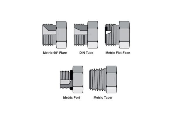
You compare the design of a globe valve vs ball valve by looking at the internal mechanism where globe valves use a linear plug and ball valves use a rotary sphere. The structural integrity of your system relies on these  hydraulic fittings  to manage flow velocity and pressure drops effectively. Choosing the right design prevents turbulence and cavitation that could otherwise damage your downstream equipment.

Ball Valve Standard Specification

What Are the Core Structural Differences?

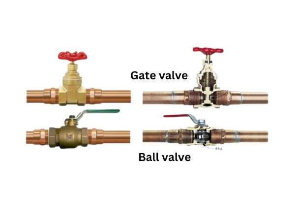
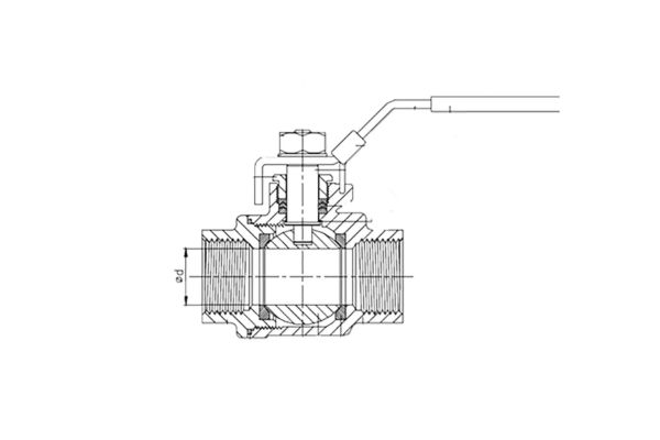
The globe valve features a spherical body separated by an internal baffle, which forces the fluid to change direction as it passes. This design allows you to have absolute control over the flow path, though it does result in a higher pressure drop. Conversely, the ball valve uses a simple through-hole design that offers a straight path for the fluid when fully open.

How Does Motion Type Affect Performance?

Linear motion in a globe valve allows for incremental adjustments, which is why you use it for precision throttling. You can move the plug closer to the seat in tiny steps to find the exact flow rate required. Rotary motion is much faster, providing a 90-degree turn that is perfect for emergency shut-offs or simple isolation tasks.

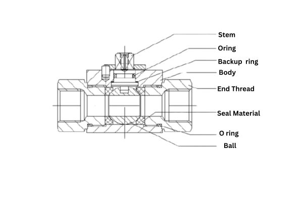
Which Interior Components Drive Fluid Flow?

The interaction between the plug and the seat in a globe valve is the primary driver of its flow regulation capabilities. You will notice that the shape of the plug can be customized to change the flow characteristic of the valve itself. Ball valves rely on the alignment of the bore with the pipe axis to dictate how much fluid can pass through at any given time.

This comparison helps you understand the physical constraints and mechanical advantages of each valve type in a standard piping environment.

Which Flow Control Is Best in Globe Valve vs Ball Valve?

For precision throttling and stable flow regulation, the globe valve is clearly the best choice in the globe valve vs ball valve debate. While ball valves excel at stopping flow quickly, they often struggle with the turbulence created when the ball is only partially open. You will find that globe valves provide a much more predictable response when you need to maintain a specific set point over long periods.

How Does Linear Travel Compare to Rotary Action?

Linear travel allows you to map the valve position directly to the flow rate with high accuracy and repeatability. This mechanical advantage is critical when you are managing sensitive thermal loops that require constant, minor adjustments. Rotary action is less precise for modulation because the flow area changes rapidly during the first and last few degrees of the turn.

What Is the Equal Percentage Flow Characteristic?

The equal percentage characteristic ensures that each increment of valve travel produces a consistent percentage change in the existing flow. You need this feature in HVAC systems to balance the non-linear heat transfer characteristics of water-to-air coils. Globe valves are naturally suited for this, though some advanced ball valves use specialized discs to mimic this behavior.

Which Design Offers Better Throttling Precision?

The globe valve offers superior throttling precision because the plug remains stable even when it is very close to the seat. You do not have to worry about the “hunting” behavior often seen in lower-quality rotary valves trying to maintain a low flow rate. This stability ensures that your pumps and chillers operate within their most efficient design parameters.

Does Rangeability Differ in Globe Valve vs Ball Valve?

Rangeability is significantly higher in a globe valve compared to a globe valve vs ball valve comparison, often exceeding 50:1 or 100:1. This means you can maintain accurate control at very low flow rates, which is essential during off-peak hours in a large facility. High rangeability  hydraulic adapters  and valves ensure that your system doesn’t lose control when demand drops.

Ball Valve design Topa

How Is the Flow Coefficient Calculated for Each?

The flow coefficient, or Cv, represents the volume of water that will flow through the valve with a pressure drop of one PSI. You calculate Cv by measuring the flow at different valve positions to create a performance curve. Globe valves typically have lower Cv values for their size because the internal path is more restrictive than a ball valve.

Which Valve Maintains Control at Low Flow Rates?

Globe valves maintain control at low flow rates because the plug design can be tapered to allow only a trickle of fluid. You will see this used frequently in steam applications where even a small amount of excess flow can cause temperature overshoots. Ball valves tend to become unstable at very low openings as the fluid velocity increases through the small crescent-shaped gap.

Which Close-off Is Tighter, Globe Valve vs Ball Valve?

In the contest of globe valve vs ball valve, the ball valve generally provides a tighter, bubble-tight close-off due to its floating ball design. The pressure of the fluid actually pushes the ball against the downstream seat, creating an increasingly tighter seal as pressure rises. This makes the ball valve the preferred option for isolation where you cannot afford any bypass leakage.

How Do Leakage Classifications Compare?

Leakage classifications range from Class I to Class VI, with Class VI representing the tightest “bubble-tight” seal available. Most ball valves easily achieve Class VI, while many globe valves are rated at Class IV or V. You must decide if your process can tolerate the minor weepage associated with metal-seated globe valves.

quarter turn ball valve

Which Design Better Prevents Fluid Bypass?

The rotary ball design prevents fluid bypass more effectively because the sealing surface is large and remains in constant contact with the seats. When you close a ball valve, the entire circumference of the bore is sealed off by the surrounding seat rings. Globe valves rely on a single point of contact between the plug and seat, which can be compromised by debris.

What Are the Costs of Using Globe Valve vs Ball Valve?

The initial purchase price of a globe valve vs ball valve is usually lower for the ball valve due to its simpler construction. However, you must consider the total cost of ownership, which includes the price of the actuator and the long-term energy costs associated with pressure drops. A cheaper valve that requires a massive actuator may end up costing you more than a high-quality integrated solution.

Which Option Requires a Lower Initial Investment?

Ball valves are mass-produced in a way that globe valves are not, which generally drives down their market price for standard sizes. You can often buy a high-quality stainless steel ball valve for a fraction of the cost of a comparable globe valve. This makes ball valves the primary choice for contractors working on tight budgets for terminal unit installations.

How Do Operational Expenses Impact Long-Term Value?

Operational expenses are driven by the energy used to pump fluid through the valve and the cost of maintenance over ten to twenty years. Because globe valves have a higher pressure drop, your pumps have to work harder, which increases your monthly electricity bill. You must weigh these energy costs against the precision benefits that a globe valve provides to your process.

Does Actuator Selection Change the Total Price?

Actuator selection can significantly shift the total price because globe valves require linear actuators that must generate high closing forces. You might find that the actuator for a 4-inch globe valve costs as much as the valve body itself. Ball valves use rotary actuators that are generally more compact and less expensive for the same pipe size and pressure rating.

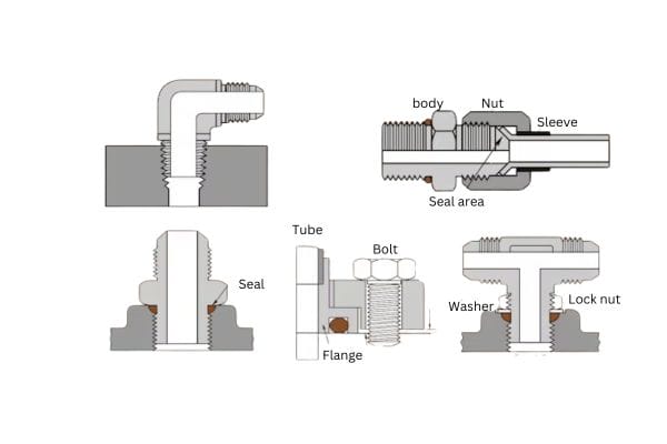
Is Installation Simpler for Globe Valve vs Ball Valve?

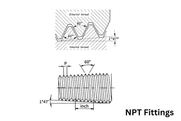
Installation is simpler for the ball valve in a globe valve vs ball valve comparison because it is lighter and more compact. You can fit ball valves into tight ceiling spaces or crowded mechanical rooms where a globe valve would be too bulky. Ensuring your fittings meet  SAE standards  ensures that the installation remains leak-free regardless of the valve type you choose.

Ball Valve Installation Direction

What Are the Physical Space and Weight Constraints?

Globe valves have a much larger “footprint” and can weigh twice as much as a ball valve of the same pipe size. You need to account for this extra weight when designing your pipe supports and hangers to prevent sagging or stress fractures. The height of the linear actuator on a globe valve also requires significant overhead clearance for maintenance access.

Does Piping Orientation Affect Valve Performance?

Piping orientation is more critical for globe valves because they must be installed with the flow in a specific direction (usually under the seat). If you install a globe valve backward, the fluid pressure can pull the plug into the seat, causing severe vibration and noise. Ball valves are typically bi-directional, giving you more flexibility during the piping layout phase of your project.

Which Actuator Mounting Process Is More Efficient?

The actuator mounting process for ball valves is highly standardized thanks to ISO 5211 mounting pads. You can swap actuators from different manufacturers with ease, knowing the bolt patterns and shaft dimensions will match. Globe valve actuators often require custom linkages and precise stem-height adjustments that make the mounting process more time-consuming for your technicians.

Conclusion

Whether you are designing a new steam plant or upgrading a domestic water loop, we can provide the high-quality components and technical guidance you need. Our team is ready to help you navigate these specifications to find the most cost-effective and durable solution for your business. For any questions regarding sizing, material compatibility, or customized fittings, please  contact us  today. We are committed to being your long-term partner in achieving industrial excellence and system reliability through superior hydraulic technology.

FAQ

Can I use a ball valve for steam throttling?

No, you should avoid this because standard ball valves have soft seats that will melt or erode quickly in steam service. The high-velocity steam will cause “wire-drawing” on the ball and seats, leading to permanent leaks and loss of control within a very short time.

What’s the best valve for an emergency fuel shut-off?

A ball valve is the best choice for this application because it provides a “bubble-tight” seal and can be closed in a quarter-turn. In a fire or leak scenario, you need the rapid, reliable isolation that only a rotary ball design can provide.

How do I know if my globe valve is installed backward?

You can tell by checking for excessive noise, vibration, or a “hammering” sound when the valve is close to the seat. Most globe valves have an arrow cast into the body showing the required flow direction; if the fluid enters above the seat instead of below it, the valve will behave poorly.

Can I replace a globe valve with a ball valve to save energy?

Yes, you can, provided that the application is for water and you select a “characterized” ball valve with a throttling disc. This will give you the low pressure drop of a ball valve while maintaining the control performance required for your HVAC coils.

Is it possible to repair a leaking ball valve seat?

No, in most cases, it is more cost-effective to replace the entire valve rather than attempt to repair a ball valve seat. Because the seats are typically pressed into the body at the factory, the labor involved in disassembly and reassembly usually exceeds the price of a new unit.

Gate Valve vs Ball Valve banner

Gate Valve vs Ball Valve: Key Differences and Best Explained

Gate valves and ball valves are among the most commonly used options, each offering unique benefits and ideal use cases. Selecting the appropriate type isn’t just about preference—it’s crucial for maintaining flow control, system durability, and operational efficiency.

What Are Gate Valves?

Definition

A gate valve is a type of valve used in fluid control systems to start or stop the flow of liquid or gas. It achieves this by lifting a “gate” out of the path of the fluid. Gate valves are particularly effective for applications requiring a full, unobstructed flow, and they’re commonly found in systems where high-pressure resistance is essential, such as water treatment plants, oil pipelines, and various industrial environments.

How Gate Valves Work

Gate valves operate using a linear motion to open or close the valve. When the valve’s handwheel or actuator is turned, the gate inside the valve is either lifted or lowered, moving perpendicular to the flow direction. This vertical movement allows the valve to fully open or close, which provides minimal resistance when fully open, reducing pressure drop across the valve. Gate valves aren’t ideal for throttling or flow modulation due to their slower operation time, as they require multiple turns to move between open and closed positions. Additionally, partially open gate valves can suffer from excessive wear and vibration.

Gate Valve

Types of Gate Valves

Rising Stem Gate Valve: In this type, the stem rises as the valve opens, providing a visible indicator of whether the valve is open or closed. However, it requires more installation space and is typically not ideal for confined areas.

Non-Rising Stem Gate Valve: The stem does not move upward as the valve opens, making it a good option for applications with limited vertical space. The stem remains inside the valve, with only the gate itself moving.

Wedge Gate Valve: Known for its ability to provide a tight seal, the wedge gate valve has a gate shaped like a wedge that presses firmly into the seat to prevent leaks. It is commonly used in high-pressure applications.

Parallel Slide Gate Valve: This type of gate valve has a parallel gate design instead of a wedge. It’s typically easier to open and close, with less risk of jamming under high pressures.

Key Features of Gate Valves

Flow Control: Gate valves are best suited for applications requiring either a fully open or fully closed position. When fully open, they allow unobstructed flow with minimal pressure drop, making them highly efficient for applications demanding maximum throughput.

Resistance to Pressure: Due to their robust construction, gate valves are highly resistant to pressure. This makes them a preferred choice for high-pressure environments, such as pipelines and industrial processing.

Slow Operation Time: Unlike quick-action valves, gate valves have a slower operation time due to the multiple turns required to fully open or close the gate. This characteristic makes them unsuitable for applications requiring frequent or rapid changes in flow.

What Are Ball Valves?

Definition

A ball valve is a type of valve used to control the flow of fluids through a rotary motion. It features a spherical ball with a hole through the center, which, when aligned with the pipeline, allows fluid to flow through. Ball valves are known for their reliability and ability to provide a tight seal, even after extended periods of disuse, making them ideal for rapid on/off control in a range of applications, from residential plumbing to complex industrial systems.

How Ball Valves Work

Ball valves operate using a quarter-turn mechanism. When the handle of the valve is turned 90 degrees, the ball inside rotates to either open or block the flow path. In the open position, the hole in the ball aligns with the flow direction, allowing fluids to pass freely. In the closed position, the solid part of the ball blocks the flow. This simple mechanism provides a fast and efficient way to control fluid flow, requiring only a short turn to fully open or close, unlike the multi-turn process required for gate valves. Ball valves are especially useful for applications where quick, frequent adjustments are needed.

Types of Ball Valves

Full Port Ball Valve: In a full port ball valve, the bore (or hole) in the ball matches the diameter of the pipeline, allowing for an unrestricted flow. This reduces pressure drop across the valve and is beneficial in applications where high flow rates are critical.

Standard Port Ball Valve: This type has a slightly smaller bore than the pipeline diameter, creating a small pressure drop. While it is less costly than a full port valve, it is suitable for applications where a minor reduction in flow is acceptable.

Trunnion Mounted Ball Valve: In this design, the ball is anchored at both the top and bottom, allowing it to handle higher pressures with reduced operating torque. Trunnion mounted valves are commonly used in larger pipelines and high-pressure applications.

Floating Ball Valve: The ball in this type is held in place by the valve seats but is otherwise free to “float” in the valve body. When the valve is closed, the pressure from the fluid pushes the ball against the downstream seat, creating a tight seal. Floating ball valves are generally used for smaller pipe diameters.

Ball Valve component

Key Features of Ball Valves

Quick Operation: Due to their quarter-turn mechanism, ball valves are extremely quick to operate. This makes them ideal for applications where rapid opening and closing are necessary.

Suitable for On/Off Control: Ball valves provide reliable on/off control without significant wear. They are highly effective in applications requiring immediate shutoff or full flow without throttling.

Pressure Handling: Ball valves are capable of handling high-pressure environments, particularly trunnion-mounted designs that support the ball securely, reducing stress on the valve seats.

Gate Valve vs Ball Valve: Key Differences

Understanding the distinctions between gate valves and ball valves is essential for selecting the appropriate valve for a given application. Here’s a comparison of their main differences:

Mechanism

Gate Valve: Utilizes a linear motion mechanism where a gate or wedge moves up and down perpendicular to the flow direction. This motion requires multiple turns to open or close the valve completely, making it a multi-turn valve.

Ball Valve: Operates with a rotary motion using a quarter-turn mechanism. A simple 90-degree turn of the handle or actuator rotates the ball inside, opening or closing the flow path quickly. This makes it highly effective for rapid on/off control.

Operation Speed

Gate Valve: Due to its multi-turn operation, a gate valve has a slower response time, making it suitable for gradual control in applications where quick shutoff is not a priority.

Ball Valve: With its quarter-turn mechanism, a ball valve offers instantaneous operation. This quick response is ideal for applications that need immediate shutoff or rapid on/off cycling.

Flow Control and Tightness

Gate Valve: Offers precise control over flow when used in fully open or fully closed positions. However, when partially open, it is less effective at sealing and may experience turbulence and wear, which can lead to leakage over time.

Ball Valve: Known for its leak-tight seal, even in high-pressure systems, ball valves are excellent for on/off control but not as ideal for precise throttling. Their simple design and tight shutoff make them highly effective in maintaining leak resistance.

Durability and Maintenance

Gate Valve: Gate valves are generally durable in high-pressure applications but are prone to wear and tear if frequently operated. The multi-turn mechanism can lead to mechanical wear, and maintenance may require more effort due to the complex internal structure.

Ball Valve: Ball valves have a longer lifespan and are easier to maintain due to their simpler design. The ball’s smooth surface minimizes wear, especially in low-friction applications. However, in abrasive environments, the valve seats may need replacement over time.

Installation and Cost Factors

Gate Valve: Typically, gate valves are more costly to install and maintain, especially in large pipelines, due to their larger size and multi-turn mechanism. They also require more space for operation, particularly rising stem types.

Ball Valve: Generally less costly to install and maintain compared to gate valves, ball valves are compact and require minimal space. They have lower installation and replacement costs, making them a cost-effective choice for most applications.

Pressure and Temperature Tolerance

Gate Valve: Suitable for high-pressure and high-temperature environments, gate valves are commonly used in demanding industrial applications where these factors are critical.

Ball Valve: Ball valves also perform well in high-pressure environments and can handle a broad range of temperatures, depending on the materials used. However, in extremely high-temperature applications, they may require specialized materials to maintain performance.

How to Choose: Gate Valve or Ball Valve?

Selecting between a gate valve and a ball valve depends on the unique demands of your system and the specific conditions in which the valve will operate. Here are some essential decision factors and common scenarios to help you make the best choice.

Decision Factors

1. System Requirements

Pressure: Consider the operating pressure of your system. Gate valves are typically better suited for applications with very high pressures, as their multi-turn mechanism and robust construction offer excellent resistance under extreme conditions. Ball valves can also handle high pressure, but specific designs, like trunnion-mounted ball valves, are better for very high-pressure systems.

Temperature: High-temperature environments may demand materials that can withstand extreme heat. Gate valves are often used in such scenarios. Ball valves, depending on their seat material, are also versatile but may require special construction for very high temperatures.

Flow Conditions: If precise control over flow rate is required, a gate valve may be preferable, as it can handle gradual flow changes better than a ball valve. For simple on/off control, however, the ball valve is typically the better choice due to its quick operation and ease of use.

2. Frequency of Use

Durability in Frequent Operations: If the valve will be operated frequently, ball valves are generally more durable and require less maintenance for high-cycle use, thanks to their simple quarter-turn operation. Gate valves, while durable, are better suited for applications with less frequent operation as their multi-turn mechanism can wear out with excessive use.

Long-Term Reliability: For applications where valves remain open or closed for extended periods, both valve types can be reliable. However, ball valves tend to maintain a tighter seal over time, making them more suited for applications where minimal leakage is essential.

3. Environment

Clean Environments: In clean environments, such as food processing or pharmaceutical applications, ball valves are often preferred due to their ease of cleaning and fewer internal parts that could trap contaminants.

Harsh Industrial Settings: In environments with abrasive particles, sludge, or other contaminants, gate valves might be a better choice. They are less likely to trap debris within the valve body and are typically constructed from materials that handle tough conditions.

Gate Valve vs Ball Valve

Common Scenarios: When to Choose a Gate Valve vs Ball Valve

High-Pressure Pipelines: For large, high-pressure pipelines that are opened and closed infrequently, a gate valve is often the preferred choice due to its robust design and ability to handle pressure fluctuations without excessive wear.

On/Off Flow Control: In applications where rapid shutoff is crucial—such as in water treatment, HVAC systems, or emergency shut-off lines—a ball valve is typically ideal. Its quarter-turn mechanism allows for instant on/off control, reducing response time.

Gradual Flow Control Applications: When precise flow adjustments are necessary, such as in certain chemical processing applications, a gate valve offers more control. Its slower, multi-turn mechanism allows for more gradual adjustments, which can be important in systems where pressure surges need to be minimized.

Corrosive or Clean Fluids: For clean or moderately corrosive fluids, ball valves are often preferred due to their ease of maintenance and reliable sealing properties. Their compact design is also beneficial in settings where space is limited.

Conclusion

Have you used gate or ball valves in your operations? If you have any questions or need more guidance on selecting the right valve for your application, please feel free to ask – we’re here to help!


FAQ

What is the main difference between a gate valve and a ball valve?

Gate valves use a multi-turn, linear motion to open/close gradually, while ball valves use a quarter-turn rotary motion for quick on/off control.

Which valve is better for high-pressure applications?

Both valves can handle high pressure, but gate valves are generally preferred for very high-pressure and high-temperature environments due to their robust design.

Can gate valves be used for frequent on/off operations?

Gate valves are less suitable for frequent operation as their multi-turn mechanism wears faster with repeated use. Ball valves are a better choice for frequent on/off control.

Are ball valves suitable for flow modulation?

Ball valves are best for on/off applications and do not offer the precision needed for gradual flow control. Gate valves are more suitable for modulating flow.

Which valve type requires less maintenance?

Ball valves usually require less maintenance due to their simpler design and durable sealing capabilities, especially in systems with high usage.

How can I choose between a gate valve and a ball valve?

Consider factors like pressure, temperature, flow control needs, and operational frequency. Gate valves are better for gradual control, while ball valves are ideal for quick, frequent operation.

Choosing Between Plug Valves vs Ball Valves for Your System banner

Choosing Between Plug Valves vs Ball Valves for Your System

Choosing between these components depends on whether your system requires a high-surface-area seal for low-pressure gases or a low-torque, versatile solution for high-pressure liquids. Imagine you are designing a high-stakes industrial line where even a minor leak could lead to catastrophic downtime or safety risks. You face the constant frustration of selecting hardware that either wears out too quickly or fails to provide a bubble-tight shutoff when you need it most. By evaluating the specific operational strengths of plug valves vs ball valves, you can secure a reliable, long-term solution for your fluid control challenges.

What Are the Core Design Basics of Plug Valves vs Ball Valves?

The fundamental design of plug valves vs ball valves differs primarily in the shape of the internal closing element, with one using a tapered cylinder and the other a spherical ball. While both utilize a quarter-turn mechanism to manage flow, their internal geometry dictates how they interact with the media. Understanding these structural variations is the first step in optimizing your hydraulic or fluid control setup.

plug valve

Defining the Conical Plug

A plug valve utilizes a tapered or cylindrical plug that fits tightly within the valve body to create a seal. The plug features one or more hollow passages that allow fluid to travel through when aligned with the pipe.

If you need a valve for low-pressure gas lines, the plug design is often preferred for its tight shutoff. The rectangular port shape provides a different flow characteristic than the circular bore found in other models.

Understanding the Rotating Sphere

A ball valve employs a spherical disc with a hole bored through its center to control flow. When the ball is turned 90 degrees, the hole either aligns with the flow path or is blocked by the valve body.

This design is highly scalable and can be found in sizes ranging from tiny instrumentation fittings to massive pipeline controllers. Because the ball only contacts the seats, it requires much less force to turn than a solid plug.

Selecting the right core design ensures that your internal components match the physical space and flow requirements of your machinery.

How Do Sealing Mechanisms Differ for Plug Valves vs Ball Valves?

Sealing performance in plug valves vs ball valves is determined by the amount of surface area contact between the closing element and the valve body. In a plug valve, the entire surface of the plug can act as a seal, whereas ball valves rely on dedicated ring-shaped seats. This distinction impacts how each valve handles different types of media density.

Surface Area Contact Comparison

Plug valves provide a much larger sealing surface, making them exceptionally good at preventing leaks in applications involving thin gases. This large contact area ensures that even if the valve body experiences slight thermal expansion, the seal remains intact.

However, the increased contact in a plug valve means more friction. You must decide if the trade-off for a superior seal is worth the extra effort required to turn the handle.

Understanding how these parts seal under pressure allows you to prevent environmental leaks and maintain system integrity.

Why Is Torque a Critical Factor for Plug Valves vs Ball Valves?

Operating torque in plug valves vs ball valves is a major consideration because it dictates the size and cost of the actuators you will need to purchase. Because plug valves have more surface area contact, they naturally require significantly more force to open and close than ball valves. This can lead to increased costs if you are automating your system with pneumatic or electric motors.

structure of ball valve

Operating Force and Actuator Compatibility

Ball valves are favored in automated systems because their low-torque requirement allows for smaller, more affordable actuators. The spherical shape minimizes friction against the seats, allowing for smooth, rapid cycles.

Now, consider that if you choose a plug valve for a large pipe, you might need a much larger motor than you originally anticipated. This could blow your budget and require more space in your facility.

Managing torque requirements effectively reduces the total cost of ownership for your automated fluid systems.

Can Plug Valves vs Ball Valves Handle Slurries More Effectively?

When dealing with slurries, mud, or sewage, plug valves vs ball valves perform differently based on how their internal cavities collect debris. Plug valves are generally considered superior for heavy slurries because they do not have the internal gaps where solids can settle and harden. A ball valve has a small space between the ball and the body that can trap particles, leading to internal damage over time.

Managing Solids and Debris

The “sweeping” motion of a plug valve helps clear the sealing surface of any built-up solids every time it is operated. This self-cleaning action makes it a favorite in the wastewater and mining industries.

If your media contains abrasive sand or thick sludge, the plug valve is your best bet for avoiding a seized valve. The solid plug simply pushes the debris out of the way rather than letting it get stuck in a cavity.

Choosing a valve that can handle particulate matter prevents frequent clogs and unexpected system shutdowns.

What Are the Maintenance Requirements for Plug Valves vs Ball Valves?

The maintenance protocols for plug valves vs ball valves vary significantly, with one requiring regular lubrication and the other often being a “replace-on-failure” component. Plug valves are designed for longevity through servicing, whereas standard ball valves are frequently discarded once the internal seats wear out. Knowing which maintenance path fits your team’s capabilities is essential for operational planning.

Lubrication and Part Replacement

Lubricated plug valves feature a chamber that allows you to inject sealant or grease to maintain the seal and reduce friction. This makes them highly durable in harsh environments but requires a disciplined maintenance schedule.

Most standard ball valves are not designed to be repaired. If the internal ball gets scratched, you usually have to replace the entire unit unless you have invested in a high-end 3-piece model.

Establishing a clear maintenance routine ensures that your valves remain functional for their intended lifespan without sudden failures.

Why Is Service Life Different Between Plug Valves vs Ball Valves?

The expected lifespan of plug valves vs ball valves depends on the wear patterns created by the movement of the internal parts. Because plug valves have a larger contact area, they can experience more friction-related wear, but they are also more robust against corrosion. Ball valves offer a long service life in clean fluids but can fail quickly if the small seating area is compromised by heat or chemicals.

Full Port Ball Valve Topa

Wear Patterns and Component Longevity

In a ball valve, the seats bear the brunt of the pressure and friction, which can lead to “compression set” or tearing over time. Once the seat is damaged, the valve will leak, regardless of how good the ball looks.

If you are running a high-cycle application where the valve opens and closes every few minutes, the ball valve is the champion of longevity. Its low-friction movement preserves the internal components through thousands of operations.

Selecting a valve with wear characteristics that match your cycle frequency maximizes the time between overhauls.

Can Plug Valves vs Ball Valves Support High-Pressure Systems?

Pressure ratings for plug valves vs ball valves generally favor ball valves for extreme high-pressure hydraulic applications. While plug valves are excellent for low-to-mid pressure, the high torque required to turn them becomes unmanageable as system pressure increases. Ball valves, especially trunnion-mounted designs, are engineered specifically to handle thousands of pounds of pressure without seizing.

Pressure Ratings and Tolerance

Modern hydraulic systems often exceed 3,000 PSI, a range where the balanced design of a ball valve excels. The ball can be supported by trunnions to prevent it from being pushed into the seats too forcefully.

If your system is operating at the limits of standard hardware, you need the mechanical advantage that a ball valve provides. It ensures that your operators can still manually shut off the flow in an emergency.

Ensuring your valves are rated for your system’s maximum pressure is the most critical safety step you can take.

What Are the Best Use Cases for Plug Valves vs Ball Valves?

Identifying the ideal environment for plug valves vs ball valves allows you to standardize your inventory and simplify training for your maintenance staff. Plug valves are the kings of the oil field and wastewater plants where “dirty” fluids are the norm. Ball valves are the standard for chemical processing, food and beverage, and general industrial hydraulics due to their cleanliness and speed.

Industrial Applications and Environment

In a sanitary environment like a brewery or pharmaceutical lab, ball valves are preferred because they can be polished to a high finish and easily cleaned. Plug valves are rarely used here because the large surface area and lubricants can contaminate the product.

If you are unsure, look at what the industry standard is for your specific niche. Most hydraulic systems will almost always utilize ball valves or specialized hydraulic fittings for their superior pressure handling.

Standardizing your valve selection based on industry-proven use cases reduces errors during installation and repair.

How Should You Finalize Selecting Plug Valves vs Ball Valves?

To make the final decision between plug valves vs ball valves, you must weigh your need for seal integrity against your requirements for automation and torque. Start by defining your media—is it a clean gas, a thick slurry, or a high-pressure hydraulic fluid? Once you have the media defined, look at your budget for actuation and your team’s ability to perform regular maintenance.

Evaluating Your Specific System Needs

Every system is unique, and sometimes the best choice is a hybrid approach using different valves for different stages of the process. You should never choose a valve based on price alone; the cost of a single failure far outweighs the initial savings.

The goal is a system that you don’t have to think about. A well-chosen valve operates silently and reliably in the background, allowing you to focus on your primary production goals.

Taking the time to perform a final review of your specifications prevents costly retrofitting after the system is built.

Conclusion

Selecting the right hardware for your system doesn’t have to be a guessing game that ends in leaks or mechanical failure. We understand that the pressure to maintain uptime while managing costs is a heavy burden for any engineer or facility manager. Our team provides high-quality hydraulic components that bridge the gap between performance and durability, ensuring your lines stay open and your seals stay tight. If you need expert guidance on which components will best serve your specific environment,  contact us today  to discuss your requirements and find the perfect fit for your operation.

FAQ

Can I use plug valves for throttling?

No, you generally should not use them for this purpose because they are designed for on/off service. Partial opening can cause the high-velocity media to erode the plug or the body, leading to a permanent leak.

What’s the best choice for high-pressure hydraulic systems?

Ball valves are the superior choice here due to their ability to handle extreme PSI with relatively low torque. They are much easier to actuate under pressure and are the standard in the hydraulic industry.

How do I know if my system needs a lubricated plug valve?

You should choose this option if you are working with large-diameter pipes or high-temperature media where friction would make a non-lubricated valve impossible to turn. The lubrication also provides an extra layer of protection against corrosive chemicals.

Can I automate a plug valve?

Yes, it is possible, but it is often more expensive than automating a ball valve. Because the torque requirements are so much higher, you will need a significantly larger and more powerful actuator to get the job done.

How do I know if a ball valve is leaking internally?

You will notice a pressure drop downstream even when the valve is in the fully closed position. This is usually a sign that the seats have been compromised by debris or have reached the end of their service life.

Hydraulic Fitting Sealing Methods banner

Hydraulic Fitting Sealing Methods: Understanding All Types

Sealing is a vital aspect of hydraulic systems as it prevents leaks, maintains the system’s pressure integrity, and ensures the safe and efficient operation of the entire setup. Without proper sealing, hydraulic systems can experience performance degradation, loss of power, or even complete failure.

What is Hydraulic Fitting Sealing?

Hydraulic systems are widely used across a variety of industries for their ability to transmit power and perform work efficiently. These systems rely on the precise flow of pressurized fluid to move machinery and perform tasks such as lifting, pressing, and driving mechanical processes.

Sealing in hydraulic fittings refers to the process of ensuring that fluid within the system remains contained at the connection points of pipes, hoses, valves, and other components. In a hydraulic system, fittings are used to connect various parts of the fluid circuit, and each of these connections must be properly sealed to prevent fluid leakage. A hydraulic fitting seal provides a barrier that stops fluid from escaping, which could compromise system performance, cause power loss, or even lead to hazardous conditions.

In essence, hydraulic fitting seals are designed to keep the hydraulic fluid at its optimal pressure, preventing leaks that could undermine the efficiency and safety of the system. In a hydraulic system, where fluids are generally under high pressure, these seals must not only prevent leakage but also withstand the extreme conditions of the system, including high pressures, variable temperatures, and potential chemical exposure.

Types of Seal Materials in Hydraulic Fittings

The selection of appropriate sealing material is paramount in maintaining the integrity of the hydraulic system. The right material must be chosen based on various factors, such as system pressure, temperature, fluid type, and the specific demands of the application. The most commonly used seal materials for hydraulic fittings are:

1. Rubber Seals

Rubber seals are one of the most common types of seals used in hydraulic fittings, thanks to their excellent flexibility, cost-effectiveness, and compatibility with various hydraulic fluids. The most commonly used rubber materials for hydraulic seals include Nitrile (Buna-N), EPDM (Ethylene Propylene Diene Monomer), and Neoprene. These materials provide excellent sealing in low to medium-pressure applications and are effective at sealing against a wide range of fluids such as water, oil, and grease.

2. Metal Seals

Metal seals are used in environments where rubber or elastomeric seals may not be able to perform effectively due to high pressure or extreme temperatures. Metal-to-metal sealing is commonly used in high-pressure applications such as power plants, offshore rigs, and aerospace applications. Metal seals are constructed from materials such as stainless steel, brass, or titanium, which provide excellent durability and resistance to wear.

3. Elastomeric Seals

Elastomeric seals are typically made from synthetic rubbers like Viton, Silicone, and Fluorosilicone. These materials are known for their ability to handle higher temperatures, aggressive chemicals, and harsh hydraulic fluids.

Sealing methods

Purpose of Hydraulic Fitting Seals

The primary purposes of hydraulic fitting seals are as follows:

Prevent Leaks: Hydraulic systems operate under high pressure, and even a small leak can result in significant fluid loss, reduced system performance, and even catastrophic failure. Seals prevent the fluid from escaping at the connection points of pipes, hoses, valves, and other hydraulic components, thereby maintaining the integrity of the system. Leak prevention also reduces the environmental impact of hydraulic fluid loss.

Protect Against Contamination: Contaminants, such as dirt, water, air, and debris, can damage the hydraulic fluid and components, leading to reduced efficiency and failure of the system. Hydraulic fitting seals protect the fluid from contamination by preventing foreign particles from entering the system. This helps ensure that the hydraulic fluid remains clean and maintains its operational properties, thus enhancing the performance and longevity of the system.

Maintain Pressure Integrity: Hydraulic systems rely on the precise control of pressure to perform tasks effectively. Seals help maintain this pressure by preventing leaks that would otherwise cause fluctuations in system pressure. Maintaining stable pressure is essential for the efficient operation of the system, as even minor pressure drops can lead to inefficiency, poor performance, or system failure.

Types of Hydraulic Fitting Seals

O-Ring Seals

O-ring seals are one of the most common and versatile sealing solutions used in hydraulic fittings. An O-ring consists of a simple circular elastomeric ring designed to fit into a groove on the mating surface of two parts. When compressed between the surfaces, the O-ring creates a tight seal, preventing fluid leakage.

Advantages:

Cost-effective: O-rings are relatively inexpensive to produce and easy to install, making them a popular choice for many applications.

Versatility: They are suitable for a wide range of pressure levels and are compatible with most fluids, including oils, water, and gases.

Simple Design: The design of O-rings is straightforward, reducing the system’s complexity and the likelihood of installation errors.

Disadvantages:

Limited High-Temperature Tolerance: O-rings can degrade under extreme temperatures, especially in high-heat applications unless made from specialized materials.

Compression Set: Over time, O-rings can lose their elasticity and become prone to leaks, particularly if the system is exposed to high pressures or fluctuating temperatures.

Common Applications: O-ring seals are used extensively in hydraulic cylinders, valve assemblies, pumps, and hose connections. Their ability to seal both static and dynamic connections makes them invaluable in systems with regular movement or vibration.

Installation Tips:

Ensure the groove dimensions are correct to prevent the O-ring from being over-compressed or pinched.

Lubricate the O-ring before installation to avoid damage during fitting.

Inspect the O-ring for cracks or defects before use to prevent leaks.

Compression Seals

Compression seals work by forming a seal through the application of pressure between the mating surfaces of two parts. These seals are typically made from elastomeric materials like rubber or silicone, and they rely on compressive force to create a barrier against fluid leakage.

Benefits:

Effective under Pressure: Compression seals are effective in high-pressure applications, providing a strong barrier between components.

Simple Design: These seals are easy to install and replace, making maintenance straightforward.

Flexibility: Compression seals can accommodate slight variations in the surface or alignment of parts.

Limitations:

Limited Durability: Over time, compression seals can lose their elasticity, which may lead to leaks if not properly maintained or replaced.

Deformation: Continuous compression may lead to the deformation of the seal, affecting its ability to maintain a tight seal.

Typical Applications: Compression seals are commonly used in hydraulic systems with fixed joints, such as flanged fittings, pipe connections, and valves. Their ability to maintain a seal under static pressure makes them ideal for these applications.

Flanged Seals

Flanged seals consist of a metal or elastomeric sealing ring that fits into a flange groove, providing a tight seal when the two flanged components are bolted together. This type of seal is often used in high-pressure and high-temperature environments.

How They Work: The flanged seal works by using the flange’s pressure to compress the seal, creating a barrier against leakage. The seal’s material properties allow it to deform slightly to ensure a snug fit between the parts.

Pros:

High-Pressure Resistance: Flanged seals can withstand extremely high pressures without failure, making them ideal for heavy-duty hydraulic systems.

Durability: These seals are typically durable and have a long service life.

Reliable Seal: Flanged seals are highly reliable and are less prone to failure due to their robust construction.

Cons:

Installation Complexity: Installation can be more involved than simpler seals, requiring careful alignment and bolts or fasteners.

Cost: Flanged seals tend to be more expensive than basic seals, both in terms of material costs and installation.

Common Applications: Flanged seals are commonly found in large hydraulic systems, such as those used in heavy machinery, power plants, and offshore oil rigs. They are also used in heat exchangers and other high-pressure applications.

Hydraulic Fitting Sealing Methods

Threaded Seals

Threaded seals are used in fittings that involve threaded connections, where a sealant is applied to the threads to prevent fluid leaks. These seals can be created using various materials such as Teflon tape, anaerobic sealants, or metal-based compounds.

How They Work: The sealing material fills the gaps between the threads when the connection is tightened, forming a seal that prevents fluid from escaping. The compressive forces from tightening the threaded parts also help in forming a stronger seal.

When to Use: Threaded seals are typically used in applications where components are joined by threaded connections. They are especially useful when disassembly is needed for maintenance or repair.

Benefits:

Ease of Use: Threaded seals are relatively easy to apply, especially with pre-applied sealants.

Adaptability: They can be used in a variety of sizes and configurations.

Leak Prevention: They provide an excellent seal against both fluids and gases, preventing leakage from the threads.

Challenges:

Installation Care: Over-tightening or under-tightening threaded seals can cause leaks or damage to the components.

Material Compatibility: Some sealants may degrade with exposure to certain hydraulic fluids, limiting their use in specific environments.

Metal-to-Metal Seals

Metal-to-metal seals are used in high-pressure and high-temperature applications where elastomeric seals may not perform adequately. These seals consist of metal components that form a tight seal without the use of elastomeric materials. The metal sealing surfaces create a barrier by being compressed against one another.

How They Function: In metal-to-metal seals, the mating surfaces of the two parts are designed to be smooth and perfectly aligned. When pressure is applied, the metal surfaces deform slightly, creating a seal that is resistant to leakage.

Advantages:

Extreme Durability: Metal-to-metal seals are extremely durable and can withstand extreme conditions without failing, making them ideal for harsh environments.

High-Temperature and Pressure Resistance: They are particularly useful in systems that operate under very high pressures and temperatures, where traditional sealing materials might fail.

Longevity: These seals have a longer service life compared to elastomeric seals in certain applications, especially in aggressive environments.

Factors to Consider When Choosing Hydraulic Fitting Sealing Methods

Selecting the right sealing method for hydraulic fittings is crucial for the performance, efficiency, and safety of a hydraulic system. Several factors influence the decision-making process, including the system’s pressure and temperature, the type of hydraulic fluid used, and the environmental conditions in which the system operates.

Pressure and Temperature

Pressure and temperature are two of the most critical factors that affect the selection of sealing materials for hydraulic systems. The sealing material must be capable of withstanding the operating pressures and temperatures without failing, degrading, or losing its sealing ability.

Pressure: Seals must maintain their integrity even under varying levels of pressure. High-pressure systems, such as those used in heavy machinery, power generation, and oil rigs, require seals that can withstand significant stress without failure. Materials like metal seals and high-performance elastomers (e.g., Viton or HNBR) are suitable for such applications. For lower-pressure systems, seals made of rubber (e.g., Nitrile) are often sufficient.

Temperature: Extreme temperatures can cause materials to degrade, harden, or become too soft, leading to loss of sealing ability. For high-temperature applications (above 200°F / 93°C), Viton seals are preferred due to their high-temperature resistance. In contrast, systems that operate at lower temperatures may use materials like EPDM or Nitrile, which are more cost-effective and perform well within moderate temperature ranges. Choosing the correct material ensures that the seal remains effective and doesn’t break down under thermal stress.

For both temperature and pressure extremes, metal-to-metal seals or high-performance elastomers are ideal as they can handle the stresses of both high pressures and temperatures.

Fluid Compatibility

The type of hydraulic fluid used in the system plays a significant role in choosing the right seal material. Hydraulic fluids can vary widely in terms of their chemical properties, including oil-based, water-based, synthetic fluids, and more. Each of these fluids interacts differently with seal materials, which is why compatibility must be carefully considered.

Chemical Resistance: Certain hydraulic fluids, such as phosphate esters or synthetic oils, may react adversely with some seal materials, leading to degradation, swelling, or hardening of the seal. For example, Nitrile rubber is highly compatible with mineral oils but may degrade in contact with water-based fluids. On the other hand, Viton or fluoro silicone seals are more chemically resistant and are better suited for aggressive fluids or environments where fluid types may change.

Hydraulic Fluid Type: Oil-based hydraulic fluids often work well with Nitrile (Buna-N) seals, while water-based fluids such as water-glycol or phosphate ester fluids require materials with higher chemical resistance, such as EPDM or Viton. For systems using synthetic fluids or fuels, seals made from materials like Fluorosilicone or PTFE are often recommended.

Selecting the correct seal material based on the fluid type helps prevent chemical degradation, ensuring the system’s longevity and reliability.

Low Temperatures

Environmental Considerations

Environmental factors can have a significant impact on the performance and lifespan of hydraulic seals. Exposure to elements such as water, dust, ultraviolet (UV) rays, and chemicals in the atmosphere can degrade seals over time. Choosing seals that can withstand these environmental factors is essential for maintaining system integrity.

Water Exposure: In environments where seals are exposed to moisture or water, materials like EPDM and Nitrile offer resistance to water absorption and maintain their sealing properties even when exposed to wet conditions. Fluorosilicone seals are also highly resistant to water and can perform well in marine environments or where frequent washdowns are necessary.

Dust and Debris: Seals used in dusty or dirty environments, such as construction or mining, must be resistant to abrasion and capable of preventing particles from entering the system. Rubber seals (e.g., Nitrile) or elastomers like HNBR are suitable for these environments as they can form tight seals that prevent dirt and debris from contaminating the hydraulic fluid.

UV Exposure: For outdoor hydraulic systems exposed to sunlight, UV-resistant materials like EPDM and Silicone seals are recommended. UV rays can cause degradation in standard rubber materials, leading to hardening, cracking, and loss of sealing capability.

Common Issues with Hydraulic Fitting Seals and How to Prevent Them

Leaking Seals

One of the most prevalent issues with hydraulic seals is leakage, often caused by improper installation, misalignment, or wear. Over time, seals can degrade, leading to small gaps that allow fluid to escape.

Causes: Leaking seals may result from insufficient compression, incorrect sizing, damage during installation, or wear due to high-pressure cycles. Misalignment of components or improper assembly can also lead to leaks.

Prevention Tips:

Ensure that seals are the correct size and fit snugly within their grooves.

Use lubrication during installation to prevent tearing and to allow seals to settle correctly.

Regularly inspect seals for signs of wear or damage and replace them as needed.

Align components carefully to avoid creating uneven pressure on the seals, which can lead to leaks over time.

Wear and Tear on Seals

Common Causes of Seal Degradation: Seals in hydraulic systems are subjected to constant friction, pressure, and sometimes harsh chemicals. Over time, this exposure can lead to degradation, reducing the seal’s ability to function effectively. Common causes of wear and tear on seals include:

Abrasion: Friction between the seal and the mating surfaces can cause the material to wear down, leading to leaks. In high-velocity systems, abrasion can be accelerated.

Over-Compression: When seals are compressed beyond their design limits, they may lose their shape or become permanently deformed, leading to ineffective sealing and eventual failure.

Chemical Exposure: Harsh fluids or chemicals can degrade certain seal materials, leading to cracking or swelling, which compromises the seal.

Best Practices to Prevent Premature Wear

To minimize wear and tear on seals, the following measures should be taken:

Use Appropriate Materials: Select seal materials that are suited to the specific operating conditions of the system. For example, choose seals made of high-resilience materials for high-friction environments or elastomers with better chemical resistance when dealing with aggressive fluids.

Regular Inspection and Cleaning: Inspect seals regularly for signs of wear or damage, such as cracks, abrasions, or swelling. Cleaning the seals to remove dirt or debris can also help prevent abrasion.

Ensure Correct Fit: Properly hydraulic fitting seals are less likely to experience over-compression or uneven wear. Ensure that the seal dimensions match the fitting precisely to avoid excess pressure on the seal.

Seal Material Failure

Reasons for Seal Material Failure: Seal material failure can occur when the seal material no longer performs as intended, which can be due to several factors:

Temperature Extremes: Exposure to temperatures outside the recommended range for the seal material can cause it to harden, soften, or degrade, leading to failure. For example, rubber seals may become brittle at low temperatures, while elastomers may soften or swell at high temperatures.

Fluid Compatibility Issues: If the seal material is not compatible with the hydraulic fluid, it can degrade or swell, leading to failure. For instance, Nitrile seals are not suitable for systems using phosphate ester-based fluids, as they degrade rapidly.

UV and Environmental Damage: UV exposure, especially in outdoor applications, can cause certain seal materials to crack or become brittle over time. Similarly, exposure to dust, dirt, or water can impact seal performance.

How to Select the Right Materials to Prevent Failures

To minimize the risk of seal material failure, the following steps should be taken:

Temperature and Fluid Compatibility: Ensure that the selected seal material is designed to withstand the operating temperature and is compatible with the type of hydraulic fluid in use. For instance, Viton is suitable for high-temperature applications, while EPDM is ideal for water-based fluids.

Environmental Protection: If the seal is exposed to harsh environmental conditions, choose materials with UV resistance or the ability to withstand abrasion. Silicone and HNBR (Hydrogenated Nitrile Butadiene Rubber) are good choices for UV-resilient applications.

Conclusion

The right seal material not only prolongs the life of the system and its components but also improves overall system performance and minimizes downtime and costly repairs. Investing in high-quality seals tailored to your system’s needs is a crucial step in maintaining smooth operation and ensuring safety in demanding environments.


FAQ

What is the purpose of hydraulic fitting seals?

Hydraulic fitting seals are designed to prevent fluid leaks, protect against contamination, and maintain pressure integrity in hydraulic systems. They ensure the system operates efficiently and safely by keeping the fluid contained within the components.

What materials are commonly used for hydraulic seals?

Common seal materials include rubber (e.g., Nitrile, EPDM), elastomers (e.g., Viton, Fluorosilicone), and metal (e.g., stainless steel, brass). The choice of material depends on the system’s pressure, temperature, and fluid compatibility.

How do temperature and pressure affect seal performance?

Extreme temperatures and high pressures can cause seals to degrade or lose their sealing capabilities. It’s crucial to select materials that can withstand the system’s operating conditions. For high-temperature or high-pressure systems, materials like Viton or metal seals are often used.

What factors should I consider when selecting a hydraulic seal?

Key factors include the system’s pressure and temperature, the type of hydraulic fluid used, and environmental conditions (e.g., exposure to water, dust, UV rays). These factors determine the most suitable seal material for your system.

How often should hydraulic seals be replaced?

Hydraulic seals should be inspected regularly for wear and tear. The replacement frequency depends on system usage, fluid conditions, and environmental factors. If seals begin to leak or show signs of degradation, they should be replaced immediately to prevent system failure.

Can a single type of seal be used for all hydraulic systems?

No, each hydraulic system has specific requirements based on pressure, temperature, and fluid type. It’s important to choose the right seal type tailored to the particular conditions of your system for optimal performance and longevity.

Terms and Definitions of Hydraulic Fittings banner

Terms and Definitions of Hydraulic Fittings 

Precise terminology enables professionals in the field to communicate effectively and ensure that the right components are selected for specific tasks. A strong grasp of hydraulic fitting definitions not only prevents errors during system design but also helps streamline troubleshooting and repairs, making system maintenance more efficient.

Basic Definitions of Hydraulic Fittings

Hydraulic Fitting

A hydraulic fitting is a mechanical component designed to connect two or more elements of a hydraulic system, such as tubes, pipes, hoses, or other fittings. These connections facilitate the flow of hydraulic fluid while maintaining system integrity under high pressure and various environmental conditions. Hydraulic fittings are essential for ensuring the secure and efficient transfer of fluid between different components of the hydraulic circuit.

There are several types of hydraulic fittings, each designed for specific applications:

Each of these fitting types has specific characteristics suited to particular system requirements, whether it’s for flexibility, pressure control, or durability.

Thread Terminology

Thread terminology is essential when selecting and identifying hydraulic fittings, as the thread type and specifications directly affect the fitting’s compatibility with other components. Understanding the different thread-related terms helps ensure that fittings are correctly matched to their corresponding ports or adapters.

Thread Form

The thread form refers to the shape of the threads on the fitting, which is critical for ensuring the correct connection between the fitting and its corresponding port or hose. The form is determined by the angle between the sides of the thread (the flanks). For example, common thread forms include:

The correct thread form is crucial because mismatched thread forms can result in poor sealing, leakage, and eventual system failure. Identifying the right thread form requires careful inspection of the fitting’s geometry and ensuring it matches the port or coupling to which it will connect.

Thread Pitch

Thread pitch refers to the distance between two adjacent threads on a fitting, usually measured in millimeters (for metric threads) or threads per inch (for imperial threads). It is essential to match the thread pitch between fittings to ensure a proper seal and fit. For example, a 1.5mm pitch means that there is a 1.5mm gap between two consecutive threads, which affects the fitting’s tightness and sealing capabilities.

Measuring thread pitch can be done using tools like a pitch gauge or calipers, but the pitch must match between fittings and ports. If the pitch does not match, it can lead to cross-threading, improper sealing, or damage to the threads.

Threads per Inch (TPI)

In imperial systems, Threads per Inch (TPI) is a critical measurement that identifies the number of threads in one inch of length. For example, a 1/4″-20 fitting would have 20 threads in every inch. TPI is especially important for threaded fittings such as NPT, BSP, and JIC, where the number of threads determines how tightly the fitting will seal.

The TPI measurement is used in the context of imperial-sized fittings and helps in identifying the type of thread. It’s essential to ensure that the TPI of both the fitting and the port are the same for a secure, leak-free connection. A thread gauge is often used to measure TPI and ensure proper matching.

hydraulic hose measure Topa

Nominal Size vs Dash Size

Understanding the difference between Nominal Size and Dash Size is crucial for correctly identifying and selecting hydraulic fittings. These terms refer to the way the size of fittings is classified, which can sometimes be confusing.

Nominal Size

Nominal size is a general reference to the size of the fitting or pipe used for identification purposes, but it does not correspond to an exact measurement. For instance, a 1/2-inch nominal pipe may have an actual outside diameter (O.D.) of 0.840 inches. Nominal size is a standardized reference that helps categorize fittings and components, but it does not directly relate to the precise dimensions needed for proper fitting selection.

Nominal size is commonly used when discussing pipes, tubes, and fittings, and it is often confused with actual dimensions. However, it serves as a simplified reference to group fittings into common categories based on their general size.

Dash Size

On the other hand, dash size refers to the specific size measurement of a hydraulic fitting, typically in inches or millimeters. Dash sizes are used to indicate the fitting’s diameter and are part of the fitting’s part number. For example, a fitting with a part number of “08” typically refers to a 1/2-inch fitting, as the dash size corresponds to a specific measurement.

Dash sizes are essential in making sure the fitting is compatible with other components, especially when precise sizing is necessary for proper fluid flow and sealing. The dash size is often listed alongside the part number to make identification straightforward and ensure the correct fitting is chosen for a system.

Understanding Thread Types and Thread Characteristics

Common Thread Types

Thread types are crucial when selecting hydraulic fittings, as the thread form determines the compatibility and sealing ability of the connection. Various thread standards have been developed globally, each with its own design specifications, intended uses, and applications. Understanding the differences between these common thread types will help ensure the proper fitting is chosen for specific hydraulic systems.

BSP (British Standard Pipe)

BSP threads are a type of parallel (BSPP) or tapered (BSPT) thread commonly used in the United Kingdom and other regions following British standards. BSPP is often used for hydraulic systems that require non-leaking connections, where the sealing is achieved through the compression of an O-ring or seal. BSPT, on the other hand, has a tapered thread that seals by wedging the threads together, making it suitable for applications where higher pressure or more robust seals are needed.

Applications: Common in the UK, Europe, and other regions, BSP threads are found in industries like automotive, plumbing, and hydraulic systems, particularly where O-rings or compression fittings are used.

NPT (National Pipe Thread)

NPT is a widely used thread type in North America and is designed for creating tight, leak-proof connections in systems involving fluid or gas. It is a tapered thread (like BSPT) that seals by wedging the threads together. NPT threads are commonly used in applications that require high-pressure fluid transfer.

Applications: NPT threads are often found in North American hydraulic systems, as well as in plumbing, automotive, and industrial applications, where the fluid pressure is high and leakage prevention is essential.

JIC (Joint Industrial Council)

JIC threads are a type of flare fitting thread, primarily used in North American hydraulic systems. JIC threads have a 37-degree flare angle, and the sealing occurs between the flat face of the fitting and the flare of the hose or pipe. These threads are typically used for high-pressure applications because the flare creates a tight seal that resists vibration and high stresses.

Applications: JIC is commonly used in high-pressure applications such as hydraulic systems in construction equipment, aircraft, and other industrial machinery, where vibration resistance is critical.

Metric Threads

Metric threads are commonly used worldwide and are particularly prevalent in Europe and Asia. These threads follow the ISO metric system, with sizes indicated by the diameter and pitch in millimeters. Unlike imperial thread types (e.g., NPT, JIC), metric threads use a direct measurement system, making them easier to understand and apply across international markets.

Applications: Metric threads are standard in many European and Asian countries for hydraulic systems, automotive applications, and fluid transfer systems in industries ranging from manufacturing to robotics.

ORB (O-Ring Boss) and ORFS (O-Ring Face Seal)

ORB and ORFS are thread types used in hydraulic fittings designed to create a leak-proof seal using an O-ring. ORB is a straight thread with a machined groove for an O-ring, while ORFS uses a flat face and an O-ring to seal the connection. Both threads offer reliable sealing and are resistant to the leakage of high-pressure fluids, making them ideal for applications that require superior sealing performance.

Applications: ORB and ORFS are typically used in high-pressure hydraulic systems in industries such as aerospace, oil and gas, construction, and heavy equipment.

Comparison of Different Thread Types and Their Applications

Each thread type serves a specific purpose based on factors such as pressure, leak prevention, sealing method, and the mechanical stresses the system is subjected to. Here is a brief comparison of the thread types discussed:

Thread Form

The thread form refers to the geometric shape of the thread and its angle. This angle, known as the flank angle, is a key factor in determining whether two components will properly mate and seal. It directly affects the torque required to tighten the fitting and the overall performance of the connection.

Major vs Minor Diameter

When identifying threads, the major diameter and minor diameter are two critical measurements, especially when comparing male and female threads.

By using a caliper or micrometer, these diameters can be measured, and their values can be compared to known specifications to verify thread compatibility.

Thread Pitch and Pitch Measurement

Thread pitch refers to the distance between two adjacent thread crests, and it is essential for proper thread identification. It plays a significant role in determining how tightly the threads will fit together.

Pitch is usually measured in millimeters for metric threads or threads per inch (TPI) for imperial threads.

Pitch Measurement: To measure thread pitch, a pitch gauge is used. This tool allows you to match the gauge’s teeth with the threads to determine the correct pitch. For imperial threads, you would typically count the number of threads per inch (TPI), while for metric threads, you measure the distance between crests in millimeters.

Understanding Fitting Sizes and Classification

How Fittings Are Classified

Hydraulic fittings are classified based on several factors, such as thread type, material, size, and specific application. Fitting part numbers play a key role in this classification, providing essential information about the fitting’s dimensions, thread configuration, and type of connection. Understanding how to interpret these part numbers is critical for selecting the right fitting for any hydraulic system.

Part Numbering and Its Significance

A hydraulic fitting part number typically includes several elements that denote specific characteristics of the fitting. These include:

By understanding part numbers, hydraulic professionals can quickly identify the most important attributes of a fitting, such as size, thread type, and compatibility with hoses, tubes, or ports.

How to Read Hydraulic Fitting Part Numbers

To illustrate, let’s break down a typical hydraulic fitting part number:

Example: 0708-04-04

In this example, the part number quickly provides critical information, helping users determine the correct fitting for their application.

Fitting Sizing and Dash Numbers

Fitting sizes are often represented using dash numbers, which denote the diameter of the hose or tube that the fitting is designed to connect to. However, the dash number itself does not represent the exact dimension of the fitting; it is a convenient identifier that correlates to a particular size range.

How Sizing Is Determined by Dash Numbers

Dash numbers are typically used in hydraulic systems to indicate the internal or external diameter of a hose or tube that the fitting connects to. For example:

These dash numbers are standardized across many hydraulic systems, which allows for easier fitting identification and selection. However, it is essential to keep in mind that the actual measurements may slightly vary, especially between different manufacturers or systems.

The Relationship to Actual Dimensions

The dash number provides an approximation of the size but does not always match the exact diameter. For example:

Dash -04: Often refers to a 0.375″ nominal size, which corresponds to a 1/4″ tube or hose. However, the actual outer diameter (OD) might be slightly different depending on the specific fitting type.

To ensure proper selection, it is crucial to cross-reference dash sizes with actual measurements of the components involved, especially when working with systems requiring precise connections.

Conversion Between Nominal Size and Actual Size Measurements

In some cases, the nominal size of a fitting or hose does not directly match its physical dimensions. This difference can be seen in both nominal size and actual size measurements. Nominal size refers to a rounded figure used for easy reference, while actual size refers to the true dimension of the fitting.

For instance:

Engineers, technicians, and hydraulic professionals need to be familiar with both nominal and actual sizes to ensure proper fitting selection and avoid potential issues with misfitting components.

Metric Thread types

Metric vs. Imperial Sizing

Fitting sizes can be classified in either metric or imperial systems, and understanding the differences is crucial when selecting components for international applications or when working with systems from different regions.

Key Differences in Measurement Systems

The Impact of These Differences on Fitting Selection and Compatibility

Hydraulic fittings made for imperial-sized systems cannot be directly used with metric-sized systems, and vice versa. The primary issue lies in the sizing and thread dimensions, which may not align correctly.

For example, a dash -06 (3/8″) imperial fitting is not directly interchangeable with a 6mm metric fitting, as their dimensions are not the same. This mismatch can lead to issues with sealing, leakage, and overall system performance.

Understanding Pressure Ratings and Flow Capacity

Pressure Rating

The pressure rating of a hydraulic fitting refers to the maximum pressure that the fitting is designed to withstand under normal operating conditions. It is a critical parameter when selecting fittings for hydraulic systems, as using a fitting with an insufficient pressure rating can lead to catastrophic failures, including leaks, rupture, or damage to other components.

What Pressure Rating Means for Hydraulic Fittings

Pressure ratings are usually expressed in terms of pounds per square inch (PSI), bar, or MPa (megapascals). These ratings indicate the maximum internal pressure that the fitting can safely handle. There are a few key factors to consider:

How to Read Pressure Ratings

Hydraulic fitting manufacturers often provide pressure ratings as part of the technical specifications. It is crucial to ensure that the fitting’s pressure rating matches or exceeds the maximum operating pressure of the system. When reviewing the ratings:

When selecting hydraulic fittings, always match the fitting’s pressure rating with the system’s maximum operating pressure. It’s essential to factor in safety margins and avoid using fittings that are rated below the maximum operating pressure of the system.

Flow Capacity

The flow capacity of a hydraulic fitting refers to the volume of fluid that can pass through the fitting within a given period without causing pressure loss or flow restrictions. A fitting’s flow capacity directly influences the overall efficiency of the hydraulic system and its ability to operate smoothly under various conditions.

How Fittings Influence Flow Capacity and System Efficiency

Flow capacity is determined by several factors, including the size and design of the fitting. When fluid flows through a fitting, the following elements affect its ability to maintain efficient flow:

Relationship Between Fitting Size, Design, and Fluid Flow

The relationship between fitting size, design, and fluid flow is directly correlated. A well-designed fitting with a larger bore size will facilitate better flow, while a fitting with a poor design or a small bore will cause flow restrictions, resulting in increased system pressure, reduced efficiency, and potential overheating.

Conclusion

As hydraulic systems evolve, so too does the terminology and the precision required to manage them effectively. We encourage all professionals to regularly review fitting specifications, ensure correct installation, and use proper diagnostic tools. If you need any hydraulic fittings, please contact us!


FAQ

What is a hydraulic fitting?

A hydraulic fitting is a connector used in fluid systems to join pipes, hoses, or tubes, ensuring leak-free and efficient fluid transfer. They come in various types, such as elbows, tees, and adapters.

What is the difference between BSP and NPT threads?

BSP (British Standard Pipe) uses parallel threads for sealing, while NPT (National Pipe Thread) uses tapered threads that create a tighter seal when tightened. BSP is more common in Europe, while NPT is often used in North America.

How do I determine the correct size for a hydraulic fitting?

Fitting sizes are typically determined by the dash size (e.g., 04, 06) or the nominal size. The dash size corresponds to the internal or external diameter of the fitting, while the nominal size is a reference size and may differ slightly in actual measurements.

What is the importance of thread pitch in hydraulic fittings?

Thread pitch refers to the distance between thread crests and is essential for ensuring compatibility between fittings. Incorrect thread pitch can lead to leaks or mechanical failure.

Why is pressure rating important for hydraulic fittings?

The pressure rating indicates the maximum pressure the fitting can safely handle. Choosing a fitting with the appropriate pressure rating prevents failure under high-pressure conditions, ensuring system safety.

Can I use metric and imperial fittings together?

It is not recommended to mix metric and imperial fittings due to differences in thread types and sizes. Compatibility issues can lead to poor seals, leaks, and system failure. Always ensure fittings match the system specifications.

How to Identify NPT Threads in Hydraulic Couplers banner

How to Identify NPT Threads in Hydraulic Couplings

An incorrect thread connection can lead to leaks, pressure loss, and system failures—problems that can cause significant downtime, costly repairs, and even safety hazards. The risk of leaks, in particular, is one of the primary concerns in hydraulic systems, as improperly matched threads can result in hazardous fluid spills or catastrophic system malfunctions.

Understanding Hydraulic Thread Types

Hydraulic systems rely on the proper connection of components to function efficiently, and a critical aspect of these connections is the type of thread used in quick couplings, valves, hoses, and other fittings. Threads are essential for sealing the interfaces between components, and they come in various designs.

Overview of Thread Types

NPT (National Pipe Tapered Thread):

NPT threads are one of the most common thread types used in hydraulic systems. They are tapered threads, which means they have a conical shape that helps form a tight seal when the two parts are screwed together. As the fitting is tightened, the threads compress, creating a leak-proof seal that increases with pressure. This thread design is ideal for applications where a fluid-tight seal is critical, making NPT threads popular in many industries such as manufacturing, construction, and automotive systems.

SAE/ORB (Society of Automotive Engineers/Orbital Fitting):

SAE threads, often called ORB (O-ring Boss) threads, are parallel threads that utilize an O-ring seal to prevent leaks. This thread type is used in hydraulic systems where high pressure and leakage prevention are important but where the components must also be easily disassembled. SAE threads are found in many hydraulic connections in industrial and mobile equipment.

BSPP (British Standard Pipe Parallel):

BSPP threads, like SAE threads, are parallel but are used primarily in European systems. BSPP threads often utilize an additional O-ring or compression seal to ensure a leak-free connection. They are frequently found in equipment that is designed to work with British hydraulic standards and are used in many fluid-handling systems worldwide.

JIC (Joint Industrial Council):

JIC threads, often called 37-degree flare threads, are flared threads that form a seal by compressing the flared end of a tube against a matching fitting. This thread type is widely used in high-pressure hydraulic applications where the connection must be able to withstand severe pressure without leaking, commonly found in automotive and aerospace systems.

Thread Basics

When it comes to hydraulic threads, the primary distinction is between tapered and parallel threads:

Tapered Threads:

Tapered threads, such as those used in NPT, are designed to have a slight conical angle. This shape allows for a tight seal when the threads are engaged and the fitting is tightened. The advantage of tapered threads is that they create a natural, self-tightening seal as pressure is applied. The downside is that if over-tightened, they can be damaged or cause wear on the components.

Parallel Threads:

Parallel threads, like those used in SAE and BSPP fittings, are straight and do not naturally form a tight seal on their own. Instead, parallel-threaded fittings require additional sealing mechanisms, such as O-rings, to prevent leaks. While parallel threads are not self-sealing like tapered threads, they are ideal for situations where the fitting needs to be disassembled frequently or used with different types of components.

Flared Threads:

As seen in JIC fittings, flared threads have a conical shape at the end of the tubing, allowing the tube to be compressed against the fitting to create a secure seal. This type of thread is often used in high-pressure systems where the connection must withstand substantial force and pressure.

NPT Threads Hydraulic Couplings

Why NPT is Common in Hydraulic Systems

The NPT thread is one of the most commonly used thread types in hydraulic systems. Its popularity can be attributed to its self-sealing nature, which allows it to form a tight, leak-proof connection without the need for additional sealing components like O-rings or gaskets. Here are a few reasons why NPT is so widely used:

Leak-Free Sealing:

NPT’s tapered design ensures that when the threads are engaged, they create a tight seal that increases as pressure is applied. This is particularly important in hydraulic systems where preventing fluid leakage is critical to safety and performance.

Cost-Effective:

The NPT thread does not require any additional sealing components, such as O-rings or washers, which makes it a more economical option for manufacturers and users. Its simplicity reduces the cost of production and maintenance.

Widely Available:

NPT threads are standard in the United States and are used in a wide range of industries. This means that NPT fittings and components are readily available, making them a convenient and cost-effective option for hydraulic systems.

Versatility:

NPT threads are used in a broad array of hydraulic applications, from low-pressure systems to high-pressure systems. Their ability to form a reliable seal without requiring external sealing mechanisms makes them a versatile choice for various system designs.

For these reasons, NPT threads are ubiquitous in hydraulic systems, both in North America and internationally.

Key Characteristics of NPT Threads

Tapered Design

The most defining feature of NPT threads is their tapered shape. Unlike other thread types, such as parallel threads (used in SAE and BSPP fittings), NPT threads have a conical or tapered profile. The diameter of the thread gradually narrows from the base to the tip, which means that when two NPT-threaded components are joined, the threads compress tightly together.

This tapered design is essential because it creates a fluid-tight seal without the need for additional sealing elements like O-rings, gaskets, or washers. As the fitting is tightened, the angle of the threads ensures that the pressure forces the connection even tighter, further enhancing the seal. This self-tightening feature makes NPT threads particularly advantageous for high-pressure applications, such as in hydraulic systems, where preventing fluid leakage is critical for both safety and system performance.

The tapered nature of the threads also allows for a secure connection even when exposed to temperature fluctuations or vibrations. Over time, the natural tightness created by the tapered design helps maintain a lasting seal, even in challenging operating environments.

Thread Pitch and Angle

The pitch and angle of NPT threads are also important characteristics to understand when identifying and working with NPT fittings. Here’s an overview of these critical specifications:

Thread Pitch:

NPT threads have a specific Threads Per Inch (TPI) measurement that defines the number of threads along a given length of the fitting. For standard NPT threads, the TPI varies depending on the size of the fitting:

1/8 inch NPT: 27 TPI

1/4 inch NPT: 18 TPI

3/8 inch NPT: 18 TPI

1/2 inch NPT: 14 TPI

3/4 inch NPT: 14 TPI

1 inch NPT: 11.5 TPI

The TPI value directly impacts the spacing and number of threads, which affects how tightly the fitting will seal when the components are threaded together. The higher the TPI, the finer the threads will be.

Thread Angle:

The angle of the NPT threads is 60 degrees, which is the standard angle for all NPT threads. This angle is measured between the flanks of the threads, and it plays a crucial role in ensuring that the threads fit together properly and create a tight seal. The 60-degree angle is optimal for distributing the load evenly across the threads and preventing damage during assembly.

Together, the thread pitch and angle ensure that the NPT threads provide a secure and durable connection. These specifications are standardized, so if you’re working with NPT fittings, you can expect consistency in pitch and angle across all components designed to fit together.

Material Considerations

NPT threads are designed to work with a wide range of materials, ensuring that the connections can withstand high pressures, resist corrosion, and provide a secure seal over time. Common materials used with NPT-threaded components include:

Steel:

Steel is one of the most commonly used materials for NPT fittings due to its strength, durability, and resistance to pressure. NPT threads made from steel are ideal for high-pressure hydraulic systems where the integrity of the connection is paramount. Additionally, steel threads can withstand temperature fluctuations and mechanical stresses.

Brass:

Brass NPT fittings are often used in applications where corrosion resistance is important, such as in fluid systems that carry chemicals or where environmental factors may lead to corrosion. Brass is a softer metal than steel, which means that brass fittings are easier to install and more resistant to damage during assembly.

Stainless Steel:

Stainless steel NPT threads are highly resistant to corrosion and are often used in highly corrosive environments (e.g., marine applications, and chemical processing) or when the fluid passing through the system is highly aggressive. Stainless steel’s ability to resist rust and oxidation makes it ideal for systems exposed to harsh environments or chemicals.

Aluminum:

In some cases, aluminum NPT threads are used for lighter-duty applications. Although not as strong as steel or brass, aluminum is lighter and often used in low-pressure systems where weight reduction is a priority.

When identifying NPT threads, it is also important to consider the material used, as this can impact the appearance and feel of the threads. Steel NPT threads, for example, will appear brighter and more rigid than brass or aluminum threads, which may have a softer, more yellowish appearance.

NPT Threads in Hydraulic Couplers

Visual Characteristics

Visually identifying NPT threads requires careful inspection of the thread profile, pitch, and overall shape of the threads. Here are some key visual characteristics to look for:

Tapered Shape:

The most obvious visual cue for NPT threads is the conical shape. The threads will appear to gradually decrease in diameter as you move from the base to the tip of the fitting. This tapered profile is unique to NPT threads and can help you distinguish them from parallel-threaded designs (such as SAE or BSPP threads).

Thread Pitch:

To visually confirm the thread pitch, use a thread pitch gauge or caliper. The threads should appear spaced at regular intervals, and the spacing will match the specified TPI for the fitting size.

60-Degree Angle:

Another way to visually identify NPT threads is by examining the angle of the thread. NPT threads are cut with a 60-degree angle between the thread flanks. This angle can be measured with a specialized tool like a thread gauge or protractor, but in most cases, identifying the tapered nature of the thread will be sufficient.

Sharp Thread Profile:

NPT threads tend to have sharp, well-defined edges. If the threads appear rounded or dulled, the fitting may not be NPT or it may be worn out from previous use. This is particularly important when checking for used or refurbished fittings.

Markings:

Some manufacturers will mark NPT fittings with “NPT” or “NPTF” (National Pipe Thread Fuel) to help identify the type of thread. These markings are often etched or stamped on the fitting near the connection area.

Step-by-Step Guide to Identifying NPT Threads in Hydraulic Couplers

Identifying NPT threads accurately is crucial for ensuring the safety and functionality of hydraulic systems. Misidentification can lead to improper fittings, leaks, or system failures, which could result in costly repairs or hazardous working conditions.  

Step 1: Visual Inspection

The first step in identifying NPT threads is visual inspection. By carefully examining the threads, you can quickly rule out certain types of threads and begin to narrow down the possibilities.

Look for a Tapered Thread Design: NPT threads are characterized by their tapered design, meaning that the diameter of the threads decreases slightly from the base to the tip of the fitting. This feature is unique to NPT threads and helps create a tight, fluid-tight seal when connected.

NPT threads will show a noticeable taper along the entire length of the fitting.

In contrast, parallel threads (like SAE or BSPP threads) maintain the same diameter throughout.

Inspect the Thread Profile: NPT threads have a sharp, angular profile. The edges of the threads will appear well-defined, without being rounded or dulled. A round or smooth thread profile may indicate that the fitting is worn or a different thread type.

Check the Thread Angle: NPT threads have a 60-degree thread angle. This is the angle between the threads and can be identified by looking at the way the threads are cut. While this may not be as easy to gauge with the naked eye, a noticeable angle between the flanks of the threads can be a strong indication of an NPT thread design.

By performing a visual inspection, you can make an initial judgment about whether the fitting might be NPT or another type, such as BSPT or BSPP. However, further verification with tools is necessary for precise identification.

Step 2: Using a Thread Gauge

A thread gauge is an essential tool for accurately identifying thread pitch and verifying the thread type. It consists of a set of metal strips with different thread profiles, each corresponding to a specific type of thread.

Select the Right Thread Gauge: Choose a thread gauge designed for NPT threads. Thread gauges are often marked with their specific TPI (threads per inch) and pitch, making them an excellent resource for matching the thread profile.

Check the Thread Pitch: Place the gauge against the threads of the hydraulic couplings and determine which profile matches the thread spacing. NPT threads will have a distinct pitch based on the size of the fitting.

For example:

1/8 inch NPT has 27 TPI.

1/4 inch NPT has 18 TPI.

1/2 inch NPT has 14 TPI.

If the gauge fits snugly and the teeth of the gauge align perfectly with the thread, the thread pitch is confirmed.

Confirm the Thread Profile: Once the correct pitch is identified, make sure the thread profile matches the typical tapered NPT shape. If the gauge indicates a taper, it’s likely NPT, though other methods can provide additional confirmation.

Step 3: Measuring with Calipers

Calipers are another tool that can help you measure the diameter of the fitting and the thread pitch to confirm NPT thread identification. This step helps you gather more precise measurements of the hydraulic coupler’s size.

Measure the Thread Diameter: Use digital or Vernier calipers to measure the outer diameter of the threads. This will help you verify the size of the hydraulic fitting. Be sure to measure the diameter of the fitting at the top of the threads, where they are most visible.

Measure the Thread Pitch: To measure the pitch of the thread, use a caliper with a micrometer attachment or thread pitch gauge. Measure the number of threads over a set length, such as 1 inch. This allows you to determine the TPI (threads per inch), which is crucial for confirming the thread type.

For example, for a 1/2-inch NPT fitting, you should get approximately 14 threads per inch.

Cross-Check Measurements: Compare the measured diameter and pitch with known NPT standards to ensure compatibility. The correct diameter and TPI values are key indicators of NPT threads.

By taking precise measurements, you confirm that the hydraulic coupler’s dimensions match those of a standard NPT fitting.

Step 4: Cross-Referencing with Thread Identification Charts

Once you’ve gathered your measurements using the visual inspection, thread gauge, and calipers, you can cross-reference your results with standard thread identification charts. These charts contain detailed information about various thread types, including NPT, SAE, BSP, and others.

Refer to NPT Standards: Find your measured TPI (threads per inch) and diameter in the NPT thread chart. NPT threads are standardized by the ANSI B1.20.1 and other international standards, so the specifications for each fitting size are well-documented.

For example:

1/8 inch NPT should have a 27 TPI.

1/4 inch NPT should have an 18 TPI.

1/2 inch NPT should have 14 TPI.

Confirm Thread Type: If the measured values match the chart for NPT threads, then you can be confident that the threads on your hydraulic coupler are indeed NPT. If they do not match, you may be dealing with a different type of thread, such as BSPT or BSPP.

This cross-referencing step is essential for confirming your results and ensuring that the coupler will fit securely with compatible components in your hydraulic system.

NPT Fittings sizes

Step 5: Verifying the Fit

The final step in the identification process is to verify the fit by actually connecting the hydraulic coupler to a matching fitting. This step helps you ensure that the hydraulic coupler is properly threaded and that no leaks or misalignments occur.

Thread the Coupler into a Compatible Fitting: Take the hydraulic coupler and attempt to thread it into a fitting that has a known NPT thread. Use a wrench to tighten the connection, ensuring it’s secure.

Check for Leaks: Once the coupler is threaded in place, check the connection for any leaks. If the coupler fits tightly and there are no leaks, it confirms that the threads are properly matched and that the NPT design is correct.

Leak Testing: If necessary, you can pressurize the system slightly to ensure that the fitting holds pressure without any signs of leakage.

Assess the Engagement: Make sure the threads engage smoothly without cross-threading or resistance. If the fitting goes in smoothly and tightens securely, the coupler and fitting are compatible.

If the threads do not engage properly or there is noticeable leakage, it suggests that the threads may not be NPT or there may be an issue with the condition of the threads.

Conclusion

Accurate thread identification is about more than just avoiding leaks or accidents. It’s a fundamental part of ensuring the long-term performance, reliability, and safety of your hydraulic systems. By staying vigilant and using the right methods and tools, you are safeguarding the efficiency of your operations and extending the life of your equipment. If you have any needs, just contact Topa!


FAQ

What are NPT threads in hydraulic systems?

NPT (National Pipe Thread) threads are tapered threads commonly used in hydraulic systems to create a tight, leak-proof seal. The tapered design helps prevent fluid leaks when components are connected.

How can I identify NPT threads in hydraulic couplers?

To identify NPT threads, look for a tapered shape in the threads. Use a thread gauge to measure pitch and diameter, and check the angle of the threads, which should be 60 degrees for NPT.

What is the difference between NPT and BSPP threads?

NPT threads are tapered, while BSPP (British Standard Parallel Pipe) threads are parallel. NPT threads form a seal by tightening, while BSPP typically requires a gasket or O-ring for sealing.

Can NPT threads be used with all materials?

NPT threads are compatible with a range of materials, including steel, brass, and stainless steel. However, material compatibility must be considered to ensure durability and prevent corrosion.

What tools are needed to measure NPT threads accurately?

You will need a thread gauge to measure pitch, and calipers or micrometers to measure thread diameter accurately. Ensure your tools are calibrated for precise measurements.

What are common mistakes to avoid when identifying NPT threads?

Common mistakes include misidentifying tapered threads as parallel ones, incorrectly measuring the thread pitch, and not inspecting for thread damage. Always double-check measurements and thread conditions to avoid errors.

How to Prevent Corrosion in Your Hydraulic Hose System banner

How to Prevent Corrosion in Your Hydraulic Hose System

Corrosion, in the context of hydraulic hoses, refers to the gradual deterioration of the hose material due to chemical reactions with environmental factors, such as water, chemicals, or even air. This process can weaken the hose, causing leaks, bursts, or complete system failure.

Understanding the Causes of Corrosion in Hydraulic Hoses  

Hydraulic hoses are exposed to a variety of environmental and operational factors that can contribute to corrosion. Understanding these causes is essential in preventing damage and ensuring the longevity and efficiency of the hydraulic system. Below are the key factors that lead to corrosion in hydraulic hoses:

Environmental Factors

Exposure to Moisture, Extreme Temperatures, and Humidity

One of the primary environmental factors that cause corrosion in hydraulic hoses is moisture. When hoses are exposed to water or high levels of humidity, it creates an ideal environment for corrosion to develop. Water can seep into the hose’s material or the fittings, leading to the oxidation of metal parts, particularly steel and iron components. This reaction leads to the formation of rust, which degrades the structural integrity of the hose and its fittings.

Additionally, exposure to extreme temperatures, both high and low, can exacerbate the effects of moisture. Cold temperatures can cause condensation inside the hose, while high temperatures can lead to faster oxidation, especially when combined with exposure to heat from engine components or exhaust systems.

Chemical Exposure: Acids, Salts, and Other Corrosive Substances Hydraulic hoses often operate in environments where chemicals are present. The presence of acids, salts, and other corrosive substances can be detrimental to hose materials, especially if the hoses are not made from materials resistant to these elements. For example, industrial settings that involve the use of salt (in mining, agricultural, or marine applications) can rapidly corrode unprotected hoses. Similarly, exposure to acidic fluids or harsh chemicals, such as hydraulic fluids that have degraded over time, can eat away at the hose material and internal components, causing leaks and failures.

Even small amounts of corrosive chemicals in the system can lead to long-term damage if they are not adequately controlled.

hose Ferrule fail

Operational Factors

High-Pressure Conditions Leading to Physical Wear and Tear

Hydraulic hoses are designed to withstand high-pressure conditions, but over time, exposure to these conditions can lead to physical wear. The repeated stress of high-pressure fluid coursing through the hoses can cause microscopic cracks and fissures in the hose material. These cracks create points where moisture, contaminants, or chemicals can infiltrate, accelerating the corrosion process. Furthermore, excessive pressure can cause abrasion, which erodes the protective coating on the hose, exposing the underlying material to corrosion.

Poor Fluid Quality and Contamination

The quality of the hydraulic fluid used is critical in preventing corrosion. Contaminants such as dirt, metal shavings, and water can easily enter the system through compromised seals or poorly maintained filters. These contaminants can create internal abrasion within the hose, damaging its surface and causing it to wear down prematurely. Additionally, if the hydraulic fluid becomes contaminated with moisture or other corrosive agents, the chemical reactions inside the system can accelerate corrosion. Poorly maintained fluids, with high acidity or low lubrication properties, further exacerbate this issue, leading to accelerated degradation of hoses and their fittings.

Material Selection

Why Certain Materials Are More Susceptible to Corrosion

Different materials used in hydraulic hoses have varying levels of corrosion resistance. For example, steel, while durable and strong, is highly susceptible to rust when exposed to moisture and air. On the other hand, stainless steel, which contains chromium, offers better resistance to corrosion, though it is still susceptible under extreme conditions or when exposed to corrosive chemicals over time.

Additionally, materials like rubber or thermoplastic elastomers, which are often used in hydraulic hoses, can degrade when exposed to UV rays, high temperatures, or certain chemicals. This degradation can result in the breakdown of the material’s protective layers, leaving the hose vulnerable to environmental factors that lead to corrosion.

The Impact of Improper Hose Material on System Longevity

Using the wrong hose material for a specific hydraulic system can significantly impact the hose’s longevity. For instance, if a hose designed for general-purpose applications is used in a high-temperature environment or in an area where it is exposed to aggressive chemicals, it may corrode much faster than expected. Similarly, hoses made from materials that are not resistant to abrasion or high pressure will wear out quickly, leading to increased maintenance costs, system downtime, and even failure of critical components.

Identifying Signs of Corrosion  

Corrosion in hydraulic hoses may not always be immediately visible or easy to detect, but there are several key signs that can indicate the presence of corrosion. Recognizing these early warning signs is essential to prevent more serious damage and avoid costly repairs or system failure. Below are the primary indicators of corrosion in hydraulic hoses.

Visual Indicators

Rust

One of the most obvious signs of corrosion is the formation of rust on the hose surface or fittings. Rust typically appears as reddish-brown or orange flakes and is a clear indicator that the hose material (usually metal) has reacted with moisture or air, leading to oxidation. Rust can weaken the structure of the hose, compromising its integrity. Over time, rust buildup can cause pinholes or cracks, which may lead to leaks or bursts under pressure.

Pitting

Pitting is another common form of corrosion, where small holes or indentations form on the surface of the hose material. Pitting occurs when localized areas of corrosion cause the material to erode, creating pockets that can accumulate fluid or dirt. These tiny pits can significantly reduce the strength of the hose, especially when combined with pressure and the constant flow of hydraulic fluid. Pitting may not always be immediately visible to the naked eye, but with careful inspection, it can be identified by its distinctive pattern.

Discoloration

Discoloration of the hose surface can indicate that corrosion is occurring beneath the surface. This can manifest as a dulling or fading of the hose’s original color, often turning a gray or bluish hue. Discoloration may be a result of chemical exposure, excessive heat, or prolonged moisture contact. While discoloration itself may not immediately affect performance, it is a sign that the hose’s protective layers are breaking down, making it more vulnerable to further corrosion and wear.

Performance Issues

Leaks

One of the most significant and dangerous signs of corrosion in hydraulic hoses is the presence of leaks. Corrosion weakens the material of the hose, making it more prone to cracking or bursting, especially under pressure. Small pinhole leaks may be the first sign that the hose is corroding internally. Leaks can lead to a loss of hydraulic fluid, reduced system efficiency, and the potential for hazardous fluid spills. If a hydraulic system experiences fluid loss and the hose shows visible signs of wear, corrosion is often the cause.

Reduced Efficiency

As corrosion weakens the hose material, it can affect the overall performance of the hydraulic system. Reduced efficiency may manifest as lower pressure output or inconsistent flow rates. This can occur due to blockages or constrictions in the hose, often caused by the buildup of rust or pitting. The internal damage caused by corrosion can prevent the hose from maintaining the necessary fluid flow, leading to suboptimal performance of the connected hydraulic components. If the system is not performing as it should, inspecting the hoses for corrosion-related issues is essential.

Loss of Pressure

Corrosion can also lead to a gradual loss of pressure in the hydraulic system. As the hose weakens due to corrosion, it may fail to maintain the necessary pressure levels required for optimal operation. This pressure drop can be the result of leaks or compromised hose walls that are no longer capable of withstanding the internal forces exerted by the fluid. A significant loss of pressure can cause equipment malfunctions, further stressing the system, and potentially leading to failure.

Other Indicators

Unusual Noise or Vibration in the Hydraulic System

Corrosion can sometimes cause unusual noise or vibration within the hydraulic system. As the hose deteriorates, internal leaks or irregular fluid flow may occur, resulting in sounds such as whining, hissing, or rattling. These noises are often caused by air or gas pockets within the hydraulic fluid, which may develop due to compromised hose walls or connections. Vibration may also be a result of uneven pressure distribution caused by partial blockages or wear within the hose. If these symptoms are noticed, it’s critical to inspect the hoses for corrosion and assess their condition.

Strange Smells from the Fluid Due to Corrosion-Related

Chemical Reactions A change in the smell of the hydraulic fluid can indicate that corrosion is affecting the system. When metal components, such as those in the hose or fittings, corrode, they can produce chemical reactions that alter the characteristics of the hydraulic fluid. These reactions may lead to the release of gases or other byproducts that produce a foul or unusual odor. A strange smell often signals that the fluid is becoming contaminated, which can reduce its effectiveness and further damage the system. If a sour or metallic odor is detected, it’s essential to investigate the cause of the chemical reaction, which may be related to internal corrosion of the hoses.

Practical Tips for Preventing Corrosion

Select the Right Materials

One of the most effective ways to prevent corrosion in hydraulic hoses is to choose the right materials for the hoses and fittings. The material selection plays a critical role in determining the resistance to corrosion and the longevity of the hydraulic system.

Use Corrosion-Resistant Materials for Hoses: Stainless steel is one of the most popular materials for hydraulic hoses due to its resistance to rust and corrosion. Unlike traditional steel, which is prone to oxidation when exposed to moisture, stainless steel contains chromium, which forms a protective layer on the surface and prevents further corrosion. Stainless steel hoses are ideal for systems operating in harsh environments, such as those exposed to moisture, chemicals, or extreme temperatures.

Another corrosion-resistant option is high-quality alloy materials, which are often used in environments where even stainless steel may not provide adequate protection. Materials like nickel-plated steel, aluminum, and certain polymers can also be selected based on the system’s specific needs.

Consider Hoses with Anti-Corrosion Coatings or Linings: For added protection, consider using hydraulic hoses that come with anti-corrosion coatings or inner linings. For example, rubber-coated hoses are widely used in applications that require resistance to weathering, UV exposure, and minor chemical contact. Additionally, some hoses come with internal coatings designed to resist internal corrosion from the fluid flowing through them. These linings help protect the hose from acidic or contaminated fluids and prevent corrosion inside the hose.

Topa Excavator Hydraulic Hose Failure

Regular Inspections and Maintenance

Routine inspections and maintenance are essential for catching early signs of corrosion before it leads to significant damage. Regular checks ensure that hydraulic hoses remain in good condition and function optimally.

Inspect Hoses Regularly for Signs of Wear, Rust, or Other Damage: A visual inspection should be performed regularly to detect visible signs of corrosion, including rust, discoloration, and pitting. Check the hose for bulging, cracking, or soft spots that might indicate internal corrosion. Additionally, examine the hose fittings and connectors, as these are often the first places to show signs of damage due to the exposure of metal to the environment.

Use a Systematic Approach to Check for Corrosion: Create a regular inspection schedule based on the operating environment and the criticality of the hydraulic system. Use a systematic approach, such as checking the hoses at different intervals based on their usage, pressure levels, and environmental conditions. Look for early indicators like slight discoloration or unusual smells from the hydraulic fluid, as these can point to internal corrosion or contamination. Don’t forget to check hose clamps, fittings, and seals, as corrosion in these areas can lead to leaks or system failures.

Proper Fluid Management

The quality of hydraulic fluid is a significant factor in preventing corrosion. Contaminants, water, and chemicals in the hydraulic fluid can accelerate corrosion, making it important to manage and maintain the fluid effectively.

Ensure the Hydraulic Fluid is Free from Contaminants: Contaminated hydraulic fluid is one of the main causes of corrosion and wear in hydraulic hoses. Dirt, particles, water, and other foreign substances can enter the system and react with metal components, including hoses. Ensure that the hydraulic fluid is filtered regularly to remove these contaminants. High-quality filtration systems help keep the fluid clean, reducing the risk of corrosion in hoses and other components.

Regularly Change the Fluid and Use Corrosion Inhibitors: Over time, hydraulic fluid can degrade and become more prone to corrosion. It is essential to follow the manufacturer’s guidelines for fluid replacement intervals. Additionally, using corrosion inhibitors in the fluid can help prevent the chemical reactions that lead to rust and deterioration. Many hydraulic fluids are now available with built-in additives that protect against corrosion and wear. Regularly changing the fluid and ensuring it remains free from contaminants can significantly prolong the life of hydraulic hoses and the entire system.

Environmental Protection

Hydraulic hoses often operate in harsh environments where moisture, dirt, and extreme weather conditions can promote corrosion. Protecting the hoses from environmental factors can go a long way in preventing corrosion.

Shield Hoses from External Elements Like Moisture, Dirt, and Extreme Weather: If hydraulic hoses are exposed to the outdoors or environments with high humidity, they are more susceptible to corrosion. Installing covers or shields over the hoses can help protect them from direct exposure to moisture, rain, snow, or mud. In particularly wet environments, it’s also advisable to use hoses with outer coatings that resist water absorption and corrosion.

Use Protective Covers and Enclosures to Safeguard Hoses: For hoses that are frequently exposed to the elements or harsh chemicals, it’s beneficial to use protective covers or enclosures. These can include rubberized sleeves, plastic sheaths, or metal casing that not only protect the hose from physical damage but also prevent contaminants from coming into contact with the hose surface. This protection is especially important for hoses used in marine, agricultural, or mining environments, where constant exposure to harsh elements can lead to rapid corrosion.

Pressure Regulation

Maintaining proper pressure within the hydraulic system is key to preventing unnecessary wear and corrosion of hoses. Over-pressurization can cause the hose to stretch, crack, or burst, potentially exposing the material to further corrosive elements.

Maintain Appropriate Pressure Levels to Avoid Hose Strain and Wear: Hydraulic hoses are designed to withstand specific pressure ratings, and exceeding these ratings can put immense strain on the hose, leading to faster degradation and corrosion. It’s crucial to monitor and maintain the appropriate pressure levels for the system’s specifications. Over time, high-pressure conditions can cause the hose material to degrade, making it more susceptible to corrosion. Regularly check the system for leaks and pressure fluctuations, which could indicate issues with hose integrity.

Use Pressure Relief Valves Where Necessary: Installing pressure relief valves in key areas of the system can prevent pressure spikes that could damage hoses. Pressure relief valves act as a safeguard against over-pressurization, ensuring that the hydraulic system operates within safe limits. By regulating the pressure, these valves help maintain the integrity of the hoses and reduce the likelihood of corrosion due to excessive internal stress.

Avoiding Chemical Exposure

Chemicals, salts, and other corrosive agents can severely damage hydraulic hoses and lead to premature failure. It’s essential to minimize the exposure of hoses to these substances.

Keep Hoses Away from Aggressive Chemicals, Salts, and Other Corrosive Agents: Many industrial applications involve the use of aggressive chemicals that can erode the protective layers of hoses. Avoiding exposure to chemicals like acids, salts, solvents, and oils can prevent corrosion from developing. In areas where chemical exposure is unavoidable, consider using hoses that are specifically designed to withstand such chemicals, such as hoses made from fluoropolymer or other chemically resistant materials.

Use Hose Guards or Barriers in Exposed Areas: In environments where chemicals or salts are prevalent, using hose guards, barriers, or sleeves can help protect the hoses from direct contact with harmful substances. These protective barriers are designed to shield hoses from splashes, spills, or airborne contaminants, thus minimizing the risk of corrosion. Hose guards made from durable materials, such as plastic or metal mesh, can significantly extend the life of hoses exposed to harsh conditions.

Specialized Solutions for Corrosion Prevention

Coatings and Treatments

Applying protective coatings to hydraulic hoses is a proven method of preventing corrosion. These coatings act as a barrier, preventing moisture, chemicals, and other corrosive elements from directly contacting the hose material. Several coating technologies and treatments are available for this purpose.

Corrosion-Resistant Coatings: Epoxy and Rubber Linings Epoxy coatings are a popular choice for providing a protective layer against corrosion. Epoxy is durable, resistant to environmental factors, and has strong adhesive properties, making it ideal for protecting hoses in harsh industrial environments. It forms a smooth, impermeable layer on the surface of the hose, effectively preventing water, air, and contaminants from penetrating the hose material. This is especially beneficial in systems where the hoses are exposed to moisture, chemicals, or high humidity.

Another commonly used coating is rubber linings, which offer similar protective benefits. Rubber is flexible, durable, and resistant to abrasion, making it an excellent option for hoses that face physical wear in addition to corrosion. Rubber linings can withstand extreme temperatures and help shield the hose from physical damage while preventing corrosion from moisture and chemicals.

Advantages of Galvanization or Powder Coating

Galvanization is a process in which steel components are coated with a thin layer of zinc. This zinc coating provides a protective barrier that prevents oxidation and rust from forming on the metal. The galvanization process is especially effective for hoses with steel fittings or other metallic components that are prone to corrosion when exposed to moisture.

Powder coating, another specialized coating technique, involves applying a dry powder that is then baked onto the surface of the hose or fittings. The result is a thick, durable coating that is resistant to environmental damage, chemicals, and abrasion. The powder coating not only protects against corrosion but also provides a more aesthetically pleasing finish, and it is especially effective in applications where the hose will be exposed to chemicals, oils, or high-pressure environments.

Topa Hydraulic Hose Protective Wrapping

Use of Additives and Inhibitors

Incorporating corrosion inhibitors and additives into hydraulic fluids is an essential step in preventing corrosion in hydraulic systems. These substances can neutralize or block the chemical reactions that lead to rust and oxidation.

Incorporating Corrosion Inhibitors in Hydraulic Fluids

Corrosion inhibitors are chemical compounds added to hydraulic fluid to prevent the formation of rust and oxidation within the system. These inhibitors work by forming a thin, protective layer on the metal surfaces inside the hydraulic system, preventing moisture and contaminants from causing corrosion. The use of corrosion inhibitors is particularly important in systems where the fluid is exposed to extreme temperatures or where contaminants are more likely to enter the system.

Various types of corrosion inhibitors are available, each designed to address specific environmental conditions. For example, some inhibitors are formulated to combat the effects of moisture, while others target acidic conditions or chemical exposure. By selecting the right inhibitor for a given application, corrosion in hydraulic hoses can be effectively managed and minimized.

Benefits of Specialized Additives to Prevent Oxidation and Rust

In addition to general corrosion inhibitors, specialized additives can be used to prevent oxidation and rust specifically. These additives, such as antioxidants, help maintain the stability of the hydraulic fluid, preventing it from degrading over time. Oxidation can cause the fluid to break down, becoming acidic and accelerating the corrosion of hoses and other components. Using additives that target oxidation helps to preserve the integrity of the hydraulic fluid and prevents it from becoming corrosive. Additives can also improve the fluid’s lubrication properties, reducing wear and tear on the hoses and fittings, and ultimately extending the life of the system.

Advanced Hose Designs

As technology continues to evolve, manufacturers have developed hydraulic hoses with built-in features that offer enhanced corrosion resistance. These advanced designs incorporate materials, construction methods, and protective features that reduce the likelihood of corrosion and extend the life of the hoses.

Features of Modern Hoses Designed for Corrosion Resistance

Modern hydraulic hoses are designed with several features to provide superior corrosion resistance. One such feature is the use of braided or spiral wound wire reinforcements, which can be coated with corrosion-resistant materials like stainless steel or zinc to protect against rust. These reinforced hoses can withstand high pressures without losing their structural integrity, and their protective coating helps to guard against external corrosion.

Another innovative design feature is the use of multi-layered hoses. These hoses incorporate multiple layers of materials, such as a combination of elastomers, steel, and specialized corrosion-resistant coatings. Each layer serves a unique purpose: for example, the inner layer resists chemical degradation, while the outer layer is designed to withstand environmental factors like moisture and UV radiation. This layered construction provides robust protection against internal and external corrosion.

Examples of Hoses with Built-In Corrosion Resistance

Several manufacturers offer hoses specifically designed for environments prone to corrosion. For example, hoses used in marine, mining, and industrial applications often come with specially designed anti-corrosion properties. The Thermoplastic Hydraulic Hose is one such example, made with high-quality thermoplastic materials that are inherently resistant to corrosion. These hoses are ideal for use in underwater or high-humidity environments, where traditional rubber hoses would fail much more quickly.

Stainless Steel Braided Hoses are another common option. These hoses feature an outer braided layer of stainless steel, which protects the inner hose material from external damage and corrosion. They are commonly used in applications involving high pressures or exposure to corrosive fluids, such as oil, chemicals, or seawater. Stainless steel braiding also provides strength, flexibility, and enhanced durability, making it an ideal choice for long-term use in corrosive environments.

Conclusion

To keep your hydraulic hose systems running efficiently and extend their service life, it’s important to implement these corrosion prevention practices. Take the necessary steps to maintain and protect your hoses regularly, and ensure your system remains free from corrosion-related issues.


FAQ

What causes corrosion in hydraulic hoses?

Corrosion in hydraulic hoses is typically caused by exposure to moisture, chemicals, extreme temperatures, and contaminants in the hydraulic fluid. High-pressure conditions and poor material selection can also contribute.

How can I tell if my hydraulic hoses are corroded?

Signs of corrosion include visible rust, pitting, discoloration, leaks, reduced efficiency, or unusual noise from the system. If you notice any of these, it’s important to inspect the hoses and replace them if necessary.

What materials are best for preventing corrosion in hydraulic hoses?

Stainless steel, rubber-coated hoses, and hoses with anti-corrosion linings or coatings are ideal for preventing corrosion. These materials are highly resistant to environmental and chemical degradation.

How often should I inspect my hydraulic hoses for corrosion?

Inspections should be performed regularly—at least once a month or more frequently depending on the environment and system usage. Check hoses for wear, rust, and other signs of damage.

Can I prevent corrosion with additives in hydraulic fluid?

Yes, adding corrosion inhibitors or antioxidants to hydraulic fluid can help prevent rust and oxidation inside the system. These additives protect both the fluid and the hoses.

What are the benefits of using protective coatings on hydraulic hoses?

Protective coatings, such as epoxy or rubber linings, act as a barrier against moisture, chemicals, and physical wear. They help extend the life of hoses and prevent corrosion, reducing maintenance costs and downtime.

Contact Topa

Save 30% on maintenance costs with our easy-install hydraulic fittings. Contact Now!