Hydraulic Compression Fitting Installation Tips
Table of Contents
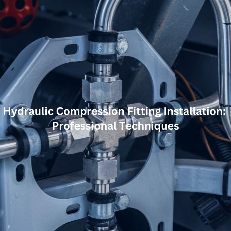
Introduction
Proper installation of hydraulic compression fittings is critical to preventing leaks and system failures. This guide is designed to provide detailed, professional techniques for installing hydraulic compression fittings, focusing on best practices and common misconceptions. It covers everything from understanding the components and types of fittings to pre-installation preparation, step-by-step installation instructions, troubleshooting, and maintenance to ensure that you are able to achieve a reliable and durable installation in your hydraulic system.
Understanding Hydraulic Compression Fittings
Components of Hydraulic Compression Fittings
Compression Nut
The compression nut is the external part that secures the fitting assembly. It tightens around the fitting body, ensuring the ferrule is compressed against the tubing. Proper tightening of the compression nut is critical to achieving a secure, leak-proof connection.
Ferrule (Ring)
The ferrule, or compression ring, is placed inside the fitting and is responsible for creating a tight seal. When the compression nut is tightened, the ferrule is compressed against the tubing, ensuring there are no gaps that could lead to leaks. Ferrules are typically made of the same material as the fitting to ensure compatibility and prevent corrosion.
Body
The body of the fitting is the central piece that holds all components together. It houses the ferrule and provides a connection point for the tubing. The body must be designed to withstand the pressures of the hydraulic system and be compatible with the fluid used.

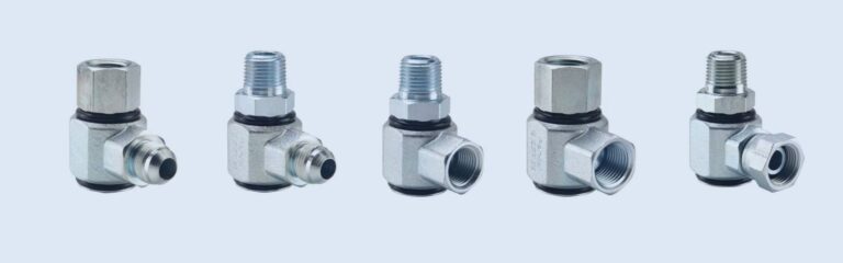
Types of Hydraulic Compression Fittings
Standard Compression Fittings
These fittings are commonly used in low to medium pressure applications. They do not require special tools for installation, making them a convenient choice for many hydraulic systems. They are often used in situations where quick and reliable connections are needed without the complexity of additional tools.
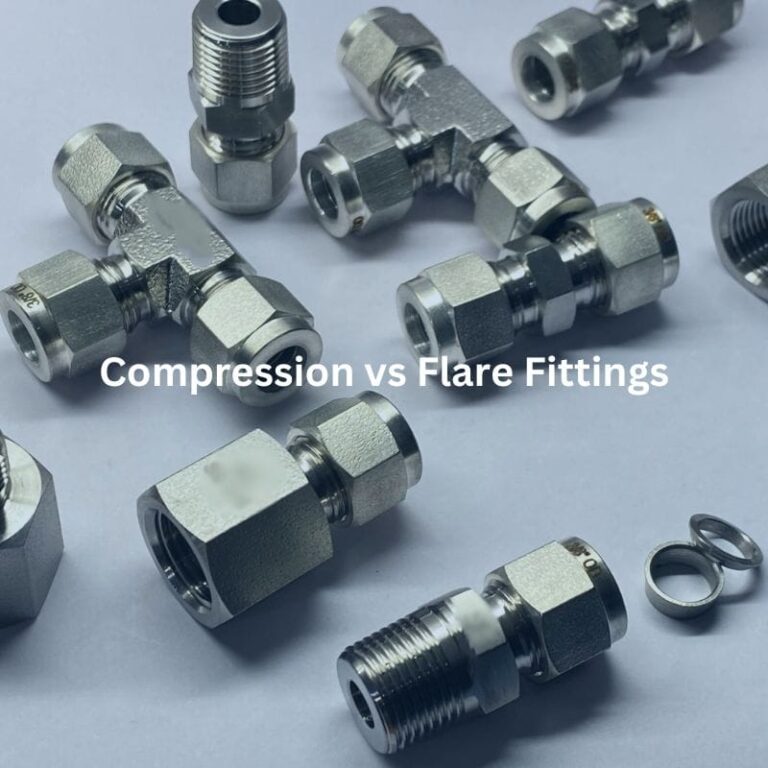
Flare Compression Fittings
Designed for high-pressure applications, flare compression fittings require the tubing to be flared using a special tool before connection. The flaring process increases the surface area for sealing, making these fittings suitable for systems that operate under higher pressures. The additional preparation step ensures a more secure connection, capable of handling greater stress.
Push-in Compression Fittings
These fittings are designed for quick and tool-free installations. They use a grip ring and an O-ring to create a seal when the tubing is pushed into the fitting. Push-in fittings are ideal for low-pressure applications and situations where ease of maintenance is crucial. They are often used in pneumatic systems and other low-pressure environments.
Material Considerations
Stainless Steel
Stainless steel is a popular choice for hydraulic compression fittings due to its excellent corrosion resistance and strength. It is suitable for a wide range of applications, including those involving aggressive fluids and high pressures. Stainless steel fittings are often used in harsh environments where durability and reliability are paramount.
Brass
Brass fittings are commonly used in applications where moderate pressure and corrosion resistance are required. Brass is easier to machine and install compared to stainless steel, making it a cost-effective option for many hydraulic systems. It is widely used in plumbing and lower-pressure hydraulic applications.
Carbon Steel
Carbon steel fittings are used in high-pressure hydraulic systems due to their strength and durability. While they provide excellent performance under high pressures, carbon steel is susceptible to corrosion and may require protective coatings or treatments to enhance its longevity. These fittings are typically used in industrial and heavy-duty applications where pressure and mechanical strength are critical.
Pre-Installation Preparation
Choosing the appropriate hydraulic compression fitting is essential to ensure the reliability and efficiency of the hydraulic system. Key factors to consider include:
System Pressure
Determine the maximum operating pressure of your system. Select fittings that are rated to handle the pressure levels to prevent leaks and failures.
Temperature
Assess the operating temperature range of your system. Different materials and designs are better suited for various temperature conditions. For example, stainless steel is ideal for high-temperature environments, while brass may be sufficient for moderate temperatures.
Fluid Type
Identify the type of fluid that will flow through the system. Compatibility with hydraulic fluid is crucial to prevent corrosion and degradation of the fittings. For instance, stainless steel is suitable for corrosive fluids, while carbon steel may be used for non-corrosive fluids.
Material and Size Compatibility
Ensure that the fitting material is compatible with the tubing material to avoid galvanic corrosion. The size of the fitting should match the tubing dimensions to ensure a proper seal.
By carefully evaluating these factors, you can select the fitting that best meets the requirements of your hydraulic system.
Tools and Equipment Needed

Proper tools and equipment are crucial for the successful installation of hydraulic compression fittings. Here is a list of essential items:
Cutting Tools
Tube Cutters: Ensure precise and clean cuts on the tubing to avoid burrs and misalignment.
Deburring Tools
Remove any burrs from the cut ends of the tubing to ensure a smooth and clean surface for the ferrule to seal against.
Wrenches
Adjustable Wrenches: Used for tightening and securing the fittings.
Torque Wrenches: Ensure that fittings are tightened to the manufacturer’s specifications to prevent over-tightening or under-tightening.
Safety Equipment
Gloves: Protect hands from sharp edges and chemicals.
Safety Glasses: Shield eyes from flying debris and fluid splashes.
Safety Precautions
Safety is paramount when working with hydraulic systems. Here are key precautions to follow:
Wear Appropriate PPE
Always wear personal protective equipment, such as gloves and safety glasses, to protect against injuries from sharp edges, high pressures, and chemical exposure.
Follow Safety Guidelines
Adhere to the safety guidelines provided by the manufacturer. Ensure that you understand the operation and potential hazards associated with the hydraulic system.
Handle with Care
Hydraulic systems operate under high pressure. Handle all components with care to avoid accidental releases of pressure, which can cause severe injuries. Ensure that the system is depressurized before starting any installation or maintenance work.
Check for Leaks
After installation, inspect all connections for leaks. Use a leak detection solution or other appropriate methods to identify any potential leaks and rectify them immediately.
Step-by-Step Installation Guide
Cutting and Preparing the Tubing
Cut the Tube
Use a Tube Cutter: For precise cuts, use a tube cutter specifically designed for hydraulic tubing. This ensures a clean, square cut, which is crucial for preventing leaks.
Ensure Precision: Align the tube cutter properly and rotate it around the tubing to create an even cut. This step is vital to avoid uneven cuts that could compromise the seal.
Deburr the Tubing
Remove Burrs: After cutting the tubing, use a deburring tool to remove any sharp edges or burrs. Burrs can prevent the ferrule from sealing properly, leading to leaks.
Create a Smooth Surface: Deburring ensures the cut end of the tubing is smooth, which is essential for a proper seal between the tubing and the ferrule.
Assembling the Fitting Components
Slide the Nut and Ferrule onto the Tubing
Correct Placement: Slide the compression nut onto the tubing first, followed by the ferrule. Ensure the ferrule is oriented correctly as per the manufacturer’s instructions. The correct placement is crucial for creating a proper seal.
Check Alignment: Ensure that the ferrule sits properly between the nut and the fitting body. Misalignment can lead to an improper seal and potential leaks.
Tightening Techniques
Hand-Tighten the Nut
Initial Tightening: Start by hand-tightening the compression nut. This step helps to ensure that the components are correctly aligned before using a wrench.
Feel for Resistance: Tighten until you feel initial resistance, indicating that the ferrule is beginning to compress against the tubing.
Wrench-Tighten
Use a Wrench: After hand-tightening, use a wrench to further tighten the nut. Turn the nut an additional 1.25 turns or as specified by the manufacturer. This ensures the ferrule compresses properly against the tubing.
Avoid Over-Tightening: Be careful not to over-tighten the nut. Over-tightening can damage the ferrule and the tubing, leading to potential leaks and system failures. The goal is to achieve a secure fit without excessive force.

Best Practices for Installation
Ensuring a Secure Fit
Verify Full Insertion of Tubing
Before tightening the compression nut, make sure the tubing is fully inserted into the fitting body. This ensures that the ferrule can effectively compress against the tubing to create a proper seal. Incomplete insertion can lead to gaps and potential leaks.
Check for Proper Alignment
Ensure the tubing is aligned correctly with the fitting. Misalignment can cause uneven pressure on the ferrule, leading to leaks and stress on the connection. Proper alignment helps maintain the integrity of the seal and extends the lifespan of the fitting.
Avoiding Common Mistakes
Over-Tightening
Over-tightening the compression nut can deform the ferrule and damage the tubing. This not only compromises the seal but can also lead to cracks and leaks. Always follow the manufacturer’s torque specifications to prevent over-tightening.
Under-Tightening
Under-tightening is equally problematic as it can result in an inadequate seal, leading to leaks and poor connection integrity. Ensure that the compression nut is tightened according to the specified number of turns or torque value provided by the manufacturer to achieve a secure fit.
Advanced Tips for Professional Installation
Use Torque Wrenches for Precise Tightening
Employing a torque wrench ensures that the compression nut is tightened to the exact torque specified by the manufacturer. This precision helps in avoiding both over-tightening and under-tightening, leading to a more reliable and consistent seal.
Utilize Compact Tools in Confined Spaces
In areas with limited space, use compact tools specifically designed for tight spaces. These tools allow for easier manipulation and accurate tightening of fittings without compromising the quality of the installation. Tools such as compact torque wrenches and small-sized wrenches can be very effective in such scenarios.
Troubleshooting and Maintenance
Regular Inspection
Regularly inspect all connections in the hydraulic system for signs of leaks. This includes checking for fluid accumulation, dampness around the fittings, or drops in system pressure. Early detection of leaks can prevent larger issues and system failures.
Disassemble and Inspect
If a leak is detected, disassemble the fitting to inspect the components. Check for visible signs of damage such as cracks in the tubing, deformed ferrules, or worn-out compression nuts. Ensure that the tubing was fully inserted during the initial installation and that the ferrule is properly seated. Reassemble the fitting carefully, ensuring all components are clean and free from debris, and retighten according to manufacturer specifications.
Regular Inspection Schedule
Establish a regular inspection schedule for your hydraulic system. Depending on the system’s usage and environmental conditions, inspections should be carried out weekly, monthly, or quarterly. Consistent monitoring helps in identifying potential issues before they become serious problems.
Prompt Replacement of Components
Replace any worn or damaged components promptly. Over time, ferrules, nuts, and tubing can wear out due to the high pressures and mechanical stresses they endure. Keeping spare parts on hand and replacing them as soon as wear is detected can significantly extend the lifespan of the entire system.
Cleaning and Lubrication
Keep the fittings and surrounding areas clean to prevent contamination from entering the system. In some cases, it may be beneficial to apply a light lubricant to the threads of the compression nut to facilitate smooth tightening and reduce wear.
System Testing
Periodically test the hydraulic system under operational conditions to ensure that all fittings are secure and functioning correctly. This can include pressure testing and leak detection tests using appropriate fluids and methods.
Conclusion
In this guide, we have explored the essential aspects of hydraulic compression fitting installation, from understanding the components and types to ensuring a secure fit, avoiding common mistakes, and performing routine maintenance. Proper selection, preparation, and installation techniques are crucial for achieving reliable and leak-free connections in hydraulic systems. Regular inspection and maintenance further enhance the system’s longevity and performance. By adhering to these professional techniques and best practices, you can ensure the efficiency and durability of your hydraulic systems, ultimately reducing downtime and maintenance costs. Consistent attention to detail and proactive maintenance are the keys to sustaining a high-performing hydraulic setup.
FAQ
What are hydraulic compression fittings?
Hydraulic compression fittings are connectors used to create leak-proof seals in hydraulic systems. They consist of a compression nut, ferrule, and fitting body, and are essential for maintaining system integrity and efficiency.
How do I select the right hydraulic compression fitting?
Consider the system’s pressure, temperature, and the type of fluid. Ensure the fitting material (e.g., stainless steel, brass) and size are compatible with the tubing and the specific requirements of your hydraulic system.
What tools are needed for installing hydraulic compression fittings?
You will need tube cutters, deburring tools, wrenches, torque wrenches, and appropriate safety equipment such as gloves and safety glasses.
What are common mistakes to avoid when installing hydraulic compression fittings?
Avoid over-tightening, which can damage the ferrule and tubing, and under-tightening, which can lead to leaks and poor connection integrity. Proper alignment and ensuring the tubing is fully inserted are also crucial.
How do I identify and fix leaks in hydraulic compression fittings?
Regularly inspect connections for signs of leaks such as fluid accumulation or dampness. If a leak is found, disassemble the fitting, inspect for damage, clean the components, and reassemble according to manufacturer specifications.
What routine maintenance practices should I follow?
Establish a regular inspection schedule, promptly replace worn or damaged components, keep fittings clean, and periodically test the system under operational conditions to ensure all connections are secure and functioning correctly.


