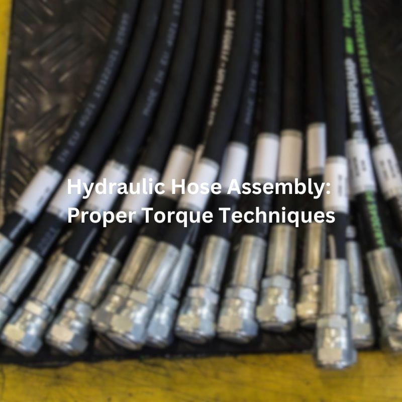
Hydraulic Hose Assembly: Proper Torque Techniques
Introduction
When hose assemblies are damaged, the integrity of the entire hydraulic system is compromised, which can result in unexpected breakdowns and increased maintenance costs. Proper torque application extends the lifespan of hoses and fittings, ensuring reliable and efficient operation. This article will delve into various torque techniques essential for hydraulic hose assemblies. It will provide detailed insights into the importance of correct torque, different types of fittings, specific torque methods, and real-world applications. By understanding and applying these techniques, professionals can avoid common pitfalls associated with improper torque.
Understanding Hydraulic Hose Assemblies
Components of Hydraulic Hose Assemblies
Hydraulic hose assemblies are intricate systems composed of several key components that work together to transport hydraulic fluid efficiently and safely. The primary components include:
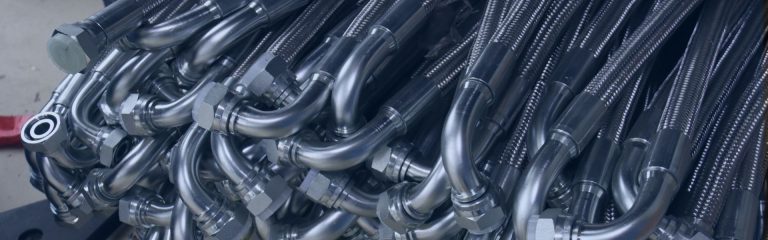
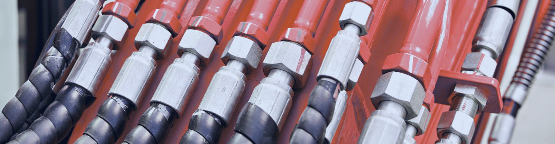
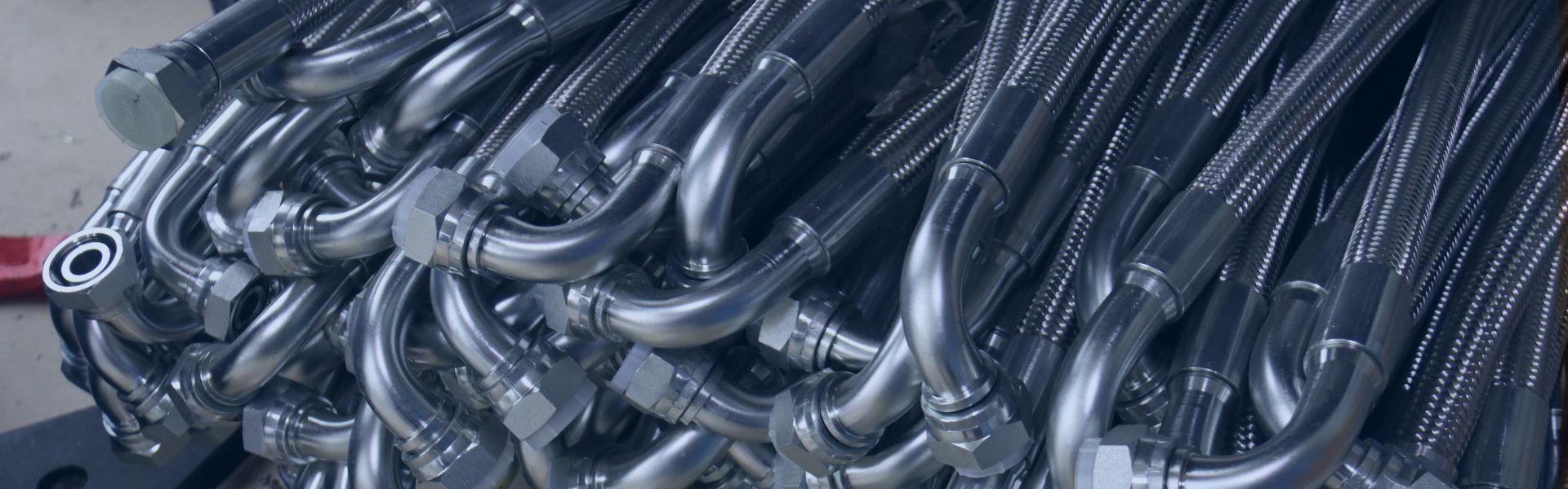
Hoses: These are flexible tubes designed to withstand high pressures and harsh operating conditions. They are typically made of reinforced rubber or thermoplastic materials, providing the necessary flexibility and durability. The hoses transport hydraulic fluid from one component to another, playing a critical role in the movement and operation of hydraulic machinery.
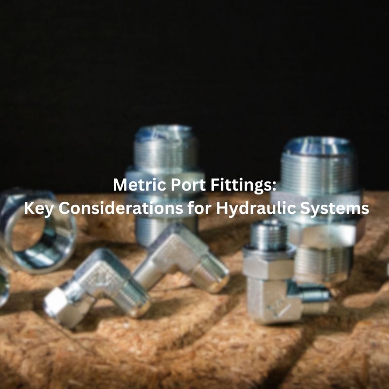
Fittings: These are connectors that attach the hose to other components in the hydraulic system. Fittings come in various types and sizes, each designed to create a secure, leak-proof connection. Common fitting types include JIC (Joint Industry Council), BSPP (British Standard Pipe Parallel), ORB (O-Ring Boss), and NPT (National Pipe Taper). Each type has its specific application and advantages, contributing to the overall efficiency of the hydraulic system.
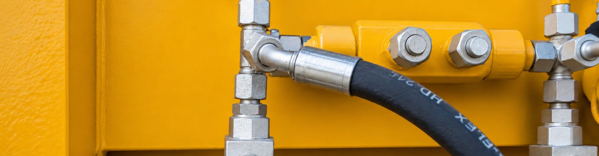
Connectors: These devices join hoses to various parts of the hydraulic system, such as pumps, cylinders, valves, and motors. Connectors ensure that the hydraulic fluid flows seamlessly between different components, maintaining the system’s integrity and performance. They must be chosen carefully to match the specifications and requirements of the hydraulic system.

Common Applications and Industries
Hydraulic hose assemblies are indispensable in numerous applications across a wide range of industries, each requiring specific characteristics and performance standards. Some of the key industries and their applications include:
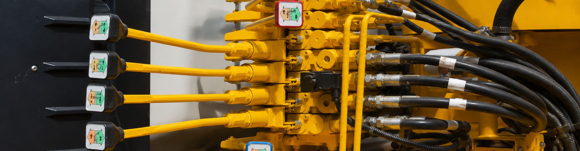
Construction: In the construction industry, hydraulic hose assemblies are crucial for operating heavy machinery and equipment such as excavators, bulldozers, cranes, and backhoes. These machines rely on hydraulic systems to perform tasks like lifting, digging, and moving materials, making the reliability and durability of hydraulic hose assemblies vital for maintaining productivity and safety on construction sites.
Manufacturing: Hydraulic hose assemblies play a significant role in manufacturing processes, especially in assembly lines and robotic systems. They are used to power hydraulic presses, conveyor belts, and other automated machinery. In this environment, precise and reliable hydraulic systems are essential for maintaining production efficiency and ensuring the consistent quality of manufactured goods.
Agriculture: In the agricultural sector, hydraulic hose assemblies are essential for operating tractors, harvesters, sprayers, and other farm equipment. These machines depend on hydraulic systems for tasks such as planting, irrigation, and harvesting. Reliable hydraulic hose assemblies help farmers maintain their equipment’s functionality and efficiency, leading to better crop yields and more efficient farming operations.
Importance of Proper Torque
Consequences of Improper Torque
Improper torque in hydraulic hose assemblies can lead to a multitude of issues that can compromise the entire hydraulic system’s performance and safety:
Leaks: One of the most immediate and noticeable consequences of improper torque is poor sealing, which can result in hydraulic fluid leaks. These leaks not only reduce system efficiency but also create potential hazards, including the risk of slipping, fire hazards from flammable fluids, and environmental contamination. Additionally, fluid leaks can lead to a loss of hydraulic pressure, rendering the system unable to perform its intended functions effectively.
Fitting Damage: Applying excessive force during assembly can damage fittings and threads. Over-torquing can deform the threads or cause cracks in the fittings, compromising their integrity and ability to form a secure, leak-proof connection. Damaged fittings are more prone to failure under high-pressure conditions, leading to increased maintenance costs and system downtime.
Hose Failure: Insufficient torque may cause hoses to detach under pressure, leading to sudden and catastrophic hose failures. This not only interrupts the operation but also poses serious safety risks to personnel and equipment. Detached hoses can whip around uncontrollably, potentially causing injury and further damage to the hydraulic system or surrounding equipment.
Benefits of Correct Torque Application
Applying the correct torque to hydraulic hose assemblies offers numerous benefits that enhance the overall performance and longevity of the hydraulic system:
Increased System Efficiency: Optimal torque ensures that all connections are secure and leak-free, allowing the hydraulic system to operate smoothly and efficiently. Properly torqued fittings minimize fluid loss and maintain consistent hydraulic pressure, which is essential for the precise operation of hydraulic machinery. This efficiency translates to better performance and productivity in various applications, from construction and manufacturing to agriculture.
Longevity of Components: Properly torqued assemblies experience less wear and tear, significantly extending the lifespan of hoses, fittings, and connectors. When components are torqued to the manufacturer’s specifications, they are less likely to suffer from deformation, cracking, or other forms of damage that can lead to premature failure. This reduces the frequency of maintenance and replacement, resulting in lower operational costs and less downtime.
Enhanced Safety: Correct torque application ensures that hydraulic systems remain safe to operate. Secure connections prevent leaks and hose detachments, reducing the risk of accidents and injuries. This is particularly important in high-pressure environments where even small leaks or failures can have serious consequences.
Reduced Maintenance Costs: By preventing leaks, fitting damage, and hose failures, correct torque application helps reduce the need for frequent repairs and maintenance. This not only lowers the cost of spare parts and labor but also minimizes system downtime, keeping operations running smoothly and efficiently.

Torque Techniques for Hydraulic Hose Assemblies
The Flats Method
The Flats Method is a straightforward technique that involves turning the fitting by a specified number of flats (the flat surfaces on the hexagonal fitting) after finger-tightening. This method provides a basic level of torque control, which is particularly useful in situations where precise torque measurements are not critical.
Procedure:
Finger-Tighten the Fitting: Begin by threading the fitting onto the hose or component by hand until it is snug. This ensures that the fitting is properly aligned and prevents cross-threading.
Use a Wrench
Turn by the Recommended Number of Flats: Using the wrench, turn the fitting by the specified number of flats, typically ranging from one to three, depending on the manufacturer’s guidelines and the type of fitting.
Applications and Limitations:
Applications: The Flats Method is useful for low-pressure applications where extreme precision is not necessary. It is commonly used in maintenance and repair scenarios where quick and reliable connections are required without the need for specialized tools.
Limitations: This method is less precise than other torque application techniques, such as using a torque wrench. It relies on the user’s ability to gauge the correct number of flats and may result in inconsistent torque application. Therefore, it is not recommended for high-pressure systems or critical applications where precise torque is essential.
The Torque Wrench Method
Importance:
The Torque Wrench Method is essential for ensuring precise torque application. It provides an accurate and consistent way to apply the correct amount of force to hydraulic fittings, reducing the risk of over-tightening or under-tightening, which can lead to leaks, fitting damage, or hose failure.
How to Use a Torque Wrench Correctly:
Set the Wrench to the Specified Torque Value: Refer to the manufacturer’s specifications for the correct torque value for the fitting you are working with. Adjust the torque wrench to this setting. It’s crucial to use a calibrated torque wrench to ensure accuracy.
Apply Steady Force Until the Wrench Clicks: Attach the torque wrench to the fitting and apply a steady, even force. The wrench will click or indicate when the specified torque value has been reached. This click is an indicator to stop applying force.
Avoid Over-Tightening by Stopping at the Click: Once the torque wrench clicks, indicating that the correct torque has been achieved, stop applying force immediately. Over-tightening can damage fittings and threads, while under-tightening can lead to leaks and hose detachment.
Advantages:
Precision: The Torque Wrench Method provides precise torque control, ensuring that each fitting is tightened to the exact specification. This is crucial for maintaining the integrity and reliability of high-pressure hydraulic systems.
Consistency: Using a torque wrench ensures that every fitting is torqued to the same specification, reducing variability and improving the overall reliability of the hydraulic assembly.
Safety: Proper torque application reduces the risk of component failure and associated safety hazards, making this method particularly important for critical applications.
Torque Values and Specifications
Recommended Torque Values for Different Fittings
Different types of hydraulic fittings require specific torque values to ensure secure and leak-free connections. Here’s an overview of the recommended torque values for common fitting types:
JIC Fittings:
These fittings have a 37-degree flare and are commonly used in fluid power applications.
Torque Values: Typically range from 18 to 23 ft-lbs (24 to 31 Nm) for 1/4-inch fittings to 90 to 110 ft-lbs (122 to 149 Nm) for 1-inch fittings.
BSPP Fittings:
These fittings feature parallel threads and seals using an O-ring or bonded washer.
Torque Values: Generally range from 15 to 20 ft-lbs (20 to 27 Nm) for 1/4-inch fittings to 100 to 120 ft-lbs (136 to 163 Nm) for 1-inch fittings.
ORB Fittings:
ORB fittings use an O-ring in a groove to provide a leak-free seal.
Torque Values: Commonly range from 12 to 15 ft-lbs (16 to 20 Nm) for 1/4-inch fittings to 70 to 80 ft-lbs (95 to 108 Nm) for 1-inch fittings.
NPT Fittings:
NPT fittings have tapered threads that seal by interference fit.
Torque Values: Typically range from 10 to 12 ft-lbs (14 to 16 Nm) for 1/4-inch fittings to 85 to 95 ft-lbs (115 to 129 Nm) for 1-inch fittings.

Factors Affecting Torque Accuracy
Several factors can affect the accuracy of torque application, which in turn impacts the reliability of hydraulic hose assemblies:
Thread Condition:
Damaged Threads: Threads that are damaged or worn can lead to inaccurate torque readings. Damaged threads may not provide the necessary resistance, causing the fitting to be over-torqued or under-torqued.
Inspection: Regularly inspect threads for signs of wear, damage, or deformation. Replace any components with compromised threads to ensure proper torque application.
Lubrication:
Proper Lubrication: Applying the correct lubricant to threads can ensure smooth tightening and accurate torque readings. Lubrication reduces friction, allowing the fitting to be tightened to the correct specification without over-torquing.
Types of Lubricants: Use lubricants recommended by the fitting manufacturer. Avoid using lubricants that can degrade the material of the fitting or the hydraulic fluid.
Cleanliness:
Dirt and Debris: Contaminants such as dirt, dust, and debris on threads can interfere with torque application. These particles can cause uneven tightening and inaccurate torque readings.
Cleaning: Always clean threads thoroughly before assembly. Use a wire brush or compressed air to remove any foreign particles from the threads. Ensure that both the fitting and the hose are clean and free from contaminants.
Step-by-Step Guide to Applying Proper Torque
Preparation and Safety Measures
Proper preparation and adherence to safety measures are essential before applying torque to hydraulic hose fittings. Here’s how to ensure optimal conditions:
Ensuring Clean Threads:
Remove Debris: Use a wire brush or compressed air to clean threads on both the fitting and the hose. Any debris, dirt, or particles can affect the accuracy of the torque application.
Inspection: Visually inspect the threads for any signs of damage or wear. Replace components with compromised threads to ensure a secure connection.
Correct Tools:
Appropriate Tools: Use tools that are specifically designed for the type of fitting you are working with. This includes the correct size and type of wrench or torque wrench.
Calibrated Torque Wrench: Ensure the torque wrench is calibrated for accurate readings. Regular calibration checks are important for maintaining precision.
Applying Torque Using the Flats Method
The Flats Method is a simple and effective way to apply torque in low-pressure situations. Here’s a detailed step-by-step guide:
Finger-Tighten the Fitting:
Begin by threading the fitting onto the hose or component by hand until it is snug. This ensures that the fitting is properly aligned and prevents cross-threading.
Mark the Starting Position:
Use a marker to indicate the starting position on the fitting. This helps you keep track of the number of flats turned.
Turn the Fitting by the Specified Number of Flats:
Use a wrench to turn the fitting by the specified number of flats. The number of flats required depends on the fitting type and manufacturer’s specifications. Typically, this ranges from one to three flats.
Visuals:
Diagrams: Visual aids can significantly help in understanding the Flats Method. Diagrams should illustrate each step, showing how to mark the starting position and measure the number of flats turned.
Applying Torque Using a Torque Wrench
The Torque Wrench Method is essential for precise torque application, especially in high-pressure systems. Follow these steps for accurate torque application:
Set the Torque Wrench to the Required Value:
Refer to the manufacturer’s specifications for the correct torque value for the fitting. Adjust the torque wrench to this setting, ensuring it is accurate and calibrated.
Attach the Wrench to the Fitting:
Secure the torque wrench onto the fitting. Make sure it is properly seated to avoid slipping during tightening.
Apply Torque Until the Wrench Clicks:
Apply steady and even force to the wrench. The torque wrench will click or indicate when the specified torque value is reached. This click signals that the correct torque has been applied.
Tips:
Ensure Even Force Application: Apply force evenly and steadily to avoid sudden movements that could lead to inaccurate torque application.
Avoid Sudden Movements: Sudden jerks or excessive force can lead to over-torquing, damaging the fitting or threads.
Conclusion
The importance of applying proper torque in hydraulic hose assemblies cannot be overstated. Correct torque application is crucial for ensuring leak-free and efficient hydraulic systems, preventing fluid leaks, component damage, and system failures. By understanding and utilizing the appropriate torque techniques, such as the Flats Method and the Torque Wrench Method, professionals can significantly enhance the reliability and performance of their hydraulic assemblies. Regular inspections and maintenance are equally important to sustain these benefits over time.
FAQ
Proper torque is crucial to ensure leak-free connections, prevent component damage, and maintain the efficiency and reliability of hydraulic systems.
Improper torque can lead to fluid leaks, damaged fittings and threads, hose detachment under pressure, and overall system inefficiency or failure.
The Flats Method involves finger-tightening the fitting and then turning it by a specified number of flats (the flat surfaces on the hexagonal fitting) using a wrench. This method is suitable for low-pressure applications.
To use a torque wrench, set it to the specified torque value, attach it to the fitting, and apply steady force until the wrench clicks, indicating the correct torque has been reached. Avoid over-tightening by stopping at the click.
Factors affecting torque accuracy include thread condition (damaged threads), lubrication (proper lubrication reduces friction), and cleanliness (dirt and debris can impact torque application).
Recommended torque values for various fittings such as JIC, BSPP, ORB, and NPT can be found in the manufacturer’s specifications or in quick reference tables and charts commonly provided in technical manuals and guidelines.


