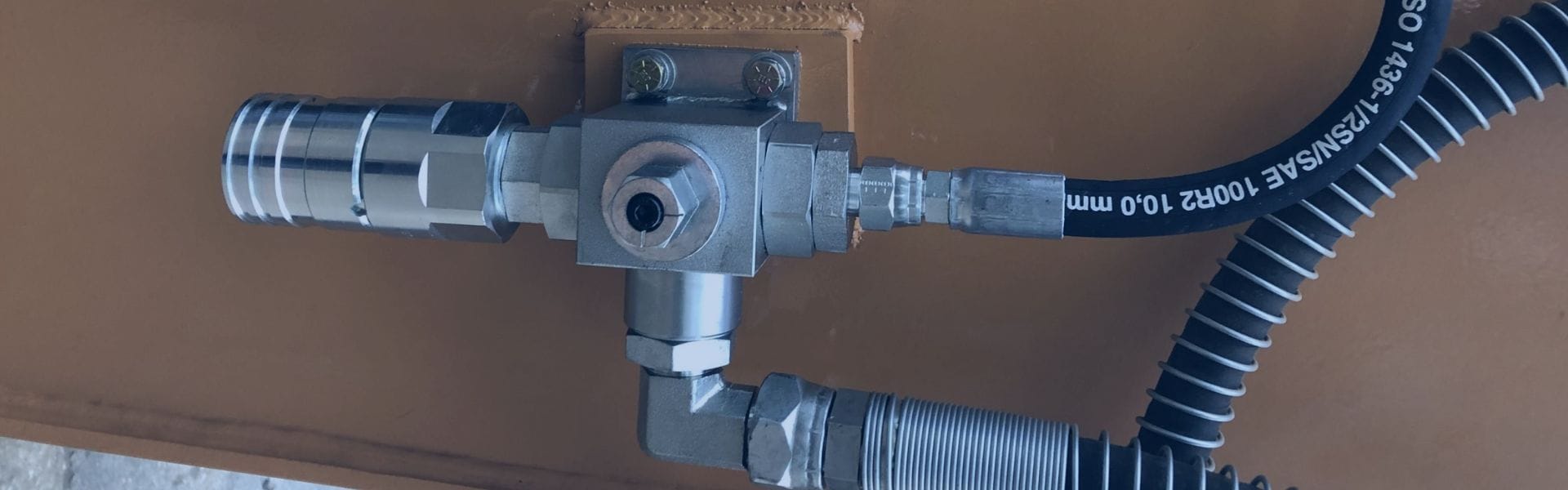
Signs of a Failing Ball Valve: Early Warning Indicators
Ball valves are a type of quarter-turn valve that uses
Ball valves are a type of quarter-turn valve that uses
Improper disposal of hydraulic hoses can lead to harmful environmental
A well-functioning ball valve ensures that fluids are controlled precisely,
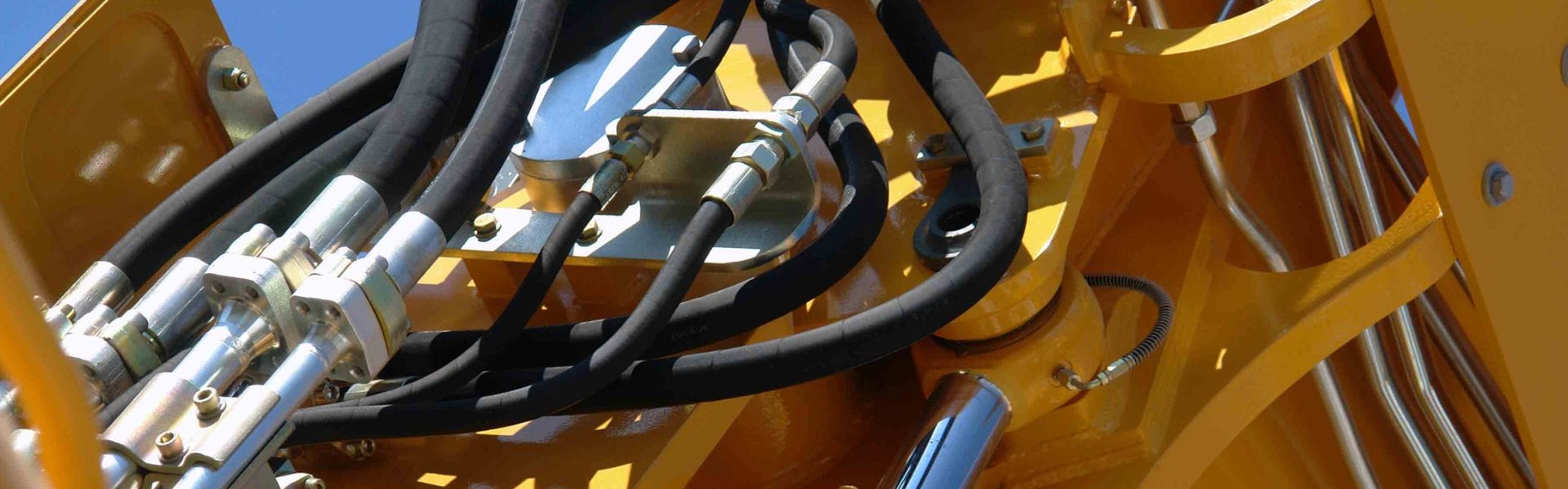
In hydraulic and industrial applications, hose assemblies are often subjected

Temperature is one of the most critical factors affecting the
Hydraulic hoses play a pivotal role in transmitting fluid power

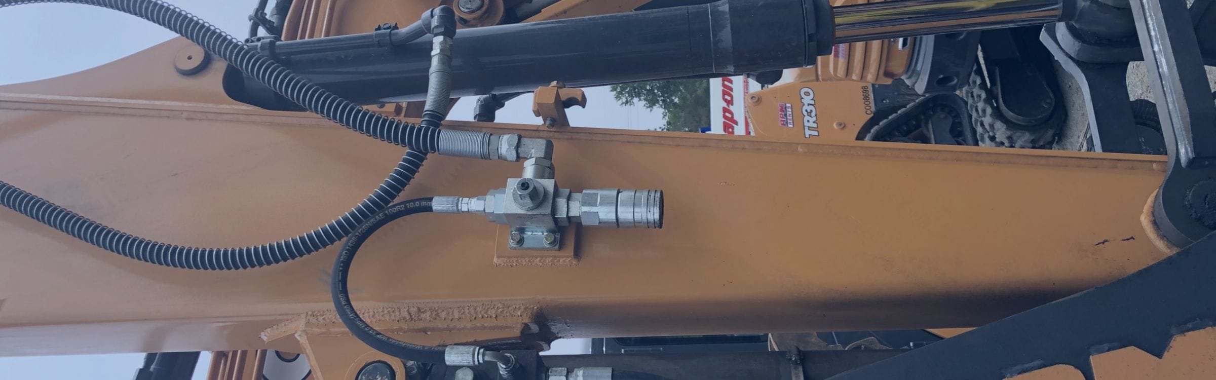
Common ball valve failures, if left unaddressed, can disrupt operations

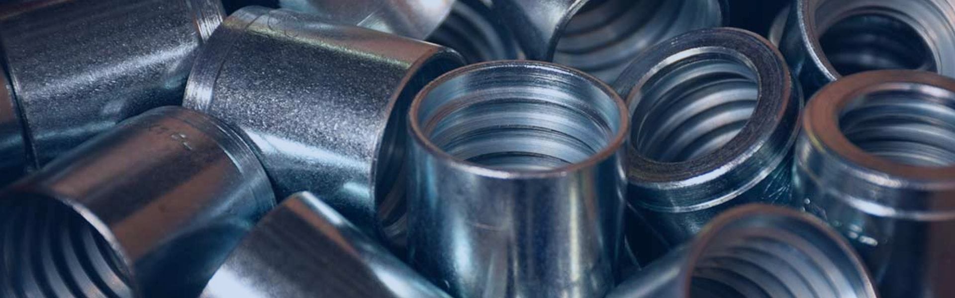
Reliable hydraulic fittings are essential to prevent leaks, corrosion, and

By sourcing hydraulic fittings from China, businesses can benefit from

The hydraulic hose manufacturing process involves a series of precise