
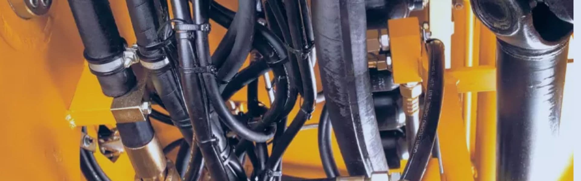
Hydraulic Hose Quality Test: What You Need to Look for
The quality of the hose directly impacts the hydraulic system’s
The quality of the hose directly impacts the hydraulic system’s

As seals and internal components degrade, the valve’s ability to

The slip ball valve is designed for easy installation and

The defining feature of a 3-way ball valve is its

Internal leakage occurs when the valve fails to completely seal,

Ball valves use a spherical ball with a hole (or

While ball valves are known for their ability to provide
Core selection is not just a technical detail but a
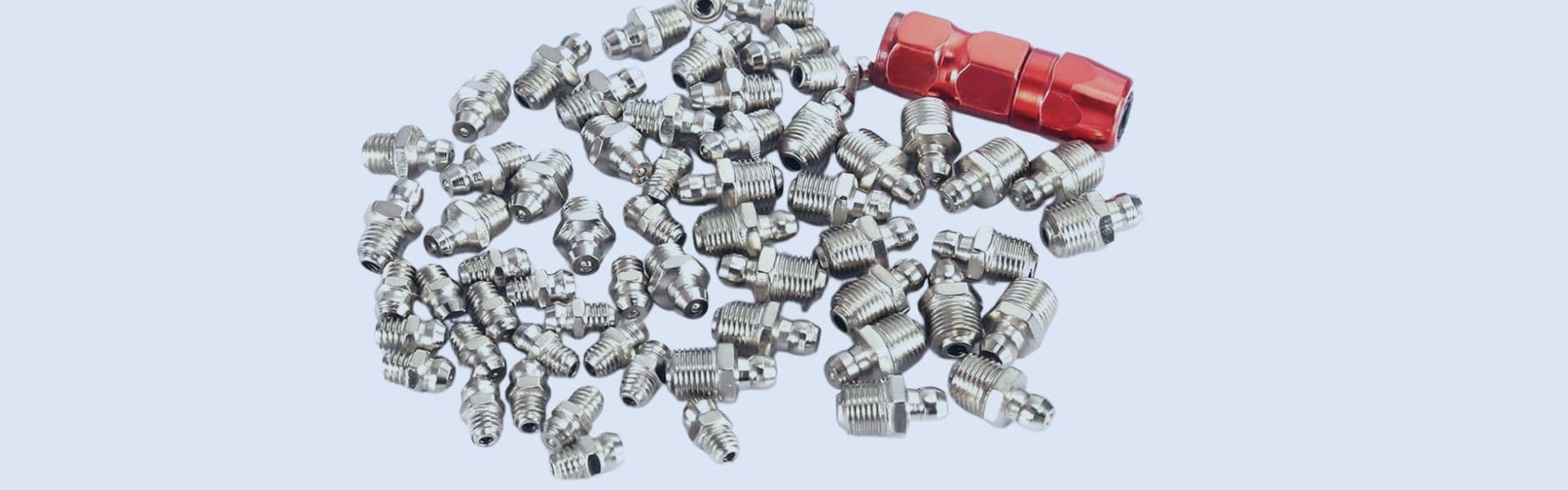
Grease fittings are typically located at the joints or pivot points
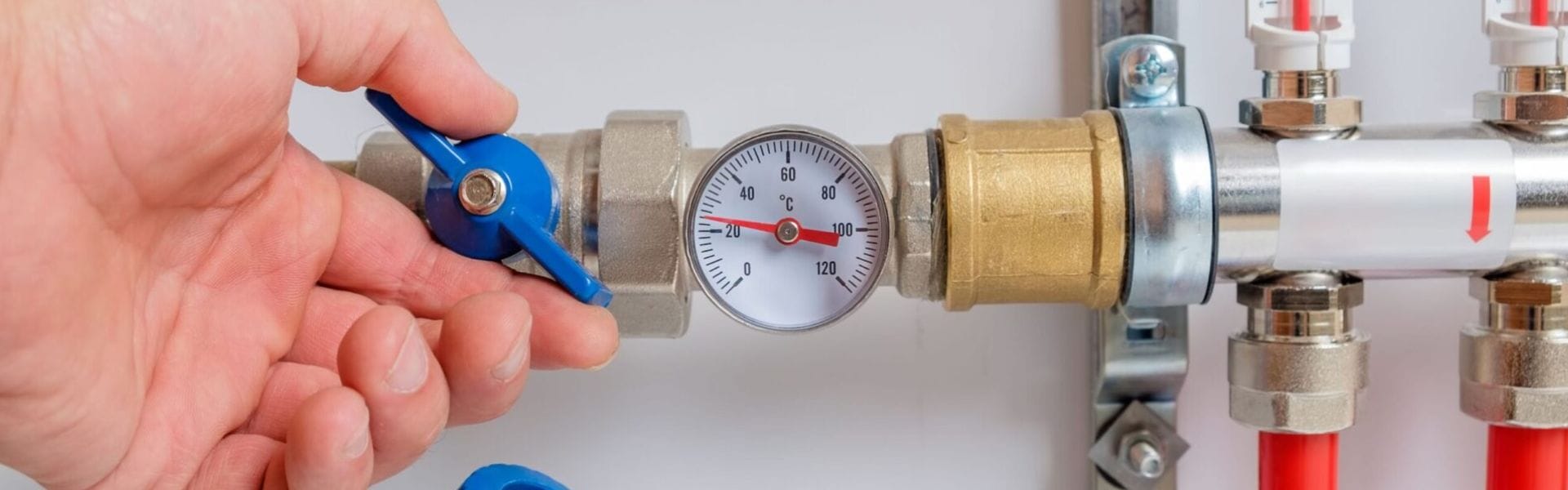
Ball valves are critical components in fluid systems, ensuring precise