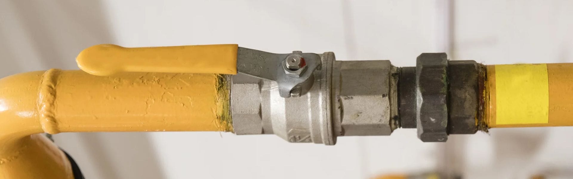
Unlocking the Ball Valve Open Position: Tips You Need to Know
Knowing the open position of a ball valve is essential
Knowing the open position of a ball valve is essential
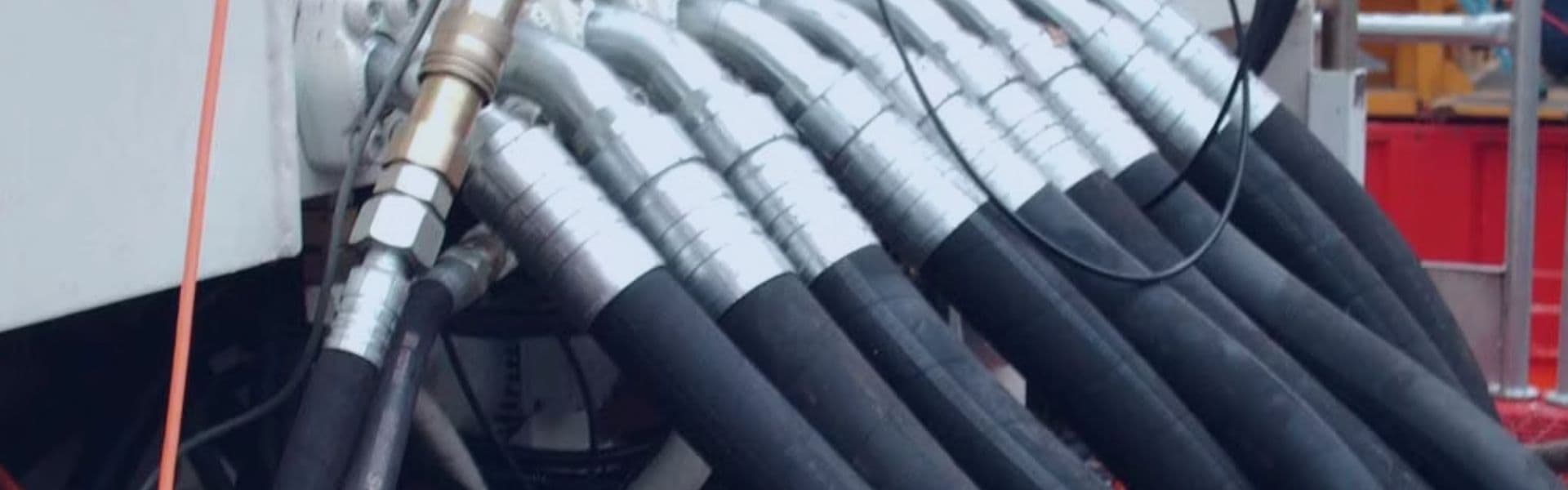
A hydraulic hose mandrel serves as the backbone of the

In hydraulic systems, grease fittings are typically used to keep

High-pressure sandblasting requires specialized equipment designed to handle intense conditions.

Proper installation of a ball valve is essential for achieving

Whether controlling the flow of water in a home or

A leaking ball valve is more than just an inconvenience—it

Ball valves come in a range of designs, each tailored

Choosing between a globe valve vs ball valve depends on

Choosing between a gate valve vs ball valve depends on