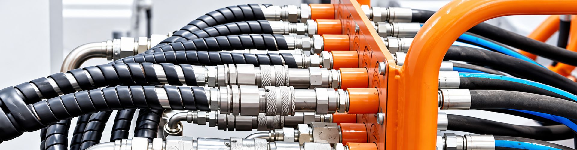
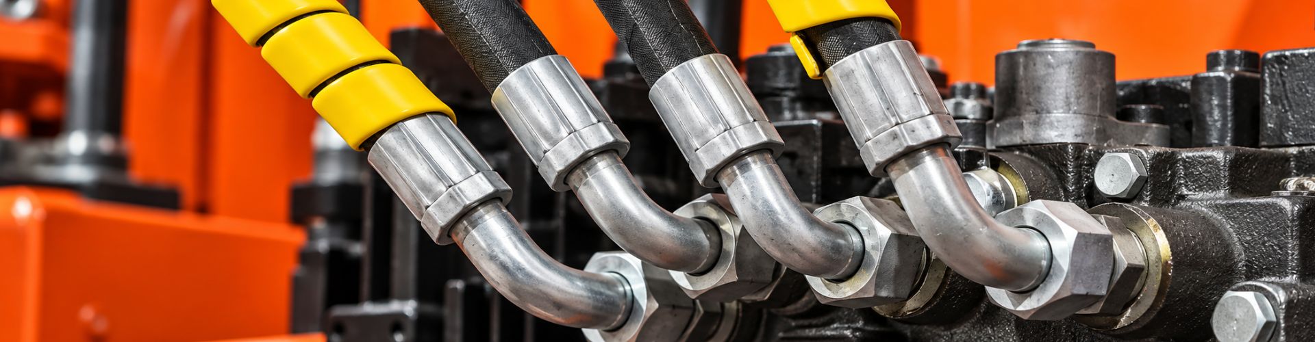
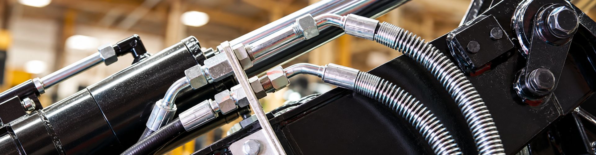
Hydraulic Hose Inner Tube Material Selection banner

Hydraulic Hose Inner Tube: Material Selection Tips

In the demanding world of chemical processing and industrial hydraulics, the integrity and longevity of hydraulic hose systems are paramount. A critical, yet often overlooked, component is the inner tube of the hydraulic hose. This seemingly simple layer is the primary barrier between the conveyed fluid and the rest of the hose assembly, making its material selection a decisive factor in operational safety, efficiency, and cost-effectiveness. This comprehensive guide is tailored for chemical industry engineers and material selection experts, aiming to demystify the complexities of inner tube material compatibility. We will explore how choosing the right material can prevent catastrophic failures, mitigate media corrosion, combat material aging, resolve compatibility issues, and eliminate fluid contamination, ultimately safeguarding your investments and operational continuity.

Understanding Hydraulic Hose Inner Tubes: The Unsung Hero of Fluid Conveyance

The Fundamental Role of the Inner Tube

The inner tube, also known as the core tube or liner, is the innermost layer of a hydraulic hose. Its primary function is to contain the conveyed fluid and prevent its permeation into the reinforcement layers or outer cover of the hose. This layer is in direct contact with the hydraulic fluid or chemical medium, making its material composition the most critical determinant of the hose’s chemical resistance and overall performance.

Hydraulic hose components design Topa

Anatomy of a Hydraulic Hose

While the inner tube is central to media compatibility, it’s essential to understand its place within the complete hydraulic hose assembly. A typical hydraulic hose comprises several layers, each serving a distinct purpose:

Key Inner Tube Materials: Properties and Applications

Selecting the appropriate inner tube material requires a detailed understanding of the properties of various elastomers and thermoplastics. Here, we delve into the characteristics of commonly used materials, highlighting their strengths, limitations, and typical applications.

NBR (Nitrile Butadiene Rubber): The Workhorse of Hydraulic Systems

Nitrile Butadiene Rubber, commonly known as NBR or Buna-N, is one of the most widely used elastomers for hydraulic hose inner tubes. Its popularity stems from its excellent balance of properties, particularly its resistance to petroleum-based fluids.

Characteristics of NBR:

Limitations of NBR:

Typical Applications of NBR:

hydraulic hose material Topa

FKM (Fluoroelastomer/Viton): The High-Performance Champion

Fluoroelastomers, commonly known as FKM or by the brand name Viton (a registered trademark of Chemours), are a class of synthetic rubbers renowned for their exceptional chemical and heat resistance. FKM is the material of choice for demanding applications where conventional elastomers fall short.

Characteristics of FKM:

Limitations of FKM:

Typical Applications of FKM:

EPDM (Ethylene Propylene Diene Monomer): The Water and Steam Specialist

EPDM is a synthetic rubber known for its excellent resistance to water, steam, ozone, and a variety of polar fluids. It is a versatile material, particularly suited for applications where petroleum-based fluids are not present.

Characteristics of EPDM:

Limitations of EPDM:

Typical Applications of EPDM:

  • Automotive cooling systems

Other Inner Tube Materials: Expanding the Horizon

While NBR, FKM, and EPDM are the most common, other materials are used for specialized hydraulic hose inner tubes, each offering unique advantages:

Navigating Chemical Compatibility: A Strategic Approach

The Importance of a Comprehensive Compatibility Chart

Selecting the correct inner tube material is a meticulous process that requires more than just a general understanding of material properties. It demands a detailed assessment of the specific chemical media involved, including their concentration, temperature, and pressure. A comprehensive chemical compatibility chart is an indispensable tool in this process, providing a quick reference for the suitability of various elastomers with different chemicals.

Factors Influencing Compatibility

Beyond the primary chemical composition, several other factors can significantly influence the compatibility between the inner tube material and the conveyed fluid:

Practical Considerations for Material Selection

While chemical compatibility is paramount, a holistic approach to material selection considers all operating conditions. This includes:

Mitigating Common Pain Points: Strategies for Success

Addressing the customer pain points identified earlier requires a strategic approach to material selection and system management.

Addressing Media Corrosion and Material Aging

Resolving Compatibility Issues and Preventing Media Contamination

No matter what material of hydraulic hose is needed, contact Topa and we can customize the most suitable product for your needs, send your request now!


FAQ

What is the most important factor in selecting a hydraulic hose inner tube material?

The most important factor is the chemical compatibility of the inner tube material with the conveyed fluid.

Can I use NBR with brake fluid?

No, NBR is generally not recommended for use with glycol-based brake fluids; EPDM is typically preferred.

Why is FKM more expensive than NBR or EPDM?

FKM is more expensive due to its superior chemical and high-temperature resistance, requiring specialized manufacturing processes.

What happens if I use an incompatible inner tube material?

Using an incompatible material can lead to media corrosion, material aging, leaks, and fluid contamination, causing system failure.

Are chemical compatibility charts always 100% accurate?

Chemical compatibility charts are general guides; actual performance can vary based on temperature, concentration, pressure, and fluid mixtures.

Should I conduct my own compatibility testing?

Yes, for critical or unique applications, conducting custom compatibility testing is highly recommended to ensure absolute confidence.

References

  1. Trelleborg Fluid Handling Solutions. (n.d.). EPDM or NBR.
  2. Marco Rubber & Plastics. (n.d.). O-Ring Chemical Compatibility Guide.
  3. WARCO. (n.d.). Understanding Fluoroelastomers (FKM).
  4. Minor Rubber. (n.d.). Rubber Chemical Compatibility Chart & Resistance Guide.
  5. Graco Inc. (n.d.). Chemical Compatibility Guide.
Hydraulic Hose Layer Structure Analysis banner

Hydraulic Hose Layer Structure Analysis: A Technical Guide

Selecting the appropriate hydraulic hose is paramount for optimizing the performance, reliability, and cost-effectiveness of any hydraulic system. A critical, yet often overlooked, aspect of hydraulic hose selection is its internal layer structure. This comprehensive guide delves into the intricacies of single-layer, double-layer, and multi-layer hydraulic hoses, providing technical engineers and product selection personnel with the knowledge to make informed decisions.

Understanding Hydraulic Hose Construction

A hydraulic hose is a complex engineered component designed to safely and efficiently transmit hydraulic fluid under varying pressures and temperatures. Its construction typically comprises three primary layers, each serving a distinct purpose:

Core Tube: The Fluid Conduit

The innermost layer, the core tube, is responsible for containing and conveying the hydraulic fluid. Its material composition is crucial for chemical compatibility with the fluid, as well as resistance to heat and pressure. Common materials include synthetic rubber (such as Nitrile, Neoprene, or EPDM) and thermoplastics (like Nylon or Polyester). The choice of material directly impacts the hose’s temperature range and its ability to withstand degradation from the hydraulic fluid.

Reinforcement Layers: The Strength Behind the Pressure

The reinforcement layers are the backbone of the hydraulic hose, providing the necessary strength to withstand internal pressure and external forces. These layers are typically made from high-tensile materials, such as steel wire or synthetic fibers, and are applied in various configurations to achieve different pressure ratings and flexibility characteristics. The number and type of reinforcement layers are the primary determinants of a hose’s working pressure and burst strength.

Hydraulic Hose size Selection

Single-Layer Reinforcement Hoses

Single-layer reinforcement hoses, often referred to as one-wire braid (1WB) hoses (e.g., SAE 100R1), feature a single braid of high-tensile steel wire or textile fiber. These hoses are generally designed for low to medium-pressure applications. Their simpler construction offers greater flexibility and a smaller bend radius compared to multi-layered hoses, making them suitable for applications with tight routing constraints. They are commonly found in:

Double-Layer Reinforcement Hoses

Double-layer reinforcement hoses, commonly known as two-wire braid (2WB) hoses (e.g., SAE 100R2), incorporate two braids of high-tensile steel wire. This additional layer significantly increases the hose’s working pressure capacity and burst strength, making them suitable for a wider range of medium to high-pressure hydraulic systems. While less flexible than single-layer hoses, they still offer a good balance of pressure capability and maneuverability. They are widely used in:

Multi-Layer Reinforcement Hoses

Multi-layer reinforcement hoses, often referred to as multi-spiral hoses, feature multiple (typically four or six) spiraled layers of high-tensile steel wire. This construction provides exceptional pressure resistance, making them ideal for very high-pressure and heavy-duty applications with significant pressure surges. While offering superior strength, multi-spiral hoses are generally less flexible and have a larger bend radius compared to braided hoses. Their primary applications include:

Outer Cover: Protection from the Elements

The outermost layer, the outer cover, serves as a protective shield for the reinforcement layers and core tube from external damage. It guards against abrasion, ozone, UV radiation, chemicals, and environmental factors. Common cover materials include synthetic rubber compounds (e.g., SBR, Neoprene) and thermoplastic elastomers (TPE). The choice of cover material depends on the operating environment and the level of protection required against external aggressors. Specialized covers can offer enhanced abrasion resistance, flame retardancy, or weatherability.

Performance Comparison of Different Layer Configurations

Choosing the right hydraulic hose layer configuration is a balancing act between various performance parameters. Each layer type offers distinct advantages and disadvantages that must be carefully considered based on the specific application requirements.

Pressure Rating and Burst Strength

This is arguably the most critical factor in hydraulic hose selection. The reinforcement layers directly dictate the hose’s ability to withstand internal pressure.

Flexibility and Bend Radius

Flexibility refers to the ease with which a hose can be bent, while bend radius is the minimum radius to which a hose can be bent without kinking or damaging its structure. These factors are crucial for routing in confined spaces and for applications requiring dynamic movement.

Multi-Layer Hydraulic hoses

Abrasion Resistance and Durability

While the outer cover primarily provides abrasion resistance, the overall durability of the hose is also influenced by its internal structure and the materials used in its reinforcement layers.

Temperature Range and Chemical Compatibility

The core tube material primarily determines the temperature range and chemical compatibility, but the overall hose construction must also be able to withstand these conditions.

Table 1: Hydraulic Hose Layer Configuration Comparison

Hydraulic Hose Layer Selection Decision Tool

Making the right choice for hydraulic hose layer configuration can significantly impact system performance, reliability, and cost. To simplify this process, engineers and product selection personnel can utilize a structured decision-making approach based on key application factors.

Key Factors for Selection

Before selecting a hydraulic hose, consider the following critical factors, often remembered by the acronym STAMPED:

Decision Matrix for Optimal Layer Configuration

Based on the STAMPED factors, particularly pressure and application, the following decision matrix can guide the selection of the optimal layer configuration:

Table 2: Hydraulic Hose Layer Selection Decision Matrix

Note: This matrix provides a general guideline. Specific SAE standards (e.g., SAE 100R1, 100R2, 100R12) should always be consulted for detailed specifications and to ensure compliance with industry requirements. Always consider the most demanding factor in your application when making a selection. For instance, if a hose operates at medium pressure but in an extremely abrasive environment, prioritize the abrasion resistance over just the pressure rating.

Future Trends in Hydraulic Hose Technology

The hydraulic hose industry is continuously evolving, driven by the demands for higher performance, increased efficiency, greater durability, and enhanced sustainability. Several key trends are shaping the future of hydraulic hose technology, promising exciting advancements for engineers and end-users alike.

Advanced Materials

Research and development are focused on new materials for both the core tube and reinforcement layers. This includes:

Smart Hose Technology and Condition Monitoring

The integration of sensors and IoT (Internet of Things) capabilities into hydraulic hoses is a significant emerging trend. “Smart hoses” can:

Eco-Friendly and Sustainable Solutions

Environmental concerns are pushing the industry towards more sustainable practices:

These future trends indicate a move towards hydraulic hoses that are not only stronger and more durable but also smarter, lighter, more flexible, and more environmentally responsible. As these technologies mature, they will offer significant benefits in terms of system efficiency, reliability, safety, and overall cost of ownership.

Conclusion

Selecting the optimal hydraulic hose layer configuration is a critical engineering decision that directly impacts the performance, reliability, and cost-effectiveness of hydraulic systems. By thoroughly understanding the characteristics of single-layer, double-layer, and multi-layer hoses, and by meticulously considering factors such as pressure, flexibility, and environmental conditions, engineers and product selection personnel can make informed choices that lead to significant improvements in system longevity and efficiency.

If you need a different hydraulic hose or need to customize a higher quality hydraulic product, contact Topa and we can provide fast service!


FAQ

What is the primary function of the reinforcement layers in a hydraulic hose? 

The reinforcement layers provide the strength to withstand internal pressure.

When should I choose a single-layer hydraulic hose? 

Choose a single-layer hose for low to medium-pressure applications requiring high flexibility.

What is the main advantage of multi-layer hydraulic hoses? 

Multi-layer hoses offer superior pressure resistance for very high-pressure applications.

Why are hydraulic fittings and seals important? 

They ensure leak-free connections and maintain system pressure.

What does the STAMPED acronym stand for in hose selection? 

STAMPED stands for Size, Temperature, Application, Media, Pressure, Ends, and Delivery.

How can I prevent leaks in hydraulic systems? 

Prevent leaks by ensuring cleanliness, proper lubrication, correct torque, and regular inspection.

References

[1] Muncie Power Products. (2024, May 14). Hydraulic Hose Basics: Types, Laylines, and Pressure Ratings.

[2] HOS. (2024, June 21). The Benefits of Multi-Spiral Hose.

[3] Pirtek USA. (2024, September 27). Decoding the Quality Standards and Certifications of High-Temperature Hydraulic Hoses.

[4] Hydraulic Hoses. (2024, June 5). The Future of Hydraulic Hose Technology: 2024 and Beyond.

Preventing 90% Bend Fatigue Failure An Installation Guide

Preventing 90% Bend Fatigue Failure: An Installation Guide

Hydraulic hoses, often overlooked in their apparent simplicity, are critical conduits for power transmission. However, their effectiveness and lifespan are profoundly influenced by how they are installed, particularly concerning their bend radius. This comprehensive guide delves into the critical aspects of hydraulic hose bend radius requirements and the equally vital role of hydraulic connector seals.

The Critical Role of Bend Radius in Hydraulic Systems

The bend radius of a hydraulic hose is not merely a geometric constraint; it is a fundamental design parameter that directly impacts the hose’s performance, durability, and safety. When a hydraulic hose is bent beyond its specified minimum bend radius, it undergoes excessive stress and strain, leading to a cascade of detrimental effects. This over-bending can cause the reinforcement layers within the hose—whether textile braid, wire braid, or spiral wire—to separate, kink, or even fracture. The inner tube can also suffer damage, leading to fluid leakage and contamination of the hydraulic system. Such damage often manifests as bend fatigue failure, a common culprit behind premature hose degradation and system downtime.

Proper bend radius adherence is crucial for several reasons:

In essence, the bend radius is a critical determinant of a hydraulic hose’s operational lifespan and the overall reliability of the hydraulic system. Overlooking this fundamental principle can lead to costly failures, reduced efficiency, and significant safety hazards. Therefore, a thorough understanding and diligent application of bend radius guidelines are indispensable for any professional involved in the design, installation, or maintenance of hydraulic systems.

Understanding Minimum Bend Radius: Definition and Measurement

The minimum bend radius (MBR) of a hydraulic hose is a crucial specification provided by manufacturers, representing the smallest radius to which a hose can be bent without causing damage or significantly reducing its service life. It is a fundamental parameter that installation engineers and designers must strictly adhere to.

hose bend fatigue fail

Definition of Minimum Bend Radius

The minimum bend radius is typically measured to the inside edge of the hose bend, not the centerline. This distinction is important because the inner wall of the hose experiences the greatest compression, while the outer wall experiences the greatest tension during bending. The MBR ensures that neither the inner tube nor the reinforcement layers are subjected to stresses beyond their design limits, which could lead to kinking, collapse, or premature fatigue.

It’s important to differentiate between static and dynamic bend radii:

How Minimum Bend Radius is Measured

The measurement of the minimum bend radius is a standardized process conducted by manufacturers under controlled laboratory conditions. While the exact methodology may vary slightly between manufacturers, the core principle remains consistent: determining the smallest radius at which the hose can be bent without exhibiting signs of damage or permanent deformation.

Common methods for measuring MBR involve:

It is crucial for users to rely on the manufacturer’s published MBR specifications, as these values are derived from rigorous testing and are specific to the hose’s construction, materials, and intended application. Attempting to determine the MBR empirically in the field without proper equipment or knowledge can lead to inaccurate assessments and potential hose failure.

Factors Influencing Hydraulic Hose Bend Radius

The minimum bend radius of a hydraulic hose is not a universal constant; it is a dynamic value influenced by several key factors related to the hose’s construction, materials, and intended application. Understanding these influencing factors is crucial for selecting the appropriate hose for a given application and ensuring its longevity.

Hose Construction and Reinforcement Layers

The internal structure and reinforcement layers are perhaps the most significant determinants of a hydraulic hose’s flexibility and, consequently, its minimum bend radius. Different types of reinforcement offer varying degrees of flexibility and pressure resistance:

Hydraulic Hose Bend Radius Design

Inner Diameter (ID) of the Hose

There is a direct correlation between the inner diameter (ID) of a hydraulic hose and its minimum bend radius. Generally, the larger the inner diameter of the hose, the larger its required minimum bend radius. This is because a larger hose has a greater cross-sectional area, and bending it to a tight radius would induce more significant stress on its materials. For example, a 1-inch ID hose will have a considerably larger MBR than a 1/4-inch ID hose, even if both have the same reinforcement type.

Operating Pressure and Temperature

While not directly influencing the inherent minimum bend radius of the hose material, operating pressure and temperature can indirectly affect the effective bend radius in an application. Hoses operating under high pressure experience increased internal stress, which can exacerbate the effects of over-bending. Some manufacturers may recommend a slightly larger bend radius for hoses consistently operating at or near their maximum working pressure to extend service life. Similarly, extreme temperatures (both high and low) can affect the flexibility of the hose materials, potentially requiring adjustments to bend radius considerations. For instance, hoses can become stiffer in very cold environments, making them more susceptible to damage if bent too tightly.

Application Type (Static vs. Dynamic)

As discussed earlier, whether the hose is used in a static or dynamic application significantly impacts the required bend radius. Dynamic applications, where the hose is constantly flexing, demand a larger minimum bend radius to account for the continuous fatigue cycles. Ignoring this distinction is a common cause of premature hose failure in machinery with moving parts.

External Factors and Installation Practices

Improper installation practices can also lead to effective bend radii that are smaller than recommended, even if the hose itself is capable of tighter bends. Factors such as:

Understanding these factors allows engineers to make informed decisions during the design and installation phases, ensuring that the selected hydraulic hose and its routing are appropriate for the specific application, thereby maximizing its lifespan and system reliability.

Calculating Minimum Bend Radius: Methods and Considerations

Calculating the minimum bend radius (MBR) for a hydraulic hose is not typically a calculation performed by the end-user or installer in the field. Instead, the MBR is a specification provided by the hose manufacturer, determined through rigorous testing and adherence to industry standards. The role of the installation engineer or designer is to adhere to this specified MBR, not to calculate it from scratch.

Manufacturer-Provided MBR

The most reliable and accurate source for a hydraulic hose’s minimum bend radius is the manufacturer’s technical data sheet or catalog. These documents will list the MBR for each specific hose type, size (inner diameter), and pressure rating. It is imperative to consult these specifications for every hose used in a hydraulic system. Ignoring these published values is a primary cause of premature hose failure.

Manufacturers typically express the MBR in inches or millimeters. For example, a specification might state: “Minimum Bend Radius: 4.0 inches.” This means that the hose should never be bent to a radius smaller than 4.0 inches, measured to the inside curve of the bend.

General Guidelines and Rules of Thumb (with Caution)

While manufacturer specifications are paramount, some general guidelines and rules of thumb exist, primarily for conceptual understanding or preliminary design. These should never replace the manufacturer’s data.

One common, albeit simplified, approach for estimating a static MBR is to multiply the hose’s inner diameter (ID) by a factor. This factor varies significantly based on hose construction:

Example: If a hose has an inner diameter of 1 inch and a typical bend radius ratio of 8, its minimum bend radius would be 8 inches (1 inch * 8).

Important Caveat: These are very rough estimates and should only be used for initial planning. The actual MBR can be influenced by the specific materials, manufacturing processes, and exact reinforcement design, making manufacturer data indispensable.

Considerations for Dynamic Applications (Bend Factor)

For hoses in dynamic applications, where continuous flexing occurs, the effective MBR must be larger than the static MBR. Manufacturers often provide a bend factor” or “dynamic bend radius multiplier” to account for this. This factor typically ranges from 1.1 to 1.5.

Dynamic MBR = Static MBR * Bend Factor

For instance, if a hose has a static MBR of 5 inches and is used in a dynamic application with a bend factor of 1.2, the effective dynamic MBR for installation should be 6 inches (5 inches * 1.2). This ensures that the hose is not over-stressed during its operational cycles.

Practical Application and Measurement in the Field

Once the appropriate MBR is known, it must be correctly applied during installation. Here are practical considerations:

By diligently applying these principles and always referring to manufacturer specifications, engineers can ensure that hydraulic hoses are installed in a manner that maximizes their service life and contributes to the overall reliability and safety of the hydraulic system

Best Practices for Installation and Maintenance

Proper installation and diligent maintenance are paramount to maximizing the lifespan of hydraulic hoses and ensuring the leak-free operation of hydraulic systems. Even with the correct hose and fittings, poor practices can lead to premature failure, costly downtime, and safety hazards. Adhering to these best practices will significantly enhance system reliability and longevity.

Hose Routing and Installation Best Practices

hose bend fatigue failure

Maintenance and Inspection

By integrating these best practices into your installation and maintenance protocols, you can significantly extend the service life of hydraulic hoses and seals, ensuring the safe, efficient, and reliable operation of your hydraulic systems.

Conclusion

Understanding and diligently applying the principles of hydraulic hose bend radius and proper connector sealing are fundamental to the design, installation, and maintenance of reliable and efficient hydraulic systems. Adherence to these best practices transforms potential points of failure into robust, high-performing elements of any hydraulic circuit, ensuring long-term success and operational excellence.

If you have any hydraulic hose needs, contact us, Topa can provide the optimal hose products!


FAQ

What happens if I bend a hydraulic hose tighter than its minimum bend radius?

Bending a hydraulic hose tighter than its minimum bend radius can cause internal damage to the hose, leading to kinking, reduced flow, premature wear, and eventual failure due to fatigue.

How do I find the minimum bend radius for a specific hydraulic hose?

Always refer to the manufacturer’s technical data sheet or catalog for the precise minimum bend radius specifications for your specific hydraulic hose type and size.

Is the minimum bend radius the same for static and dynamic applications?

No, the minimum bend radius for dynamic (flexing) applications is typically larger than for static (fixed) applications to account for continuous fatigue cycles. Manufacturers often provide a ‘bend factor’ for dynamic use.

What is the most common cause of hydraulic hose failure?

While many factors contribute, improper installation, including exceeding the minimum bend radius and twisting the hose, is a very common cause of premature hydraulic hose failure.

Why are O-Ring Face Seal (ORFS) fittings preferred in many hydraulic applications?

ORFS fittings are highly favored for their superior leak-free performance, especially in high-pressure and vibration-prone applications, due to their soft, reliable O-ring seal that is resistant to over-tightening and vibration.

How important is fluid compatibility when selecting O-rings?

Fluid compatibility is critical; using an incompatible O-ring material with the hydraulic fluid can lead to seal degradation, swelling, shrinking, or hardening, resulting in leaks and premature failure.

References

[1] StrongFlex. Bend Radius Guidelines for Hydraulic Hose.

[2] Fluid Power Journal. Hydraulic Hose Maintenance.

[3] LinkedIn. What are the common types of hydraulic fitting seals?

[4] Royal Brass and Hose. Seal the Deal: Your Guide to O-Ring Types.

[5] Hose Assembly Tips. Minimum bend radius for hydraulic hoses.

Hydraulic Hose Temp Resistance for Harsh Work Sites banner

Hydraulic Hose Temp Resistance for Harsh Work Sites

Hydraulic systems are the backbone of countless industrial, mobile, and aerospace applications, providing the power and precision necessary for critical operations. From heavy machinery operating in scorching deserts to aircraft flying through frigid stratospheres, these systems rely on the integrity of their components to function reliably. Among these, hydraulic hoses and their connector seals are paramount, acting as the lifelines that transmit fluid power. However, their performance is acutely sensitive to temperature, an often-underestimated factor that can lead to premature failure, costly downtime, and even catastrophic safety incidents. This article, aimed at extreme environment application engineers and material scientists, delves into the intricate relationship between temperature and hydraulic hose performance, offering insights into degradation mechanisms, material science advancements, and practical mitigation strategies.

The Unseen Enemy: Temperature’s Impact on Hydraulic Hose Performance

Temperature is a pervasive and often insidious factor that significantly influences the performance and longevity of hydraulic hoses. Unlike immediate mechanical stresses, thermal degradation can be a gradual process, silently compromising the hose’s structural integrity until a sudden and often catastrophic failure occurs. Both excessively high and extremely low temperatures, as well as rapid fluctuations between them, pose unique challenges to the polymeric and elastomeric materials that constitute hydraulic hoses.

High-Temperature factory

High-Temperature Aging: The Silent Degradation

High temperatures accelerate chemical reactions within the hose materials, leading to a phenomenon known as thermal aging. This process primarily affects the elastomeric compounds used in the inner tube and outer cover, as well as the adhesive layers bonding the reinforcement plies. At elevated temperatures, polymer chains can undergo several detrimental changes:

Low-Temperature Hardening: Brittleness and Failure

Conversely, extremely low temperatures present a different set of challenges for hydraulic hoses, primarily leading to a loss of flexibility and an increase in brittleness. This phenomenon, often referred to as low-temperature hardening or embrittlement, occurs as the elastomeric materials transition from a flexible, rubbery state to a rigid, glassy state. The key mechanisms include:

Low Temperatures

Thermal Shock: The Sudden Destroyer

Thermal shock occurs when a hydraulic hose experiences a rapid and significant change in temperature, either from hot to cold or cold to hot. This sudden temperature differential creates internal stresses within the hose materials due to differential thermal expansion and contraction. While high-temperature aging and low-temperature hardening are gradual processes, thermal shock can lead to immediate and catastrophic failure. The primary mechanisms involved are:

Engineering for Extremes: Hydraulic Hose Temperature Ratings and Technical Parameters

Hydraulic hoses are designed and manufactured to meet specific performance standards, with temperature ratings being a critical parameter. These ratings define the safe operating temperature range for both the hydraulic fluid and the ambient environment. Exceeding these limits, even intermittently, can drastically reduce the hose’s lifespan and compromise system safety. Manufacturers typically provide a temperature range for their hoses, often specified in both Celsius and Fahrenheit.

For example, a standard hydraulic hose might be rated for -40°C to +100°C (-40°F to +212°F). However, for extreme applications, specialized hoses are available with much wider temperature ranges. These hoses often incorporate advanced materials and construction techniques to withstand more severe thermal conditions. Key technical parameters related to temperature include:

To illustrate the variation in temperature ratings, consider the following table, which provides a generalized overview of common hydraulic hose types and their typical temperature ranges. It’s important to note that these are general guidelines, and specific product specifications from manufacturers should always be consulted.

Note: These ranges are approximate and can vary significantly based on specific manufacturer, construction, and application. Always refer to the manufacturer’s data sheet for precise specifications.

Material Science at Work: Advanced Materials for Extreme Temperature Hoses

The ability of hydraulic hoses to perform reliably in extreme temperatures is fundamentally linked to advancements in material science. Traditional rubber compounds, while suitable for many applications, fall short when faced with continuous exposure to very high or very low temperatures, or rapid thermal cycling. Engineers and material scientists have developed a range of advanced materials and composite structures to overcome these limitations.

Hydraulic Hose Braid Layer

Elastomers for High Temperatures

Elastomers for Low Temperatures

Thermoplastics and Fluoropolymers

Reinforcement Materials

Beyond the inner tube and outer cover, the reinforcement layers are crucial for the hose’s pressure rating and structural integrity at extreme temperatures. While steel wire braids and spirals are common, specialized materials are used for enhanced performance:

If you’re engineering for temperature extremes, now’s the time to rethink your hose strategy. Contact Topa today to get expert support and custom solutions that keep your systems running, no matter the conditions.


FAQ

What is the primary cause of hydraulic hose failure in high temperatures?

High temperatures accelerate material degradation through oxidation and plasticizer leaching, leading to hardening and cracking.

How does low temperature affect hydraulic hoses?

Low temperatures cause hoses to become brittle and lose flexibility, making them prone to cracking and rupture.

What is thermal shock in hydraulic hoses?

Thermal shock is rapid temperature change causing internal stresses and potential delamination or cracking.

Are all hydraulic hoses suitable for extreme temperatures?

No, specialized hoses with advanced materials are required for extreme high or low temperature applications.

How can I extend the life of hydraulic hoses in extreme heat?

Use high-temperature rated hoses, protective sleeves, and ensure proper fluid cooling.

What should I do if my hydraulic hose freezes?

Do not bend or operate the hose; allow it to thaw naturally or with gentle warming before use.

Hydraulic Hose I.D. vs Flow

Hydraulic Hose I.D. vs Flow: Flow Optimization Strategies

Introduction

Hydraulic systems are vital for many industries, but their efficiency is often hindered by incorrect hydraulic hose inner diameter selection. This can lead to insufficient flow, high pressure loss, and increased energy consumption. This guide explores the crucial link between hose inner diameter and fluid flow, offering hydraulic system designers and engineers strategies to boost system efficiency by up to 45% through optimized flow.

Fundamentals of Hydraulic Flow and Pressure

Hydraulic Flow Defined

Flow is the volume of hydraulic fluid moved through the system over time, typically measured in gallons per minute (GPM) or liters per minute (LPM).

Hydraulic Pressure Explained

Pressure is the force the fluid exerts per unit area (usually PSI or bar), resulting from resistance to the flow within the system.

Flow vs. Pressure Relationship

Flow creates pressure when it encounters resistance; likewise, pressure is required to overcome that resistance and maintain flow continuity.

Power Transmission Principle

In hydraulic systems, effective power transmission relies on the right balance of flow and pressure to move actuators efficiently.

Impact of Hose Sizing

Undersized hoses increase resistance, reduce flow, and generate excessive pressure drops, leading to power loss and heat buildup.

System Efficiency Focus

An efficient hydraulic system minimizes energy losses during fluid transmission from pump to actuator by optimizing both flow and pressure pathways.

Hydraulic Hose Diameter Selection

The Critical Role of Inner Diameter

The inner diameter (ID) of a hydraulic hose plays a vital role in determining the efficiency and performance of a hydraulic system. It directly affects the cross-sectional area through which fluid flows, influencing flow rate, velocity, and pressure loss. A larger inner diameter reduces flow resistance and minimizes pressure drop, while a smaller inner diameter increases fluid velocity but can lead to excessive energy loss and heat generation. Choosing the correct hose ID is not just about meeting minimum flow requirements — it’s about optimizing fluid dynamics to ensure smooth, energy-efficient power transmission with minimal system strain.

Understanding Pressure Loss in Hydraulic Hoses

Pressure loss, or pressure drop, is an inevitable consequence of fluid flowing through a conduit. In hydraulic hoses, this loss is primarily due to friction between the fluid and the hose”s inner wall, as well as turbulence within the fluid itself. Several factors contribute to pressure loss:

The Darcy-Weisbach equation is a fundamental formula used to calculate pressure loss due to friction in a pipe or hose:

ΔP = f * (L/D) * (ρv²/2)

Where:

ΔP = Pressure loss

f = Darcy friction factor (dimensionless, depends on Reynolds number and relative roughness)

L = Length of the hose

D = Inner diameter of the hose

ρ = Fluid density

v = Fluid velocity

This equation clearly illustrates the inverse relationship between pressure loss and inner diameter (D). A larger D directly reduces pressure loss, highlighting the importance of proper sizing.

Flow Characteristics of Different Inner Diameter Hoses

The flow characteristics of hydraulic hoses vary significantly with their inner diameter. To achieve optimal system performance, it”s crucial to select an inner diameter that allows for efficient fluid velocity, minimizing pressure drop while accommodating the required flow rate. The ideal fluid velocity in hydraulic lines is typically recommended to be within certain ranges to prevent excessive pressure drop, heat generation, and noise, while also ensuring adequate power transmission. Below is a simplified table illustrating typical recommended maximum flow rates for various hose inner diameters in pressure lines. These values are general guidelines and can vary based on specific fluid types, system pressures, and application requirements.

Note: These values are approximate and for illustrative purposes only. Actual performance will depend on specific hose construction, fluid properties, and system design. Always consult manufacturer”s data for precise specifications.

Impact of Improper Hose Sizing: Common Pain Points

Improper hydraulic hose sizing is a pervasive issue that leads to a cascade of problems, directly impacting system performance, longevity, and operational costs. Hydraulic system designers and performance optimization engineers frequently encounter these pain points:

Undersized Hoses

Insufficient Flow and Reduced System Speed: When the hose ID is too small for the required flow rate, the fluid velocity becomes excessively high. This restricts the volume of fluid that can pass through, leading to sluggish actuator movement and overall reduced system speed. The machinery operates below its design capacity, impacting productivity.

Oversized Hoses

While less detrimental than undersizing, using hoses with an excessively large inner diameter also presents challenges:

Strategies for Optimizing Hydraulic System Efficiency through Hose Selection

Optimizing hydraulic system efficiency, particularly achieving that 45% improvement in flow, begins with a meticulous approach to hose inner diameter selection. This involves balancing technical requirements with practical considerations to ensure peak performance and longevity. Here are key strategies:

A. Calculate Required Flow Velocity

The first step is to determine the ideal fluid velocity for each section of the hydraulic circuit. Different parts of the system (suction lines, pressure lines, return lines) have different recommended velocity ranges. For instance, suction lines typically require lower velocities to prevent cavitation, while pressure lines can handle higher velocities but must be balanced against pressure drop considerations.

Pressure Lines: Generally, 15-20 ft/s (4.5-6 m/s)

Return Lines: Generally, 10-15 ft/s (3-4.5 m/s)

Suction Lines: Generally, 2-4 ft/s (0.6-1.2 m/s)

Use the following formula to relate flow rate, velocity, and inner diameter:

Q = A * v

Where:

Q = Flow rate (e.g., GPM or L/min)

A = Cross-sectional area of the hose (π * (ID/2)²)

v = Fluid velocity

Rearranging for ID:

ID = √( (4 * Q) / (π * v) )

Ensure consistent units for accurate calculation.

Hydraulic Hose Bend Radius Types

B. Consult Manufacturer”s Data and Standards

Always refer to the hydraulic hose manufacturer”s technical specifications and recommended flow charts. These resources provide precise data for their products, including pressure ratings, temperature ranges, and flow characteristics for various inner diameters. Adhere to industry standards (e.g., SAE, ISO) that often provide guidelines for hose sizing based on application and pressure.

C. Consider System Pressure and Fluid Type

Higher system pressures often necessitate hoses with stronger reinforcement, but the inner diameter selection remains crucial for flow efficiency. The type of hydraulic fluid (e.g., mineral oil, synthetic, water-glycol) also influences viscosity and, consequently, pressure drop. Account for these factors in your calculations and selections.

D. Minimize Bends and Optimize Routing

While not directly related to inner diameter, minimizing sharp bends and optimizing hose routing can significantly reduce localized pressure losses and turbulence, thereby complementing the benefits of correct ID selection. Each bend adds resistance, so a well-routed system enhances overall flow efficiency.

E. Account for Hose Length

Longer hoses inherently lead to greater pressure drops. If a long hose run is unavoidable, consider increasing the inner diameter slightly to compensate for the increased frictional losses over distance. This is a critical aspect of hydraulic hose sizing for efficiency.

F. Conduct System Audits and Performance Monitoring

For existing systems, conduct regular audits to assess actual flow rates, pressure drops, and energy consumption. Utilize flow meters and pressure gauges to gather real-world data. This data can reveal inefficiencies and guide re-sizing efforts. Performance monitoring helps identify deviations from optimal operation, allowing for timely adjustments and hydraulic system optimization.

G. Leverage Simulation and Modeling Tools

Advanced hydraulic system design software can simulate fluid flow and predict pressure drops for various hose configurations. These tools can be invaluable for complex systems, allowing engineers to virtually test different inner diameter options and optimize the design before physical implementation.

H. Consider Total Cost of Ownership (TCO)

While larger hoses might have a higher initial cost, the long-term savings from reduced energy consumption, extended component lifespan, and minimized downtime due to optimized flow often far outweigh the initial investment. Focus on the total cost of ownership rather than just the upfront purchase price when making sizing decisions.

Conclusion

Achieving up to 45% greater hydraulic system efficiency hinges on correctly selecting hose inner diameter. By understanding the relationship between inner diameter, flow, and pressure loss, and applying strategic sizing, engineers can significantly boost performance, cut energy use, and extend component life. Prioritizing proper hose sizing is a strategic investment in reliability and profitability.

Ready to change the efficiency of your hydraulic system? Our team of expert hydraulic optimization consultants offers customized procurement services. Contact us today for personalized consulting services and take the first step toward a more efficient and cost-effective hydraulic system.


FAQ

What happens if my hydraulic hose is too small?

An undersized hydraulic hose leads to excessive fluid velocity, high pressure loss, increased heat generation, reduced system speed, and higher energy consumption.

How does hose inner diameter affect system efficiency?

The correct hose inner diameter minimizes pressure drop and heat generation, allowing the hydraulic system to transmit power more efficiently and reduce energy waste.

Can I use a larger hose than recommended?

While less harmful than an undersized hose, an oversized hose can increase initial costs, make installation more challenging, and in some dynamic systems, lead to slightly sluggish response.

How often should I check my hydraulic hoses for optimal flow?

Regular system audits and performance monitoring, including checking flow rates and pressure drops, are recommended to ensure continuous optimal flow and efficiency.

What is the ideal fluid velocity for hydraulic pressure lines?

The ideal fluid velocity for hydraulic pressure lines is generally between 15-20 feet per second (4.5-6 meters per second) to balance flow and minimize pressure drop.

How does hose length impact hydraulic performance?

Longer hoses increase frictional losses, resulting in greater pressure drops and reduced efficiency, which may require upsizing the inner diameter to maintain proper flow.

References

[1] Machinery Lubrication. (n.d.). Hydraulic Pressure vs. Flow: Understanding the Difference.

[2] Dultmeier Sales. Fluid Flow & Pressure Loss through Hose. Retrieved from

[3] Gates Corporation. (n.d.). Pressure Drop. Retrieved from

Guide to Hydraulic Hose Installation banner

Guide to Hydraulic Hose Installation: Bend Radius Standards

Failure to follow bend radius specifications can lead to catastrophic consequences. Excessive bending creates stress concentrations that weaken the hose’s reinforcement layers, potentially resulting in premature failure through bursting or leakage. Such failures not only cause system downtime and repair costs but may also create hazardous conditions through high-pressure fluid injection injuries or fire hazards from spraying hydraulic fluid. Additionally, kinked hoses restrict flow, causing pressure spikes, increased energy consumption, and accelerated system wear through cavitation and fluid turbulence. So how do you properly install hydraulic hoses? Keep reading to get the most specialized information!

Fundamentals of Bend Radius in Hydraulic Systems

Defining Minimum Bend Radius and Its Importance

Minimum bend radius refers to the smallest radius to which a hydraulic hose can be bent without causing structural damage or performance degradation. This critical specification is typically expressed as a multiple of the hose’s outer diameter (OD). For example, a 1-inch OD hose with a bend radius factor of 6 would require a minimum bend radius of 6 inches. This measurement represents the radius to the centerline of the hose’s curvature, not to its inner edge. Adhering to minimum bend radius specifications prevents internal structural damage, maintains flow efficiency, and ensures the hose can withstand its rated pressure capacity throughout its service life.

How Bend Radius Affects Hose Performance and Longevity

When a hydraulic hose bends, complex forces act upon its layered structure. The inner layer experiences compression while the outer layer undergoes tension. Excessive bending creates disproportionate stress distribution that can permanently deform reinforcement layers, leading to premature failure. Research indicates that bending a hose below its minimum radius can reduce service life by up to 70% through accelerated fatigue and structural weakening. Additionally, tight bends restrict flow area, creating turbulence and pressure drops that diminish system efficiency. Each 10% reduction below recommended bend radius typically results in approximately 5-8% flow restriction and corresponding performance losses.

Hydraulic Hose Bend Radius Design

The Relationship Between Hose Diameter and Bend Radius

As hydraulic hose diameter increases, the minimum bend radius factor typically increases proportionally. This relationship exists because larger diameter hoses experience greater structural stress during bending due to the increased distance between inner and outer curvatures. While smaller hoses might safely operate with bend radius factors of 4-6 times their outer diameter, larger industrial hoses often require factors of 8-12 or higher. This scaling relationship becomes particularly critical in high-pressure applications, where the combination of internal pressure forces and bending stress creates compound loading conditions that must be carefully managed through proper installation practices.

Wire-Braided Hydraulic Hose Bend Radius Requirements

Wire-braided hydraulic hoses represent the most common reinforcement design in fluid power applications, offering an optimal balance of pressure capacity, flexibility, and cost-effectiveness. The braided wire reinforcement layer provides structural integrity while allowing sufficient flexibility for installation in complex routing scenarios.

Single Wire Braid Construction and Bend Specifications

Single wire braid hydraulic hoses (commonly designated as SAE 100R1 or EN 853 1SN) feature one layer of high-tensile steel wire braided over a synthetic rubber inner tube. As highlighted in the original document, these hoses typically require a minimum bend radius of 6 times the hose’s outer diameter. This specification balances flexibility with structural integrity, allowing the single reinforcement layer to maintain its woven pattern without distortion when properly bent. For example, a 10mm outer diameter single-braided hose would require a minimum bend radius of 60mm to prevent structural damage and ensure optimal performance throughout its service life.

Double Wire Braid Standards for Enhanced Pressure Applications

Double wire braided hoses (such as SAE 100R2 or EN 853 2SN) incorporate two layers of braided steel wire reinforcement, significantly increasing pressure capacity but requiring more conservative bend radius specifications. These hoses typically demand a minimum bend radius of 7 times the outer diameter, reflecting the additional stiffness introduced by the second reinforcement layer. This increased bend radius requirement accommodates the complex interaction between the two braided layers during flexing, preventing friction-induced wear between reinforcement layers that could lead to premature failure. The higher bend radius factor ensures that stress distribution remains within acceptable limits across both reinforcement layers.

Hydraulic Hose Bend Radius Standard

Triple Wire Braid Configurations for Extreme Conditions

Triple wire braided hoses, designed for extreme high-pressure applications, feature three layers of braided reinforcement for maximum pressure containment. These specialized hoses require a minimum bend radius of 8 times the outer diameter to accommodate the substantial reinforcement structure. The increased bend radius factor compensates for the significantly reduced flexibility resulting from the multiple reinforcement layers, preventing excessive stress concentration that could compromise the hose’s structural integrity. While these hoses offer exceptional pressure capacity, their installation demands careful planning to accommodate the larger space requirements associated with their more conservative bend radius specifications.

Wire-Spiral Hydraulic Hose Bend Radius Analysis

Wire-spiral hydraulic hoses utilize a different reinforcement structure than braided designs, featuring spirally wound wire layers that provide exceptional pressure resistance while maintaining reasonable flexibility. These hoses are particularly valued in high-pressure applications where structural integrity under extreme conditions is paramount. Their unique construction necessitates specific bend radius considerations during installation.

Medium Pressure Spiral Hose Bend Radius Guidelines

Medium pressure spiral hoses, commonly used in construction equipment and industrial machinery, require careful attention to bend radius specifications. As noted in the original document, these hoses typically demand a minimum bend radius of 9 times the outer diameter. This more conservative bend radius factor, compared to braided hoses, reflects the spiral reinforcement structure’s reduced flexibility. The spiral winding pattern creates a semi-rigid reinforcement layer that resists deformation but becomes vulnerable to structural damage when bent too sharply. Maintaining the 9x factor ensures that the spiral reinforcement maintains its structural integrity while accommodating necessary routing configurations.

High Pressure Spiral Hose Installation Considerations

High pressure spiral hoses, designed for extreme operating conditions exceeding 5,000 PSI, require even more conservative bend radius specifications. These hoses typically need a bend radius of 10-12 times the outer diameter, as specified in the original document. This substantial increase reflects the additional reinforcement layers and structural rigidity necessary for extreme pressure containment. The increased bend radius requirement prevents excessive stress on the reinforcement structure that could compromise pressure integrity or lead to catastrophic failure. When installing these hoses, technicians must carefully plan routing paths to accommodate these larger bend radius requirements, often necessitating additional space allocation compared to lower-pressure alternatives.

Comparing Spiral vs. Braided Construction Flexibility

The fundamental structural differences between spiral and braided reinforcement directly impact flexibility characteristics and bend radius requirements. While braided constructions feature interwoven wires that can adjust position slightly during bending, spiral constructions rely on wound wires that must maintain their relative positions. This difference explains why spiral hoses generally require bend radius factors 30-50% larger than their braided counterparts of similar pressure ratings. The trade-off for this reduced flexibility is enhanced pressure stability, improved impulse resistance, and superior performance in high-cycle applications where the consistent reinforcement structure resists fatigue better than braided alternatives.

Material Composition Impact on Bend Radius

The materials used in hydraulic hose construction significantly influence bend radius requirements and overall flexibility characteristics. Each layer of a hydraulic hose—inner tube, reinforcement, and outer cover—contributes to its bending behavior through specific material properties. Understanding these relationships enables more informed hose selection and installation planning.

Inner Tube Materials and Their Flexibility Characteristics

The inner tube material directly impacts a hose’s bend radius through its inherent elasticity and resistance to compression. Nitrile rubber (NBR), the most common inner tube material, offers good flexibility with a moderate temperature range (-40°F to 212°F), allowing for reasonable bend radius factors. Synthetic rubbers like EPDM provide enhanced flexibility, potentially reducing minimum bend radius by 5-10% compared to NBR, but with trade-offs in oil resistance. Polytetrafluoroethylene (PTFE) inner tubes, while excellent for chemical compatibility, exhibit less elasticity and typically increase minimum bend radius requirements by 15-20% compared to rubber alternatives. The inner tube’s wall thickness also plays a crucial role—thicker walls provide better pressure resistance but reduce flexibility, necessitating larger bend radii.

Hydraulic Hose Bend Radius Standards

Reinforcement Layer Materials and Bend Performance

Reinforcement materials create the most significant impact on bend radius requirements. Standard carbon steel wire reinforcement offers a balance of strength and flexibility, establishing the baseline bend radius factors discussed in previous sections. Stainless steel reinforcement, while providing superior corrosion resistance, typically increases minimum bend radius by approximately 10% due to its different elastic properties. High-tensile steel wire can maintain similar flexibility while enhancing pressure ratings. Aramid fiber reinforcement (such as Kevlar®) reduces weight and provides excellent strength-to-weight ratio but generally requires larger bend radii due to its lower elasticity compared to steel. The wire diameter and spacing in reinforcement layers also significantly influence flexibility—finer wires with tighter spacing often allow smaller bend radii while maintaining pressure capacity.

Outer Cover Protection and Environmental Considerations

The outer cover material contributes to overall hose flexibility while providing environmental protection. Standard neoprene covers offer good flexibility and abrasion resistance without significantly impacting bend radius. Polyurethane covers, while providing superior abrasion resistance, can increase stiffness and minimum bend radius requirements by 5-15%, particularly in low-temperature environments. Special-purpose covers, such as MSHA-approved flame-resistant materials or textile-reinforced designs for extreme abrasion resistance, typically increase minimum bend radius requirements due to their enhanced thickness and reduced elasticity. Environmental factors like UV exposure or chemical contact can also alter material properties over time, potentially changing flexibility characteristics and necessitating more conservative bend radius allowances in challenging installation environments.

Temperature Effects on Hydraulic Hose Flexibility

Temperature conditions significantly influence hydraulic hose flexibility and consequently affect minimum bend radius requirements. Both extreme cold and high heat alter material properties throughout the hose structure, necessitating adjustments to installation practices to maintain system integrity and performance across varying operating environments.

Cold Temperature Considerations for Bend Radius

Cold temperatures dramatically reduce elastomer flexibility, causing rubber compounds to stiffen and become less compliant. At temperatures below 0°F (-18°C), standard hydraulic hose bend radius requirements should be increased by approximately 15-20% to compensate for reduced material flexibility. At extreme cold (-40°F/-40°C and below), this adjustment may need to increase to 30-50% depending on specific hose construction. Cold-induced stiffening particularly affects the inner tube and outer cover, creating resistance to bending and increasing the risk of cracking if forced beyond material limitations. For installations in consistently cold environments, specialized low-temperature compounds that maintain flexibility at reduced temperatures should be selected, or heating systems should be incorporated to maintain operational flexibility.

Hot Operating Environment Adaptations

High temperatures create the opposite effect, increasing material pliability but potentially reducing structural integrity. While elevated temperatures (above 150°F/65°C) may temporarily reduce minimum bend radius requirements by 5-10%, this apparent advantage comes with significant risks. Excessive heat softens rubber compounds and can accelerate material degradation, potentially leading to reduced pressure capacity and shortened service life. Additionally, reinforcement layers may experience reduced tensile strength at elevated temperatures, compromising their ability to contain pressure when combined with tight bending. For systems operating at sustained high temperatures, high-temperature-rated hoses with specialized compounds should be selected, and standard bend radius specifications should still be maintained despite the apparent increase in flexibility.

Hydraulic Fittings in Freezing Temperatures

Temperature Fluctuation and Bend Radius Adjustments

Systems experiencing significant temperature fluctuations present unique challenges for bend radius management. Thermal cycling causes dimensional changes as materials expand and contract, potentially creating additional stress on hose structures already under bending loads. In these environments, installations should accommodate the most conservative bend radius requirement across the entire operating temperature range, typically adding 10-15% to the manufacturer’s specified minimum. Additionally, sufficient slack should be incorporated into the installation to accommodate length changes due to thermal expansion and contraction. Proper routing that allows natural movement during thermal cycling prevents stress concentration and extends service life in variable temperature applications.

Pressure Rating Correlation with Bend Specifications

The pressure rating of a hydraulic hose directly correlates with its bend radius requirements, creating a relationship that must be carefully considered during system design and installation. Understanding how different pressure classifications influence flexibility constraints enables more effective hose selection and routing strategies across diverse applications.

Low Pressure Applications (Under 1500 PSI)

Low pressure hydraulic systems, typically operating below 1500 PSI (103 bar), offer the greatest flexibility in terms of bend radius requirements. Hoses designed for these applications generally feature lighter reinforcement structures that allow for smaller bend radius factors—often 4-6 times the outer diameter for braided constructions. This enhanced flexibility facilitates installation in confined spaces and complex routing scenarios. However, even with this relative advantage, exceeding manufacturer specifications remains problematic. Field studies indicate that approximately 20% of premature failures in low-pressure applications stem from excessive bending, despite the more forgiving nature of these hoses. The reduced structural demands at lower pressures can create a false sense of security regarding installation practices, making adherence to proper bend radius specifications particularly important despite the apparent resilience of these components.

Medium Pressure Systems (1500-3000 PSI)

Medium pressure applications, ranging from 1500-3000 PSI (103-207 bar), represent the most common hydraulic system classification and typically utilize standard SAE 100R1 and 100R2 hose constructions. These hoses require more conservative bend radius factors—6-8 times the outer diameter—reflecting their enhanced reinforcement structures. At these pressure levels, the relationship between bend radius and pressure capacity becomes more pronounced, with testing showing that bending below minimum specifications can reduce burst pressure ratings by 15-25%. This reduction creates dangerous margins in systems that may experience pressure spikes during operation. Medium pressure installations must carefully balance space constraints with proper bend radius maintenance, often necessitating custom routing solutions or specialized adapter fittings to achieve compliant installations without compromising system layout.

High Pressure Requirements (Above 3000 PSI)

High pressure hydraulic systems, operating above 3000 PSI (207 bar) and sometimes exceeding 10,000 PSI (690 bar) in specialized applications, demand the most stringent adherence to bend radius specifications. These systems typically employ spiral-reinforced or multiple-braided constructions with bend radius factors of 8-12 times the outer diameter or greater. The relationship between bending and pressure capacity becomes critical at these extreme pressures, with even minor deviations from specified bend radius potentially reducing burst pressure ratings by 30% or more. This reduction eliminates crucial safety margins and significantly increases failure risk. High-pressure installations often require specialized routing strategies, including custom bent tubing sections for tight spaces, multiple fitting connections to navigate complex paths, or redesigned component layouts to accommodate the substantial space requirements of properly routed high-pressure hoses.

Conclusion

As fluid power systems continue to evolve, pressure capabilities continue to increase, and operational requirements become more demanding, the importance of proper bend radius management will grow every day. Armed with these principles, you will be able to design hydraulics that balance performance, reliability, and ease of maintenance, which will ultimately lead to lower operating costs and longer system life.

If you still have any confusion about how to install hydraulic hoses, or need quality hydraulic hoses, contact Topa and we’ll get you set up as soon as possible!


FAQ

What happens if I install a hydraulic hose with a bend radius smaller than recommended?

Installing a hydraulic hose with a bend radius below manufacturer specifications creates several immediate and long-term problems. Even if the hose doesn’t fail immediately, its service life may be reduced by 70-90%, leading to premature replacement and potential catastrophic failure during operation.

How do I measure bend radius correctly in an existing installation?

The most accurate method for measuring bend radius in an existing installation is the centerline approach. Identify the curved section of the hose and visually determine its arc. Measure from the center of this imaginary circle to the centerline of the hose (not the inner or outer edge).

Do different hydraulic fluids affect minimum bend radius requirements?

While hydraulic fluid type doesn’t directly change the manufacturer’s specified minimum bend radius, it can influence how strictly these specifications should be followed.

Can I use protective sleeves to allow tighter bends than specified?

Protective sleeves or bend restrictors cannot compensate for bending a hose beyond its minimum specified radius.

How do vibration and movement affect bend radius requirements?

Dynamic applications with significant vibration or movement typically require more conservative bend radius factors than static installations.

What’s the difference between bend radius and bend diameter, and why does it matter?

Bend radius measures from the center of the bend arc to the centerline of the hose, while bend diameter is twice this value (the full diameter of the imaginary circle formed by the bend).Bend radius measures from the center of the bend arc to the centerline of the hose, while bend diameter is twice this value (the full diameter of the imaginary circle formed by the bend).

China Hydraulic hose banner

China Hydraulic Hose: Cost-effective Sourcing and Selection

In all kinds of industrial applications, hydraulic hoses play a vital role as a key component in the transmission of high-pressure hydraulic fluid. For enterprises, choosing the right hydraulic hose is not only related to the operational efficiency of the equipment, but also directly affects the overall production safety and cost control. At a time when global sourcing is becoming more and more common, more and more companies are looking to overseas markets, especially China. As an important force in the global manufacturing industry, China has shown strong competitiveness in the field of hydraulic hoses, not only a wide range of products, stable quality, and more attractive price. So, is it worthwhile to purchase hydraulic hoses from China? What are the advantages and considerations?

Introduction to Sourcing Hydraulic Hoses from China

China has emerged as one of the largest manufacturers of hydraulic hoses in the world. Ready for the good part? With its well-established infrastructure, advanced manufacturing technologies, and cost-effective production, China offers significant advantages for businesses looking to source hydraulic hoses at competitive prices. However, sourcing from China can come with challenges, such as quality control issues, shipping delays, and communication barriers. Understanding these challenges and knowing how to overcome them can help you make informed decisions that benefit your business.

China’s hydraulic hose manufacturers cater to a variety of industries, from automotive to construction, offering customized solutions to meet specific requirements. This is where it gets interesting… The country’s ability to scale production quickly and efficiently makes it a top choice for both small and large businesses seeking reliable suppliers.

China hydraulic hoses Topa

Benefits of Sourcing from China

Why Choose China for Hydraulic Hose Procurement

When choosing a supplier for hydraulic hoses, China presents an appealing option for many businesses. The country’s combination of affordability, scalability, and manufacturing expertise makes it a dominant force in the global hydraulic hose market. Let’s take a deeper look at why sourcing hydraulic hoses from China could be a smart move for your business.

Cost Advantages of Sourcing from China

One of the biggest advantages of sourcing from China is the lower cost of production. The overall cost savings go beyond just the product price. Labor costs are significantly lower in China compared to Western countries, allowing suppliers to offer competitive pricing without compromising on product quality. Additionally, bulk purchasing from Chinese suppliers often leads to volume discounts, further reducing the cost per unit.

Manufacturing Expertise in China

China has developed an extensive network of manufacturers specializing in hydraulic hoses. These manufacturers are equipped with state-of-the-art technologies that allow them to produce high-quality hoses at scale. Many Chinese manufacturers have adopted international quality standards, such as ISO 9001, ensuring their products meet global expectations for performance and safety.

Efficient Supply Chain and Logistics

China boasts an advanced supply chain and logistics infrastructure, making it easier to source hydraulic hoses. With ports like Shanghai and Shenzhen, manufacturers can quickly ship products worldwide, ensuring timely delivery. Additionally, many suppliers offer comprehensive shipping solutions, including air and sea freight options, to help you get your products at the best rates.

Key Factors to Consider When Sourcing Hydraulic Hoses from China

When sourcing hydraulic hoses from China, it’s important to keep certain factors in mind to ensure you’re getting the best product and value. Choosing the right supplier and understanding the quality control processes can make all the difference.

Quality Control Standards

One of the first things to look for when sourcing from China is the supplier’s commitment to quality. Suppliers should adhere to international standards like ISO 9001, which ensures that the hydraulic hoses meet global quality requirements. Before placing an order, ask the supplier about their quality assurance processes, including testing and certification.

Supplier Reputation and Experience

It’s crucial to choose a supplier with a proven track record in manufacturing hydraulic hoses. Look for suppliers who have been in business for several years and have a reputation for delivering high-quality products on time. You can also check customer reviews and case studies to gauge the supplier’s reliability.

Customization Options

While many businesses need standard hydraulic hoses, others may require custom solutions. It’s important to work with a supplier who can customize hoses to meet specific requirements. Whether it’s a custom length, unique fittings, or specialized materials, make sure your supplier can accommodate your needs.

Cost-effective Sourcing: How to Get the Best Deals

While sourcing hydraulic hoses from China offers competitive pricing, there are still strategies to ensure you’re getting the best deal. By negotiating effectively and considering the total cost of ownership (TCO), you can maximize the value you get from your purchase.

Negotiating Prices with Suppliers

One of the most effective ways to lower costs when sourcing from China is through negotiation. Chinese suppliers often expect some level of negotiation, so don’t be afraid to ask for discounts, especially when ordering in bulk. If possible, try to secure long-term contracts that will further reduce costs.

color hydraulic hose in China

Volume Discounts and Bulk Orders

Volume discounts are another way to save when sourcing hydraulic hoses. Suppliers may offer lower prices per unit for larger orders. If you anticipate ongoing demand, ordering in bulk can lead to substantial savings over time.

Total Cost of Ownership (TCO)

When sourcing from China, it’s important to consider the total cost of ownership (TCO), which includes factors such as shipping, customs duties, and any additional costs related to quality control. While the upfront cost may be lower, additional fees can add up. Make sure to factor in all costs to ensure that the final price aligns with your budget.

Ensuring Quality Control When Buying Hydraulic Hoses from China

When sourcing hydraulic hoses from China, quality control is a critical factor to ensure you receive reliable and durable products.China’s manufacturing industry is known for its scale, but with that comes variability in product quality. To make sure you’re receiving the best, it’s essential to focus on quality assurance throughout the production and shipping process.

The Role of Quality Assurance Programs in China’s Manufacturing Process

Quality assurance (QA) programs are a vital part of the production process in China. Reputable manufacturers implement robust QA systems to ensure that every product meets industry standards. These programs typically involve several stages, including raw material inspection, in-process checks, and final testing before shipment. High-quality manufacturers follow international standards such as ISO 9001, ensuring consistency and reliability in the products they produce. By selecting a manufacturer that adheres to these standards, you can be confident that the hydraulic hoses you receive will perform as expected.

China’s large manufacturing sector is often equipped with advanced technologies, which help streamline quality assurance processes. For instance, automated systems may be used to test hose strength, pressure tolerance, and flexibility during production. This can significantly reduce human error and improve overall product quality. Working with a manufacturer that has a strong QA program means fewer defects, longer-lasting hoses, and greater customer satisfaction.

China hydraulic hoses assembly Topa

How to Perform Quality Checks Before Shipment

Before your hydraulic hoses leave the factory, it’s crucial to perform quality checks to ensure they meet your specific requirements. A pre-shipment inspection helps verify that the hoses meet your specifications and are free from defects that could cause issues during use. There are several key checks to perform:

These checks can be done either by your team or by the manufacturer’s quality control department. Some suppliers even offer photos and video inspections to give you a clear view of the product before it ships.

Working with Third-Party Inspection Services to Ensure Product Quality

To further safeguard the quality of your hydraulic hoses, you can work with third-party inspection services. These inspection companies can visit the factory on your behalf to perform independent checks and verify that the hoses meet the required standards before they’re shipped. Third-party inspectors will conduct comprehensive tests, including:

Working with a trusted third-party inspector can give you peace of mind, especially if you’re sourcing from a new or unfamiliar supplier. It’s an additional investment, but it can save you from receiving defective products and protect your business from costly returns or repairs.

How to Choose the Right Hydraulic Hose for Your Needs: Contact Topa

Choosing the right hydraulic hose is essential to ensuring optimal performance in your hydraulic systems. Selecting the appropriate hydraulic hose depends on various factors such as system requirements, pressure ratings, temperature conditions, and compatibility. Let’s explore how to make the right choice for your business.

Select the Type of Hydraulic Hose Based on System Requirements

The first step in choosing the right hydraulic hose is understanding your system’s needs. Different hydraulic systems require different hose types, so it’s essential to select a hose that matches the specific conditions under which the system operates. For example, high-pressure systems will require hoses with reinforced layers to withstand the stress, while low-pressure systems might only need a simple, non-reinforced hose.

Hydraulic hoses come in various types, including SAE, DIN, and BSP, each designed to handle specific pressures and applications. If your hydraulic system requires precise specifications, it’s essential to choose a hose that not only fits in terms of size but also one that can withstand the intended use.

Chinese Hydraulic hose logo

Understanding Pressure Ratings, Temperature Ranges, and Compatibility

Hydraulic hoses are rated for specific pressure and temperature ranges. If a hose is used outside of its pressure rating, it can fail, leading to potential system downtime and costly repairs. Understanding the pressure rating helps you choose a hose that can handle the fluid pressure without bursting.

Temperature ranges are another crucial factor. Hydraulic hoses can operate in a variety of environments, from freezing cold to extremely hot temperatures. Here’s the kicker… Choosing a hose that can tolerate your system’s temperature extremes will prevent hose degradation and extend its lifespan.

Compatibility is equally important when selecting hydraulic hoses. Make sure the material of the hose is compatible with the hydraulic fluid it will carry. For instance, some materials are more resistant to certain chemicals than others, so understanding the chemical composition of the fluid will help you avoid material failure.

Key Specifications to Consider: Inside Diameter, Reinforcement, Outer Cover

When selecting a hydraulic hose, the inside diameter (ID) is an essential specification to consider. The ID determines how much fluid can pass through the hose, and it must align with the requirements of your hydraulic system to maintain flow rates. A hose with an ID that is too small will restrict fluid flow, while one that is too large could lead to inefficiency.

Reinforcement is another key specification. Reinforced hoses are designed to handle higher pressures and are typically made of steel or synthetic fibers. If your hydraulic system operates under high pressure, reinforced hoses are essential to ensure durability and prevent rupture.

The outer cover of the hose serves as a protective layer against environmental factors like abrasion, UV exposure, and chemicals. A strong outer cover will extend the life of the hose by shielding it from external damage.

Customizing Hydraulic Hose Options: When and Why to Consider Customization

When to Choose a Custom Hydraulic Hose for a Specific Application

Custom hydraulic hoses are ideal when standard hoses do not meet your system’s unique requirements. Certain applications may require hoses with special reinforcements, specific lengths, or unique materials that are not readily available in standard product offerings. For example, if your system operates under extreme pressure or temperature conditions, a custom hose may be the only viable option to ensure long-term performance.

Additionally, industries like aerospace, oil and gas, and heavy machinery may require specialized hoses to fit in confined spaces or to handle aggressive fluids. Custom hoses ensure that your hydraulic system operates optimally, avoiding issues like reduced performance or hose failure.

Customization Options: Sizes, Materials, Colors, and Logos

One of the biggest advantages of customizing hydraulic hoses is the flexibility it offers. You can customize various aspects of the hose, including:

Benefits of Working with Topa to Customize Hydraulic Hose

Benefits of working with Topa for custom hydraulic hoses

When it comes to customizing hydraulic hoses, there are several advantages to working with a Chinese manufacturer.Topa is known for its ability to scale production quickly and efficiently, making it easier to customize hydraulic hoses at a competitive price. In addition, Topa offers in-house design and engineering services, which helps streamline the customization process and ensures the hose meets your exact needs.

Topa’s strong manufacturing capabilities also mean that you have access to a wide range of materials and customization options, allowing you to customize hydraulic hoses for the most demanding applications. But most importantly …… With the right supplier, you’ll receive high-quality customized hose quickly and at an affordable price.

Conclusion

Take the next step in sourcing high-quality hydraulic hoses from China by partnering with trusted suppliers who can meet your specific requirements. At Topa, we are committed to providing you with the best hydraulic hoses, tailored to your needs. Contact us today to place your order and experience the Topa difference—your trusted partner in hydraulic hose sourcing!


FAQ

What is a hydraulic hose?

A hydraulic hose is a flexible tube used to transport hydraulic fluid in systems, allowing fluid to transfer energy to power machinery and systems.

How do I select the right hydraulic hose for my system?

Choosing the right hydraulic hose involves considering pressure ratings, temperature ranges, compatibility with the fluid being used, and the hose’s dimensions and reinforcement.

Why should I source hydraulic hoses from China?

China offers cost-effective pricing, high manufacturing capabilities, and a wide selection of hydraulic hoses to suit various industries and applications.

When should I consider customizing a hydraulic hose?

Customization is ideal when your system requires specific dimensions, materials, or additional features that standard hoses cannot provide.

How do I ensure the quality of hydraulic hoses sourced from China?

To ensure quality, work with suppliers who adhere to international quality standards, perform regular quality checks, and offer certifications like ISO 9001.

What are the advantages of customizing hydraulic hoses from China?

Customizing hydraulic hoses from China allows for tailored solutions that fit specific system needs, offering flexibility in materials, sizes, and design at competitive prices.

Hydraulic Hose Diameter Selection banner

Hydraulic Hose Diameter Selection: Balancing Flow and Flow Rate

Hydraulic system performance critically depends on hose diameter selection, yet many engineers rely on rules of thumb rather than systematic analysis. Incorrect sizing leads to serious consequences: undersized hoses cause flow restriction, pressure drops, and heat generation leading to premature failure; oversized hoses waste space, add weight, increase costs, and may reduce responsiveness. This article demystifies hydraulic hose diameter selection by exploring fundamental relationships between diameter, flow, and flow rate.

Understanding the Relationship Between Diameter, Flow, and Flow Rate

A. Fundamental Concepts

To properly select hydraulic hose diameters, we must first understand the distinction between flow and flow rate, and how these parameters relate to hose diameter.

Flow refers to the volume of fluid moving through a system per unit of time, typically measured in gallons per minute (GPM) or liters per minute (LPM). This is the parameter that determines how quickly actuators move and how much power can be transmitted through the system.

Flow rate, on the other hand, refers to the velocity at which fluid travels through the system, typically measured in feet per second (ft/s) or meters per second (m/s). This parameter affects pressure drop, heat generation, and system responsiveness.

The relationship between these parameters is governed by the continuity equation:

Q = V × A

Where:

This equation reveals the inverse relationship between cross-sectional area and fluid velocity: for a given flow volume, as the hose diameter (and thus area) decreases, the fluid velocity must increase proportionally. Conversely, increasing the hose diameter reduces fluid velocity.

To visualize this concept, imagine water flowing through garden hoses of different diameters. When the same volume of water flows through a narrow hose, it moves much faster than when flowing through a wider hose. This same principle applies to hydraulic systems, though with much higher pressures and more significant consequences.

Hydraulic Hose Diameter Selection

B. Impact on System Performance

The diameter-flow-velocity relationship has several critical implications for hydraulic system performance:

Pressure Loss: As fluid moves through a hose, it experiences resistance due to friction against the hose walls. This friction creates pressure drop, which is proportional to the square of the fluid velocity. Therefore, doubling the fluid velocity quadruples the pressure drop. Since smaller diameters increase velocity, they dramatically increase pressure losses.

The relationship can be expressed using the Darcy-Weisbach equation:

ΔP = (f × L × ρ × V²) / (2 × D)

Where:

Fluid Friction and Heat Generation: The friction that causes pressure drop also generates heat. In fact, all pressure losses in a hydraulic system eventually convert to heat. Excessive heat degrades hydraulic fluid, damages seals, and reduces component life. Systems with undersized hoses often require larger oil coolers to manage this additional heat.

Energy Efficiency: Pressure losses represent wasted energy. In high-pressure systems, these losses can be substantial, requiring larger pumps and motors and consuming more power. For example, a system operating at 3000 PSI with a 5% pressure loss due to undersized hoses wastes 150 PSI worth of energy—energy that’s converted to unwanted heat rather than useful work.

System Response: While smaller hoses increase fluid velocity, which might seem beneficial for system responsiveness, the associated pressure drops can actually degrade response time by reducing the effective pressure available at actuators. Finding the optimal diameter involves balancing these competing factors.

Factors Influencing Hydraulic Hose Diameter Selection

A. System Requirements

Selecting the appropriate hydraulic hose diameter begins with a thorough understanding of system requirements:

Flow Volume Demands: The primary consideration is how much fluid must move through the system to meet performance requirements. This is determined by:

For example, a hydraulic cylinder with a 4-inch bore and 24-inch stroke that must extend in 10 seconds requires approximately 12.5 GPM. This flow requirement forms the foundation of hose diameter selection.

Operating Pressure Considerations: System pressure affects hose selection in several ways:

A system operating at 5000 PSI has less tolerance for pressure drops than one operating at 1000 PSI, potentially justifying larger diameter hoses despite the added cost.

Duty Cycle and Peak Demand Analysis: Many hydraulic systems don’t operate continuously at maximum capacity:

A concrete pump truck, for example, might have brief periods of maximum flow separated by longer periods of lower demand, allowing for different sizing considerations than a continuously operating hydraulic press.

Response Time Requirements: Some applications prioritize rapid system response:

These requirements might justify accepting higher fluid velocities in certain circuit sections to minimize response time.

B. Physical Constraints

Real-world applications rarely allow for theoretically optimal hose sizing due to various physical constraints:

Installation Space Limitations: Equipment design often restricts available space for hydraulic hoses:

These constraints may force the use of smaller hoses than would be ideal from a purely hydraulic perspective.

Bend Radius Considerations: Larger diameter hoses have larger minimum bend radii:

In tight installations, this factor alone may limit maximum practical hose size.

Weight Considerations for Mobile Applications: Larger hoses and the additional fluid they contain add weight:

In these applications, the performance benefits of larger hoses must be weighed against weight penalties.

Routing Challenges and Solutions: Hose routing must account for:

These factors may necessitate multiple shorter hoses with fittings rather than single longer runs, affecting overall diameter selection due to the additional pressure drops at connections.

Hydraulic Hose size Selection

C. Economic Considerations

Hydraulic hose diameter selection also involves important economic tradeoffs:

Initial Cost vs. Long-Term Efficiency: Larger diameter hoses and fittings cost more initially:

However, these higher initial costs must be weighed against long-term efficiency gains and reduced operating costs.

Energy Consumption Implications: Undersized hoses increase energy consumption:

A 100 HP hydraulic system operating continuously with 5% avoidable pressure loss wastes approximately 5 HP—equivalent to over 30,000 kWh annually.

Maintenance and Replacement Factors: Hose diameter affects maintenance costs:

System Lifetime Cost Analysis: A comprehensive economic analysis should consider:

For most industrial applications, the lifetime operating costs far outweigh initial savings from undersized components.

The Formula Approach to Diameter Selection

A. The Core Formula Explained

The fundamental formula for calculating the required internal diameter of a hydraulic hose is derived from the relationship between flow, velocity, and cross-sectional area:

d = √(4Q / πv)

Where:

This can be simplified for common units:

For inch units: d = √(0.3208 × GPM / v)

Where:

For metric units: d = √(21.22 × LPM / v)

Where:

The significance of each variable:

It’s important to note that this formula calculates the required internal diameter, not the hose’s nominal size or outside diameter. Hose catalogs typically list internal diameters, which should be used for comparison with calculated values.

B. Recommended Flow Velocities

Industry experience has established recommended flow velocity ranges for different parts of hydraulic systems:

Suction Lines (Pump Inlet): 0.6-1.2 m/s (2-4 ft/s)

Pressure Lines: 3-6 m/s (10-20 ft/s)

Return Lines: 1.5-3 m/s (5-10 ft/s)

Specific Application Recommendations:

Data for information purposes only

Factors Justifying Deviations:

Consequences of Exceeding Recommendations:

C. Step-by-Step Calculation Process

Following a systematic process ensures appropriate hose diameter selection:

1. Determine Required Flow Volume:

2. Select Appropriate Flow Velocity:

3. Calculate Theoretical Diameter:

4. Adjust to Nearest Standard Size:

5. Verification Calculations:

Example Calculation:

For a system requiring 20 GPM flow in a pressure line for mobile equipment:

The final choice between 5/8″ and 3/4″ would depend on system pressure, duty cycle, and other factors discussed previously.

Common Pitfalls and Optimization Strategies

A. Undersized Hose Problems

Undersized hydraulic hoses are among the most common and problematic issues in hydraulic systems:

Excessive Pressure Loss Symptoms:

A properly sized system should have minimal pressure difference between the pump and actuators under normal operation.

Overheating Issues:

Remember that each 100 PSI of pressure drop converts to approximately 1°F temperature increase in the fluid.

Reduced Component Life:

Component life can be reduced by 50% or more when operating at elevated temperatures caused by undersized hoses.

System Inefficiency and Performance Degradation:

Noise and Vibration Concerns:

Hydraulic Hose Crimp Diameter

B. Oversized Hose Considerations

While less common than undersizing, oversized hoses present their own challenges:

Unnecessary Cost Implications:

Space and Weight Penalties:

Potential for Slower System Response:

Installation Challenges:

When Oversizing Might Be Beneficial:

C. Optimization Approaches

Strategic approaches can help optimize hydraulic hose diameter selection:

Critical Path Analysis for Prioritizing Diameter Upgrades:

Balanced System Design Principles:

Using Different Diameters in Different Circuit Sections:

Hybrid Approaches for Complex Systems:

Maintenance and Inspection Considerations

A. Monitoring for Diameter-Related Issues

Regular monitoring helps identify when hose diameter issues are affecting system performance:

Pressure Drop Testing Procedures:

Acceptable pressure drop limits:

Temperature Monitoring Techniques:

Warning signs:

Flow Testing Methods:

Indicators of diameter issues:

Visual Inspection Guidelines:

Document all findings in a maintenance log to track changes over time and identify developing issues before they cause system failure.

B. When to Reconsider Diameter Selection

Several triggers should prompt reevaluation of hydraulic hose diameters:

System Modification Triggers:

Any significant change to system requirements should include verification that existing hose diameters remain appropriate.

Performance Degradation Indicators:

These symptoms often indicate that the system has “outgrown” its original hose sizing, particularly if they develop gradually over time.

Efficiency Improvement Opportunities:

Even properly functioning systems may benefit from diameter optimization as part of broader efficiency improvements.

Technological Advancement Considerations:

As hydraulic technology evolves, best practices for diameter selection also advance, potentially justifying updates to older systems.

Conclusion

By approaching hydraulic hose diameter selection as a critical engineering decision rather than an afterthought, designers and maintenance personnel can significantly improve system performance, efficiency, and reliability. The investment in proper sizing pays dividends throughout the system’s operational life in reduced energy consumption, lower maintenance costs, and improved productivity.

If you want to choose high quality hydraulic hoses, contact Topa. We will provide the best hydraulic products for you!


FAQ

Why is hose diameter important in hydraulic systems?

Hose diameter affects how much fluid can pass through. A wrong size can cause pressure loss or overheating.

How do I choose the right hose diameter?

Base your choice on the flow rate, fluid type, system pressure, and hose length. Use sizing charts for guidance.

What happens if the hose is too small?

A hose that’s too small can restrict flow, increase pressure drop, reduce system efficiency, and cause heat buildup.

What if the hose is too large?

Oversized hoses add cost, weight, and may cause slower system response without major performance benefits.

Is flow rate the same as fluid velocity?

No. Flow rate is volume over time (e.g., GPM or L/min), while velocity is the speed of the fluid inside the hose.

Are there tools to help select hose diameter?

Yes, many manufacturers offer sizing calculators, apps, and charts to help choose the right diameter for your needs.

hydraulic hose Crimping banner

Hydraulic Hose Crimping Volume: A How-To Guide

In today’s industrial world, hydraulic systems power countless operations across construction and manufacturing sectors. The hydraulic hose assembly—often overlooked until failure—forms the critical link in these systems, transferring power through pressurized fluid. The crimping process, particularly accurate volume calculation, directly determines connection performance, safety, and longevity. Improper crimping can cause catastrophic failures leading to downtime, environmental hazards, and injuries.

Fundamentals of Hydraulic Hose Assemblies

Structure and Components of Hydraulic Hose Assemblies

Hydraulic hose assemblies consist of several layers, each serving a specific purpose in maintaining the integrity and functionality of the system. Understanding these components is crucial for proper crimping calculations.

The innermost layer, or tube, is typically made of synthetic rubber or thermoplastic material designed to contain the hydraulic fluid without degradation. Surrounding this is the reinforcement layer—often steel wire braided or spiraled—which provides the strength necessary to withstand high operating pressures. The outer cover, usually rubber, protects the reinforcement layer from environmental factors such as abrasion, UV exposure, and chemical contact.

The steel wire reinforcement layer deserves special attention as it significantly influences crimping calculations. This layer can be:

Each configuration requires different crimping parameters to ensure optimal performance.

Common Hydraulic Hose Types and Their Characteristics

Performance Requirements of Hydraulic Hose Assemblies

Hydraulic hose assemblies must meet stringent performance criteria to ensure safe and reliable operation. The crimping process directly affects these performance metrics:

Strength Stability: The assembly must maintain consistent strength throughout its service life, even under fluctuating pressures and temperatures. Proper crimping ensures the fitting remains securely attached to the hose under all operating conditions.

Tensile Performance: Hydraulic assemblies frequently experience pulling forces during operation. A properly crimped fitting creates sufficient grip to resist these forces without separation.

Pressure Resistance: Perhaps the most critical requirement, hydraulic assemblies must withstand operating pressures with an appropriate safety factor (typically 4:1). Improper crimping can significantly reduce this pressure rating.

Service Life and Reliability: Well-crimped assemblies can last for years in appropriate applications, while poorly crimped ones may fail prematurely, leading to costly downtime and potential safety hazards.

Crimping Hydraulic Hose comp

Types of Crimped Fittings and Selection Criteria

Selecting the appropriate fitting type is a prerequisite for accurate crimping calculations. Common types include:

Permanent Crimped Fittings: These one-time-use fittings provide excellent reliability but cannot be reused once crimped.

Field-Attachable Fittings: These allow for on-site assembly without specialized crimping equipment but generally offer lower pressure ratings.

Reusable Fittings: These can be disassembled and reattached, offering flexibility but typically at the cost of reduced pressure capabilities.

Selection criteria should consider:

The material compatibility between the fitting and hose is particularly important, as dissimilar metals can lead to galvanic corrosion, compromising the connection over time.

Theoretical Foundation of Crimping Volume Calculation

Concept and Importance of Crimping Volume

Crimping volume refers to the amount of compression applied to the fitting during the crimping process. This compression creates a mechanical bond between the fitting and the hose, ensuring a leak-free connection capable of withstanding system pressures.

The physical principle behind crimping involves plastic deformation of the fitting’s outer shell, which compresses the hose material against the fitting’s stem. This compression must be sufficient to create adequate grip without damaging the hose’s reinforcement layer or reducing the internal diameter excessively.

Consequences of Improper Crimping:

Insufficient Crimping: When crimping volume is too low, the fitting may pull off under pressure or during operation, causing catastrophic failure and potential safety hazards.

Excessive Crimping: Over-crimping can damage the reinforcement layer, cut into the inner tube, or reduce the hose’s internal diameter, restricting flow and potentially causing system failures.

The optimal crimping volume creates a balance—sufficient compression to ensure grip while maintaining the structural integrity of all components.

Key Parameters Affecting Crimping Volume

Several parameters influence the calculation of appropriate crimping volume:

Hose Wall Thickness Compression Percentage: This factor depends on the physical and mechanical properties of the inner rubber layer. Different rubber compounds have varying compression characteristics.

Reinforcement Layer Outer Diameter: The diameter of the steel wire reinforcement layer is a critical measurement for calculating proper compression.

Hose Inner Diameter: This measurement affects how the hose fits over the fitting stem and influences the final crimped assembly’s flow characteristics.

Ferrule Diameter Before and After Crimping: The change in the ferrule’s diameter during crimping directly relates to the compression applied to the hose.

Fitting Stem Outer Diameter: This dimension must be considered to ensure proper fit and compression.

Steel Wire Layer Thickness: The thickness of the reinforcement layer affects its resistance to compression and the overall crimping requirements.

Compression Rate: This percentage indicates how much the hose wall should be compressed during crimping, typically ranging from 15% to 25% depending on hose construction.

Typical Compression Rate Ranges by Hose Type

Detailed Crimping Volume Calculation Methods

General Crimping Volume Calculation Formula

The calculation of crimping volume typically involves several parameters and can be approached through different formulas depending on the specific standards being followed. The general principle remains consistent: determine the appropriate compression of the hose wall to create a secure connection without damaging the hose structure.

A basic approach to crimping volume calculation follows this sequence:

The general formula considers the relationship between the hose dimensions, fitting dimensions, and the desired compression rate.

3.2 Specific Crimping Formula Example and Analysis

A specific formula commonly used in the industry is:

D = (d₁ – d₂) + [D₀ – (D₂ – D₁)] – E(D₁ – d₂ – A)

Where:

Measurement Methods for Parameters:

Ferrule Dimensions (D₀, D₂): These can be measured using precision calipers or micrometers. For most standard fittings, manufacturers provide these specifications.

Hose Dimensions (D₁, d₂, A): These require careful measurement of a clean-cut hose end. A digital caliper is recommended for accuracy.

Fitting Stem Diameter (d₁): This should be measured at the sealing area where the hose inner tube will contact the stem.

Calculation Example:

Consider a hydraulic hose with the following parameters:

Substituting these values:

D = (16.0 – 12.5) + [26.0 – (24.0 – 22.0)] – 0.20(22.0 – 12.5 – 2.0)

D = 3.5 + [26.0 – 2.0] – 0.20(7.5)

D = 3.5 + 24.0 – 1.5

D = 26.0 mm

This means the final crimped diameter should be 26.0 mm to achieve optimal compression.

Common Errors and Prevention:

Crimping hose process

Crimping Force Calculation Formula Application

Beyond calculating the target crimped diameter, it’s often necessary to determine the required crimping force. This is particularly important when selecting appropriate crimping equipment or troubleshooting crimping issues.

The formula for total crimping force is:

F = K × (D × L × P)

Where:

The compensation coefficient K varies based on hose size:

Typical Crimping Force Requirements by Hose Size

For reference only, actual figures should be calculated on a case-by-case basis.

Practical Application of Crimping Volume Calculation

Crimping Volume Calculation Tools and Software

While manual calculations provide a solid foundation for understanding crimping principles, modern technology offers several tools to streamline the process:

Manual Calculation Methods:

Professional Calculation Software:

Several manufacturers offer proprietary software that:

Mobile Applications:

Mobile apps are increasingly popular for field calculations, offering:

For critical applications, it’s advisable to verify software calculations with manual methods to ensure accuracy.

Standard Crimping Operation Procedure

A standardized approach to crimping ensures consistent results:

Preparation:

Parameter Measurement and Recording:

Crimping Equipment Selection and Setup:

Crimping Process Control:

Quality Inspection Standards:

Crimping hydraulic hoses

Crimping Volume Adjustments for Different Working Conditions

Different operating environments and applications may require adjustments to standard crimping calculations:

High-Pressure Applications:

Low-Temperature Environments:

Special Media Considerations:

Vibration Environments:

Crimping Quality Control and Troubleshooting

Crimping Quality Assessment Methods

Ensuring crimping quality requires systematic assessment methods:

Visual Inspection Standards:

Dimensional Measurement and Tolerance Control:

Pressure Testing Methods:

Life Prediction and Assessment:

Quality Control Acceptance Criteria

Common Crimping Issues and Solutions

Even with careful calculation, crimping problems can occur. Here are common issues and their solutions:

Insufficient Crimping Identification and Handling:

Excessive Crimping Consequences and Prevention:

Uneven Crimping Cause Analysis:

Fitting Leakage Troubleshooting Steps:

Crimping Process Optimization Recommendations

Continuous improvement of the crimping process ensures consistent quality:

Crimping Equipment Maintenance and Calibration:

Operator Training Key Points:

Quality Control System Establishment:

Continuous Improvement Methods and Tools:

Conclusion

The field continues to evolve, with developments in materials science, digital measurement technologies, and automated crimping systems promising even greater precision and reliability. Staying current with these advancements, while maintaining a solid understanding of the fundamental principles, will ensure success in hydraulic hose assembly applications.
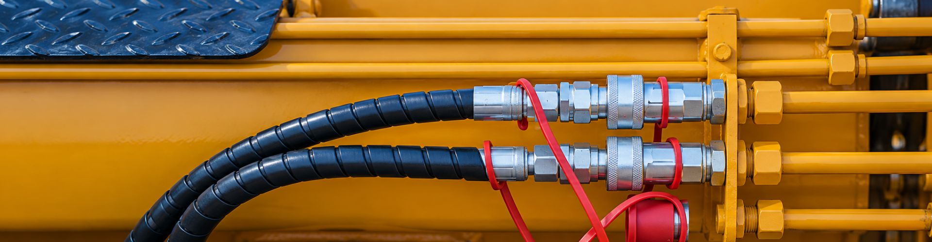
References:


FAQ

What is hydraulic hose crimping volume, and why is it important?

Crimping volume refers to the amount of compression applied to the hose fitting during the installation of a hydraulic hose assembly. It directly affects the seal, strength, and service life of the connection.

How do you determine the correct crimping volume formula?

The correct crimping formula depends on the hose type, working pressure, and operating environment. A commonly used formula is:D = (d₁ – d₂) + [D₀ – (D₂ – D₁)] – E(D₁ – d₂ – A).

What problems can under-crimping or over-crimping cause?

Under-crimping can lead to the fitting loosening or detaching under pressure. Over-crimping may damage the wire reinforcement, cut into the inner tube, or reduce the inner diameter, restricting flow. Both can result in system failure.

How should crimping volume be adjusted for different working environments?

For high-pressure applications, tighter tolerances are required. In low-temperature environments, increase the compression rate by 2–5%. For special fluids, adjustments to the compression rate and fitting materials may be needed. In high-vibration environments, slightly increasing crimping can enhance grip.

How can you verify if the crimping quality is acceptable?

Verify crimp quality through visual inspection (uniformity, no damage), dimensional measurements (multi-point diameter checks), pressure testing (1.5–2× working pressure), and pull tests. A proper crimp should fall within specified tolerances and show no signs of leakage.

What tools are needed for accurate crimping volume calculation?

You’ll need precision measuring tools (such as digital calipers and micrometers) to gather parameters, calculation software or apps for support, and a well-calibrated crimping machine.

Hydraulic Hoses Patching, Binding, Splicing

Hydraulic Hoses Repair Guide: Patching, Binding, Splicing

Hydraulic hoses are the lifelines of countless industrial and mobile equipment systems, transferring power that keeps operations running smoothly. When these critical components fail—whether from age, abrasion, excessive pressure, or environmental damage—every minute of downtime translates to lost productivity and revenue. Understanding emergency repair methods like patching, binding, and splicing isn’t just helpful—it’s essential for minimizing costly interruptions.

Understanding Hydraulic Hose Damage: Diagnosis Before Repair

Before attempting any hydraulic hose repair, proper diagnosis is essential. Like a doctor examining a patient, you need to thoroughly assess the damage to determine the most effective treatment approach.

Visual Inspection Techniques to Identify Damage Types

Start your diagnosis with a methodical visual inspection. Look for these common damage indicators:

hydraulic hose Blistering and Bubbles

Pressure Testing to Locate Hidden Leaks

Not all damage is visible to the naked eye. For suspected leaks that aren’t immediately apparent:

The Anatomy of a Hydraulic Hose and How It Affects Repair Options

Understanding hose construction is crucial for effective repairs:

The depth of damage through these layers directly determines your repair options. Surface-level repairs can address outer cover damage, while reinforcement layer damage requires more robust solutions.

When Repair is Possible vs. When Replacement is Necessary

Make this critical decision based on these factors:

Repair is Generally Possible When:

Replacement is Necessary When:

Essential Tools and Materials for Emergency Hydraulic Hose Repair

When hydraulic hoses fail unexpectedly, having the right tools and materials on hand can mean the difference between a quick fix and costly downtime. A well-prepared emergency repair kit is an investment that pays dividends when pressure is mounting—both in your hydraulic system and on your timeline.

Must-have Items in Your Hydraulic Repair Kit

Every professional hydraulic technician or equipment operator should maintain a comprehensive repair kit containing:

Specialized Adhesives and Their Applications

Different hydraulic repair scenarios require specific adhesive solutions:

hydraulic hose leak holes

Reinforcement Materials for Different Pressure Ratings

The pressure rating of your hydraulic system dictates the appropriate reinforcement materials:

Always remember that reinforcement materials must extend at least 2-3 inches beyond the damaged area in both directions to distribute pressure effectively.

Safety Equipment You Shouldn’t Work Without

Hydraulic systems store tremendous energy, and fluid can be injected into skin at pressures as low as 100 PSI. Never compromise on these safety essentials:

Remember that even the best emergency repair is temporary. Always plan for proper replacement of damaged hoses as soon as feasible, and never exceed the manufacturer’s pressure ratings for your hydraulic system, especially after performing emergency repairs.

The Patching Method: Quick Fixes for Minor Leaks

Small leaks are one of the most common problems in the daily operation of hydraulic systems. The patching method provides a quick and effective solution that allows the equipment to continue operating until a permanent replacement is possible. This method is particularly suitable for addressing pinhole leaks, small cracks, and minor abrasions that haven’t compromised the structural integrity of the hose.

Depressurize and Secure the System

Completely relieve system pressure following manufacturer guidelines

Lock out power sources to prevent accidental pressurization

Place containment materials under the repair area to collect residual fluid

Use a pressure gauge to confirm the system is fully depressurized, a critical safety step

Record the original working pressure of the system for reference during testing

Prepare the Damaged Area

Clean a section extending at least 3 inches beyond the damage in all directions

Use brake cleaner or isopropyl alcohol to remove all hydraulic fluid, dirt, and contaminants

For stubborn oil residue, use professional degreasers such as CRC Brakleen or WD-40 Professional Degreaser

Thoroughly blow dry the area with compressed air, ensuring no solvent remains

Allow the area to dry completely—moisture is the enemy of proper adhesion

Use a UV detection light to confirm no hydraulic oil remains, as even invisible residue will affect bonding

Roughen the Surface

Use 80-120 grit sandpaper to create a slightly rough texture on the hose exterior

For hard outer layer hoses, consider using diamond grit or a small electric sander

The roughened area should be 2-3 inches larger than the actual damaged area, creating a “transition zone”

This mechanical preparation significantly improves adhesive bonding

Wipe away all sanding dust with a clean, lint-free cloth

Avoid touching the prepared surface with fingers, as skin oils reduce adhesion effectiveness

hydraulic hose with Teflon tape

Apply the Primary Sealant

For epoxy putties: Mix according to manufacturer instructions until the color is uniform

Use plastic spatulas or wooden tools for mixing, avoiding contamination from metal tools

Mix small quantities in multiple batches rather than one large batch to prevent failure before curing

Create a “swirl” pattern in the mixture to ensure components are fully incorporated

For liquid sealants: Apply thin, even coat directly over the damaged area

Use a small brush to ensure even coverage

For vertical surfaces, use non-drip formulations or thickening agents

Apply a first thin coat, and allow partial curing (about 5-10 minutes) before applying a second coat

For repair tapes: Begin wrapping with 50% tension and 50% overlap

Start wrapping 2 inches below the damage point

Maintain constant tension, avoiding tape wrinkles or folds

Gently squeeze after completing each layer to expel possible air bubbles

Add Reinforcement Layers

Apply fiberglass mesh or repair fabric over the initial sealant layer

Pre-cut appropriately sized reinforcement materials to avoid adjustments during application

For round hoses, prepare material that can completely wrap the circumference plus 50% overlap

Saturate the reinforcement with additional adhesive or epoxy

Use a roller or brush to ensure complete saturation with no dry areas or air bubbles

For high-pressure applications, consider using multiple layers of reinforcement, fully saturated between layers

Extend reinforcement at least 2 inches beyond the damage in all directions

For systems operating above 2000 PSI, extend at least 3 inches

Ensure reinforcement material edges transition smoothly to avoid stress concentration points

Secure and Cure

Wrap the entire repair with self-amalgamating tape to compress and secure layers

Use at least three layers of self-amalgamating tape with 50% overlap

Start wrapping from one end of the repair area and move evenly to the other end

Follow the manufacturer’s curing time—typically 1-4 hours depending on the product

Environmental temperature affects curing time: below 65°F, curing time may double

High humidity environments also extend curing time, consider using heaters or dehumidifiers

Protect the repair from contamination during curing

Consider using temporary protective covers or barriers

Avoid final curing in dusty or humid environments

For rapid curing needs, a heat gun can carefully accelerate the curing process

Keep the heat gun moving to avoid localized overheating

Follow adhesive manufacturer recommendations regarding maximum temperature

Test Gradually

Begin with low pressure (10-15% of operating pressure)

Use an accurate pressure gauge to monitor test pressure

Maintain this pressure for at least 5 minutes, observing any changes

Inspect for leaks or bulging

Use a magnifying glass to carefully examine the repair area

Gently wipe with a clean white paper towel to check for fluid traces

If the initial test is successful, gradually increase to 50% of operating pressure

Increase pressure in increments of no more than 10%, holding each level for 3-5 minutes

Document observations at each pressure level

Monitor the repair closely during the first few hours of operation

Schedule regular checks: every 15 minutes for the first hour, then hourly for the next 4 hours

Consider installing temporary pressure sensors in the repair area for continuous monitoring

Establish a monitoring log to record repair performance over time

Include date, time, pressure readings, and observations

Take photographs of the repair area for comparison and documentation

Comparison of Hydraulic Repair Materials

Pressure Limitations of Patched Repairs

Understanding the limitations of patched repairs is critical for safe operation.

Pressure Derating

Always reduce the maximum working pressure of a patched hose by at least 25% for safety.

Use the following derating formula for accurate calculation:

Max Safe Pressure After Repair = Original Working Pressure × (1 – Safety Derating Factor)

Safety Derating Factors by Repair Type:

Surface Repair (outer layer only): 0.25 (25% reduction)

Moderate Repair(outer + partial reinforcement): 0.40 (40% reduction)

Deep Repair (near or includes inner layer): 0.60 (60% reduction)

Dynamic vs Static Applications

Patched hoses perform better in static applications. For systems with significant vibration or movement, reduce pressure by an additional 15%.

Vibration Frequency Impact:

Low frequency (<10Hz): additional 10% reduction

Medium frequency (10–50Hz): additional 15% reduction

High frequency (>50Hz): additional 25% reduction

Movement Type Impact:

Axial movement: additional 10% reduction

Bending motion: additional 20% reduction

Torsional movement: additional 30% reduction

Temperature Factors

High temperatures further reduce pressure capacity.

For every 50°F above the rated temperature, reduce pressure by an additional 10%.

Temperature Adjustment Formula:

Temperature Coefficient = 1 – (0.1 × (Current Temp – Rated Temp) ÷ 50)

Cold Start Consideration:

At temperatures below 32°F, limit system pressure to 30% of the normal working pressure until fluid temperature rises.

Temperature Cycling:

Frequent temperature fluctuations accelerate repair degradation. If there are more than 3 full temperature cycles per day, reduce pressure by an additional 5%.

Binding Techniques: Reinforcing Damaged Sections

When Binding Is Your Best Emergency Option

In emergency maintenance scenarios—particularly in remote locations or when replacement parts are delayed—binding becomes an essential first-response technique to prevent fluid loss and pressure drops. While not a permanent repair method, it can provide crucial temporary reinforcement and restore operational capability for limited durations.

Binding is most effective in:

However, even with ideal execution, binding repairs should be closely monitored and marked for replacement at the earliest opportunity.

Binding Materials for Emergency Hydraulic Hose Repairs

The Wire-Wrap Method for High-Pressure Applications

For high-pressure or structurally compromised hose sections, the wire-wrap method offers the strongest field-appropriate reinforcement. When done correctly, it mimics the hoop-strength behavior of internal braid reinforcement.

Step-by-Step Procedure:

Clean and dry the hose thoroughly—remove all hydraulic fluid residue, dirt, and oxidation.

Apply a Base Sealant Layer using high-strength epoxy putty or self-fusing rubber tape.

Anchor the First Wrap at least 1–2 inches below the damaged section.

Spiral Wrap Upward using stainless wire, maintaining uniform tension (avoid slack or kinks).

Overlap Each Layer by 50%, ensuring there are no gaps in coverage.

Wrap Beyond Damage Zone: Extend 1–2 inches above the damaged area for full containment.

Double Back Downward for added strength and compression.

Secure Wire Ends with clamps, tie-off knots, or additional epoxy sealing.

Cure (if epoxy used), and allow cooling to ambient temperature before re-pressurizing.

Splicing Methods: Reconnecting Completely Severed Hoses

When a hydraulic hose is completely severed, splicing provides a field-repair solution to reconnect both ends—restoring system integrity until full replacement is possible. While not always suitable for high-frequency or dynamic systems, proper splicing with rated components can restore pressure containment and fluid flow in static or moderate-duty lines.

Cutting and Preparation Techniques for Clean Splices

A clean and precise cut is critical for achieving a leak-free, pressure-rated connection. Poor preparation is the number one cause of splice failure.

Preparation Steps:

Depressurize the system fully before handling the hose.

Cut square using a hose saw or a fine-toothed blade—ensure edges are flat, not frayed.

Clean internal bore and external cover using solvent wipes to remove hydraulic fluid and debris.

Deburr if needed using abrasive cloth or file—especially with steel-reinforced hoses.

Mark insertion depth for each fitting to ensure full engagement.

Connector Types and Their Pressure Ratings

Choosing the correct connector is essential to match the hose size, pressure rating, and application type.

Step-by-Step Splicing Procedure

Prepare Both Hose Ends as described above.

Insert Connectors Fully to the marked depth—apply light lubricant (if specified).

Tighten Compression or Clamp Fittings per torque spec. For reusable fittings, thread ferrule first, then insert nipple.

Secure and Align hoses to prevent twisting.

Re-pressurize slowly while inspecting for leaks.

Perform Function Test under full operating pressure before returning to service.

Common Mistakes to Avoid When Splicing Hydraulic Lines

Best Practices Summary

Always use pressure-rated, field-repairable connectors.

Maintain a mobile hose repair kit with common fittings.

Log all spliced sections with location, date, and pressure rating.

Replace spliced hoses at the next scheduled downtime.

Conclusion

A proactive emergency response plan can make the difference between a quick recovery and costly downtime. While temporary fixes like patching, binding, or splicing can restore function in the short term, they should never replace a proper hose replacement. Once the immediate issue is under control, it’s critical to replace the damaged hose with a new, pressure-rated hydraulic hose to ensure long-term safety and system reliability.

Contact us now to get expert recommendations or place your order today!


FAQ

Can a hydraulic hose be permanently repaired?

No. All field repairs such as patching or binding are temporary. A full hose replacement is always recommended for long-term safety and reliability.

What is the maximum pressure a patched hydraulic hose can handle?

It depends on the repair method, but generally, you should reduce the original working pressure by at least 25% after patching.

How long can I use a spliced or patched hydraulic hose?

Most temporary repairs are safe for 24–48 operating hours or up to 3 weeks in low-pressure static applications. Regular monitoring is required.

What tools do I need for emergency hose binding?

Basic tools include stainless steel wire, epoxy putty, wire tensioner, rubber padding, and cleaning materials. A repair kit is strongly recommended.

Can I use zip ties for hydraulic hose repair?

Only in very low-pressure, non-critical applications. Zip ties are not rated for pressure sealing and should be used cautiously as a last resort.

Is it safe to use repaired hoses in high-temperature environments?

Only temporarily. Temperature extremes reduce repair reliability. Always consider derating pressure and plan for prompt hose replacement.

Contact Topa

Save 30% on maintenance costs with our easy-install hydraulic fittings. Contact Now!