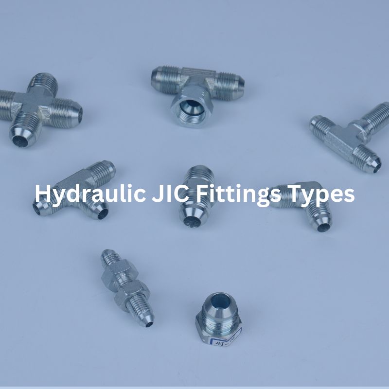
JIC Fitting Specifications What You Need to Know

JIC Fitting Specifications: What You Need to Know

JIC Fitting Specifications: What You Need to Know

Table of Contents

Introduction

Understanding JIC fitting specifications is crucial for anyone involved in the hydraulic systems industry. JIC fittings are essential components that ensure the efficiency and safety of hydraulic systems, widely used across various sectors. This post aims to provide a comprehensive guide on JIC fitting specifications, helping you make informed decisions for your applications.

What are JIC Fittings?

JIC fittings are a specific type of hydraulic fitting designed with a 37-degree flare seating surface. This unique angle is engineered to create a metal-to-metal seal, which is essential for maintaining a secure and leak-free connection, particularly in high-pressure applications. The design of JIC fittings makes them highly reliable and effective in preventing leaks, which is crucial in systems that handle high-pressure fluids. This metal-to-metal contact ensures a tight seal without the need for additional sealants, which simplifies maintenance and enhances reliability.

History and Development

The development of JIC fittings dates back to World War II. During this period, the need for standardized hydraulic connections in military equipment became apparent. The military required robust and reliable fittings that could be easily manufactured and consistently meet stringent performance standards. As a result, the Joint Industry Council was formed to create a standardized fitting that could be used across various military applications. The 37-degree flare design was chosen for its superior sealing capabilities and ease of production. Following the war, the effectiveness and reliability of JIC fittings led to their adoption in civilian industries.

Common Applications

The versatility and reliability of JIC fittings have made them a staple in many industries.

Agriculture: In the agricultural sector, JIC fittings are commonly used in hydraulic systems for tractors, harvesters, and other farm equipment.

Construction: Heavy machinery such as excavators, bulldozers, and cranes rely on hydraulic systems that incorporate JIC fittings.

Transportation: The transportation industry uses JIC fittings in the hydraulic systems of trucks, buses, and other vehicles.

Fluid Power Systems: JIC fittings are integral to fluid power systems, where they connect different components such as pumps, valves, and actuators.

Fuel Delivery Systems: In fuel delivery systems, JIC fittings ensure that fuel is transported efficiently and without leaks.

Key Specifications of JIC Fittings

Size Specifications: JIC fittings are designed to accommodate a wide range of sizes, ensuring compatibility with various hydraulic systems. The sizes are typically denoted in dash numbers (e.g., -4, -6, -8), which correspond to the fitting’s outside diameter (OD) measured in sixteenths of an inch. This standardized sizing system allows for easy identification and interchangeability. For instance, a -4 JIC fitting has an OD of 1/4 inch, a -6 fitting has an OD of 3/8 inch, and so on. This sizing convention helps streamline the selection process, ensuring that the correct fitting size is chosen for each application. Additionally, the use of dash numbers simplifies inventory management and reduces the risk of using incompatible fittings.

Pressure Ratings

The pressure rating of JIC fittings is a critical specification that varies depending on the size and material of the fitting.

Smaller Sizes: For smaller JIC fittings, such as those with dash numbers -4 or -6, the pressure ratings can be as high as 10,000 psi. These high-pressure ratings make them suitable for demanding applications in hydraulic systems that operate under extreme conditions.

Larger Sizes: Larger JIC fittings, such as those with dash numbers -12 or -16, typically have lower pressure ratings, around 6,000 psi. While still robust, these fittings are designed for applications where lower pressure thresholds are acceptable.

Temperature Ratings

JIC fittings are engineered to operate effectively across a broad temperature range, which is crucial for maintaining the integrity and performance of hydraulic systems in various environments.

General Range: Typically, JIC fittings can function in temperatures ranging from -65°F to 400°F (-54°C to 204°C). This wide range accommodates both extremely cold and hot conditions, ensuring the fittings remain reliable under diverse operating scenarios.

Material-Specific Tolerances: The material of the JIC fitting significantly influences its temperature tolerance.

Stainless Steel: Stainless steel JIC fittings have the highest temperature tolerance, making them suitable for applications that experience extreme temperature fluctuations or high-temperature conditions.

Carbon Steel and Brass: While still effective, carbon steel and brass fittings generally have lower temperature tolerances compared to stainless steel. These materials are more suitable for applications where the temperatures are within moderate ranges.

Standards and Certifications

Industry Standards

JIC fittings are designed and manufactured to adhere to strict industry standards to ensure quality, safety, and compatibility. One of the primary standards for JIC fittings is the SAE J514, which outlines the design, dimensions, and performance requirements for 37-degree flare fittings. Additionally, this standard covers the technical aspects of JIC fittings, such as material specifications, dimensional tolerances, and performance benchmarks, ensuring that all fittings meet a consistent level of quality and reliability.

Certifications

To further guarantee quality and performance, many JIC fittings are certified by internationally recognized organizations. Two of the most notable certifying bodies are the ISO (International Organization for Standardization) and ASTM (American Society for Testing and Materials).

ISO Certifications: ISO certification indicates that the JIC fittings meet international standards for quality management and environmental management systems. ISO standards, such as ISO 9001, ensure that the manufacturing processes for JIC fittings are optimized for quality control, consistency, and continuous improvement. This certification assures customers that the fittings are produced under stringent quality management systems.

ASTM Certifications: ASTM certification, such as ASTM B633, which pertains to electrodeposited coatings of zinc on iron and steel, signifies that the fittings meet specific material and performance criteria. ASTM standards ensure that the materials used in the production of JIC fittings have been rigorously tested and meet the required specifications for durability, corrosion resistance, and mechanical properties.

JIC thread hydraulic Fitting Topa

Compliance and Testing

To meet the high standards set by organizations like SAE, ISO, and ASTM, JIC fittings undergo extensive testing during and after the manufacturing process. These tests are designed to ensure that the fittings can perform reliably in various demanding applications and environments.

Pressure Tests: Pressure testing is conducted to verify that the JIC fittings can withstand the maximum specified operating pressures without failure or leakage. This involves subjecting the fittings to pressures higher than their rated capacity to ensure they have an adequate safety margin.

Temperature Cycling Tests: Temperature cycling tests expose the fittings to extreme temperatures, both hot and cold, to evaluate their performance and durability under thermal stress. This testing ensures that the fittings can maintain their integrity and sealing capabilities across a wide temperature range.

Vibration Tests: Vibration testing simulates the conditions that fittings may encounter in applications with high levels of mechanical vibration. These tests assess the fittings’ ability to maintain a secure connection without loosening or leaking under continuous vibration.

In addition to these specific tests, JIC fittings may also undergo other types of evaluations, such as corrosion resistance tests, tensile strength tests, and fatigue tests. These comprehensive testing protocols ensure that the fittings meet or exceed industry standards, providing users with confidence in their performance and reliability.

How to Identify JIC Fittings

Identification Marks

One of the easiest ways to identify JIC fittings is through the identification marks that manufacturers often imprint on the fittings. These marks usually include critical information such as the size, material, and manufacturer. For example, a fitting might be marked with “JIC-08-SS” indicating a JIC fitting, size 8 (which corresponds to 1/2 inch), made of stainless steel. These markings help ensure that the correct fitting is used for specific applications, especially in environments where multiple types of fittings might be present.

Visual Identification: Another method to identify JIC fittings is through visual inspection. The most distinctive feature of a JIC fitting is the 37-degree flare angle, which can be seen at the end of the fitting where the connection is made. This flare creates a metal-to-metal seal, which is crucial for the fitting’s performance in high-pressure applications. Additionally, JIC fittings often have a hexagonal body, allowing for easy installation and removal using standard wrenches.

Measurement Techniques

Accurate measurement is essential for identifying the correct size of JIC fittings, ensuring they fit properly and function correctly in hydraulic systems. The primary tools used for this purpose are calipers and thread pitch gauges.

Calipers: Calipers are used to measure the outside diameter (OD) of the fitting. To do this, place the caliper’s jaws around the fitting’s outer edge and read the measurement on the caliper’s scale. This measurement, typically given in inches or millimeters, will correspond to the dash number size of the fitting.

Thread Pitch Gauges: To measure the thread size accurately, a thread pitch gauge is used. This tool has multiple blades, each with a different thread pitch. To use it, match the fitting’s threads to the corresponding blade on the gauge until you find an exact fit. The thread pitch gauge will tell you the threads per inch (TPI) or the metric thread pitch, which helps verify the fitting’s thread specifications.

By using these measurement techniques, you can ensure that the correct JIC fitting is selected and installed. This process is critical for maintaining the integrity and reliability of hydraulic systems, preventing issues such as leaks, misalignment, or thread damage.

Installation and Maintenance

Proper installation of JIC fittings is essential for ensuring a secure and leak-free connection in hydraulic systems. Here’s a step-by-step guide:

Cleaning the Mating Surfaces: Before installation, thoroughly clean the mating surfaces of both the fitting and the connection point. Use a clean cloth and an appropriate solvent to remove any dirt, debris, or oils. This step is crucial to prevent contaminants from compromising the seal.

Aligning the Fitting Correctly: Ensure that the fitting and the mating part are properly aligned. Misalignment can cause undue stress on the connection, leading to leaks or fitting failure. Carefully hand-thread the fitting to check for smooth engagement before applying any torque.

Tightening to the Recommended Torque: Use a calibrated torque wrench to tighten the fitting to the manufacturer’s recommended torque specifications. Over-tightening can damage the threads or the flare, leading to leaks or fitting failure. Under-tightening can result in a weak seal, also causing leaks. Always refer to the torque specifications provided by the fitting manufacturer to ensure proper installation.

Inspection After Installation: Once installed, inspect the connection to ensure there are no visible gaps or misalignments. Check the fitting for any signs of stress or deformation, which could indicate improper installation.

Common Installation Mistakes

Avoiding common installation mistakes can significantly enhance the reliability and longevity of JIC fittings. Here are some pitfalls to watch out for:

Using the Wrong Size Fitting: Ensure you select the correct size fitting for the application. Using an incorrect size can result in poor sealing and connection issues.

Not Cleaning the Mating Surfaces: Installing fittings on dirty or contaminated surfaces can lead to leaks and compromised connections. Always clean the mating surfaces before installation.

Improper Tightening: Over-tightening can damage the fitting and the mating component, while under-tightening can lead to inadequate sealing. Use a torque wrench to apply the correct amount of torque.

Skipping Visual Inspection: Failing to visually inspect the fitting after installation can result in missed alignment issues or other problems that could compromise the connection.

Troubleshooting

Addressing common issues with JIC fittings promptly can prevent minor problems from escalating into major failures. Here are some troubleshooting tips:

Leaks: If a fitting is leaking, first check if it has been properly tightened to the recommended torque. If tightening does not resolve the leak, inspect the flare and threads for damage. Replace any damaged fittings.

Thread Damage: Damaged threads can compromise the integrity of the connection. Inspect the threads for signs of wear or cross-threading. Replace fittings with damaged threads to ensure a secure connection.

Excessive Wear: Regularly check the fittings for signs of excessive wear, which can weaken the connection and lead to leaks. Replace worn fittings promptly.

Contamination: Contaminants can cause premature wear and damage to fittings. Ensure that all components are clean during installation and maintenance. Use filters and regular fluid changes to minimize contamination.

Comparing JIC Fittings with Other Types

37 vs 45 degree

JIC vs SAE Fittings

While both JIC and SAE fittings are commonly used in hydraulic systems, they have key differences that affect their compatibility and performance in specific applications.

Flare Angle: The primary difference between JIC and SAE fittings lies in the flare angle. JIC fittings have a 37-degree flare angle, whereas SAE fittings have a 45-degree flare angle. This difference means that the two types of fittings are not interchangeable and are designed for different sealing mechanisms.

Compatibility: Because of the different flare angles, JIC and SAE fittings are not compatible with each other. Attempting to use them interchangeably can lead to poor seals, leaks, and potential system failures.

JIC vs NPT Fittings

JIC and NPT fittings have different sealing mechanisms, which influence their use and performance in hydraulic systems.

Sealing Mechanism: NPT (National Pipe Tapered) fittings rely on a tapered thread to create a seal. As the fitting is tightened, the taper compresses, creating a seal. However, this type of seal can be prone to leaks if not installed correctly and often requires the use of thread sealant or Teflon tape to ensure a tight seal.

Metal-to-Metal Seal: JIC fittings, on the other hand, provide a more reliable metal-to-metal seal through the 37-degree flare angle. This design reduces the risk of leaks, especially in high-pressure applications, by ensuring a tight and secure connection without the need for additional sealants.

JIC vs ORFS Fittings

ORFS (O-ring Face Seal) fittings and JIC fittings both offer reliable sealing solutions but are suited to different types of applications.

Sealing Mechanism: ORFS fittings use an O-ring to create a seal. The O-ring sits in a groove on the face of the fitting, and when the fitting is tightened, the O-ring is compressed against a flat face on the mating part, creating a seal. This design offers superior leak resistance, especially in high-vibration and high-pressure applications.

Leak Resistance: The O-ring in ORFS fittings provides a more robust seal compared to the metal-to-metal seal of JIC fittings. This makes ORFS fittings particularly suitable for applications where leak prevention is critical, such as in hydraulic systems subject to high-pressure spikes or constant vibration.

Conclusion

In summary, understanding JIC fitting specifications is essential for ensuring the efficiency, safety, and reliability of hydraulic systems. By familiarizing yourself with the key specifications, standards, and installation practices, you can make informed decisions and optimize your hydraulic applications. For further assistance or specific questions, feel free to reach out to Topa experts or manufacturers.

FAQ

JIC stands for Joint Industry Council, which standardized these fittings during World War II to ensure consistent, reliable hydraulic connections.

JIC fittings have a 37-degree flare angle, which creates a metal-to-metal seal for high-pressure applications.

No, JIC fittings cannot be used interchangeably with SAE fittings because SAE fittings have a 45-degree flare angle, making them incompatible.

Measure the outside diameter (OD) of the fitting and the thread pitch using calipers and a thread pitch gauge. The size is typically denoted in dash numbers representing sixteenths of an inch.

JIC fittings are commonly made from carbon steel, stainless steel, and brass. The choice of material depends on the application requirements, such as pressure, temperature, and corrosion resistance.

JIC fittings are used in various industries, including agriculture, construction, manufacturing, and transportation, for applications requiring durable, high-pressure hydraulic connections.

37 Degree Flare vs 45 Degree Flare Key Differences

37 Degree Flare vs 45 Degree Flare: Key Differences

37 Degree Flare vs 45 Degree Flare: Key Differences

Table of Contents

Introduction

Flared fittings play a crucial role in hydraulic and plumbing systems, ensuring secure and leak-free connections. Among these, 37-degree and 45-degree flare fittings are the most commonly used. This article explores the key differences between these two types, providing insights to help you select the right fitting for your applications.

Understanding Flared Fittings

Flared fittings achieve this by flaring the tube end and securing it with a corresponding flare fitting. This method creates a strong, reliable joint, ideal for high-pressure scenarios. The concept of flaring involves expanding the tube end to a specific angle, allowing it to mate perfectly with the flare fitting, creating a metal-to-metal seal. Over the years, these fittings have advanced to meet the stringent demands of various industries, including automotive, aerospace, and heavy machinery.

The Flare Fitting Process

The flaring process starts by cutting the tube to the required length and ensuring the end is smooth and free from burrs. The tube end is then expanded using a flaring tool to create the flare, which matches the angle of the fitting. The fitting is then tightened, creating a seal that is both robust and flexible, accommodating the natural movements and vibrations of the system without compromising the connection.

Advantages of Flared Fittings

Pressure Resistance: Flared fittings can handle high-pressure applications, making them ideal for hydraulic systems.

Durability: The metal-to-metal seal ensures a long-lasting connection that can withstand harsh conditions.

Versatility: They are compatible with various tube materials, including steel, stainless steel, copper, and aluminum, catering to diverse industry needs.

Detailed Overview of 37 Degree Flare Fittings

JIC 74° Topa

37-degree flare fittings, also known as JIC (Joint Industry Council) fittings, are integral to hydraulic systems, offering robust and reliable connections. The distinguishing feature of these fittings is the 37-degree angle flare that matches the tube’s flared end, providing a secure and leak-resistant joint.

Design and Construction

Materials: Typically made from stainless steel, brass, or carbon steel, ensuring durability and resistance to corrosion.

Mechanical Grip and Seal: The 37-degree angle creates a strong mechanical grip and an excellent metal-to-metal seal, essential for high-pressure applications.

Advantages

High Pressure Tolerance: These fittings can withstand pressures up to 10,000 PSI, making them suitable for demanding hydraulic systems.

Sealing Capabilities: The design minimizes the risk of leaks, ensuring reliability in critical applications.

Versatility: Suitable for a wide range of applications across various industries, including automotive, aerospace, and heavy machinery.

Limitations

Cost: 37-degree flare fittings are generally more expensive compared to some other types of fittings due to their robust design and material quality.

Compatibility: These fittings are not interchangeable with systems designed for 45-degree flare fittings, which may limit their use in certain applications.

Detailed Overview of 45 Degree Flare Fittings

45-degree flare fittings are essential components in plumbing, refrigeration, and certain automotive applications. Designed with a 45-degree flare, these fittings connect soft tubing materials, providing secure and reliable joints for lower pressure systems.

Design and Construction

Angle: The defining characteristic is the 45-degree flare angle, creating a seal by flaring the tube end to match the fitting.

Materials: Commonly made from brass and copper, chosen for their corrosion resistance and ease of installation.

Construction: These fittings feature a conical surface, which, when tightened, compresses the flared tube end against the fitting to form a tight seal.

Advantages

Versatility: 45-degree flare fittings are used in various applications, including plumbing, HVAC systems, and certain automotive contexts. They are particularly effective in systems where the pressure is lower, and flexibility is needed.

Cost-Effectiveness: Generally more affordable than 37-degree flare fittings, making them a cost-effective solution for many standard applications. Their widespread availability ensures they are easy to source and replace.

Limitations

Pressure Tolerance: These fittings typically handle lower pressures compared to 37-degree flare fittings, making them unsuitable for high-pressure hydraulic systems. They are generally rated for pressures up to 2,000 PSI, significantly lower than the 10,000 PSI tolerance of 37-degree fittings.

Potential for Leakage: In high-stress applications, 45-degree flare fittings may be more prone to leakage. The seal created by the 45-degree flare is less robust under extreme pressure or when subjected to significant vibrations and movements.

Key Differences Between 37 vs 45 Degree Flare Fittings

Comparative Analysis of Design and Construction

Design:

37-Degree Flare Fittings: These fittings feature a 37-degree flare angle, known as JIC (Joint Industry Council) fittings. The design allows for a tight metal-to-metal seal, ensuring a robust connection. Typically used in high-pressure systems, these fittings are constructed from materials like stainless steel, brass, and carbon steel, providing durability and resistance to corrosion.

45-Degree Flare Fittings: These fittings have a 45-degree flare angle and are commonly used in plumbing and HVAC systems. Constructed primarily from brass and copper, they are designed for use with softer tubing materials. The 45-degree angle provides adequate sealing for lower pressure applications but is not as robust as the 37-degree design.

Construction:

Materials: 37-degree fittings are usually made from stronger materials like stainless steel and carbon steel to handle high pressures. In contrast, 45-degree fittings are often made from brass or copper, suitable for lower pressure systems.

Mechanics: The 37-degree flare fitting offers a more substantial mechanical grip due to the steeper angle, which can withstand higher stresses. The 45-degree fitting, with its shallower angle, is easier to install but not as strong under high-pressure conditions.

Performance Under Pressure: 37 vs 45 Degrees

37 vs 45 degree

37-Degree Flare Fittings:

High Pressure Tolerance: Capable of handling pressures up to 10,000 PSI, making them ideal for high-pressure hydraulic systems.

Durability: The robust construction and stronger materials ensure longevity and reliability under extreme conditions.

Sealing Capability: Excellent sealing properties reduce the risk of leaks, even under high pressure.

45-Degree Flare Fittings:

Lower Pressure Tolerance: Generally suitable for pressures up to 2,000 PSI, these fittings are ideal for lower pressure applications such as plumbing and HVAC systems.

Performance in High-Stress Conditions: More prone to leakage and failure when subjected to high pressures and vibrations, limiting their use in more demanding environments.

Installation Process and Ease of Use

37-Degree Flare Fittings:

Installation: Requires precise flaring tools and techniques to ensure a proper seal. The higher pressure applications demand meticulous installation to avoid leaks and failures.

Ease of Use: While installation can be more complex, the robust design ensures a secure and reliable connection once properly installed.

45-Degree Flare Fittings:

Installation: Easier and quicker to install compared to 37-degree fittings. The use of softer materials like copper and brass simplifies the flaring process.

Ease of Use: More user-friendly for installers, particularly in applications where high precision is not as critical. Ideal for DIY projects and standard plumbing tasks.

Choosing the Right Flare Fitting for Your Needs

Selecting between 37-degree and 45-degree flare fittings requires careful consideration of several factors to ensure optimal performance and reliability in your fluid system. Here’s a detailed guide to help you make the right choice:

Pressure Requirements

37-Degree Fittings: Ideal for high-pressure systems, these fittings can withstand pressures up to 10,000 PSI. They are suitable for hydraulic systems, military applications, and other demanding environments.

45-Degree Fittings: Suitable for lower pressure applications, typically up to 2,000 PSI. These are commonly used in plumbing, HVAC systems, and some automotive applications where high pressure is not a concern.

Fluid or Gas Type

Compatibility: Ensure the fitting material is compatible with the fluid or gas being transported. For instance, stainless steel is excellent for corrosive fluids, while brass is suitable for non-corrosive applications.

Seal Integrity: Different fluids may require specific sealing capabilities. High-pressure hydraulic fluids need the robust sealing of 37-degree fittings, whereas refrigerants in HVAC systems can use 45-degree fittings.

Environmental Conditions

Temperature: Consider the operating temperature range of the system. High-temperature environments may require materials that can withstand thermal expansion and contraction without compromising the seal.

Corrosive Elements: Exposure to corrosive elements necessitates fittings made from corrosion-resistant materials like stainless steel or brass. The environmental conditions will dictate the longevity and maintenance needs of the fittings.

Budget

Initial Cost: 45-degree fittings are generally more affordable than 37-degree fittings due to their construction and material costs. This makes them a cost-effective choice for standard applications.

Long-Term Performance: While 37-degree fittings may have a higher initial cost, their durability, and high-pressure capabilities can lead to lower maintenance costs and longer service life, providing better value over time.

Compatibility

System Components: Ensure the selected fittings match the existing system components. Incompatibility can lead to leaks, reduced efficiency, and potential system failures.

Interchangeability: Note that 37-degree and 45-degree fittings are not interchangeable. Using the wrong type can result in improper sealing and connection issues.

Decision-Making Framework

Assess Your System’s Pressure Requirements: Identify the maximum operating pressure and choose a fitting type that can safely handle it.

Determine Fluid or Gas Compatibility: Match the fitting material to the type of fluid or gas being transported to ensure compatibility and safety.

Evaluate Environmental Factors: Consider the temperature and potential corrosive elements in the operating environment to select a fitting material that will perform reliably.

Balance Budget and Performance: Weigh the initial cost against long-term performance and maintenance needs to choose the most cost-effective solution.

Verify Compatibility with Existing Components: Ensure the fittings match the current system components to avoid any compatibility issues.

Common Mistakes to Avoid

Mismatching Fittings: Using 37-degree fittings in systems designed for 45-degree fittings (and vice versa) can lead to improper sealing and leaks.

Underestimating Pressure Needs: Selecting fittings with a lower pressure tolerance than required can cause system failures and safety hazards.

Ignoring Environmental Conditions: Failing to consider the operating environment can lead to premature fitting failure due to corrosion or thermal stress.

Choose Topa As Your Manufacturer

When selecting a manufacturer for hydraulic fittings, choosing the right partner is crucial. Topa, a leading hydraulic fittings manufacturer based in China, offers exceptional quality, customization, and service. Here’s why Topa stands out and should be your preferred choice.

Unmatched Quality and Reliability

High-Quality Materials: Topa uses top-grade materials, ensuring durability and performance.

Advanced Manufacturing Processes: State-of-the-art technology and stringent quality control measures guarantee superior products.

Proven Track Record: Consistent delivery of reliable flare hydraulic fittings that meet industry standards.

Customization and Flexibility

Tailored Solutions: Topa offers customized hydraulic fittings to meet specific client requirements, providing solutions that fit unique applications.

Wide Range of Products: From standard to specialized hydraulic fittings, Topa’s extensive inventory ensures they can cater to various needs.

Exceptional Service

Hydraulic fitting CNC machine Topa

Professional Team: With a skilled team of 50 professionals, Topa provides expert support and guidance throughout the purchasing process.

One-Stop Service: Topa offers comprehensive services, from design to delivery, ensuring a seamless experience for clients.

Competitive Advantage

Prompt Delivery: Extensive stock allows for quick turnaround times, meeting tight deadlines, and reducing downtime.

Industry Expertise: Topa’s deep understanding of the hydraulic fittings industry ensures they can address and resolve any client pain points effectively.

Global Reach and Trusted Partnerships

International Clientele: Serving clients in the United States, Europe, Asia, Australia, Germany, and the United Kingdom, Topa has built a reputation for reliability and quality worldwide.

Long-Term Relationships: Focus on building lasting relationships with distributors, retailers, maintenance providers, exporters, and production companies.

Choosing Topa as your hydraulic fittings manufacturer means partnering with a company committed to excellence, quality, and client satisfaction. Their expertise, customization capabilities, and exceptional service make them the ideal choice for all your hydraulic flare fittings needs. Trust Topa to deliver the high-quality solutions your business requires, ensuring smooth and efficient operations.

Conclusion

Choosing between 37-degree and 45-degree flare fittings depends on your specific needs and application requirements. Understanding the key differences, such as pressure tolerance, compatibility, and cost, is crucial for making an informed decision. At Topa, we provide high-quality hydraulic cylinders and fittings tailored to meet your specific requirements. Our extensive range of products, exceptional service, and industry expertise make us the ideal choice for your hydraulic needs. Visit our website or reach out to our professional team to place your order now.

FAQ

37-degree flare fittings, also known as JIC fittings, are designed for high-pressure applications up to 10,000 PSI. 45-degree flare fittings are used in lower pressure systems, typically up to 2,000 PSI, such as plumbing and HVAC systems.

For high-pressure hydraulic systems, 37-degree flare fittings are recommended due to their higher pressure tolerance and robust sealing capabilities.

No, they are not interchangeable. Using the incorrect flare fitting can lead to improper sealing, leaks, and potential system failures.

37-degree flare fittings are typically made from stainless steel, brass, or carbon steel. 45-degree flare fittings are usually made from brass or copper.

Yes, 45-degree flare fittings can be used in automotive applications, especially in fuel and coolant lines, provided the pressure requirements do not exceed the fitting’s capabilities.

Ensure the fitting material matches the fluid or gas being transported and that the fittings are designed for the specific pressure requirements and environmental conditions of your system.

Will JIC Fittings Work with AN Fittings

Will JIC Fittings Work with AN Fittings?

Will JIC Fittings Work with AN Fittings?

Introduction

JIC (Joint Industry Council) and AN (Army-Navy) fittings are both popular in various industries due to their reliable performance in high-pressure and high-vibration environments. Understanding their compatibility is crucial for ensuring optimal performance and safety in hydraulic systems. This post explores whether JIC fittings can be used with AN fittings, highlighting their differences and similarities, and providing practical guidelines for their use.

Will JIC Fittings Work with AN Fittings?

JIC and AN fittings have similar 37-degree flares, allowing them to physically connect. However, due to different thread tolerances and standards, they are not ideally interchangeable. Using JIC fittings in place of AN fittings can lead to leaks and equipment failure while using AN fittings instead of JIC might be unnecessarily costly. The choice depends on the application’s requirements, with AN fittings preferred for high-precision, high-vibration environments and JIC fittings suitable for general hydraulic systems.

Understanding JIC and AN Fittings

What Are JIC Fittings?

JIC hydraulic fittings are a type of flare fitting standardized under SAE J514. These fittings are known for their 37-degree flare seating surface, which creates a tight and leak-proof seal when connected. Commonly used in hydraulic applications, JIC fittings are prized for their robustness, ease of assembly, and adaptability across a range of industries such as automotive, aerospace, and industrial machinery.

JIC fittings come in various materials, including carbon steel, stainless steel, and brass, each chosen based on the specific requirements of the application. Their versatility and durability make them a preferred choice in environments where reliability and performance are critical.

What Are AN Fittings?

AN fittings were originally developed for military use and adhere to the stringent standards set by military specification MS33656. Like JIC fittings, AN fittings feature a 37-degree flare but are manufactured to much tighter tolerances. This precision ensures a secure fit and reliable performance in high-pressure and high-vibration applications. AN fittings are commonly used in aviation, aerospace, and high-performance automotive sectors, where exacting standards are a necessity.

The materials used for AN fittings typically include high-grade aluminum alloys and stainless steel, providing excellent strength and corrosion resistance. The rigorous manufacturing process ensures that AN fittings can handle extreme conditions, offering long-term reliability and safety. These fittings are designed to meet the highest standards of performance, making them indispensable in critical applications where failure is not an option.

Historical Background

The development of JIC and AN fittings can be traced back to different needs and standards. JIC fittings emerged from the industrial sector’s need for a standardized hydraulic connection that could be universally applied across various equipment and machinery. Over time, JIC fittings became a standard in industries requiring robust and reliable hydraulic connections.

AN fittings, on the other hand, were developed to meet the exacting demands of military and aerospace applications. The military required fittings that could withstand extreme conditions, including high pressure, vibration, and varying temperatures. The AN fitting was designed to provide a superior level of precision and reliability, meeting stringent military specifications.

As industries evolved, both JIC and AN fittings were adapted to meet specific needs, resulting in distinct differences in their specifications and uses. While JIC fittings offer versatility and ease of use for general applications, AN fittings provide unmatched precision and reliability for high-stakes environments.

Technical Specifications and Differences

Thread Tolerances and Standards

JIC fittings are manufactured in accordance with SAE standards, which allow for slight variations in thread tolerances. This flexibility is sufficient for many industrial applications but can lead to minor deviations in thread alignment. On the other hand, AN fittings adhere to stringent military specifications, resulting in highly precise and uniform threading. This level of precision is essential in applications where even the smallest deviations can lead to performance issues, such as in aviation or high-performance automotive systems. The tighter tolerances of AN fittings ensure a more secure and reliable connection, minimizing the risk of leaks and mechanical failures.

Material and Build Quality

JIC fittings are typically made from a range of materials, including carbon steel, stainless steel, and brass. The choice of material depends on the specific application and the environmental conditions the fitting will encounter. Carbon steel is commonly used for its strength and affordability, stainless steel for its corrosion resistance and durability, and brass for its excellent machinability and resistance to corrosion.

In contrast, AN fittings are often made from high-grade aluminum alloys or stainless steel. Aluminum alloys are favored in applications where weight reduction is crucial, such as in aerospace and racing, while stainless steel is used for its exceptional strength and resistance to extreme conditions. The high-quality materials and precise manufacturing processes used for AN fittings ensure they can withstand the rigorous demands of high-performance environments, providing long-lasting reliability and safety.

Pressure Ratings and Temperature Limits

An and JIC Fittings

The pressure ratings and temperature limits of JIC and AN fittings differ significantly due to their intended applications and manufacturing standards. JIC fittings generally have lower pressure ratings, making them suitable for less demanding applications. They are designed to handle a range of pressures, but their ratings typically do not match the higher thresholds required for critical applications.

AN fittings are engineered to endure higher pressures and temperatures, making them ideal for use in high-stakes environments where failure is not an option. The stringent manufacturing standards and superior material quality of AN fittings allow them to perform reliably under extreme conditions, ensuring the integrity of the hydraulic or fluid transfer systems they are used in.

Design and Shape Variations

While both JIC and AN fittings feature a 37-degree flare, the design and shape of AN fittings are often more refined. AN fittings typically have smoother surfaces and more precise angles, which contribute to their enhanced performance and reliability. These subtle design differences result from the tighter manufacturing tolerances and higher standards to which AN fittings are held. The refined design of AN fittings ensures a more secure and leak-proof connection, even in the most demanding applications.

In contrast, JIC fittings, while still effective, may have slightly less precise dimensions due to the broader manufacturing tolerances allowed by SAE standards. These differences, though minor, can impact the overall performance and reliability of the fittings in specific applications. Therefore, understanding the design and shape variations between JIC and AN fittings is crucial for selecting the appropriate fitting for the intended use, ensuring optimal performance and safety.

Compatibility and Interchangeability

Physical Compatibility

JIC and AN fittings can physically connect due to their identical 37-degree flare. However, the differences in thread tolerances mean that the fit might not be perfect, potentially leading to issues like leaks. It’s essential to ensure that the fittings are properly aligned and torqued to avoid any connection problems. A misaligned or improperly torqued fitting can compromise the seal, leading to leaks or system failure.

Functional Compatibility

Using JIC fittings where AN fittings are required can result in suboptimal performance, including leaks and equipment failure. This is due to the looser thread tolerances of JIC fittings, which may not provide the precise fit needed in high-performance applications. Conversely, using AN fittings in place of JIC is generally acceptable but may not be cost-effective due to the higher price of AN fittings. While AN fittings will usually perform well in place of JIC, the increased cost might not justify their use in less critical applications. It’s crucial to match the fitting type to the application’s specific requirements to avoid functional issues.

How to Choose Suitable JIC and AN Fittings

Understand Application Requirements

Operating Conditions: Determine the operating pressure, temperature, and environmental conditions your fittings will face. High-pressure environments, extreme temperatures, and specific environmental factors (like exposure to corrosive substances) will influence your choice.

Application Criticality: Assess how critical the application is. For instance, aerospace and high-performance automotive systems require fittings with high precision and reliability, while general industrial machinery may not need such stringent specifications.

Material Selection

JIC Fittings: Choose materials like carbon steel for its strength and cost-effectiveness, stainless steel for its corrosion resistance and durability, or brass for excellent machinability and moderate corrosion resistance. The material choice should match the environmental conditions and mechanical demands of the application.

AN Fittings: High-grade aluminum alloys are suitable for applications where weight reduction is critical, such as in aerospace and motorsport. Stainless steel is chosen for its superior strength and resistance to harsh environments, ensuring long-term reliability.

Performance Needs

JIC Fittings: Ideal for applications involving moderate pressure and vibration, JIC fittings offer versatility and ease of assembly, making them suitable for various industrial uses.

AN Fittings: AN fittings are designed for high-performance and high-precision applications where strict tolerance requirements are necessary. Their use in aerospace, racing, and other demanding fields underscores their reliability and precision.

Cost Considerations

JIC Fittings: More cost-effective and suitable for non-critical applications where performance demands are moderate. Their affordability makes them a practical choice for general hydraulic systems.

AN Fittings: Although more expensive, AN fittings justify their cost in critical applications where failure is not an option. Their higher initial investment is offset by their reliability and performance in demanding environments.

Installation and Maintenance

Proper Installation: Ensure that fittings are properly aligned and torqued during installation. Misalignment or incorrect torque can lead to leaks and system failures.

Regular Maintenance: Conduct regular inspections and maintenance to detect and address any issues early. Proper maintenance practices, such as checking for signs of wear and ensuring connections remain secure, can significantly extend the life of the fittings and maintain system performance.

Conclusion

JIC and AN fittings can physically connect due to their identical 37-degree flare, but their differing thread tolerances can lead to potential issues like leaks. AN fittings can replace JIC fittings in less critical applications, but it’s not cost-effective. If you have any needs, just contact Topa!

Topa's Custom JIC and AN Fitting Services

Custom Design and Manufacturing

At Topa, we specialize in providing customized JIC and AN fittings tailored to meet your specific requirements. Our expert team collaborates closely with clients to understand their unique needs, ensuring that each fitting we produce meets the highest standards of quality and precision.

Our customization process includes:

Detailed consultations to understand client requirements

Designing fittings to meet specific application needs

Utilizing advanced manufacturing techniques for precision

High-Quality Materials

We offer fittings made from a variety of high-quality materials, including:

Carbon Steel: Known for its strength and cost-effectiveness, ideal for general industrial applications.

Stainless Steel: Offers excellent corrosion resistance and durability, suitable for harsh environments.

Brass: Provides good machinability and resistance to corrosion, perfect for moderate conditions.

High-Grade Aluminum Alloys: Lightweight and durable, essential for aerospace and performance applications.

Each material is selected based on the specific demands of your application, ensuring optimal performance and longevity.

CNC machines Topa

Strict Adherence to Standards

Topa’s fittings are manufactured to meet stringent SAE and military standards, guaranteeing reliable performance even in the most demanding environments. This adherence to high standards ensures that our fittings:

Maintain consistent quality

Provide secure and leak-proof connections

Perform reliably under varying conditions

Versatile Applications

Our custom JIC and AN fittings are designed to serve a wide range of industries, including:

Automotive: Ensuring reliable fluid transfer in vehicles.

Aerospace: Providing high precision and durability in aircraft systems.

Industrial Machinery: Offering robust connections for heavy machinery.

High-Performance Applications: Ensuring optimal performance in racing and other high-stakes environments.

Competitive Pricing and Timely Delivery

At Topa, we understand the importance of cost and efficiency. Therefore, we offer:

Competitive pricing without compromising on quality

An extensive inventory to enable prompt delivery

Efficient supply chain management to ensure timely service

Our goal is to keep your operations running smoothly with high-quality fittings delivered on time.

Customer Support

We pride ourselves on exceptional customer support. Our dedicated team is always available to:

Assist with inquiries

Provide professional guidance on fitting selection

Offer after-sales support to ensure customer satisfaction

Our commitment to service ensures that you receive the right fittings for your needs, backed by reliable support.

Contact Us

For more information on our custom JIC and AN fitting services, please contact us through our website or via direct email communication. We are committed to providing top-notch products and exceptional service to our clients worldwide.

FAQ

JIC fittings follow SAE standards with moderate thread tolerances, while AN fittings adhere to stricter military specifications with tighter tolerances, offering higher precision.

They can physically connect due to their identical 37-degree flare, but differences in thread tolerances may cause leaks or performance issues. It’s generally not recommended to use them interchangeably.

JIC fittings are typically made from carbon steel, stainless steel, or brass. AN fittings are often made from high-grade aluminum alloys or stainless steel.

JIC fittings are used in automotive, industrial machinery, and general hydraulic applications. AN fittings are used in aerospace, high-performance automotive, and military applications.

Consider the operating pressure, temperature, environmental conditions, and criticality of the application. JIC fittings are suitable for moderate conditions, while AN fittings are ideal for high-performance environments.

JIC fittings are generally more cost-effective for non-critical applications, while AN fittings, though more expensive, provide reliability and performance in demanding environments.


Understanding JIS vs JIC Fittings Your Ultimate Guide

Understanding JIS vs JIC Fittings: Your Ultimate Guide

Understanding JIS vs JIC Fittings: Your Ultimate Guide

Table of Contents

Introduction

In the world of hydraulic systems, fittings play a crucial role in ensuring the efficiency and safety of fluid transfer. Among the numerous types of fittings available, JIS and JIC hydraulic fittings are commonly used but often confused due to their similar appearances. This guide aims to clarify the differences between JIS and JIC fittings, helping you make informed decisions for your hydraulic system needs.

What are JIS Fittings?

JIS fittings, standardized by the Japanese Industrial Standards (JIS), play a crucial role in hydraulic systems, particularly within Japanese machinery and equipment. The Japanese Industrial Standards Committee (JISC) oversees these standards to ensure quality, safety, and interoperability. JIS fittings are renowned for their precision, reliability, and widespread use in various industries, including automotive, construction, and manufacturing.

Design and Construction

JIS fittings are designed with a 30-degree flare seating surface and metric threads. This unique design ensures a secure and leak-proof connection, which is essential for maintaining the integrity and efficiency of hydraulic systems. The 30-degree flare provides an effective sealing surface, reducing the risk of fluid leakage under high pressure and temperature variations.

International Standard

JIS fittings adhere to international standards, ensuring they meet rigorous quality and safety benchmarks. These standards facilitate global compatibility and interoperability, making JIS fittings a preferred choice in international markets. Compliance with international standards also means that JIS fittings can be integrated seamlessly with other globally recognized systems, enhancing their versatility and applicability.

Relevant Standards:

JIS B 8363: This standard specifies the dimensions, materials, and performance requirements for JIS hydraulic fittings.

ISO 8434: The International Organization for Standardization (ISO) often aligns its standards with JIS, ensuring compatibility and standardization across different regions.

Regional Usage

JIS fittings are predominantly used in Japan and regions with significant Japanese machinery and automotive industry presence. However, their use extends globally due to Japan’s strong influence in various industries. In addition to Japan, countries like China, South Korea, and Taiwan, with robust manufacturing sectors, extensively use JIS fittings. These fittings are crucial in automotive manufacturing, heavy machinery, and industrial hydraulics.

Applications

JIS fittings are widely used in various applications due to their reliability and compatibility with metric systems.

Automotive Industry: Used in hydraulic brake systems, fuel lines, and other fluid transfer applications in vehicles.

Construction Equipment: Essential in hydraulic systems of construction machinery like excavators, loaders, and cranes.

Industrial Machinery: Integral in manufacturing equipment, including presses, molds, and automated systems.

Agriculture: Employed in hydraulic systems of tractors, harvesters, and other agricultural machinery.

What are JIC Fittings?

JIC fittings, standardized by the Joint Industry Council (JIC), are a staple in hydraulic systems, particularly within North American and international markets. These fittings are designed to meet the rigorous demands of high-pressure hydraulic applications. The Joint Industry Council, comprising various industry leaders, established these standards to ensure consistency, reliability, and safety in hydraulic systems. JIC fittings are widely recognized for their durability, ease of assembly, and robust sealing capabilities.

Design and Construction

JIC fittings feature a 37-degree flare seating surface and Unified National Fine (UNF) threads. This design ensures a strong, leak-proof connection that can withstand high pressures and demanding conditions. The 37-degree flare angle is particularly effective in creating a tight seal, which is crucial for maintaining system integrity under varying pressure and temperature conditions.

Key Features:

37-Degree Flare: This specific flare angle provides an optimal sealing surface, ensuring a leak-free connection even under extreme pressures.

UNF Threads: The Unified National Fine thread pattern is a standard in North American and many international hydraulic systems, facilitating compatibility and ease of assembly.

Materials: Typically manufactured from high-strength materials such as stainless steel, carbon steel, and brass, JIC fittings are designed to endure harsh environments and corrosive fluids.

International Standard

JIC fittings conform to international standards, ensuring they meet high-quality and safety benchmarks. This compliance allows JIC fittings to be used globally, providing a reliable option for various hydraulic applications across different industries.

Relevant Standards:

SAE J514: This Society of Automotive Engineers (SAE) standard specifies the dimensions, performance requirements, and testing procedures for JIC fittings.

ISO 8434-2: The International Organization for Standardization (ISO) has standards that align with JIC specifications, ensuring compatibility and global standardization.

Regional Usage

JIC fittings are predominantly used in North America but have a strong presence in international markets due to their reliability and versatility.

North America: Widely used across various industries, including automotive, aerospace, agriculture, and heavy machinery. The standardization and availability of JIC fittings make them a preferred choice.

Europe: Employed in sectors such as hydraulics and pneumatics, particularly where American machinery is used.

Asia: Increasingly used in markets that interact with North American machinery and technology, including China and India.

Key Differences Between JIS and JIC Fittings

Thread Type and Pitch

JIS Fittings:

Thread Type: JIS (Japanese Industrial Standard) fittings use metric threads. The threads are designed to meet specific metric standards, which are widely used in Japan and other regions that follow the metric system.

Thread Pitch: The pitch of JIS threads refers to the distance between threads and is measured in millimeters. JIS threads have a finer pitch compared to some other standards, which allows for precise adjustments and tight connections in hydraulic systems.

JIC Fittings:

Thread Type: JIC (Joint Industry Council) fittings use Unified National Fine (UNF) threads. These threads are standardized in North America and are characterized by their fine threading, which provides a strong and secure connection.

Thread Pitch: The pitch of UNF threads is measured in threads per inch (TPI). JIC threads typically have a higher TPI, meaning they are more closely spaced than standard threads, which enhances the strength and integrity of the connection.

Sealing Mechanism

JIS Fittings:

30-Degree Flare: JIS fittings utilize a 30-degree flare seating surface. The flare creates a seal by compressing the tubing against the fitting, which is effective in preventing leaks under high pressure.

Sealing Method: The seal is achieved through metal-to-metal contact between the flare and the fitting, ensuring a secure and leak-proof connection.

JIC Fittings:

37-Degree Flare: JIC fittings feature a 37-degree flare seating surface. This design provides a slightly wider angle than JIS fittings, which can enhance the sealing capability under higher pressure conditions.

Sealing Method: Similar to JIS fittings, JIC fittings also rely on metal-to-metal contact between the flare and the fitting to create a leak-proof seal. The 37-degree flare is particularly effective in handling higher pressures and more severe hydraulic conditions.

Pressure Ratings

JIS Fittings:

Typical Pressure Ratings: JIS fittings are designed to handle moderate to high pressure, with typical ratings varying based on the specific fitting and material. They are suitable for many industrial applications but may have limitations in extremely high-pressure environments.

Application Suitability: JIS fittings are well-suited for applications that require precise metric connections and reliable sealing under moderate to high pressure.

JIC Fittings:

Typical Pressure Ratings: JIC fittings are known for their high-pressure ratings, often exceeding those of JIS fittings. They are designed to perform under extreme pressure conditions, making them ideal for heavy-duty applications.

Application Suitability: Due to their higher pressure ratings, JIC fittings are preferred in industries where hydraulic systems are subjected to severe pressures and require robust connections.

Interchangeability

Interchangeability Conditions: JIS fittings are not directly interchangeable with JIC fittings due to differences in thread type, pitch, and flare angle. Adapters or conversion fittings are required to connect JIS fittings to systems designed for JIC fittings.

Considerations: When attempting to interchange JIS and JIC fittings, it is crucial to use appropriate adapters to ensure a secure and leak-proof connection. Direct interchange without adapters can lead to leaks and system failure.

How to Choose the Suitable Thread Between JIC and JIS

Selecting the appropriate thread type between JIC (Joint Industry Council) and JIS (Japanese Industrial Standard) fittings is crucial for ensuring the efficiency and reliability of hydraulic systems. Here’s a detailed guide to help you make the right choice:

Precision Engineering JIS
JIC 74° Topa

Understand Your Application Requirements

Pressure and Temperature Conditions:

High-Pressure Applications: JIC fittings are designed to handle higher pressure ratings, making them suitable for demanding environments like aerospace, defense, and heavy machinery.

Moderate to High Pressure: JIS fittings can handle moderate to high pressure but may not be as robust as JIC in extremely high-pressure scenarios.

Fluid Compatibility:

Corrosive Fluids: Both JIC and JIS fittings are available in materials like stainless steel and brass, which are resistant to corrosion. Choose the material based on the specific fluid being used.

Environmental Conditions:

Harsh Environments: If the system will operate in harsh environments with exposure to elements like saltwater or chemicals, consider the material and design durability. JIC fittings, with their robust construction, might be more suitable.

Compatibility with Existing Systems

Thread Type:

Metric Systems: If your existing system uses metric components, JIS fittings with their metric threads are a natural choice.

Imperial Systems: For systems that use Unified National Fine (UNF) threads, JIC fittings will be more compatible.

Equipment Origin:

Japanese Machinery: Equipment and machinery manufactured in Japan or following Japanese standards will likely require JIS fittings.

North American Machinery: Machinery made in the US or following North American standards will typically use JIC fittings.

Interchangeability:

Adaptability: If you need to adapt JIS fittings to a JIC system or vice versa, ensure you have the correct adapters. This is crucial for maintaining system integrity and preventing leaks.

Assess Availability and Cost

Regional Availability:

Local Markets: Consider the availability of fittings in your region. JIC fittings are widely available in North America, while JIS fittings are more common in Asia.

Cost Implications:

Cost Efficiency: While both types of fittings are similar in price, the cost can vary based on material and regional availability. Consider the total cost, including any necessary adapters or conversion fittings.

Installation and Maintenance

Ease of Installation

Tool Compatibility: Ensure you have the appropriate tools for installing the chosen fitting type. JIC fittings typically require standard wrenches used in North American systems, while JIS fittings might need metric tools.

Maintenance Requirements:

Durability: JIC fittings are known for their durability in high-pressure environments, potentially reducing the frequency of maintenance.

Ease of Replacement: Choose a fitting type that is readily replaceable in your region to minimize downtime during maintenance.

Industry Standards and Compliance

Standards:

Compliance: Ensure the fittings comply with relevant industry standards such as SAE J514 for JIC fittings and JIS B 8363 for JIS fittings.

Regulatory Requirements: Some industries have specific regulatory requirements for hydraulic systems. Verify that the chosen fitting type meets these regulations.

Decision-Making Checklist

Identify Pressure and Temperature Requirements: Determine if your system needs high-pressure capabilities (favoring JIC) or moderate to high pressure (favoring JIS).

Check System Compatibility: Match the thread type to your existing system’s standard (metric for JIS, imperial for JIC).

Evaluate Material and Environmental Needs: Choose the material that best suits your operating environment.

Consider Availability and Cost: Ensure fittings are easily available in your region and fit within your budget.

Plan for Installation and Maintenance: Select fittings that are easy to install and maintain with available tools and expertise.

Verify Standards Compliance: Ensure the fittings meet industry and regulatory standards.

Seek Expert Advice: Consult with professionals and follow manufacturer guidelines.

By carefully considering these factors, you can choose the most suitable thread type between JIC and JIS fittings, ensuring a reliable and efficient hydraulic system tailored to your specific needs.

Conclusion

If you found this guide helpful, please share it with your colleagues and networks to spread the knowledge. For more information or assistance in selecting the right fittings for your hydraulic system, feel free to reach out to our experts. Your feedback and questions are always welcome, and we are here to help you make the best choices for your specific needs.

FAQ

JIS fittings use metric threads and a 30-degree flare, while JIC fittings use UNF threads and a 37-degree flare.

No, JIS and JIC fittings are not directly interchangeable due to differences in thread type and flare angle. Adapters are required for compatibility.

JIC fittings are generally better suited for high-pressure applications due to their robust design and higher pressure ratings.

JIS fittings are primarily available in regions with Japanese machinery, but they can be sourced globally, especially in markets with strong Japanese industrial presence.

Both JIS and JIC fittings are commonly made from stainless steel, brass, and carbon steel, chosen for their durability and resistance to corrosion.

Choose JIS fittings if your system uses metric components and Japanese machinery. Opt for JIC fittings if you need high-pressure capabilities and compatibility with North American standards.

JIC Hydraulic Fitting Identification Tips and Tricks

JIC Hydraulic Fitting Identification

JIC Hydraulic Fitting Identification: Tips and Tricks

Table of Contents

Introduction

Hydraulic fittings play a pivotal role in various industries, ensuring the secure and efficient transfer of fluids under pressure. Among these, JIC (Joint Industry Council) fittings are particularly notable for their widespread use and reliable performance. Correctly identifying JIC hydraulic fittings is crucial to maintaining system integrity and preventing leaks. This guide aims to provide practical tips and tricks for accurately identifying JIC hydraulic fittings, enhancing your efficiency and accuracy in handling these components.

Basic Components and Features of JIC Fittings

JIC hydraulic fittings are distinguished by their unique design and components, each playing a vital role in their functionality and ensuring secure and efficient fluid transfer. Here’s a detailed breakdown of the key components:

Nuts

Nuts are the outer parts that secure the fitting connection. In JIC fittings, the nuts are hexagonal and are specifically designed to fit standard wrenches. These nuts are typically made from high-strength materials such as stainless steel or brass, providing durability and resistance to high pressures and corrosive environments. The nuts are threaded internally to screw onto the body of the fitting, ensuring a tight and secure connection. The number of flats on the hexagonal nuts is standardized, making it easy to find compatible tools for assembly and disassembly.

Bodies

The body is the main component of the fitting and serves as the connection point between the hose or tube and the hydraulic system. The body includes external threading that matches the corresponding nut, allowing for a secure and reliable connection. JIC fitting bodies are designed to meet specific hydraulic system requirements and are often made from high-quality metals that can endure harsh operational conditions. The body houses the 37-degree flare, which is a critical feature for creating a strong metal-to-metal seal.

The 37-degree Flare Design

A defining feature of JIC fittings is the 37-degree flare design at the end of the fitting. This flare plays a crucial role in creating a leak-free seal. When the nut is tightened, the 37-degree flare of the fitting makes contact with the corresponding flare on the hose or tube, forming a metal-to-metal seal. This design is highly effective in preventing leaks, even under high pressure and dynamic condition

The 37-degree flare design of JIC fittings contrasts sharply with other fitting types, such as:

NPT Thread: NPT fittings rely on a tapered thread for sealing. The tapering allows the threads to compress and form a seal as they are tightened. However, this design can be less reliable under high-pressure conditions compared to the metal-to-metal seal of JIC fittings.

BSP Thread: BSP fittings use either a 55-degree flare or a parallel thread. The 55-degree flare is similar in concept to the JIC flare but has a different angle, which can affect the sealing efficiency. The parallel threads in BSP fittings do not taper, relying instead on other methods, such as O-rings, to achieve a seal.

Step-by-Step Identification Process

Step 1: Visual Inspection

The initial step in identifying JIC fittings involves a thorough visual inspection. This step is crucial as it helps distinguish JIC fittings from other types of hydraulic fittings at a glance.

37-Degree Flare: The most distinctive feature of JIC fittings is the 37-degree flare at the end. This flare is integral to creating a metal-to-metal seal. To identify it, look for a conical shape at the end of the fitting. The flare should be smooth and free of any damage or deformities.

Step 2: Measuring Fitting Sizes

JIC Hydraulic Fitting Identification Topa

Accurate measurement is essential for correctly identifying JIC fittings. Precise tools, such as a caliper and a thread gauge, are necessary to ensure the measurements are accurate and reliable. Below is a detailed guide on how to proceed with measuring the fitting sizes:

Tools Needed

Caliper: This tool is used to measure the outside diameter (OD) of the fitting’s male threads. It is crucial for obtaining precise measurements.

Thread Gauge: This tool helps measure the thread pitch, which is the distance between threads. It is typically measured in threads per inch (TPI) for JIC fittings.

Measuring the Outside Diameter (OD)

Prepare the Caliper: Before you start measuring, make sure the caliper is calibrated correctly. Calibration ensures that the measurements are accurate. Most calipers come with a calibration feature or a reference block for this purpose.

Open the Caliper Jaws: Adjust the caliper jaws to fit around the fitting. Open the jaws wide enough to fit over the male threads of the fitting without forcing them.

Measure the OD: Place the caliper on the widest part of the fitting’s male threads. Ensure the caliper fits snugly around the threads without compressing the fitting. The caliper should be perpendicular to the fitting to avoid any angular measurement errors.

Record the Measurement: Note the OD measurement displayed on the caliper. This measurement is critical for matching the fitting to standard sizes and for further identification steps. Write down or digitally record the OD measurement to avoid any potential errors.

Measuring the Thread Pitch

Select the Thread Gauge: Choose a thread gauge that covers the expected range of thread pitches for JIC fittings. Thread gauges often come in sets with multiple gauges to cover a wide range of TPI.

Measure the Thread Pitch: Match the thread gauge to the threads of the fitting. The correct gauge will fit snugly between the threads without any gaps or overlaps. Move the gauge across the threads to ensure it matches uniformly. The thread pitch is typically measured in TPI (threads per inch) for JIC fittings.

Record the Thread Pitch: Once you have identified the correct thread gauge, record the thread pitch measurement. Accurate measurement of the thread pitch is crucial for proper identification and ensuring compatibility with other components in the hydraulic system. Write down the TPI value or record it digitally.

Detailed Instructions for Accurate Measurement

Ensure Proper Alignment: While measuring, make sure the caliper and thread gauge are aligned correctly with the fitting. Misalignment can lead to incorrect measurements.

Double-Check Measurements: For critical fittings, it is advisable to double-check the measurements. Repeat the process to confirm the OD and thread pitch values.

Use Quality Tools: High-quality, calibrated tools are essential for obtaining precise measurements. Invest in reliable calipers and thread gauges from reputable manufacturers.

Environmental Considerations: Perform measurements in a controlled environment to avoid temperature fluctuations and vibrations that might affect the accuracy.

Thread Identification

Identifying the thread type is a crucial step after measuring the outside diameter (OD) and thread pitch of the JIC fitting. This process involves using specific tools and reference materials to ensure that your measurements match the standard JIC specifications.

Use Thread Identification Tools

Thread Pitch Gauge: Confirm the thread pitch measurement by rechecking it with a thread pitch gauge. Ensure that the gauge fits perfectly within the threads without any gaps or overlaps.

Caliper: Reaffirm the outside diameter (OD) measurement using the caliper. It’s important to ensure that the caliper’s jaws are snug and that the reading is taken at the widest point of the male threads.

Cross-Reference Measurements

Consult Reference Guides: Use physical or digital reference guides that detail the standard dimensions for JIC fittings. These guides typically include charts with OD and thread pitch values for various sizes of JIC fittings.

Compare OD and Thread Pitch: Match your measurements with the values listed in the JIC standards. For example, if your fitting has an OD of 9/16 inch and a thread pitch of 18 TPI, cross-reference these measurements with the JIC charts to confirm that they correspond to a specific size, such as a 9/16-18 JIC fitting.

Common Mistakes to Avoid

Misreading the Thread Pitch: Ensure the thread pitch gauge fits perfectly and recheck if necessary. A common mistake is to misread the thread pitch, leading to incorrect identification.

Incorrect OD Measurement: Make sure the caliper is correctly calibrated and positioned. An inaccurate OD measurement can result in selecting the wrong fitting size.

Overlooking Wear and Tear: Used or worn fittings may have distorted threads, which can affect measurement accuracy. Always inspect the threads for wear or damage before taking measurements.

Common Mistakes in Identifying JIC Hydraulic Fittings

Accurate identification of JIC hydraulic fittings is crucial for maintaining the integrity of hydraulic systems. However, several common mistakes can lead to incorrect identification. Here are some of the most frequent errors and how to avoid them:

Confusing JIC with SAE 45-Degree Flare

One of the most common mistakes when working with hydraulic fittings is confusing JIC fittings, which have a 37-degree flare, with SAE fittings, which have a 45-degree flare. This confusion can lead to improper sealing and potential leaks in the hydraulic system, compromising the system’s performance and safety.

SAE Fittings: SAE fittings have a 45-degree flare angle. This flare is designed to create a tight seal with a corresponding 45-degree flare fitting. The angle is steeper compared to JIC fittings and is a key distinguishing feature.

JIC Fittings: JIC fittings have a 37-degree flare angle. This more shallow angle allows for a different type of seal, typically stronger and more leak-resistant under high-pressure conditions. The 37-degree flare is the primary characteristic that differentiates JIC from SAE fittings.

How to Avoid

To avoid confusing JIC fittings with SAE fittings, follow these detailed steps:

Measure the Flare Angle

Use a Protractor or Flare Gauge: To measure the flare angle accurately, use a specialized protractor or flare gauge designed for hydraulic fittings. These tools are calibrated to measure specific angles and can help you determine if the fitting is a 37-degree (JIC) or a 45-degree (SAE) flare.

Procedure: Place the fitting on a flat surface and align the protractor or flare gauge with the flare. Ensure that the gauge is seated properly against the flare surface. Read the angle measurement displayed on the tool. Confirm that the flare matches the 37-degree specification for JIC fittings or the 45-degree specification for SAE fittings.

AN SAE JIC Topa

Distinguishing AN and JIC Threads

AN (Army-Navy) and JIC fittings share a 37-degree flare and appear very similar, which can make distinguishing between them challenging. However, they are not identical. AN fittings are manufactured to tighter tolerances and are commonly used in aerospace applications, while JIC fittings are typically used in industrial and hydraulic applications. Confusing these fittings can lead to mismatched tolerances, resulting in potential failure and safety hazards.

Thread Quality

AN Fittings: The threads on AN fittings are manufactured to higher precision to ensure perfect alignment and sealing in critical applications. The superior thread quality helps prevent leaks and ensures long-term reliability under high pressure and vibration.

JIC Fittings: The threads on JIC fittings are designed for general industrial use. While still reliable and effective, they do not have the same level of precision as AN threads, making them more suitable for less demanding applications.

Visual Inspection and Identification

AN Fittings: AN fittings often have colored anodizing to indicate their aerospace-grade quality. They may also have markings such as part numbers and specification codes that adhere to military standards.

JIC Fittings: JIC fittings are usually plain or zinc-plated for corrosion resistance. They do not typically have the colored anodizing or the same level of detailed markings as AN fittings. JIC fittings are generally identified by their size and thread type, marked more straightforwardly.

Confusing JIC with JIS Threads

JIC (Joint Industry Council) and JIS (Japanese Industrial Standard) threads can easily be mistaken for one another due to their similar appearance. However, they have distinct threading profiles and dimensions, which, if confused, can lead to incorrect fittings and leaks in hydraulic systems.

The main issue lies in the different threading profiles and dimensions of JIC and JIS fittings. JIC fittings use UNF (Unified National Fine) threads, whereas JIS fittings follow a different standard. This difference can result in improper fitting connections, leading to leaks and potential system failures.

Precision Engineering JIS

How to Avoid

To avoid confusing JIC with JIS threads, follow these steps:

JIC Threads:

Profile: JIC fittings use Unified National Fine (UNF) threads. These threads have a specific pitch and profile that are standardized in the United States.

Identification: Use a thread gauge to identify the thread profile. JIC threads are finely threaded and typically have a 37-degree flare angle.

Visual Differences: JIC threads are more closely spaced (finer pitch) compared to many other thread types.

JIS Threads:

Profile: JIS fittings use a different threading standard, often BSP (British Standard Pipe) or metric threads, depending on the specific JIS designation.

Identification: Use a thread gauge suitable for BSP or metric threads to check the thread profile. JIS threads might have a different angle and spacing compared to JIC threads.

Visual Differences: JIS threads may appear coarser or have a different thread angle and depth compared to JIC threads.

Conclusion

Cross-referencing your OD and thread pitch measurements with standard JIC specifications is essential for confirming the fitting type. By using comprehensive reference guides, verifying alignment with standards, and being aware of common mistakes, you can ensure accurate identification of JIC fittings. This meticulous approach enhances the reliability and performance of hydraulic systems, ensuring that all components are correctly identified and compatible.

FAQ

What is a JIC hydraulic fitting, and how is it used?

A JIC (Joint Industry Council) hydraulic fitting is a type of fitting that creates a leak-proof seal using a 37-degree flare at the end of the fitting. It is widely used in various industries, including industrial machinery, agricultural equipment, and heavy machinery, due to its ability to handle high pressure and provide reliable connections. The metal-to-metal seal formed by the 37-degree flare ensures that the fitting remains leak-free even under high-stress conditions.

How can I differentiate between JIC and SAE fittings?

JIC fittings have a 37-degree flare, while SAE fittings have a 45-degree flare. To accurately differentiate between them, use a protractor or a specialized flare gauge to measure the angle of the flare. 

What tools are essential for identifying JIC fittings?

Identifying JIC fittings accurately requires several essential tools, including a caliper for measuring the outside diameter (OD) of the threads, a thread gauge to determine the thread pitch, and a protractor or flare gauge to measure the flare angle.

Why is it important to measure both the outside diameter and thread pitch of a JIC fitting?

Measuring both the outside diameter (OD) and the thread pitch is critical for proper identification of a JIC fitting because these dimensions ensure compatibility with other components in the hydraulic system. The OD measurement helps determine the fitting size, while the thread pitch measurement ensures that the fitting will mate correctly with corresponding components.

What are common mistakes to avoid when identifying JIC fittings?

Common mistakes when identifying JIC fittings include confusing them with SAE fittings due to their similar appearance, misreading the thread pitch by not using the thread gauge correctly, and obtaining inaccurate OD measurements by not properly calibrating the caliper.

How can I ensure the accuracy of my JIC fitting identification?

To ensure the accuracy of JIC fitting identification, use high-quality, calibrated tools for all measurements, including calipers and thread gauges. Always double-check your measurements to confirm their accuracy and consult detailed reference guides to cross-reference your findings.

hydraulic fitting types jic Topa

Hydraulic Fittings Types JIC: A Comprehensive Guide

Hydraulic Fittings Types JIC: A Comprehensive Guide

Table of Contents

Hydraulic systems are the lifeblood of many industrial and mechanical operations, providing the power needed to move heavy loads, control machinery, and execute precise movements. The efficiency and reliability of these systems hinge on the quality and compatibility of their components, with hydraulic fittings playing a crucial role. One of the most popular types of hydraulic fittings is the JIC fitting, known for its versatility and robust performance. This overview delves into the specifics of JIC fittings, exploring their unique features and advantages.

What are JIC Hydraulic Fittings?

Definition and Full Form of JIC Thread

JIC stands for Joint Industry Council, which refers to a type of hydraulic fitting standardized by the SAE (Society of Automotive Engineers). These fittings are recognized for their reliability and versatility in various hydraulic systems.

Historical Background and Development

The development of JIC fittings dates back to the mid-20th century. During this period, there was a growing need for a standardized hydraulic fitting that could provide reliable connections across different industries. The Joint Industry Council, a coalition of major industries, collaborated to develop a fitting that would meet these needs. The result was the JIC fitting, which became widely adopted due to its standardized specifications and dependable performance.

Key Characteristics and Features of JIC Fittings

37-Degree Flare Seating Surface

The most distinguishing feature of JIC fittings is their 37-degree flare seating surface. This design ensures a secure, leak-proof connection between the fitting and the hydraulic hose or tube. The flare creates a mechanical seal that can withstand high pressures without leaking.

Material Versatility

JIC fittings are available in various materials, such as stainless steel, carbon steel, and brass. This range of materials allows for selection based on specific application requirements, such as corrosion resistance or cost considerations.

Standardized Specifications

The standardization of JIC fittings by the SAE (J514 standard) ensures consistency in dimensions and performance. This standardization facilitates interchangeability between different manufacturers and simplifies the procurement process.

Leak-Proof Connections

The 37-degree flare design not only ensures a secure connection but also minimizes the risk of leaks. This feature is critical in maintaining the integrity of hydraulic systems and preventing fluid loss.

Size Range

JIC fittings are available in a range of sizes to suit different hydraulic applications. Common sizes range from 1/8 inch to 2 inches in diameter. This variety allows for flexibility in system design and compatibility with a wide array of hydraulic hoses and components.

Standardized Thread Specifications

The thread specifications for JIC fittings are standardized according to the SAE J514 standard. This standardization ensures that fittings from different manufacturers are compatible with each other, facilitating easier sourcing and replacement of parts. It also guarantees consistency in performance across different applications.

Types of JIC Hydraulic Fittings

JIC hydraulic hose fitting China manufacturer

Hose Fittings

JIC hose fittings are specifically engineered to connect hydraulic hoses to various components within a hydraulic system. These fittings typically feature a 37-degree flare at one end, which mates with a corresponding flare on the hose, ensuring a leak-proof connection. The flare creates a metal-to-metal seal that is highly resistant to high pressures and vibrations. These fittings are available in various sizes and materials to accommodate different hose diameters and fluid types, ensuring a versatile and reliable connection in diverse hydraulic applications.

Hose fittings are widely used in mobile and industrial hydraulic systems, agricultural machinery, and construction equipment. They are essential in equipment such as tractors, loaders, excavators, and industrial hydraulic presses.

Reusable Fittings

Reusable JIC fittings are designed for applications where the hose connections may need to be frequently assembled and disassembled. Unlike crimp fittings, which are permanently attached to the hose, reusable fittings can be easily removed and reattached without the need for specialized crimping equipment. This design allows for the hose to be replaced without discarding the fitting, making it a cost-effective and convenient option for field repairs and maintenance. The reusable nature of these fittings also reduces downtime, as hoses can be quickly and easily replaced on-site.

Reusable fittings are commonly used in maintenance and repair operations where hose replacement is frequent, such as in mobile repair units and field service trucks. In remote areas where the use of specialized equipment is limited, it ensures that the hydraulic system can be brought back into operation quickly and with minimal disruption.

Crimp Fittings

Crimp JIC fittings are permanently attached to the hydraulic hose using a crimping machine. This process involves deforming a metal sleeve around the hose and fitting, creating a strong and secure connection that is capable of withstanding high pressures and harsh operating conditions. The crimping process ensures a precise and consistent connection, reducing the risk of leaks and ensuring the integrity of the hydraulic system. Crimp fittings are available in a variety of materials and sizes, making them suitable for a wide range of hydraulic applications.

Crimp fittings are extensively used in industrial machinery, high-pressure hydraulic systems, and permanent installations. They are ideal for applications that require robust and durable connections, such as in manufacturing equipment, construction machinery, and aerospace systems.

JIC Hydraulic Adapters

JIC hydraulic adapters come in various types to facilitate the connection between different hydraulic components and systems. These adapters include straight adapters, elbow adapters, tee adapters, and cross adapters. Straight adapters are used for direct connections between hoses and components, maintaining a linear flow path. Elbow adapters provide a 45-degree or 90-degree change in direction, which is essential for routing hoses and tubes in confined spaces. Tee and cross adapters enable the branching of fluid lines, allowing for the distribution of hydraulic fluid to multiple components from a single source.

These adapters are made from high-quality materials such as stainless steel, carbon steel, and brass to ensure durability and resistance to corrosion. They are available in a range of sizes and thread types to match the specific requirements of various hydraulic systems. JIC adapters are designed to provide leak-proof connections, withstand high pressures, and ensure reliable performance in demanding applications such as agriculture, construction, and industrial machinery.

Comparison with Different Threads

JIC vs SAE

JIC fittings use a 37-degree flare seating surface and are primarily used in hydraulic systems, known for their high-pressure capability and robust mechanical performance, governed by the SAE J514 standard. In contrast, SAE (Society of Automotive Engineers) fittings include various standards such as straight threads and 45-degree flare fittings, used in both automotive and hydraulic applications. SAE standards cover a wide range of fittings, including the 45-degree flare fittings (SAE J512), which differ significantly from the 37-degree JIC fittings.

JIC vs SAE

JIC vs JIS

JIC hydraulic fittings feature a 37-degree flare seating surface, standardized primarily in North America and widely used globally, offering a secure, leak-proof connection suitable for high-pressure hydraulic systems, and adhering to the SAE J514 standard. In contrast, JIS (Japanese Industrial Standard) fittings often utilize 30-degree flare or metric threads, commonly used in Japanese-manufactured hydraulic equipment. The 30-degree flare angle and metric threads make JIS fittings unique and not directly interchangeable with JIC fittings, and they are governed by JIS B 0207 and other relevant JIS standards.

JIC vs An

JIC fittings employ a 37-degree flare seating surface and are designed for industrial and commercial hydraulic systems. They are compatible with various hydraulic fluids and high-pressure systems, providing a reliable and versatile connection, and conforming to the SAE J514 standard for widespread compatibility and performance. In contrast, AN (Army-Navy) fittings also use a 37-degree flare seating surface but have tighter manufacturing tolerances, originally designed for aerospace and military applications. AN fittings are of higher quality and more expensive due to stringent specifications, ensuring superior performance in critical applications, and are governed by the MIL-F-5509 standard for precision and reliability in aerospace and military contexts.

Applications of JIC Fittings

Agriculture

JIC fittings are integral to the hydraulic systems used in agricultural machinery such as tractors, combines, and sprayers. These fittings ensure reliable and leak-proof connections that can withstand the high pressures and harsh operating conditions commonly encountered in farming operations. Their durability and resistance to corrosion make them ideal for use in equipment that operates in dusty, dirty, and wet environments, ensuring consistent performance and reducing downtime.

Construction

In the construction industry, JIC fittings are essential components of the hydraulic systems in heavy equipment such as excavators, bulldozers, and cranes. These machines rely on robust hydraulic systems to perform demanding tasks like digging, lifting, and grading. JIC fittings provide the high-pressure capability and mechanical strength required for these applications, ensuring that hydraulic lines remain secure and leak-free under intense conditions, thereby enhancing the safety and efficiency of construction operations.

Topa hydraulic fittings construction

Marine

JIC fittings are employed in the hydraulic systems of boats and ships, where they provide durable and corrosion-resistant connections. Marine environments are particularly challenging due to exposure to saltwater and varying temperatures, which can lead to corrosion and degradation of materials. The use of JIC fittings, especially those made from stainless steel, ensures that hydraulic systems in marine vessels maintain their integrity and functionality. These fittings help in critical applications such as steering systems, winches, and stabilizers, ensuring reliable operation and safety at sea.

Industrial Manufacturing

In industrial manufacturing, JIC fittings are used to connect hydraulic components in various machinery and production lines. These fittings are crucial for maintaining the efficiency and reliability of hydraulic systems that drive automation and precision machinery. The ability to withstand high pressures and provide leak-proof connections ensures that manufacturing processes run smoothly without interruptions, thereby optimizing productivity and reducing maintenance costs.

Installation and Maintenance of JIC Fittings

Gather Necessary Tools and Components

Before beginning the installation of JIC fittings, ensure you have all the necessary tools and components. This includes the correct size JIC fittings, hydraulic hose or tubing, two adjustable wrenches, a pipe cutter (if cutting is needed), a deburring tool, and thread sealant if required. Having all these tools and components ready will streamline the installation process and prevent unnecessary delays.

Cut the Hydraulic Hose to Length

If the hydraulic hose needs to be cut to a specific length, use a pipe cutter to make a clean, straight cut. Ensure the cut is perpendicular to the hose axis to avoid any misalignment during installation. After cutting, use a deburring tool to remove any burrs or sharp edges from the cut end of the hose. This step is crucial to ensure a smooth and secure fit of the JIC fitting.

Install the Nut and Sleeve onto the Hose

Slide the nut onto the hose followed by the sleeve. The sleeve helps to reinforce the hose end and provide a better grip for the fitting. Ensure the sleeve is positioned correctly and the hose end is free from any contaminants or debris. Proper positioning of the nut and sleeve is essential for achieving a secure and leak-proof connection.

Flare the Hose End

Using a flaring tool, flare the end of the hydraulic hose to a 37-degree angle. This angle matches the flare angle of the JIC fitting, ensuring a tight seal. The flaring process involves placing the hose end into the flaring tool and applying pressure to create the flare. It is important to achieve a uniform flare to prevent leaks and ensure a reliable connection.

Insert the Fitting into the Hose

Insert the JIC fitting into the flared end of the hose. Make sure the fitting’s flare and the hose’s flare are properly aligned. Push the fitting in until it sits snugly against the flared end of the hose. Proper alignment and insertion are critical for the integrity of the connection.

Tighten the Nut

Slide the nut forward and thread it onto the fitting by hand. Once hand-tight, use two adjustable wrenches to further tighten the nut. Hold the fitting steady with one wrench while turning the nut with the other. Tighten until you feel a significant increase in resistance, indicating a secure fit. Avoid over-tightening as it may damage the fitting or the hose.

Check for Leaks

After tightening the fitting, check for leaks by pressurizing the hydraulic system. Gradually increase the pressure and inspect the connection for any signs of fluid leakage. If leaks are detected, release the pressure, and re-tighten the fitting as needed. Ensuring no leaks at this stage is crucial for the safe and efficient operation of the hydraulic system.

In summary, the installation of JIC fittings involves several crucial steps, from preparing the hose to tightening the fitting and checking for leaks. Following this step-by-step guide ensures a secure, leak-proof connection that is essential for the reliable performance of hydraulic systems. Regular maintenance and inspection further ensure the longevity and efficiency of the fittings and the overall hydraulic system.

Conclusion

In conclusion, JIC hydraulic fittings are a critical component in maintaining the integrity and efficiency of hydraulic systems across diverse applications. Their standardized design, durable construction, and ease of use make them an indispensable choice for ensuring reliable hydraulic connections in various industries. Understanding their applications, comparisons, and proper installation techniques provides a comprehensive overview of why JIC fittings are widely favored in the hydraulic world.

FAQ

What are the common types of JIC fittings?

The common types of JIC fittings include hose fittings, reusable fittings, crimp fittings, and transition fittings. Each type is designed for specific applications and offers unique advantages in hydraulic systems.

Why are crimp JIC fittings preferred for high-pressure applications?

Crimp JIC fittings are permanently attached to the hose using a crimping machine, creating a strong and secure connection capable of withstanding high pressures. They are extensively used in industrial machinery, high-pressure hydraulic systems, and permanent installations due to their robust and durable connections.

What are transition JIC fittings and when are they used?

Transition JIC fittings are used to connect JIC fittings to other types of fittings or threaded connections, such as NPT, BSP, or metric threads. These fittings are essential for integrating different types of systems and components, ensuring compatibility and seamless fluid transfer in custom hydraulic assemblies.

What are JIC hose fittings used for?

JIC hose fittings are used to connect hydraulic hoses to various components within a hydraulic system. They feature a 37-degree flare at one end, ensuring a leak-proof connection. These fittings are commonly used in mobile and industrial hydraulic systems, agricultural machinery, and construction equipment.

What materials are commonly used to make JIC fittings, and why?

JIC fittings are typically made from high-quality materials such as stainless steel and brass. Stainless steel is favored for its durability and resistance to corrosion, making it ideal for harsh environments. Brass is also used due to its good corrosion resistance and ease of machining.

How do reusable JIC fittings differ from other types?

Reusable JIC fittings are designed to be assembled and disassembled multiple times without the need for specialized crimping equipment. They are ideal for applications where hoses may need to be replaced frequently, such as in maintenance and repair operations and field repairs.

How to Install and Tighten JIC Hydraulic Fittings

How to Install and Tighten JIC Hydraulic Fittings

How to Install and Tighten JIC Hydraulic Fittings

Introduction

JIC hydraulic fittings are an essential part of the hydraulic system and are the backbone of many operations in various industries. These fittings ensure the flow of hydraulic fluid, which is vital to the operation of a machine. This article is intended to guide readers through the meticulous process of properly installing and tightening JIC hydraulic fittings, an essential skill for maintaining the efficiency and safety of your hydraulic system.

Understanding JIC Hydraulic Fittings

The Basics of JIC Hydraulic Fittings

Hydraulic JIC fittings, standing for Joint Industry Council, are paramount in the hydraulic systems landscape, celebrated for their exceptional reliability and robustness. These fittings are engineered to endure high pressures and adverse conditions, a testament to their origins in the aerospace industry. The hallmark of JIC fittings is their 37-degree flare seating surface, a critical feature that facilitates the creation of secure, leak-proof connections.

Types of Hydraulic JIC Fittings

The diversity of JIC fittings serves as a cornerstone for their widespread application across various hydraulic systems, ensuring that there is a fitting type for virtually every possible scenario.

Straight Fittings

Straight JIC fittings are the most basic and commonly used type. They provide a direct connection between hydraulic hoses and components such as pumps, cylinders, and valves. They offer a straightforward solution for transferring fluid in a linear path without altering direction.

45-Degree Fittings

45-degree JIC fittings are designed to change the direction of the hydraulic line by 45 degrees. These fittings are invaluable in systems where space constraints prevent the use of straight lines or where a more gradual change in direction is beneficial to fluid dynamics. They help in minimizing the pressure drops and turbulence that can occur with sharper bends, ensuring a smoother flow of hydraulic fluid.

90-Degree Fittings

90-degree JIC fittings are essential for creating right-angle connections in hydraulic systems. They are particularly useful in tight spaces where bending a hose at a 90-degree angle would be impractical or could cause damage to the hose.

Bulkhead Fittings

Bulkhead JIC fittings are used to pass hydraulic lines safely and without leakage through bulkheads such as tanks or walls. They ensure system integrity while effectively separating components or parts of a hydraulic system.

Swivel Fittings

Swivel JIC fittings provide a pivoting connection point that can be rotated or moved without disassembling the fitting or twisting the hydraulic hose. These fittings reduce the risk of hose wear and leakage in applications where components need to move or rotate freely.

Tee and Cross Fittings

Tee and cross JIC fittings are used to branch hydraulic lines to distribute fluid from one source to multiple locations.

Applications of Hydraulic JIC Fittings

The utility of JIC fittings stretches across a broad spectrum of industries, marking them as indispensable components in fields as varied as agriculture, construction, and manufacturing. This widespread applicability is a testament to their versatility and the reliability they bring to hydraulic systems. Among the myriad advantages of JIC fittings are their ease of assembly and disassembly, which greatly simplifies maintenance and repair tasks. Additionally, their inherent resistance to vibration makes them an ideal choice for applications subject to constant movement or mechanical shock, ensuring that connections remain secure even in the most challenging conditions. The extensive range of sizes and configurations available further underscores the adaptability of JIC fittings, enabling their use in virtually any hydraulic system configuration one might encounter.

Pre-Installation Checklist

Before diving into the installation of hydraulic JIC fittings, it’s crucial to undertake thorough preparation. This preparation not only sets the stage for a smooth installation process but also ensures the safety and reliability of the hydraulic system. Let’s explore the essential steps, tools, and safety measures required to get started.

Tools Required

The installation of JIC fittings demands precision and the right set of tools. Each tool plays a significant role in ensuring that the fittings are installed correctly and securely. Here are some of the essential tools and their purposes:

Wrenches: Adjustable wrenches are indispensable for tightening and loosening fittings. Using two wrenches simultaneously — one to hold the fitting and the other to turn the nut — helps prevent the twisting of lines.

Tube Cutters: A clean, square cut on the hydraulic tube is vital for a leak-free connection. Tube cutters provide a precise cut, reducing the risk of leaks at the fitting interface.

Flaring Tools: For creating the 37-degree flare on tubing, a flaring tool is necessary. This flare matches the angled surface of the JIC fitting, ensuring a tight, leak-proof seal.

Deburring Tools: After cutting the tube, it’s essential to remove any sharp edges or burrs. Deburring tools ensure a smooth surface that won’t damage the sealing surface or O-ring.

Inspection Tools: Gauges and calipers are useful for verifying the dimensions of fittings and tubes, ensuring they meet the required specifications for a secure fit.

Safety Measures

Working with hydraulic systems requires a keen awareness of safety to prevent accidents and injuries. Here are some critical safety measures to observe:

Protective Gear: Always wear appropriate protective gear, including gloves, safety glasses, and steel-toed boots, to protect against hydraulic fluid spills and flying debris.

Depressurizing the System: Before starting any work, ensure the hydraulic system is fully depressurized. This step is crucial to prevent accidental discharge of hydraulic fluid under pressure.

Awareness of Surroundings: Be conscious of your environment, especially the potential for slipping on hydraulic fluids or tripping over equipment.

Fire Safety: Because hydraulic fluid is flammable, keep a fire extinguisher nearby and ensure the work area is well-ventilated to prevent the buildup of fumes.

Topa Install and Tighten JIC Hydraulic Fittings

Preparing the Fittings and Hydraulic Lines

Proper preparation of the fittings and hydraulic lines is foundational to a successful installation. This process includes several key steps:

Inspection: Carefully inspect all fittings and hydraulic lines for any signs of damage, such as cracks, nicks, or corrosion. Damaged components should be replaced to avoid leaks or system failures.

Compatibility Check: Ensure that the fittings and hydraulic lines are compatible in size, material, and pressure rating. Mismatched components can lead to leaks or damage under pressure.

Cleaning: Remove any contaminants from the fittings and tubing. Cleanliness is critical to prevent dirt or debris from entering the system, which can cause wear or blockages.

Deburring: After cutting the tubing to the desired length, use a deburring tool to smooth the cut edge. This step is crucial to prevent damage to the sealing surfaces and ensure a leak-free connection.

Flaring: For tubing that requires flaring, use a flaring tool to create a 37-degree flare that matches the fitting. This precise angle is critical for a secure fit and leak-proof seal.

Step-by-Step Installation Guide

Inspection

Objective: Ensure the compatibility and integrity of both hydraulic lines and fittings before installation.

Process: Carefully examine the hydraulic lines and fittings for any signs of damage, such as cracks, nicks, or any form of debris that might compromise the installation. Verify that the fittings match the hydraulic line in terms of size, type, and material.

Preparation

Objective: Prepare the hydraulic line for fitting installation.

Process: If necessary, use a tube cutter to cut the hydraulic line to the required length, ensuring a clean, square cut. After cutting, use a deburring tool to remove any sharp edges or burrs from the cut end of the line, creating a smooth surface for fitting installation.

Flaring (If Applicable)

Objective: Create a 37-degree flare on the hydraulic line to match the JIC fitting angle.

Process: Utilize a flaring tool to form a precise 37-degree flare at the end of the hydraulic line. This flare is essential for establishing a leak-proof seal with the JIC fitting.

Fitting Installation

Objective: Securely connect the fitting to the hydraulic line.

Process: Start by threading the fitting nut onto the hydraulic line, followed by threading the fitting itself. It’s important to hand-tighten the fitting initially to ensure proper engagement and alignment, avoiding cross-threading.

Tightening

Objective: Secure the fitting to the correct torque specification to ensure a leak-proof connection.

Process: Use two wrenches for this step — one to hold the fitting in place and the other to tighten the nut. This prevents the fitting from turning and potentially damaging the hydraulic line. Tighten the nut to the manufacturer’s recommended torque specification, being careful not to over-tighten, as this could strip the threads or damage the fitting and the line.

Common Mistakes to Avoid

When installing JIC fittings, certain pitfalls can compromise the integrity and performance of the hydraulic system. Awareness and proactive measures can prevent these issues:

Cross-threading: This occurs when the fitting is not properly aligned with the thread of the port or hose. To avoid cross-threading, start threading by hand to ensure proper alignment. If resistance is felt, backtrack and realign rather than forcing the fitting.

Over-tightening: Excessive force can strip threads or deform the fitting and the sealing surface, leading to leaks or fitting failure. Adhering to the manufacturer’s torque specifications is crucial. Use a torque wrench whenever possible to apply the correct amount of torque.

Under-tightening: Insufficient torque can lead to leaks due to inadequate seal compression. Ensure that fittings are tightened to the recommended torque value, checking for leaks under pressure after installation.

Using Damaged Components: Inspecting all fittings and hydraulic lines for damage before installation is essential. Damaged threads, cracks, or deformities can prevent a proper seal, leading to leaks or system failure. Replace any damaged components before proceeding with the installation.

Troubleshooting Installation Issues

Leaks

Immediate Action: Verify that the fitting is tightened to the manufacturer’s recommended torque. Over- or under-tightening can lead to leaks.

Further Steps: If leaks persist after ensuring proper torque, disassemble the connection for a thorough inspection. Look for signs of damage to the threads, fitting, or tubing. Ensure no foreign material is present on the sealing surfaces. Re-install after ensuring all components are clean and undamaged.

Poor Fit

Verification: Double-check the compatibility of the fitting with the hydraulic line. This includes checking the size, type (male or female), thread pattern, and material. Incorrectly matched components can lead to poor fit and potential system failure.

Resolution: Replace any components that do not match exactly. Always refer to the manufacturer’s specifications for both the fittings and the hydraulic lines.

Pressure Drop

Investigation: A significant pressure drop post-installation could indicate several issues, such as under-tightening, which might not create a proper seal, or using an incorrect fitting type that does not match system requirements.

Diagnostic Steps: Check the entire system for any signs of leaks or improper fittings. Ensure all fittings are correctly tightened. If the issue persists, consult the system’s hydraulic schematic to verify that the correct type of fittings is used and that they are installed in the correct orientation.

Additional Troubleshooting Tips

Cross-Contamination: Ensure that different materials (e.g., stainless steel and carbon steel) are not used together in the same system to prevent galvanic corrosion.

Thread Damage: Inspect threads on both the fittings and the hydraulic lines for any signs of damage. Even minor thread damage can prevent a proper seal.

Use of Sealants: While JIC fittings are designed to seal without additional sealants, ensure no unauthorized sealants have been used, as they can cause issues with the hydraulic fluid and system performance.

Tightening Hydraulic JIC Fittings

Understanding the Tightening Process

The correct tightening of JIC hydraulic fittings is crucial to prevent leaks and ensure the longevity of both the fitting and the hydraulic system. Over-tightening can be as detrimental as under-tightening. The former can lead to deformation of the fitting, damage to the threads, or even cracking, while the latter may result in leaks or disconnection under pressure. Therefore, understanding and applying the correct torque is essential for a secure and reliable connection.

Tools for Tightening JIC Fittings

Torque wrenches are highly recommended for the tightening process as they allow for precise application of torque. These tools are critical in preventing over-tightening, ensuring that each fitting is tightened to the manufacturer’s specified torque value.

The Flats Method

The flats method is a commonly used technique for achieving the correct torque without a torque wrench, particularly in field conditions where precise tools may not be available. This method involves tightening the nut by a specific number of flat surfaces on the hex nut after finger-tightening. While useful, it’s less precise than using a torque wrench and can potentially lead to over-tightening if not done with care.

Final Inspection and Testing

After installation and tightening, conducting a thorough inspection and testing phase is critical. This includes checking for any signs of over-tightening such as thread damage, leaks, or any deformation of the fitting and tubing. Pressure testing the system can help verify that connections are secure and there are no leaks, ensuring everything is assembled correctly and functioning as intended.

Over-tightening JIC Hydraulic Fittings

Over-tightening JIC fittings can compromise the integrity of the hydraulic system. It can lead to damaged threads, compromised seal integrity, and even cracking of the fitting or flared end of the tubing. These issues can result in leaks and reduced system performance, and they may necessitate costly repairs or replacements. Therefore, it’s essential to follow the specified torque values and use the appropriate tools and techniques to avoid over-tightening.

Conclusion

The correct installation and tightening of JIC hydraulic fittings is vital to the efficiency of your hydraulic system. By following this guide, you can ensure that your systems are maintained to a high standard. If you still have any questions, feel free to contact Topa with your confusion!

FAQ

To install JIC hydraulic fittings, ensure the fitting is properly aligned and threaded onto the hose or pipe before tightening.

No, JIC fittings rely on the metal-to-metal contact for sealing, so no additional sealant is required.


Use a proper wrench to tighten the fitting until it is snug, but avoid over-tightening, which can damage the threads or cause leaks.

You will need a wrench or socket tool that fits the specific size of the JIC fitting for secure installation.

Yes, JIC fittings are commonly used on both rigid pipes and flexible hydraulic hoses, provided they are the correct size.

A JIC fitting is tight enough when it is securely fastened and there is no visible gap or leakage at the connection point.

Topa Blog

Find out more about Topa Blog and learn more about specialized hydraulic fittings.

how to measure a jic hydraulic fitting Topa

How to Measure A JIC Hydraulic Fitting

How to Measure A JIC Hydraulic Fitting

Table of Contents

Introduction

In the world of hydraulic systems, the precision with which components are measured and installed can be the difference between optimal performance and costly failures. This post delves into the specifics of measuring JIC hydraulic fittings, a critical task for ensuring the integrity of these systems. We’ll guide you through the necessary tools, steps, and best practices to accurately measure JIC fittings, aiming to provide you with the knowledge needed to execute this task flawlessly.

Defining JIC Hydraulic Fittings

JIC hydraulic fittings, standing for Joint Industry Council, are the gold standard in creating secure, leak-free connections in hydraulic systems. Originally developed for the high-pressure demands and stringent requirements of the aerospace industry, these fittings have proven their mettle by providing unmatched reliability and durability. The hallmark of JIC fittings is their 37-degree flare, which ensures a tight seal and easy assembly.

Versatility and Applications

The adaptability of JIC hydraulic fittings to various environments is a testament to their design excellence. Beyond their aerospace origins, these fittings are now integral components in a plethora of sectors. Agricultural machinery relies on them for efficient operation under rugged conditions, while industrial equipment benefits from their robust performance in high-pressure applications. This versatility not only highlights their importance across different industries but also showcases their role in ensuring the smooth and reliable operation of hydraulic systems.

Essential Measuring Tools

When it comes to measuring JIC hydraulic fittings, three primary tools are indispensable:

  • Calipers: These are the workhorses for measuring both external and internal dimensions of fittings. Digital calipers, in particular, offer high precision and ease of reading measurements, making them a favorite among professionals. They are crucial for determining the outer diameter of male fittings and the inner diameter of female fittings, ensuring that the sizes match industry standards.
  • Thread Gauges: The correct identification of thread pitch and size is critical for ensuring the compatibility of fittings. Thread gauges allow users to match the threads of a fitting against a known standard, ensuring that the fitting will thread correctly into its counterpart. This tool is essential for preventing cross-threading and ensuring a leak-free connection.
  • Angle Gauges: Given that JIC fittings utilize a 37-degree flare, measuring the seat angle accurately is paramount. An angle gauge helps in verifying that the seating angle matches the JIC standard, ensuring a proper seal upon connection. Incorrect angles can lead to improper sealing and potential system failures.

Step-by-Step Guide to Measuring JIC Fittings

Step 1: Identifying the Fitting Type

Before diving into measurements, it’s essential to identify the type of JIC fitting you’re dealing with. JIC fittings come in various forms, including straight, elbow, tee, and cross types, each serving different functions in a hydraulic system. Recognizing the fitting type not only facilitates a smoother measurement process but also ensures you’re applying the correct specifications for that particular design.

Step 2: Measuring Thread Size and Pitch

measure length Topa
Measuring Thread Size
  • Select the Appropriate Caliper: Begin with a digital or vernier caliper that offers precision. Ensure it is zeroed out before use to guarantee accuracy.
  • Measure Male Threads: For male fittings, position the caliper’s jaws around the outer diameter of the threads. Ensure you are measuring the widest part, which is typically at the middle of the threads, avoiding any damaged or worn areas.
  • Measure Female Threads: For female fittings, insert the caliper’s tips into the fitting to measure the inner diameter. Again, aim for a measurement in the center of the thread path to avoid inaccuracies.
  • Record the Measurement: Take note of the measurement displayed on the caliper. This is the nominal size of the fitting, crucial for ensuring compatibility with the hydraulic system.
Measuring Thread Pitch
  • Select the Correct Thread Gauge: Thread gauges come with a variety of pitches. Select the one that you suspect matches the fitting’s thread pitch based on the nominal size measured earlier.
  • Align the Gauge with the Threads: Gently press the gauge against the fitting’s threads. The gauge should slot into the thread grooves seamlessly if it’s the correct pitch.
  • Verify the Match: If the gauge’s teeth align perfectly with the threads, without any gap or overlap, you’ve correctly identified the thread pitch. If the match isn’t perfect, try a gauge with a different pitch until you find the correct one.
  • Record the Pitch Measurement: Once the correct pitch is identified, make a note of it. This information, combined with the thread size, is crucial for identifying the exact specifications of the JIC fitting.

Step 3: Determining the Seat Angle

  • Select an Angle Gauge: To start, choose an angle gauge capable of accurately measuring the 37-degree seat angle. There are specialized gauges available that are specifically designed for measuring the angles of hydraulic fittings.
  • Prepare the Fitting: Ensure the fitting is clean and free from any debris or damage that could affect the measurement. It’s important to have a clear view of the seat area where the fitting will make contact with its counterpart.
  • Position the Angle Gauge: Carefully place the angle gauge against the seat of the fitting. The gauge should sit flush against the angled surface. For fittings with internal seats, ensure the gauge is inserted properly and sits evenly against the seat angle.
  • Verify the Angle: Look closely to confirm that the gauge aligns perfectly with the seat’s angle. A perfect match indicates a 37-degree angle. If there’s any gap or misalignment, double-check the positioning of the gauge or reevaluate the fitting’s specifications.
  • Adjust if Necessary: If the gauge does not sit flush, it may indicate an issue with the fitting’s angle. While JIC fittings should have a 37-degree seat angle, manufacturing variances can occur. If you suspect a discrepancy, compare with another fitting or consult with the manufacturer.
  • Record Your Findings: Once you’ve confirmed the seat angle, make a note of it. This information is critical for ensuring that the fitting will form a proper, leak-free seal when connected to its counterpart.

Step 4: Checking for Additional Features

Finally, inspect the fitting for any additional features that may affect its functionality or compatibility with the hydraulic system. This includes:

  • O-rings: Some JIC fittings include O-rings for additional sealing capabilities. Ensure these are present if required and in good condition.
  • Seals: Similar to O-rings, other types of seals may be part of a fitting’s design. These should also be inspected for integrity and suitability for the intended application.
  • Special Coatings or Materials: Depending on the application, fittings may have coatings for corrosion resistance or be made from specific materials to handle different fluids. Recognizing these features is crucial for application success.

Step 5: Common Measurement Mistakes in JIC Fitting Assessment

Using Worn-Out Tools
  • Problem: Over time, measuring tools can wear down, leading to inaccurate readings. This is particularly true for tools like calipers and thread gauges, which rely on precise contact points to measure dimensions accurately.
  • Solution: Regularly inspect your tools for signs of wear, especially on the measuring surfaces. Consider replacing tools that show significant wear or have become unreliable. Implementing a scheduled calibration can also help ensure ongoing accuracy.
Incorrect Tool Selection
  • Problem: Choosing the wrong tool for the job can lead to measurement errors. For example, using a standard angle gauge instead of one designed for hydraulic fittings might not provide the accuracy needed for determining the correct seat angle.
  • Solution: Always use tools that are appropriate for the specific measurement task at hand. Research and invest in specialized tools designed for hydraulic fitting measurements, such as specific thread gauges for hydraulic threads and angle gauges with a 37-degree measurement capability.
Overlooking Critical Dimensions
  • Problem: Failing to measure all necessary dimensions of a fitting can result in compatibility issues, leading to leaks or connection failures. This can happen if one focuses solely on thread size, neglecting other critical aspects like the seat angle or the presence of additional sealing features.
  • Solution: Develop a comprehensive checklist of dimensions and features that need to be measured for each fitting type. Ensure that every measurement is taken and recorded before proceeding. This systematic approach prevents critical details from being overlooked.
Not Double-Checking Measurements
  • Problem: Even experienced professionals can make mistakes. A single incorrect measurement can have a domino effect, causing significant issues down the line.
  • Solution: Always double-check your measurements, especially if the first measurement seems off or if you’re working with a critical component. Taking the time to verify your measurements can save time, money, and frustration in the long run.
Neglecting Calibration
  • Problem: Measurement tools that are not regularly calibrated can drift from their original settings, leading to inaccurate readings.
  • Solution: Implement a regular calibration schedule for all measurement tools. This ensures that they remain accurate and reliable over time. Many manufacturers offer calibration services, or you can use certified calibration weights and standards to perform calibrations in-house.

Step 6: Regular Maintenance Practices for JIC Fittings

Maintaining the integrity of hydraulic systems involves diligent attention to the condition and compatibility of JIC fittings. Regular maintenance not only extends the lifespan of these systems but also enhances their performance and reliability. Key maintenance practices include:

Inspecting for Wear and Tear
  • Routine Checks: Schedule regular inspections of all hydraulic fittings within the system. Look for signs of wear, such as thread damage, corrosion, or deformation of the fitting’s body or flared end.
  • Preventive Replacement: If wear is detected, replace the fittings before failure occurs. This preemptive approach prevents system downtime and potential safety hazards.
Ensuring Correct Tightening
  • Torque Specifications: Adhere to the manufacturer’s torque specifications when installing or maintaining fittings. Over-tightening can damage threads and under-tightening can lead to leaks.
  • Use Proper Tools: Employ torque wrenches to achieve the correct tightness, ensuring a secure and leak-free connection.
Replacing Damaged Components
  • Immediate Action: Damaged or compromised fittings should be replaced immediately to maintain system integrity.
  • Compatibility Checks: When replacing fittings, ensure the new components are fully compatible with the existing system. This includes verifying the size, thread pitch, and seat angle.

Troubleshooting Common Issues

Addressing common issues within hydraulic systems often starts with a thorough assessment of the JIC fittings. Understanding potential problems and their solutions is crucial for efficient troubleshooting.

Leaks at Connection Points
  • Cause: Leaks can result from improper fitting selection, incorrect installation, or wear and tear.
  • Solution: Re-examine the fitting for correct size, thread pitch, and seat angle. Ensure it’s properly installed and replace if necessary.
System Pressure Drops
  • Cause: A drop in system pressure may indicate a loose or damaged fitting.
  • Solution: Inspect all fittings for proper tightness and integrity. Replace fittings where necessary and re-check system pressure once corrections are made.
Fitting Corrosion
  • Cause: Exposure to harsh environments can lead to fitting corrosion, compromising system reliability.
  • Solution: Replace corroded fittings immediately. Consider using fittings made from materials better suited to the operating environment for future installations.

JIC 37°vs SAE 45° Hydraulic Fittings

Key Differences

Sealing Angle: The most apparent difference between JIC and SAE 45-degree fittings is the angle of the flare seating surface. JIC fittings use a 37-degree flare, while SAE 45-degree fittings use a 45-degree flare.

Interchangeability: JIC fittings offer greater interchangeability across different systems and manufacturers due to the standardization of the 37-degree flare design. SAE 45-degree fittings have more limited compatibility and require matching components with the same 45-degree design.

Feature

JIC 37° Fitting

SAE 45° Fitting

Flare Angle

37 degrees

45 degrees

Standard

SAE J514

SAE J512

Sealing Method

Metal-to-metal (flare seat)

Metal-to-metal (flare seat)

Typical Application

High-pressure hydraulic systems

Low- to medium-pressure refrigeration & plumbing

Working Pressure

Up to 5,000 PSI (varies by size/material)

Typically < 1,200 PSI

Material

Steel, stainless steel, brass, aluminum

Brass, copper (mainly)

Compatibility

Not interchangeable with SAE 45°

Not interchangeable with JIC 37°

Thread Type

UNF (Unified National Fine), straight threads

SAE threads, often with straight or flare nut

Seat Design

37° cone (on male/female)

45° cone (on male/female)

Visual ID Tip

Shallower flare angle

Sharper flare angle

1JT JIC to BSPT fittings
SAE ORB adapters supplier in China

How to Identify JIC vs. SAE 45-Degree Fittings

Measure the Seat Angle: Using an angle gauge, measure the angle of the fitting’s seat. A 37-degree angle indicates a JIC fitting, while a 45-degree angle points to an SAE fitting.

Inspect the Thread Standard: Comparing the thread standards can also aid in identification. If it follows the UN/UNF standard with a 37-degree flare, it’s likely a JIC fitting. If the fitting has a 45-degree flare, check for the SAE thread standard.

Look for Markings: Some fittings are marked with their specifications, including the seat angle or the standard they conform to (JIC or SAE). While not all fittings are marked, those that are can provide a quick way to identify them.

Use Fitting Identifiers: There are tools and charts available designed to help identify hydraulic fittings by comparing their physical characteristics against known standards.

Conclusion

Accurate measurement of JIC hydraulic fittings plays a pivotal role in maintaining the reliability and efficiency of hydraulic systems. By grasping the significance of these fittings, utilizing appropriate tools, and adhering to a detailed measurement protocol, professionals can guarantee the seamless operation of their systems. This attention to precision helps in minimizing potential leaks and enhancing overall performance, ensuring that hydraulic systems meet the demands of their applications effectively. Through diligent practice and an understanding of the nuances involved in measuring and identifying hydraulic fittings, one can uphold the integrity and functionality of hydraulic systems, contributing to their longevity and reliability.

FAQ

JIC stands for Joint Industry Council, a standard for hydraulic fittings with a 37-degree flare angle.

To measure a JIC fitting, use a caliper to measure the outside diameter of the male threads and the flare angle, typically 37 degrees.

Use a thread gauge or measure the number of threads per inch (TPI) to determine the thread size on a JIC fitting.

The 37-degree flare angle is critical to ensuring a proper seal when the fitting is connected, preventing leaks and ensuring reliable performance.

While a ruler can be used for basic measurements like length or diameter, it’s more accurate to use a caliper and thread gauge for precise measurement.

Verify compatibility by checking the fitting size, thread type, and flare angle to ensure it matches the requirements of your hydraulic system.

Topa Blog

Find out more about Topa Blog and learn more about specialized hydraulic fittings.

JIC bend hydraulic fitting

JIC Bend Hydraulic Fitting

Topa can supply all types and sizes of JIC bend hydraulic fittings. JIC bend hydraulic fittings have different types and dimensions. If you have needs for jic 37 degree hydraulic fittings, please contact us for more information.

1JG4-OG JIC to BSP Hydraulic Fitting

1JG9-OG JIC to BSP Hydraulic Fitting

1JO4-OG-JIC to ORB Hydraulic Fitting

1JO9-OG-JIC to ORB Hydraulic Fitting

Topa JIC Bend Hydraulic Fitting

This video is about Topa JIC bend hydraulic fitting, it includes different types of Topa JIC bend hydraulic fittings.

If you need more information about our JIC hydraulic fittings, or if you would like to request free samples, please do not hesitate to contact us. Our expert team is always available to provide personalized assistance and answer any questions you may have.

Thank you for considering Topa for your hydraulic fitting needs. We are committed to delivering high-quality products and exceptional customer service to ensure your complete satisfaction.

your name
E-mail
With Country Code
what can we do for you?
JIC fitting catalog

JIC to ORFS hydraulic fitting

JIC to ORB Hydraulic Fitting

Topa can supply all types and sizes of JIC to ORB hydraulic fittings. JIC to ORB hydraulic fittings have different types and dimensions. If you need jic 37-degree hydraulic fittings, please get in touch with us for more information.

1JO-JIC to ORB Hydraulic Fitting

1JO4-OG JIC to ORB Hydraulic Fitting

1JO9-OG-JIC to ORB Hydraulic Fitting

Topa JIC to ORB Hydraulic Fitting

This video is about Topa JIC to ORB hydraulic fitting it includes different types of JIC to ORB hydraulic fittings.

If you need more information about our JIC hydraulic fittings, or if you would like to request free samples, please do not hesitate to contact us. Our expert team is always available to provide personalized assistance and answer any questions you may have.

Thank you for considering Topa for your hydraulic fitting needs. We are committed to delivering high-quality products and exceptional customer service to ensure your complete satisfaction.

JIC Hydraulic Fitting Catalog

Topa offers different types of JIC hydraulic fitting, this catalog includes all kinds of  JIC hydraulic fittings. If you need more information on JIC  hydraulic fitting, please contact us.

your name
E-mail
With Country Code
what can we do for you?
JIC fitting catalog

Contact Topa

Save 30% on maintenance costs with our easy-install hydraulic fittings. Contact Now!