What is FIP Thread

What is FIP Thread

What is FIP Thread?

Introduction

Threaded fittings are integral components in hydraulic systems, serving crucial roles in connecting various parts to ensure fluid containment and operational efficiency. Understanding different thread types, such as FIP (Female Iron Pipe), NPT (National Pipe Thread), and BSP (British Standard Pipe), is essential for selecting compatible fittings that prevent leaks and ensure optimal performance. This knowledge not only facilitates seamless assembly but also minimizes downtime and maintenance costs, highlighting the critical role of thread standards in hydraulic engineering.

Understanding Thread Basics

Definition of Threads in Mechanical and Hydraulic Applications

In mechanical and hydraulic systems, threads refer to the helical ridges or grooves on the inside or outside of cylindrical surfaces. These threads enable the connection of components by providing a means to secure fittings, valves, and pipes together. Threads serve a dual purpose: they facilitate the assembly of components while ensuring a tight seal to prevent leaks in pressurized systems.

Threads are standardized based on parameters such as size, pitch (distance between each thread), and shape (tapered or parallel). These parameters determine how well threads from different manufacturers or countries can interconnect, highlighting the importance of adhering to recognized thread standards.

Importance of Thread Compatibility and Standards:

Thread compatibility is crucial in hydraulic applications to ensure the integrity and reliability of connections. Mismatched threads can lead to leaks, improper fitting alignment, and potentially catastrophic failures in hydraulic systems. Therefore, adherence to international standards such as ANSI/ASME, ISO, and DIN is essential.

Standardization not only ensures compatibility between components sourced from different suppliers but also simplifies maintenance and replacement procedures. It allows engineers and technicians to select fittings and adapters confidently, knowing they will fit and function correctly within the system.

Understanding thread basics and their significance in hydraulic systems lays the foundation for reliable and efficient operation. By selecting and maintaining threads according to established standards, manufacturers and maintenance providers can optimize system performance while minimizing risks associated with component failure.

Definition of FIP Thread

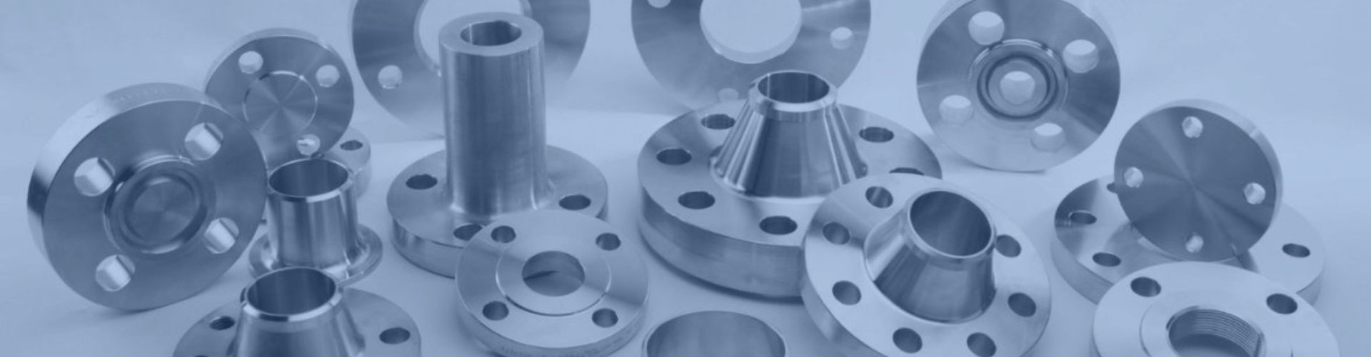
FIP, or Female Iron Pipe, thread is a type of threaded connection used primarily in plumbing and hydraulic systems. It is characterized by its tapered threads designed to create a tight seal when engaged with a corresponding Male Iron Pipe (MIP) thread. The taper of FIP threads helps to ensure a secure fit and seal as the threads are tightened, making it suitable for applications where leak prevention is critical.

History and Development of FIP Thread Standards:

The development of FIP thread standards can be traced back to the early advancements in plumbing and fluid handling industries. Over time, standards such as those set by ANSI/ASME have standardized the dimensions, pitch, and taper angles of FIP threads, ensuring uniformity and compatibility across different manufacturers and applications.

The evolution of FIP thread standards reflects ongoing efforts to improve thread performance and reliability in diverse environments. These standards have been pivotal in enabling the widespread adoption of FIP threads across various industries, providing engineers and technicians with confidence in their application and longevity.

Flare to FIP Brass nipple Fitting Topa

Detailed Analysis of FIP Thread Standards

ANSI/ASME Standards for FIP Threads:

FIP (Female Iron Pipe) threads adhere to standards set by ANSI (American National Standards Institute) and ASME (American Society of Mechanical Engineers). These standards define the dimensions, tolerances, and performance requirements for FIP threads to ensure compatibility and reliability across applications. ANSI/ASME standards provide a framework that manufacturers and engineers rely on to produce and specify FIP threaded components with confidence in their performance and interchangeability.

Dimensions and Specifications of FIP Threads:

FIP threads are characterized by their taper and specific dimensions:

Taper: FIP threads typically have a taper of 1 in 16 on the diameter, meaning the diameter decreases by 1 unit per 16 units of length.

Pitch: The pitch refers to the distance between threads measured along the axis of the thread. Standard pitches for FIP threads are defined by ANSI/ASME to ensure uniformity.

Sizes: FIP threads are available in various sizes, ranging from smaller diameters suitable for residential plumbing to larger sizes used in industrial applications. Common sizes include 1/8″, 1/4″, 3/8″, 1/2″, 3/4″, 1″, and larger.

These specifications are crucial in determining the compatibility of FIP threaded fittings with pipes, valves, and other components in hydraulic and plumbing systems. Proper adherence to these dimensions ensures a secure fit and effective sealing to prevent leaks and maintain system integrity.

Application Areas Where FIP Threads are Commonly Used

FIP threads find widespread application in various industries and environments, including:

Plumbing: FIP threads are commonly used in plumbing systems for connecting fixtures, faucets, and pipe fittings. Their tapered design facilitates a tight seal, preventing water leaks.

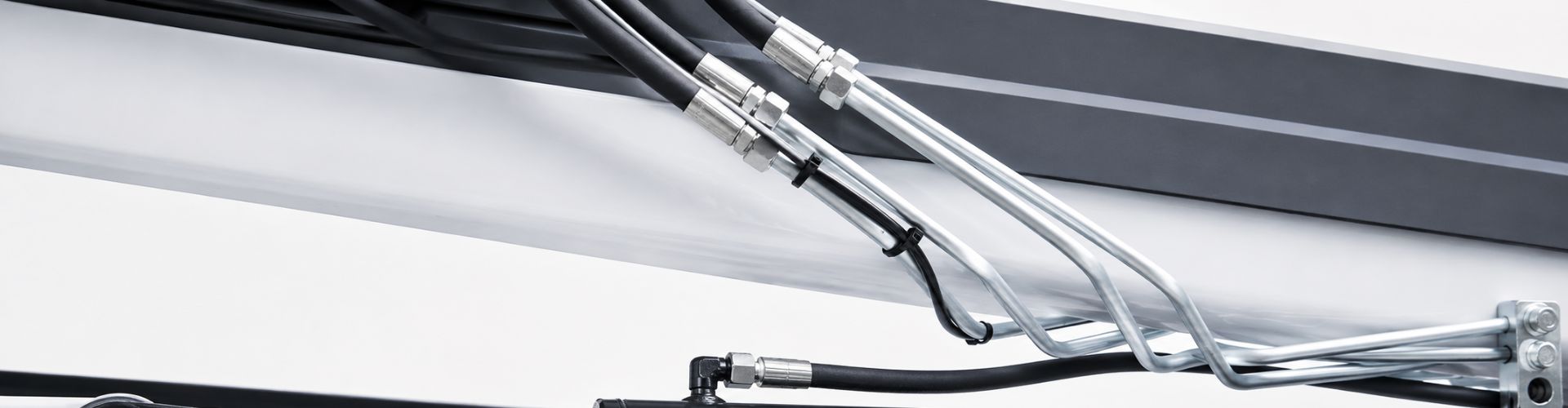
Hydraulics: In hydraulic systems, FIP threads are utilized for connecting pipes, hoses, and fittings. Their reliability and compatibility make them suitable for applications requiring high pressure and fluid containment.

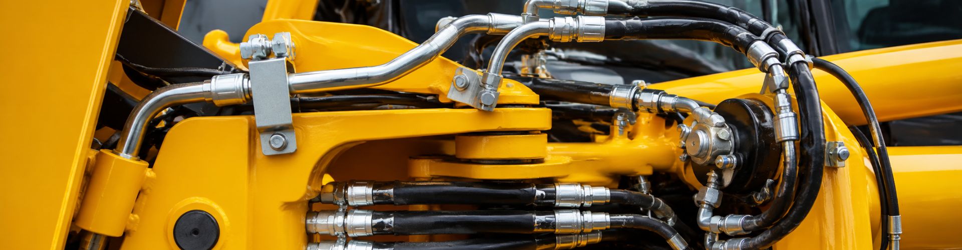
Industrial Equipment: FIP threads are found in industrial machinery and equipment where threaded connections are necessary for fluid transfer, pneumatic systems, and other mechanical operations.

Construction: FIP threads are used in construction for connecting pipes in HVAC (heating, ventilation, and air conditioning) systems, fire suppression systems, and other building infrastructure.

Understanding the application areas of FIP threads helps in selecting the appropriate fittings and components that meet specific operational requirements and environmental conditions. Whether in residential, commercial, or industrial settings, FIP threads play a critical role in ensuring the reliability and functionality of fluid handling systems.

Differences Between FIP and Other Thread Types

Comparison with NPT

Design:

FIP Threads: FIP threads have a taper of 1 in 18, meaning the diameter decreases by 1 unit per 18 units of length.

NPT Threads: NPT threads have a taper of 1 in 16, which is more abrupt compared to FIP threads.

Function:

FIP Threads: Designed primarily for plumbing and hydraulic applications, FIP threads create a tight seal through the taper when engaged with a male thread.

NPT Threads: Widely used in the United States, NPT threads also utilize taper for sealing and are preferred for their interference fit that prevents leaks in plumbing, air compression, and hydraulic systems.

Application Suitability:

FIP Threads: Commonly found in North America and selected global industrial applications, FIP threads excel in environments requiring reliable sealing under pressure, such as in hydraulic fittings and plumbing systems.

NPT Threads: Ideal for applications where a secure, leak-resistant seal is crucial, NPT threads are standardized across various industries in the US and are known for their robust performance in fluid and gas handling systems.

MIP vs FIP

Comparison with BSP

Design:

FIP Threads: Tapered design facilitates a tight seal without additional sealants, suitable for applications where a secure, leak-free connection is paramount.

BSP Threads: Parallel threads require sealants or washers to achieve a seal, offering ease of assembly and disassembly.

Function:

FIP Threads: Specifically engineered for sealing efficiency, FIP threads rely on the taper to enhance sealing effectiveness during assembly.

BSP Threads: Commonly used in Europe, Australia, and Asia, BSP threads provide versatility in fluid and gas handling applications with straightforward installation and maintenance procedures.

Application Suitability:

FIP Threads: Well-suited for environments demanding high sealing integrity, FIP threads are favored in hydraulic systems and industrial settings where reliability is critical.

BSP Threads: Suitable for environments requiring frequent assembly and disassembly, BSP threads accommodate applications in hydraulic fittings, pneumatic systems, and industrial equipment across diverse global markets.

Comparison with MIP Threads

Design and Function:

FIP Threads (Female Iron Pipe):

Design: FIP threads have a tapered internal thread designed to create a tight seal when engaged with a corresponding MIP thread.

Function: FIP threads are typically found on fittings and connectors where they mate with MIP threads, ensuring a secure and leak-resistant connection in plumbing and hydraulic systems.

MIP Threads (Male Iron Pipe):

Design: MIP threads have external tapering designed to fit into FIP threads, creating a tight seal when assembled.

Function: MIP threads are commonly used on pipes, valves, and fittings where they engage with FIP threads, providing a reliable connection that prevents leaks under pressure.

Application Suitability:

FIP Threads:

Suitability: FIP threads are suitable for applications where a secure, leak-free seal is essential, such as in plumbing fixtures, hydraulic fittings, and industrial piping systems.

MIP Threads:

Suitability: MIP threads complement FIP threads by providing a male counterpart that ensures a snug fit and effective sealing, making them integral in various plumbing and hydraulic applications.

Key Differences:

Design: FIP threads have a tapered internal design, while MIP threads have a tapered external design, facilitating a reliable seal when connected.

Function: FIP and MIP threads work together to create a robust, leak-resistant connection crucial in maintaining system integrity in hydraulic and plumbing systems.

Understanding the interplay between FIP and other threads is essential for selecting and assembling fittings and components that ensure efficient fluid handling and minimize the risk of leaks and system failures.

Installation and Maintenance of FIP Threads

Best Practices for Installing FIP Threads

Cleanliness: Ensure that all threads, including those on fittings and pipes, are clean and free of debris or contaminants before installation. Use appropriate cleaning agents and tools to achieve a smooth mating surface.

Thread Sealant: Apply a suitable thread sealant or tape on the male threads before assembling with FIP threads. This helps in achieving a secure and leak-free connection. Avoid over-application of sealant to prevent excess material from entering the hydraulic system.

Proper Alignment: Align the threads carefully to prevent cross-threading, which can damage the threads and compromise the seal. Start threading by hand to ensure threads engage properly before using tools.

Torque Control: Use a torque wrench to tighten FIP threaded connections to the manufacturer’s recommended torque values. Over-tightening can distort threads or damage fittings, while under-tightening may lead to leaks.

Inspection: After installation, visually inspect the connection for any signs of leaks. Perform a pressure test if necessary to verify the integrity of the seal under operating conditions.

Maintenance Tips

Regular Inspections: Periodically inspect FIP threaded connections for signs of wear, corrosion, or damage. Replace fittings or components showing signs of deterioration to prevent leaks and system failures.

Sealant Renewal: Reapply thread sealant or tape as necessary during maintenance intervals or when reinstalling fittings. Ensure compatibility with hydraulic fluids and operating temperatures.

Surface Protection: Protect exposed FIP threads from environmental elements, such as moisture and chemicals, that can accelerate corrosion. Use protective coatings or covers where applicable.

System Flushing: Periodically flush hydraulic systems to remove contaminants that could accumulate around threaded connections and compromise seal integrity.

Documentation: Maintain records of installation dates, torque values, and maintenance activities related to FIP threaded connections. This documentation aids in troubleshooting and ensures compliance with maintenance schedules.

Troubleshooting Common Issues with FIP Threads

Leakage: If leaks occur at FIP threaded connections, check for insufficient thread engagement, damaged threads, or inadequate sealant application. Reassemble with proper alignment and sealant to rectify leaks.

Cross-threading: Misaligned threads can lead to cross-threading, causing damage and leaks. Inspect threads carefully before assembly and correct alignment issues to prevent cross-threading.

Corrosion: Monitor FIP threads for signs of corrosion, especially in corrosive environments. Use corrosion-resistant materials or coatings and perform regular inspections and maintenance to mitigate corrosion effects.

Thread Damage: Examine threads for signs of wear or damage, such as galling or stripping. Replace damaged fittings promptly to avoid compromising system integrity.

Temperature and Pressure Considerations: Ensure that FIP threads are rated for the temperature and pressure conditions within the hydraulic system. Inadequate thread ratings can lead to premature failure under operational stresses.

Adhering to these installation, maintenance, and troubleshooting practices enhances the reliability and longevity of FIP threaded connections in hydraulic systems. Proper care and attention to detail contribute to minimizing downtime, reducing maintenance costs, and optimizing system performance.

Conclusion

Looking ahead, FIP threads are expected to continue playing a pivotal role in hydraulic and plumbing systems globally. Their tapered design and adherence to robust standards make them a preferred choice for applications requiring high sealing integrity and reliability. As industries evolve and demand for efficient fluid handling solutions grows, FIP threads are poised to maintain their relevance and contribute to enhanced system performance and operational efficiency.

FAQ

FIP (Female Iron Pipe) threads are tapered threads on the inside of fittings or connectors. They are designed to create a tight seal when connected with a corresponding Male Iron Pipe (MIP) thread.

FIP threads are commonly found in female fittings such as couplings, elbows, and valves in plumbing, hydraulic systems, and industrial applications.

Yes, FIP threads typically require sealant on the male threads to ensure a proper seal and prevent leaks. This is especially important in pressurized systems.

FIP threads come in various sizes ranging from small diameters used in residential plumbing to larger sizes used in industrial applications. Common sizes include 1/8″, 1/4″, 3/8″, 1/2″, 3/4″, 1″, and larger.

FIP threads can be used interchangeably with compatible male threads, such as MIP (Male Iron Pipe) threads, as long as sizes and thread pitches match. Proper sealant application is crucial for a secure connection.

FIP threads provide a reliable seal due to their tapered design, which increases sealing effectiveness as the threads are tightened. They are suitable for applications requiring leak prevention and secure connections.

Contact Topa

Have a question or suggestion? Fill out the form below to get in touch with one of our experts.

Mixing Brass and Stainless Steel Fittings Is This Possible

Mixing Brass and Stainless Steel Fittings: Is This Possible?

Mixing Brass and Stainless Steel Fittings: Is This Possible?

Table of Contents

Introduction

The compatibility of fittings is pivotal in ensuring the seamless operation and longevity of plumbing and industrial systems. Mixing brass and stainless steel fittings, while potentially advantageous in certain applications, raises important considerations such as galvanic corrosion risks and compatibility with different environmental conditions. This article explores the feasibility, challenges, and best practices associated with combining these two materials to meet diverse industry needs effectively.

Detailed Explanation of Brass Fittings

Brass fittings are primarily composed of copper and zinc alloys, typically ranging in composition from 60% to 90% copper, depending on the specific application requirements. This alloy composition gives brass fittings their characteristic golden-yellow hue and a combination of properties that are highly valued in various industries.

Strengths and Weaknesses

Brass fittings offer several strengths:

Corrosion Resistance: They exhibit excellent corrosion resistance, particularly in freshwater environments.

Malleability: Brass is highly malleable and can be easily shaped into intricate forms, making it suitable for complex fitting designs.

Good Thermal Conductivity: Brass fittings efficiently conduct heat, which is advantageous in applications where thermal management is crucial.

Aesthetic Appeal: The golden color of brass is aesthetically pleasing, making it a preferred choice for visible plumbing fixtures.

However, brass fittings also have some weaknesses:

Susceptibility to dezincification: In certain aggressive water conditions, brass can undergo dezincification, where zinc is leached out, compromising its structural integrity.

Lower Strength Compared to Steel: Brass is softer and has lower tensile strength compared to steel, which limits its use in high-pressure applications.

industrial brass fitting Topa

Common Applications

Brass fittings find extensive use in:

Plumbing: Including residential plumbing, potable water systems, and fittings for taps and valves.

Automotive: Used in hydraulic brake fittings, fuel line fittings, and radiator components.

Electrical and Electronics: Brass fittings are used in electrical connectors and components due to their conductivity and corrosion resistance.

Decorative and Architectural: Brass fittings are popular for decorative hardware, lighting fixtures, and architectural accents.

Detailed Explanation of Stainless Steel Fittings

Stainless steel fittings are alloys of iron combined with chromium and nickel, with varying proportions depending on the specific grade and application requirements. The addition of chromium provides stainless steel with its corrosion-resistant properties, while nickel enhances its strength and durability.

Strengths and Weaknesses

Stainless steel fittings offer several strengths:

Exceptional Corrosion Resistance: Stainless steel is highly resistant to corrosion, making it suitable for harsh environments, including marine and chemical processing industries.

High Strength: Stainless steel fittings exhibit high tensile strength and durability, making them suitable for high-pressure and temperature applications.

Hygienic Properties: Stainless steel is non-porous and easy to clean, making it ideal for food processing, pharmaceutical, and sanitary applications.

Aesthetic Appeal: Stainless steel fittings are available in various finishes and are preferred for their modern and clean aesthetic.

However, stainless steel fittings also have some weaknesses:

Cost: Stainless steel fittings can be more expensive than brass and other materials, impacting initial installation costs.

Hardness: Stainless steel is harder and less malleable than brass, which can make fabrication and machining more challenging.

stainless steel hose fittings factory and supplier china

Common Applications

Stainless steel fittings are widely used in:

Chemical and Petrochemical Industries: For piping and fittings in corrosive environments.

Food and Beverage Processing: Including dairy processing, breweries, and food-grade applications.

Medical and Pharmaceutical: Stainless steel fittings are used in medical equipment, surgical instruments, and pharmaceutical manufacturing.

Construction and Architecture: For structural fittings, railing systems, and architectural elements requiring durability and aesthetic appeal.

Comparison of Physical and Mechanical Properties

When comparing brass and stainless steel fittings based on their material properties and advantages:

Strength and Durability:

Stainless Steel: Stainless steel fittings are renowned for their high tensile strength and durability. They can withstand higher pressures and mechanical stresses compared to brass fittings, making them suitable for applications requiring robust performance and longevity.

Brass: While brass fittings are durable and malleable, they generally have lower tensile strength compared to stainless steel. They are suitable for moderate-pressure applications where their corrosion resistance and ease of machining are advantageous.

Corrosion Resistance:

Stainless Steel: Stainless steel exhibits exceptional corrosion resistance due to its chromium content, which forms a passive oxide layer that protects the metal from oxidation and rusting. This makes stainless steel fittings ideal for environments with high humidity, exposure to corrosive chemicals, or saltwater conditions.

Brass: Brass fittings also offer good corrosion resistance, particularly in freshwater environments and mild atmospheric conditions. However, brass is susceptible to dezincification in aggressive water conditions or environments containing high levels of certain chemicals, which can compromise its structural integrity over time.

Cost and Availability:

Brass: Brass fittings are generally more cost-effective and widely available compared to stainless steel. They are easier to manufacture and require less energy during production, contributing to their lower cost. Brass fittings are readily available in various sizes and configurations, making them a preferred choice for budget-conscious projects.

Stainless Steel: Stainless steel fittings tend to be more expensive than brass due to the higher cost of raw materials (iron, chromium, nickel) and the specialized manufacturing processes involved. They may require sourcing from suppliers specializing in stainless steel products, which can impact availability and procurement lead times.

Understanding these properties and characteristics is essential for selecting the appropriate fittings based on specific application requirements, ensuring optimal performance and longevity in plumbing and industrial systems.

Factors Influencing Compatibility

Several critical factors influence the compatibility of brass and stainless steel fittings when mixed in plumbing and industrial applications:

Galvanic Corrosion Potential

When brass and stainless steel fittings come into contact within a system containing an electrolyte (such as water or moisture), they create a galvanic couple. Stainless steel, being more noble, acts as the cathode, while brass acts as the anode. This electrochemical reaction accelerates the corrosion of the brass, leading to degradation over time. The severity of galvanic corrosion increases with temperature variations and variations in water composition, exacerbating the risk in systems with fluctuating conditions.

Chemical Interactions

The chemical composition of fluids passing through mixed fittings plays a crucial role in their compatibility. Certain chemicals, such as chlorides, sulfates, or acids commonly found in industrial processes or water sources, can react differently with brass and stainless steel. These reactions can alter the protective oxide layers on the surfaces of the fittings, compromising their corrosion resistance and potentially leading to localized corrosion or pitting.

Environmental Conditions

Environmental factors such as temperature fluctuations, humidity levels, and exposure to pollutants significantly impact the compatibility of mixed fittings. High humidity and exposure to aggressive pollutants in the air or water, such as salt or industrial emissions, can accelerate corrosion processes. Coastal environments, where fittings are exposed to saltwater spray, pose particularly high risks due to the corrosive nature of salt.

Potential Risks of Mixing Brass and Stainless Steel Fittings

Mixing brass and stainless steel fittings can introduce several risks that must be carefully managed:

Corrosion and Degradation

Galvanic corrosion between brass and stainless steel fittings can lead to accelerated degradation of the brass components. This corrosion manifests as surface pitting, erosion, or even structural weakening, compromising the integrity of the fittings and the overall system. Over time, corrosion-induced leaks can occur, leading to operational disruptions, maintenance issues, and potential environmental impacts.

Impact on System Longevity

The presence of galvanic corrosion can significantly shorten the operational lifespan of mixed fittings compared to using fittings made from the same material throughout the system. This can necessitate frequent replacements, increasing maintenance costs and downtime. Proper monitoring and proactive maintenance practices are essential to mitigate these risks and extend the longevity of mixed-fitting systems.

Safety Considerations

Corrosion-induced failures in fittings pose safety risks in industrial settings, where leaks or system failures can lead to hazardous conditions, property damage, or environmental contamination. Ensuring the reliability and safety of mixed fittings requires rigorous inspection, adherence to preventive maintenance schedules, and consideration of alternative materials or protective measures where galvanic corrosion risks are high.

Understanding these factors and risks associated with mixing brass and stainless steel fittings is crucial for designing, installing, and maintaining plumbing and industrial systems that prioritize durability, performance, and safety. By implementing appropriate mitigation strategies and monitoring practices, professionals can effectively manage these challenges and optimize the reliability of mixed fitting installations.

Best Practices for Mixing Brass and Stainless Steel Fittings

To minimize compatibility issues when mixing brass and stainless steel fittings in plumbing and industrial applications, several strategies can be implemented:

Use of Dielectric Unions

Dielectric unions are specifically designed to separate dissimilar metals, such as brass and stainless steel, within a plumbing or piping system. They incorporate insulating materials (typically made of plastic or rubber) to prevent direct electrical contact between the two metals. This reduces the risk of galvanic corrosion, prolonging the lifespan of the fittings and the overall system.

Insulating Materials

Applying insulating materials between brass and stainless steel fittings can provide an additional layer of protection against galvanic corrosion. Insulation sleeves or washers made from non-conductive materials create a barrier that minimizes the transfer of electrical currents and electrolytes, thereby reducing the likelihood of corrosion.

Proper Selection Based on Application and Environment

Careful consideration of the specific application requirements and environmental conditions is essential when selecting brass and stainless steel fittings. Factors such as fluid composition, temperature variations, humidity levels, and exposure to corrosive agents should be taken into account.

Choose fittings that are compatible with the expected operating conditions to ensure optimal performance and longevity. For example, in corrosive environments or applications involving high temperatures, selecting stainless steel fittings with appropriate corrosion resistance properties may be more suitable.

Brass with iron fitting

Technical Considerations

When mixing brass and stainless steel fittings in plumbing and industrial applications, it’s crucial to consider several detailed technical aspects to ensure compatibility, performance, and longevity:

Thread Types and Sealing Methods:

Thread Types: Brass and stainless steel fittings may have different thread types based on their material and application. It’s essential to match thread types correctly to ensure a secure and leak-free connection. Common thread types include NPT (National Pipe Thread), BSP (British Standard Pipe), and metric threads.

Sealing Methods: Depending on the application and fluid type, various sealing methods can be used, such as thread sealant tapes (PTFE tape), pipe dope (thread sealant compound), O-rings, or gaskets. Proper sealing prevents leaks and enhances the reliability of the fittings.

Pressure Ratings and Temperature Limits:

Pressure Ratings: Brass and stainless steel fittings have specific pressure ratings that dictate their maximum allowable pressure under operating conditions. It’s essential to verify and match the pressure ratings of mixed fittings to ensure they can withstand the system’s intended pressure without risk of failure.

Temperature Limits: Each material has its temperature limits based on its composition and mechanical properties. Stainless steel typically has higher temperature resistance than brass. Understanding these limits ensures fittings are not exposed to temperatures that could compromise their structural integrity or performance.

Installation Guidelines and Best Practices

Cleanliness: Ensure all mating surfaces of fittings are clean and free from debris, rust, or contamination before installation to promote a proper seal and prevent premature failure.

Proper Torque: Use appropriate torque values during installation to tighten fittings securely without damaging threads or compromising seals. Over-tightening can lead to stress fractures, while under-tightening can result in leaks.

Avoid Mixing Fluids: Avoid mixing incompatible fluids that could accelerate corrosion or degrade the fittings over time. Properly flush and clean the system before installation to remove any contaminants.

Inspect Regularly: Implement a schedule for regular inspection and maintenance of mixed fittings to detect signs of corrosion, leaks, or wear. Prompt replacement of worn or compromised fittings can prevent costly repairs and system downtime.

Conclusion

For professionals and industries considering the mixing of brass and stainless steel fittings, it is recommended to prioritize compatibility testing, thorough system design, and ongoing maintenance protocols. Alternative materials or protective coatings should be considered where galvanic corrosion risks are heightened. By proactively addressing these challenges and leveraging appropriate mitigation strategies, professionals can ensure the reliability, safety, and longevity of mixed-fitting installations, ultimately optimizing system performance and minimizing operational disruptions.

FAQ

While possible, it’s crucial to manage compatibility risks. Using dielectric unions and considering environmental factors can help minimize corrosion.

The main risk is galvanic corrosion, where the less noble metal (typically brass) corrodes when in contact with stainless steel, especially in humid or chemically diverse environments.

Use dielectric unions to separate brass and stainless steel, or employ insulating materials between them. Regular maintenance and monitoring are also essential.

Environments with high humidity, coastal areas with saltwater exposure, or industrial settings with aggressive chemicals pose higher corrosion risks and require careful consideration.

Factor in the fluid type, temperature range, pressure requirements, and environmental conditions. Choose fittings that offer appropriate corrosion resistance and longevity for your specific application needs.

Yes, consider using fittings made from the same material throughout the system or exploring alternative materials like plastic or composite fittings in corrosive environments.

How to Remove Hose from Barbed Fitting

How to Remove Hose from Barbed Fitting

How to Remove Hose from Barbed Fitting

Table of Contents

Introduction

Safely removing hoses from barbed fittings is crucial for maintaining the integrity and functionality of hydraulic systems across various industries. Proper removal techniques not only prevent damage to both the hoses and fittings but also ensure efficient maintenance practices. In this comprehensive guide, we will explore the essential tools needed, step-by-step procedures for different types of barbed fittings, common challenges faced during hose removal, and best practices to uphold safety and longevity.

Understanding Barbed Fittings

Barbed fittings are essential components in hydraulic systems, characterized by their simple yet effective design that securely attaches hoses to pipes or tubing without the need for additional tools like clamps or soldering. Here’s an overview of their definition, anatomy, materials, and applications:

Definition and Basic Anatomy

Barbed fittings feature a tapered, ridged body that resembles a barb or spike, which helps grip and seal the hose when inserted. This design creates a tight seal, preventing leaks and ensuring reliable fluid transfer. The fittings typically consist of:

Barb: The tapered, ribbed end that grips the hose.

Body: The main cylindrical or conical part of the fitting that connects to the pipe or tubing.

Connection End: The threaded or plain end that connects to the system.

Types of Materials Commonly Used

Barbed fittings are manufactured from various materials to suit different application requirements, including:

Brass: Known for its corrosion resistance and durability, making it suitable for general-purpose applications.

Stainless Steel: Offers superior strength and resistance to high temperatures and chemicals, ideal for harsh environments or specialized industries like pharmaceuticals and food processing.

Plastics: Lightweight and cost-effective, commonly used in less demanding applications or where chemical resistance is crucial.

Brass barb hydraulic fitting

Applications in Different Industries

Barbed fittings find extensive use across numerous industries due to their versatility and reliability:

Automotive: Used in fuel lines, brake systems, and cooling systems.

Industrial Manufacturing: Essential for pneumatic and hydraulic systems, fluid transfer, and machinery.

Agriculture: Employed in irrigation systems, pesticide application, and crop spraying equipment.

Medical and Laboratory: Critical for fluid handling in medical devices and laboratory equipment.

HVAC (Heating, Ventilation, and Air Conditioning): Utilized in air and refrigerant lines.

Tools and Equipment Needed

Proper tools are essential for safely removing hoses from barbed fittings to prevent damage and ensure efficient maintenance practices. Using the correct tools not only simplifies the process but also helps maintain the integrity of both the fittings and hoses.

Essential Tools for Hose Removal

Hose Removal Pliers: Specifically designed to grip and pull hoses from barbed fittings without causing damage. These pliers come in various sizes to accommodate different hose diameters and types of fittings.

Utility Knife or Hose Cutter: Useful for cutting hoses cleanly and safely, especially when hoses are tightly fitted or when replacing damaged sections. Ensure the knife or cutter is sharp to avoid fraying the hose ends.

Heat Gun or Hair Dryer (Optional): When dealing with hoses that are stuck or have hardened over time, applying gentle heat can soften the hose material and make it easier to remove from the barbed fitting. Care must be taken to avoid overheating or damaging the hose.

Adjustable Wrench or Spanner: Needed to hold the barbed fitting securely while removing the hose. Choose a wrench that fits snugly to prevent slipping and potential damage to the fitting or surrounding components.

Importance of Using the Correct Tools

Using the appropriate tools is crucial as it:

Prevents Damage: Improper tools or techniques can lead to scratches, tears, or deformation of hoses and fittings, compromising their sealing ability.

Ensures Efficiency: Proper tools make the removal process quicker and more efficient, minimizing downtime and labor costs associated with repairs or maintenance.

Promotes Safety: Safety gear such as gloves and eye protection protects against potential injuries from sharp edges, fluids, or sudden releases of pressure.

Recommendation of Specific Tools for Different Types of Barbed Fittings:

For Straight Barbed Fittings: Hose removal pliers are highly effective due to their ability to grip the hose securely and evenly distribute force along the length of the hose.

For Elbow Barbed Fittings: Use pliers or wrenches that can access tight spaces without compromising grip strength. Adjustable wrenches with angled heads may be beneficial.

For Tightly-Fitted or Older Barbed Fittings: Consider using a heat gun to soften the hose material around the fitting before attempting removal. This technique helps loosen stubborn hoses without damaging the fitting or hose material.

Step-by-Step Guide to Removing Hoses

Before beginning the process of removing hoses from barbed fittings, it’s crucial to prepare the workspace and adhere to safety precautions to ensure a smooth and safe procedure.

Preparing the Workspace and Ensuring Safety Precautions

Turn Off System:

Shut down the system to prevent any unintended fluid release or pressure buildup during hose removal.

Relieve pressure in the hoses by opening valves or vents, ensuring safety from sudden releases.

Wear Protective Gear:

Put on durable safety gloves to protect hands from sharp edges, potential fluid exposure, and abrasions.

Wear safety goggles or a face shield to shield your eyes from debris, fluids, and potential splashes.

Hose Barb Leaking Fix

Removing Hoses from Straight Barbed Fittings

Inspect and Prepare:

Carefully examine the hose and barbed fitting for any visible signs of damage, wear, or corrosion.

Ensure the surrounding area is clear and accessible to maneuver tools effectively.

Use Hose Removal Pliers:

Position hose removal pliers securely around the hose where it connects to the barbed fitting.

Gently squeeze the pliers to grip the hose firmly without excessively squeezing, which could damage the hose.

Twist and Pull:

Apply a slight twisting motion to the pliers while pulling the hose away from the barbed fitting.

This twisting action helps to break the seal formed by the barbs on the fitting, easing the hose removal process.

Repeat if Necessary:

If the hose does not release easily, reposition the pliers and repeat the twisting and pulling motion.

Avoid excessive force to prevent damage to the hose or fitting, ensuring a careful and gradual approach.

Removing Hoses from Elbow Barbed Fittings

Assess Angle and Access:

Evaluate the angle and orientation of the elbow barbed fitting to determine the best approach for removal.

Ensure there is adequate space and clearance around the fitting to maneuver tools effectively.

Use Angled Tools:

Select angled hose removal pliers or an adjustable wrench with a slim profile to securely grip the hose.

Angled tools allow better access to the hose while maintaining a stable grip on the fitting.

Apply Even Pressure:

Apply even pressure on the tool while gently twisting and pulling the hose away from the elbow fitting.

This technique helps to gradually release the hose without damaging the fitting or hose material.

Check for Clearance:

Verify there is sufficient clearance around the elbow fitting to maneuver tools without obstruction.

Adjust positioning as needed to maintain control and prevent accidental damage during the removal process.

Tips for Removing Hoses from Tightly-Fitted or Older Barbed Fittings

Apply Heat (Optional):

If the hose is stubborn or has hardened over time, consider applying gentle heat to the area around the barbed fitting.

Use a heat gun or hair dryer to soften the hose material, facilitating easier removal without causing damage.

Use Cutting Tools:

When dealing with damaged or excessively worn hoses, carefully cut the hose as close to the barbed fitting as possible.

Use a sharp utility knife or hose cutter to ensure a clean cut without compromising the integrity of the fitting.

Inspect Fitting:

After successfully removing the hose, inspect the barbed fitting for any signs of wear, corrosion, or damage.

Clean the fitting thoroughly if necessary before installing a new hose to maintain optimal performance and sealing.

Common Challenges and Solutions

Removing hoses from barbed fittings can present several challenges, especially in industrial settings where equipment may be aged or located in difficult-to-reach areas. Understanding these challenges and having effective troubleshooting strategies can streamline maintenance procedures.

rust barb Fitting

Hose Sticking to Barbed Fitting Due to Age or Material

Challenge:

Age or Material Adhesion: Over time, hoses can adhere tightly to barbed fittings due to factors such as the aging of the hose material or the formation of deposits.

Solution:

Heat Application: Use a heat gun or hair dryer to gently heat the area around the barbed fitting. Heat softens the hose material, making it more pliable and easier to detach from the fitting without causing damage.

Penetrating Lubricants: Apply a small amount of penetrating lubricant around the hose fitting interface. Allow it to sit for a few minutes to loosen the grip before attempting to remove the hose.

Hose Removal Pliers: Utilize hose removal pliers with a strong grip to carefully twist and pull the hose away from the fitting, gradually breaking the seal without damaging the hose or fitting.

Dealing with Barbed Fittings in Hard-to-Reach Areas

Challenge:

Limited Access: Barbed fittings located in tight or confined spaces can restrict the use of standard removal tools and techniques.

Solution:

Angled Tools: Use angled hose removal pliers or wrenches with slim profiles to access fittings in confined spaces more effectively.

Flexible Extensions: Attach flexible extensions to standard tools to reach fittings located behind or underneath machinery or within complex assemblies.

Team Collaboration: Enlist the help of a colleague to assist in holding tools or providing additional illumination while working in challenging areas.

Methods for Removing Damaged Hoses Stuck on Barbed Fittings

Challenge:

Damaged or Worn Hoses: Hoses that are damaged, worn, or have hardened over time can be difficult to remove without risking further damage to the fitting.

Solution:

Cutting Tools: Use a sharp utility knife or hose cutter to carefully cut the hose as close to the barbed fitting as possible. This method allows for the removal of the damaged section of the hose without compromising the integrity of the fitting.

Heat Assistance: Apply gentle heat to the hose around the fitting to soften the material, facilitating easier removal without causing additional damage.

Inspect and Clean: After removing the damaged hose, thoroughly inspect the barbed fitting for signs of wear, corrosion, or debris. Clean the fitting as needed to ensure proper sealing and prevent future issues.

Best Practices for Hose Removal

Implementing best practices for hose removal from barbed fittings not only ensures safety but also maintains the integrity and longevity of hydraulic systems. Here are key practices to follow:

Proper Handling Techniques

Broken hydraulic fitting Topa

Gentle Grip: Use hose removal pliers or appropriate tools with a gentle, yet firm grip on the hose. Avoid excessive squeezing or pulling that could deform or damage the hose material.

Twisting Motion: Apply a slight twisting motion while pulling the hose away from the barbed fitting. This helps break the seal without putting undue stress on the hose or fitting.

Avoid Sharp Tools: Refrain from using sharp or pointed tools that may puncture or cut the hose during removal. Opt for tools specifically designed for hose removal to minimize damage.

Protective Measures: Wear safety gloves to protect hands from potential cuts or abrasions while handling hoses and fittings. Use eye protection to shield against fluid splashes or debris dislodged during the removal process.

Inspecting Fittings After Removal

Visual Examination: Thoroughly inspect the barbed fitting for any signs of wear, corrosion, or damage immediately after removing the hose. Look for cracks, dents, or irregularities that could affect sealing performance.

Cleaning Process: Clean the fitting surface to remove any debris, old sealant, or residue left behind from the previous hose. Use a suitable cleaning agent or solvent as recommended by equipment manufacturer guidelines.

Sealing Condition: Check the condition of the sealing surface on the barbed fitting to ensure it is smooth and free of imperfections. Replace any damaged or worn fittings to maintain optimal sealing integrity.

Replacement Considerations: Assess the overall condition of the fitting and surrounding components. Consider replacing fittings that show signs of extensive wear or damage to prevent future leaks or system failures.

Conclusion

Proper hose removal techniques are crucial for maintaining equipment longevity and efficiency in hydraulic systems. By employing correct tools, gentle handling techniques, and thorough inspections, technicians can minimize downtime, prevent costly repairs, and enhance overall system reliability.

FAQ

Essential tools include hose removal pliers, utility knives or hose cutters, heat guns or hair dryers (optional for stubborn hoses), and adjustable wrenches.

Use gentle gripping techniques with hose removal pliers, apply a twisting motion while pulling the hose, and avoid sharp tools that could puncture or damage the hose.

Try applying gentle heat to soften the hose material or use penetrating lubricants to loosen the grip. If necessary, carefully cut the hose near the fitting using a sharp utility knife or hose cutter.

Inspecting fittings allows you to check for wear, corrosion, or damage that could affect sealing performance. It ensures that fittings are in optimal condition before installing new hoses.

It’s recommended to use hose removal pliers designed specifically for this purpose. They provide a better grip and minimize the risk of damaging the hose or fitting compared to regular pliers.

Always shut down the system and relieve pressure in hoses before starting. Wear safety gloves and eye protection to protect against cuts, abrasions, and exposure to fluids.

How to Install Barbed Hose Fittings

How to Install Barbed Hose Fittings

How to Install Barbed Hose Fittings?

Table of Contents

Introduction

Barbed hose fittings are specialized connectors designed to create a secure, leak-resistant joint between a hose and another component, typically a pipe or another hose. These fittings feature barbs or ridges along their outer surface that grip the inside of the hose when inserted, providing a tight seal.

Definition and Components of Barbed Hose Fittings

Barbed Hose Fittings Components

Barbs: These are the ridges or serrations along the fitting’s surface that grip the hose when inserted, ensuring a tight seal.

Body: The main body of the fitting, which varies in shape and size depending on its specific application and connection requirements.

Threads: Some fittings may include threaded ends to facilitate attachment to other components such as pipes or equipment.

Types of Materials Used

Barbed hose fittings are available in a variety of materials to suit different applications and environmental conditions:

Brass: Commonly used for its durability, corrosion resistance, and suitability for hot water and hydraulic applications.

Stainless Steel: Known for its strength, corrosion resistance, and ability to withstand high temperatures and pressure.

Plastic (e.g., Nylon, Polypropylene): Lightweight options suitable for less demanding applications where chemical resistance and cost-effectiveness are key considerations.

Applications in Different Industries

Barbed hose fittings find extensive use across various industries, including:

Automotive: Used for fuel lines, coolant systems, and vacuum hoses.

Plumbing: Ideal for connecting hoses to fixtures, water pumps, and irrigation systems.

Industrial: Essential for fluid transfer in manufacturing processes, pneumatic systems, and hydraulic machinery.

These fittings provide versatile and reliable connections that cater to specific operational requirements, ensuring efficient fluid handling and minimizing the risk of leaks in critical applications. Understanding the different types and materials of barbed hose fittings is crucial for selecting the right components that best fit your industry’s needs.

Choosing the Right Barbed Hose Fitting

The appropriate barbed hose fitting is crucial for establishing a reliable and efficient fluid handling system. Here are comprehensive factors to consider:

Material Compatibility

Chemical Compatibility: Ensure the fitting material is compatible with the fluids or gases it will encounter. This prevents chemical reactions that could lead to corrosion or material degradation over time.

Temperature and Pressure Ratings: Select fittings rated to withstand your specific application’s operating temperatures and pressures. This ensures safety and prevents performance issues under varying conditions.

Application Specificity

Industry Requirements: Adhere to industry standards and regulations that may specify certain materials or configurations for fittings. Compliance ensures compatibility with industry norms and enhances system reliability.

Environmental Conditions: Evaluate environmental factors such as UV exposure, abrasion, and weather conditions. Choose fittings that are resilient to these elements to maintain longevity and performance.

barb fitting

Size and Measurement Guidelines

Inner Diameter (ID): Accurately measure the inner diameter of the hose to select a fitting with an appropriate barb size. This step is critical for establishing a secure connection that maintains fluid integrity.

Thread Size: Determine the thread size needed for the fitting to properly attach to other components or equipment in your system. Matching thread types and sizes ensures compatibility and prevents potential leaks or fitting misalignment.

By carefully evaluating these factors and guidelines, you can confidently choose barbed hose fittings that meet your specific application requirements. This proactive approach enhances system reliability, minimizes downtime, and optimizes overall operational efficiency in industrial environments. Regular maintenance and periodic inspections further ensure continued performance and longevity of your fluid handling systems.

Common Mistakes to Avoid in Fitting Selection

Incorrect Material Selection: Choosing fittings that are not compatible with the fluid or environment can lead to premature failure or safety hazards.

Improper Sizing: Using fittings with mismatched sizes can cause leaks or fittings that are difficult to install.

Neglecting Pressure Ratings: Fittings rated below the operating pressure may fail under stress, causing leaks or system damage.

Ignoring Environmental Factors: Failing to consider environmental conditions can lead to fittings deteriorating prematurely due to exposure to chemicals, temperature extremes, or UV radiation.

Step-by-Step Installation Process

Ensure a successful installation of barbed hose fittings by following these detailed steps:

Preparation

Before beginning the installation process, it’s crucial to prepare adequately:

Inspecting the Hose and Fitting: Thoroughly examine both the hose and the barbed fitting for any signs of damage, such as cracks, cuts, or deformities. This step ensures that all components are in optimal condition to prevent leaks or failures during operation.

Cutting the Hose to the Correct Length: Measure and cut the hose to the appropriate length using hose cutters or a sharp utility knife. A clean, straight cut is essential to facilitate a proper seal with the barbed fitting, ensuring a secure connection.

Install Hose Barb

Lubrication

Proper lubrication enhances the installation process and ensures a secure connection:

Importance of Lubricating the Hose: Applying a suitable lubricant to the outside of the hose and the barbs of the fitting reduces friction during insertion. This minimizes the risk of damaging the hose material and makes it easier to achieve a tight fit without excessive force.

Types of Lubricants Suitable for Various Materials: Choose lubricants that are compatible with the hose material to avoid degradation or damage. For example, silicone lubricants are suitable for rubber hoses, while soapy water works well with plastic hoses. Avoid using petroleum-based lubricants, as they can deteriorate certain materials over time.

Insertion

Inserting the barbed fitting into the hose requires careful technique to ensure a secure and leak-free connection:

Techniques for Insertion: Gently twist and push the barbed fitting into the hose, employing a twisting motion to help the barbs grip the hose material securely. This technique ensures that the fitting is properly seated without damaging or distorting the hose.

Ensuring a Secure Fit Without Damaging the Hose: Avoid applying excessive force that could potentially damage the hose or stretch the material around the barbs. The fitting should fit snugly without gaps between the hose and the fitting body to maintain integrity.

Securing the Connection

Once the fitting is inserted, secure the connection effectively to prevent leaks:

Using Hose Clamps Effectively: Position hose clamps over the barbed portion of the fitting, ensuring they are evenly spaced and securely fastened around the hose. Select clamps that match the hose diameter to achieve optimal sealing and prevent movement.

Tightening the Clamp to Prevent Leaks: Gradually tighten the hose clamp using a screwdriver or wrench until it is snug against the hose and fitting. Be cautious not to over-tighten, as this may cause damage to the hose or fitting threads.

Testing the Installation

After securing the connection, it’s crucial to verify its integrity and functionality:

Methods for Pressure Testing the Connection: Utilize a pressure testing tool or apply compressed air or water to the system to check for leaks under operational conditions. Monitor the connection closely for any signs of leakage, especially around the barbed fitting and hose clamp areas.

Inspecting for Leaks and Addressing Any Issues: Thoroughly inspect all connections for leaks immediately after testing. If leaks are detected, revisit the installation steps to identify potential causes such as improper insertion, inadequate lubrication, or insufficient tightening of hose clamps. Make necessary adjustments to achieve a tight seal and ensure reliable performance.

By following these step-by-step guidelines, you can ensure the successful installation of barbed hose fittings, maintaining efficiency and reliability in your industrial applications. Regular inspections and proactive maintenance will further enhance system performance and longevity.

Troubleshooting Common Issues

Encountering challenges during the installation of barbed hose fittings is common in industrial applications. Here’s how to troubleshoot and resolve common problems effectively:

Identifying and Fixing Leaks

Inspect the Connection:

Check for Visible Signs of Leakage: Thoroughly examine the area around the fitting and hose clamp for any signs of moisture or drips.

Trace the Leak: Identify the source of the leak, which may result from improper insertion, insufficient tightening of the hose clamp, or compatibility issues between materials.

Reevaluate Installation Steps:

Ensure Proper Insertion: Verify that the barbed fitting is correctly inserted into the hose without causing damage to the hose material or fittings.

Secure Hose Clamp: Ensure the hose clamp is securely tightened around the barbed fitting, creating a tight seal without gaps.

Apply Sealant or Tape:

Use Thread Sealant or Teflon Tape: Apply a suitable thread sealant or Teflon tape to threaded fittings to prevent leaks at connection points.

Seal Around Hose Barb: Apply a small amount of sealant around the hose barb before inserting it into the hose to enhance sealing and prevent leaks.

Replace Damaged Components:

Inspect and Replace: If leaks persist despite adjustments, inspect and replace damaged hoses, fittings, or clamps that may be causing the issue to ensure a secure connection.

Push Lock Fittings with Clamps

Addressing Fittings That Are Difficult to Install

Lubricate Adequately:

Use Suitable Lubricant: Apply a lubricant compatible with the hose and fitting materials to reduce friction during installation and ease fitting insertion.

Ensure Compatibility: Verify that the lubricant chosen does not degrade or damage the materials involved.

Use Proper Tools and Techniques:

Utilize Hose Cutters: Use hose cutters to achieve clean, straight cuts on the hose, facilitating easier installation of fittings.

Techniques for Insertion: Employ twisting and pushing motions when inserting the fitting into the hose to help the barbs grip securely without applying excessive force.

Consider Heat Assistance:

Heat Application: For rigid or stubborn hoses, gently heat the hose with hot water or a heat gun to increase flexibility, making it easier to fit onto the barbed fitting without damaging the materials.

Handling Compatibility Issues Between Hose and Fitting Materials

Verify Material Compatibility:

Check Manufacturer Specifications: Refer to manufacturer guidelines or consult with suppliers to confirm compatibility between the hose and fitting materials to avoid chemical reactions, corrosion, or degradation.

Select Appropriate Fittings:

Material Selection: Choose fittings made from materials that are compatible with the fluid or gas being transferred through the system to ensure long-term reliability and performance.

Consider Environmental Factors: Evaluate environmental conditions such as UV exposure, temperature variations, and chemical exposure that may affect material integrity.

Implement Protective Measures:

Use Specialized Materials: Consider using fittings with alternative materials or coatings that enhance compatibility and durability in challenging environments.

Protective Coatings: Apply protective coatings or treatments to fittings exposed to harsh conditions to prolong their lifespan and maintain performance.

By following these troubleshooting steps and proactive measures, you can effectively resolve installation challenges with barbed hose fittings, ensuring reliable operation and minimizing potential issues in industrial settings. Regular inspection and maintenance will further enhance system integrity and performance over time.

Maintenance and Best Practices

Maintaining barbed hose fittings is essential for prolonging their lifespan and ensuring reliable performance in industrial applications. Here are key tips and best practices:

Tips for Maintaining Barbed Hose Fittings

Broken hydraulic fitting Topa

Regular Inspection:

Conduct routine inspections of fittings, hoses, and clamps for signs of wear, corrosion, or leaks.

Inspect fittings after installation and periodically during operation to detect potential issues early.

Replacement Schedules:

Establish a maintenance schedule for replacing fittings and hoses based on manufacturer recommendations or observed wear.

Replace components promptly if they show signs of damage or deterioration to prevent failures and leaks.

Cleaning and Lubrication:

Clean fittings and hoses regularly to remove debris, dirt, or contaminants that can affect sealing and performance.

Apply appropriate lubrication during installation and maintenance to facilitate easier fitting insertion and prevent friction-related damage.

Tightening and Adjustment:

Ensure hose clamps are securely tightened to maintain a tight seal around barbed fittings.

Periodically check and adjust clamp tightness to compensate for any loosening due to vibration or temperature changes.

Best Practices for Ensuring Longevity and Performance

Use Compatible Materials: Select fittings and hoses that are compatible with the fluids, gases, and environmental conditions they will encounter.

Follow Installation Guidelines: Adhere to manufacturer installation instructions and industry best practices to ensure proper fitting assembly and sealing.

Monitor Operating Conditions: Regularly monitor operating temperatures, pressures, and environmental factors to anticipate potential issues and take preventive action.

Conclusion

In summary, selecting and installing barbed hose fittings requires attention to detail and adherence to best practices to ensure optimal performance and longevity. By employing safe installation techniques and proactive maintenance, you can maximize the efficiency and longevity of barbed hose fittings to ensure the continued success of your industrial operations.

FAQ

BSP hydraulic hose fittings are standardized fittings used to connect hydraulic hoses and pipes. They ensure a secure and leak-free connection in hydraulic systems.

Topa provides a wide range of BSP hydraulic hose fittings in various sizes to accommodate different hydraulic system requirements. 

Yes, Topa’s BSP hydraulic hose fittings are designed to meet international standards and are compatible with fittings from other reputable brands. This ensures versatility and ease of integration into existing hydraulic setups.

Our BSP hydraulic hose fittings are manufactured using high-quality materials such as [specify materials, e.g., stainless steel, brass] to ensure durability, corrosion resistance, and long-term performance in demanding environments.

Yes, Topa understands the importance of meeting specific customer requirements. We offer customization options for BSP hydraulic hose fittings, including special sizes, configurations, and finishes to suit unique applications.

Ordering from Topa is straightforward. Simply [describe the ordering process, e.g., visit our website, contact our sales team], provide details about the BSP hydraulic hose fittings you need, and our team will assist you with pricing, availability, and delivery options.


Explore Hydraulic Flange Types

Explore Hydraulic Flange Types: A Comprehensive Overview

Explore Hydraulic Flange Types: A Comprehensive Overview

Introduction

Hydraulic flange fittings allow for a secure and leak-free connection, which is essential for efficient fluid transfer. These fittings are key components in hydraulic systems that ensure seamless operation and reliability under varying pressures and environmental conditions. By securely connecting pipes, tubes, or hoses, hydraulic flange couplings prevent fluid leakage, thereby maintaining system integrity and optimizing performance. Their importance lies not only in functional reliability but also in their ability to improve operational safety and reduce maintenance costs.

What are Hydraulic Flange Fittings?

Hydraulic flange fittings are essential components characterized by a flat surface featuring grooves and an O-ring on one end. This design is meticulously crafted to establish a robust seal, crucial for containing fluids under high pressures within hydraulic systems. The opposite end of these fittings is adaptable, typically connecting to either a hose or threaded component, thereby enabling versatile applications across diverse industrial environments.

One pivotal aspect of hydraulic flange fittings is their integration with flange clamps. These clamps play a pivotal role in ensuring the fittings’ secure attachment to pipes or machinery, thereby enhancing system reliability. By facilitating easy assembly and disassembly, hydraulic flange fittings with flange clamps allow for efficient maintenance procedures, minimizing downtime and operational disruptions.

Types of Hydraulic Flange Fittings

Hydraulic systems rely on various types of flange fittings to ensure secure connections and efficient fluid transfer across different applications and industries. Here’s an overview of the key types:

Hydraulic Hose Flange Fitting

Hydraulic hose flange fittings are specialized components essential for securely connecting hoses to hydraulic systems, ensuring reliable fluid transfer and containment. These fittings are available in various pressure ratings tailored to different operational needs:

SAE Code 61/3000 psi: This type of hydraulic hose flange fitting is well-suited for medium-pressure hydraulic applications. It provides a secure connection that can withstand pressures up to 3000 pounds per square inch (psi), making it suitable for a wide range of industrial and mobile hydraulic equipment.

SAE Code 62/6000 psi: Designed for higher-pressure hydraulic systems, SAE Code 62 fittings offer robust performance under increased pressure levels. With a pressure rating of 6000 psi, these fittings are commonly used in demanding hydraulic applications where durability and reliability are crucial, such as heavy machinery and construction equipment.

High-pressure/9000 psi: For extreme high-pressure environments, hydraulic hose flange fittings rated at 9000 psi provide exceptional strength and sealing capabilities. These fittings are specifically engineered to handle intense hydraulic pressures found in specialized industrial applications, including mining operations, offshore drilling rigs, and high-performance hydraulic systems.

Each type of hydraulic hose flange fitting is meticulously designed to ensure compatibility with specific pressure requirements and operational conditions. By selecting the appropriate fitting based on pressure ratings and application needs, industries can achieve optimal performance, reliability, and safety in their hydraulic systems.

Hydraulic flange fittings China Manufacturer Topa in China

Thread Flange Fitting

Thread flange fittings are versatile components designed with threads on both the inside and outside, facilitating the connection of pipes or valves in hydraulic and fluid handling systems. This dual-threaded design offers significant advantages in terms of assembly, disassembly, and maintenance:

Versatile Connectivity: Thread flange fittings provide a flexible solution for joining pipes or valves without requiring welding. The threaded design allows for easy installation and removal, making them ideal for applications where frequent assembly and disassembly are necessary.

Sealing Capabilities: Properly tightened threaded flange fittings create a secure seal, preventing leaks and ensuring reliable fluid containment. This sealing capability is crucial for maintaining system integrity and operational safety in hydraulic applications.

Slip-On Flanges

Slip-on flanges are characterized by their simple yet effective design, which facilitates easy installation and alignment in various industrial applications. Here’s a detailed overview of their external features and typical uses:

External Appearance: Slip-on flanges feature a flat, circular shape with a raised face on the sealing surface. This raised face helps in creating a tight seal when the flange is welded to the pipe, ensuring leak-free operation. They also have a smooth inner bore that matches the pipe diameter, allowing for seamless flow of fluids through the system.

Usage and Applications: Slip-on flanges are commonly used in scenarios where ease of installation and cost efficiency are priorities. They are particularly favored in less critical applications or systems with moderate pressure requirements. Industries such as water treatment plants, low-pressure hydraulic systems, and plumbing installations often utilize slip-on flanges due to their straightforward installation process and lower initial cost compared to other flange types.

Limitations in High-Pressure Environments: While slip-on flanges offer advantages in terms of ease of installation, they may have limitations in high-pressure environments. The welding connection, while robust, may not provide the same level of strength and pressure resistance as weld neck or socket weld flanges. Therefore, slip-on flanges are typically recommended for applications where moderate pressures are anticipated and where the operational demands do not require the highest level of structural integrity.

SAE Socket Weld Flange flat factory

Socket Weld Flanges

Socket weld flanges have a socket-like end with an internal bore that matches the outer diameter of the pipe. This design allows the pipe to be inserted into the socket, creating a precise fit. The flange also features a flat, circular face with bolt holes for securing it to another flange or component using bolts and nuts. The sealing surface may be raised to accommodate a gasket for optimal sealing.

Usage and Applications: Socket weld flanges are primarily used in systems where moderate pressures and smaller pipe sizes are involved. They are particularly suitable for piping systems handling fluids such as water, steam, oil, and gas in industries such as petrochemical, chemical processing, and food processing. Their robust construction and secure weld connection make them ideal for applications requiring reliable sealing and fluid containment.

Connection Method: The installation of socket weld flanges involves inserting the pipe into the socket end and then performing fillet welding around the joint. This welding method creates a strong and permanent connection that enhances structural integrity and minimizes the risk of leaks. Socket weld flanges are preferred for their simplicity in installation and maintenance, allowing for easy inspection and disassembly when necessary.

Flow Dynamics: Due to their smooth internal bore and precise fit with the pipe, socket weld flanges promote excellent flow dynamics within the system. This feature reduces turbulence and pressure drop, contributing to efficient fluid transfer and operational efficiency.

Blind Flanges

Blind flanges are flat, solid plates with no openings or bores. They feature a raised face on the sealing surface, which accommodates a gasket for creating a tight seal when bolted to another flange or component. The bolt holes around the perimeter allow for secure attachment using bolts and nuts.

Functionality: The primary function of blind flanges is to block off or seal the end of a pipeline, valve, or pressure vessel opening. By preventing the flow of fluids or gases, blind flanges ensure system integrity and safety during maintenance, inspection, or when future expansion is anticipated. They are commonly used to isolate sections of pipelines or equipment that require temporary or permanent closure.

Applications: Blind flanges find widespread application in various industries, including oil and gas, chemical processing, pharmaceuticals, and water treatment plants. They are essential in hydraulic systems where fluid control, system isolation, or pressure containment is critical. Blind flanges are particularly useful during system shutdowns, maintenance procedures, or when performing hydrostatic testing to verify the integrity of pipelines or vessels.

Types and Variations: Blind flanges are available in different types to accommodate specific operational requirements. They may include standard blind flanges with raised faces for standard sealing applications or special blind flanges designed for high-pressure or corrosive environments. The selection of materials such as carbon steel, stainless steel, or alloy steel ensures compatibility with varying fluid types and system conditions.

Installation and Maintenance: Installing blind flanges involves aligning the flange with the pipe or equipment opening and bolting it securely in place. The use of a suitable gasket between the flange faces ensures a leak-proof seal. Maintenance of blind flanges typically involves periodic inspection, gasket replacement, and ensuring proper bolt torque to maintain sealing integrity.

Lap Joint Flanges

Lap joint flanges are unique components designed to facilitate easy assembly, alignment, and maintenance in hydraulic and industrial piping systems. Here’s a detailed exploration of their features and practical applications:

Component Design: Lap joint flanges consist of two main components:

Stub End: A short piece of pipe with a welded or flanged connection to the pipeline.

Backing Flange: A circular disc with bolt holes that slides over the pipe end and overlaps the stub end.

Assembly and Installation: The installation of lap joint flanges involves:

Welding the stub end to the pipe.

Sliding the backing flange over the pipe end until it rests against the stub end.

Securing the flange to the stub end using bolts and nuts through the bolt holes in the backing flange.

Sealing and Compatibility: Lap joint flanges utilize a gasket placed between the stub end and the backing flange to achieve a secure seal. This sealing method allows for easy replacement of the gasket when necessary, enhancing maintenance efficiency. Lap joint flanges are available in various materials and pressure ratings to suit different operational requirements, ensuring compatibility with diverse piping configurations and fluid handling applications.

Applications: Lap joint flanges find widespread use in industries where versatility, ease of maintenance, and system adaptability are essential. They are commonly employed in chemical processing, petrochemical, food and beverage, and power generation industries. Their ability to facilitate quick assembly and disassembly makes them ideal for systems that undergo frequent upgrades, modifications, or inspection procedures.

Selection Considerations for Hydraulic Flange Fittings

Choosing the appropriate hydraulic flange fittings involves careful consideration of several key factors to ensure optimal performance, longevity, and safety in hydraulic operations. Here’s an expanded look at the critical selection considerations:

Material Compatibility

Hydraulic systems operate with a variety of fluids, each having specific chemical properties that can affect the materials used in flange fittings. It’s essential to select materials such as stainless steel, carbon steel, or alloy steel that offer compatibility with the fluid being conveyed. This prevents corrosion, degradation, or contamination of the fluid and ensures the durability of the fittings over time.

Pressure Ratings

Hydraulic flange fittings are rated to withstand different pressure levels, ranging from low to ultra-high pressures. It’s crucial to match the pressure rating of the fittings with the operating pressures of the hydraulic system. Using fittings with insufficient pressure ratings can lead to leaks, system failures, or safety hazards. Conversely, over-specifying pressure ratings may result in unnecessary costs. Careful assessment of the system’s pressure requirements ensures reliable performance under operational conditions.

Temperature Variations

Hydraulic systems may operate across a wide range of temperatures, from extreme cold to high heat environments. Flange fittings should be selected based on their ability to withstand these temperature variations without compromising performance or structural integrity. Temperature considerations also affect the choice of sealing materials, ensuring effective sealing and preventing leakage under fluctuating thermal conditions.

Environmental Conditions

The operating environment plays a significant role in the selection of hydraulic flange fittings. Factors such as exposure to moisture, chemicals, abrasive materials, UV radiation, and atmospheric conditions must be evaluated. Choosing fittings with appropriate corrosion resistance, weatherproofing, and durability ensures longevity and reliability in harsh environments. Environmental factors also influence maintenance intervals and lifecycle costs associated with hydraulic systems.

System Compatibility and Integration

Hydraulic flange fittings should integrate seamlessly with existing system components, including pipes, valves, pumps, and other fittings. Compatibility considerations include dimensional compatibility (size and type), connection methods (welding, threading, socket welding), and alignment requirements. Proper integration enhances system efficiency, minimizes installation complexities, and supports operational reliability.

Quality and Standards Compliance

Selecting hydraulic flange fittings that comply with industry standards and quality certifications (such as ASTM, ASME, and ISO) ensures conformity to safety, performance, and reliability benchmarks. Certification indicates that fittings have undergone rigorous testing and meet specified criteria for material strength, dimensional accuracy, and manufacturing consistency. Adhering to recognized standards enhances confidence in the fittings’ performance and longevity.

Conclusion

Hydraulic flange fittings stand as essential components that play a pivotal role in maintaining the integrity, efficiency, and safety of hydraulic systems across various industrial applications. Through a comprehensive understanding of their types, applications, and critical selection criteria, professionals can make informed decisions to enhance system performance and reliability.

FAQ

Hydraulic flange fittings are essential components used to connect pipes, hoses, or valves in hydraulic systems. They ensure secure connections that withstand high pressures, facilitating efficient fluid transfer in various industrial applications.

Common types include weld neck, slip-on, socket weld, blind, and lap joint flanges. Each type has specific features and advantages suited to different operational needs, from high-pressure environments to systems requiring frequent maintenance.

Consider factors such as material compatibility, pressure ratings, temperature variations, and environmental conditions. Choosing fittings that match these criteria ensures optimal performance, longevity, and safety in hydraulic operations.

They are typically made from materials like stainless steel, carbon steel, or alloy steel, selected based on their compatibility with the fluid being conveyed and environmental conditions. These materials offer corrosion resistance and durability.

Hydraulic flange fittings play a critical role in maintaining system integrity, minimizing leaks, and supporting efficient fluid handling. They are essential for ensuring operational reliability, safety, and compliance with industry standards.

For detailed specifications, technical guidance and expert advice, we recommend that you contact Topa, our specialized technicians are always ready to respond to you!

Contact Topa

Save 30% on maintenance costs with our easy-install hydraulic fittings. Contact Now!