
How to Install PTFE Fittings
How to Install PTFE Fittings Contact Us Introduction Proper installation
How to Install PTFE Fittings Contact Us Introduction Proper installation

SAE ORB vs JIC Fitting: Key Differences You Should Know

PTFE Fittings vs AN Fittings: What You Need to Know

Hydraulic Quick Coupler Won’t Lock? Contact Us Introduction When a

NPT vs AN Fittings: Which Is Right for Hydraulic System?

How to Relieve Pressure on Hydraulic Coupler Contact Us Table

AN Fitting Measurements: Comprehensive Chart Contact Us Table of Contents

Quick Coupling Technologies: Everything You Need to Know Contact Us

How to Install Braided Hose Fittings Contact Us Introduction Installing
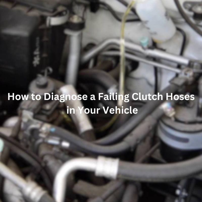
How to Diagnose a Failing Clutch Hoses in Your Vehicle