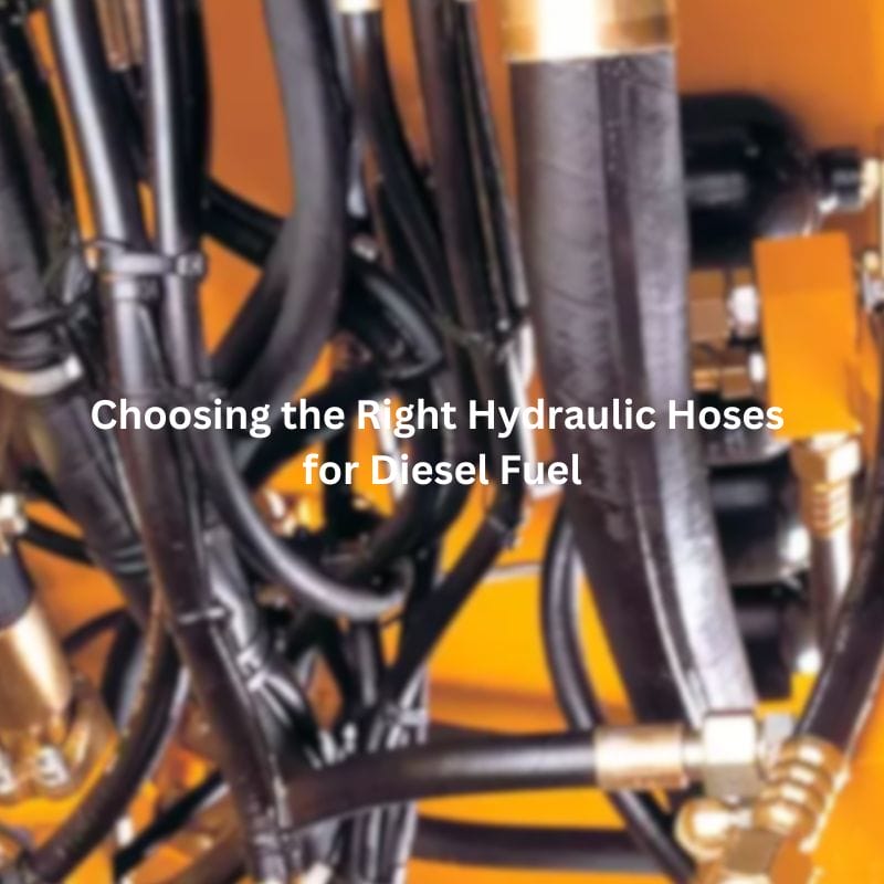
Choosing the Right Hydraulic Hoses for Diesel Fuel
Choosing the Right Hydraulic Hoses for Diesel Fuel Introduction Selecting
Choosing the Right Hydraulic Hoses for Diesel Fuel Introduction Selecting

Five Advantages of Quick Connect Fittings Contact Us Table of
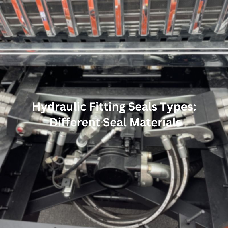
Hydraulic Fitting Seal Types: Different Seal Materials Contact Us Table
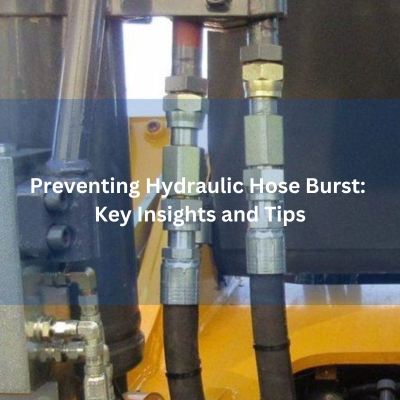
Preventing Hydraulic Hose Burst: Key Insights and Tips Contact Us

How to Fix a Leaking Brass Fitting? Table of Contents
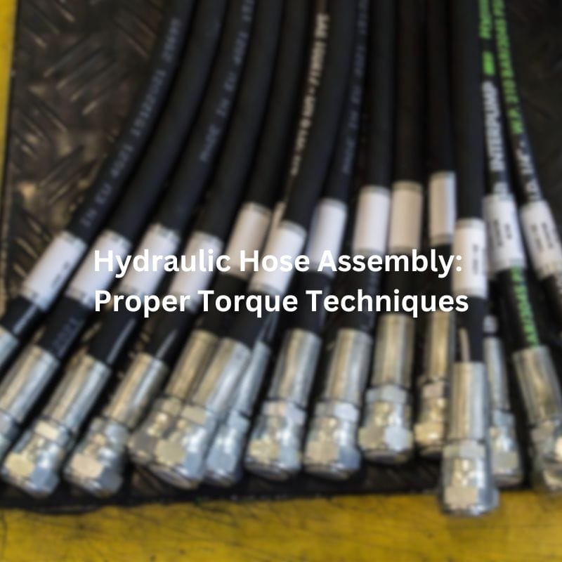
Hydraulic Hose Assembly: Proper Torque Techniques Contact Us Introduction When

Choosing the Right Metric Hydraulic Fitting Standard Contact Us Table

When Should You Use Permanent Hose Fittings? Contact Us Table

SAE J1926 Ports: Key System Design Considerations Contact Us Table

Properly Sized Hydraulic Tubing: Prevents Pressure Drops Contact Us Table